EP4209123B1 - Dreschkorb für einen mähdrescher - Google Patents
Dreschkorb für einen mähdrescher Download PDFInfo
- Publication number
- EP4209123B1 EP4209123B1 EP22200164.6A EP22200164A EP4209123B1 EP 4209123 B1 EP4209123 B1 EP 4209123B1 EP 22200164 A EP22200164 A EP 22200164A EP 4209123 B1 EP4209123 B1 EP 4209123B1
- Authority
- EP
- European Patent Office
- Prior art keywords
- threshing
- processing device
- crop processing
- adjustable elements
- concave
- Prior art date
- Legal status (The legal status is an assumption and is not a legal conclusion. Google has not performed a legal analysis and makes no representation as to the accuracy of the status listed.)
- Active
Links
Images


Classifications
-
- A—HUMAN NECESSITIES
- A01—AGRICULTURE; FORESTRY; ANIMAL HUSBANDRY; HUNTING; TRAPPING; FISHING
- A01D—HARVESTING; MOWING
- A01D41/00—Combines, i.e. harvesters or mowers combined with threshing devices
- A01D41/12—Details of combines
-
- A—HUMAN NECESSITIES
- A01—AGRICULTURE; FORESTRY; ANIMAL HUSBANDRY; HUNTING; TRAPPING; FISHING
- A01F—PROCESSING OF HARVESTED PRODUCE; HAY OR STRAW PRESSES; DEVICES FOR STORING AGRICULTURAL OR HORTICULTURAL PRODUCE
- A01F12/00—Parts or details of threshing apparatus
- A01F12/18—Threshing devices
- A01F12/28—Devices for adjusting the concaves
-
- A—HUMAN NECESSITIES
- A01—AGRICULTURE; FORESTRY; ANIMAL HUSBANDRY; HUNTING; TRAPPING; FISHING
- A01F—PROCESSING OF HARVESTED PRODUCE; HAY OR STRAW PRESSES; DEVICES FOR STORING AGRICULTURAL OR HORTICULTURAL PRODUCE
- A01F12/00—Parts or details of threshing apparatus
- A01F12/18—Threshing devices
- A01F12/24—One-part threshing concaves
-
- A—HUMAN NECESSITIES
- A01—AGRICULTURE; FORESTRY; ANIMAL HUSBANDRY; HUNTING; TRAPPING; FISHING
- A01F—PROCESSING OF HARVESTED PRODUCE; HAY OR STRAW PRESSES; DEVICES FOR STORING AGRICULTURAL OR HORTICULTURAL PRODUCE
- A01F12/00—Parts or details of threshing apparatus
- A01F12/18—Threshing devices
- A01F12/26—Multi-part threshing concaves
Definitions
- the invention relates to a threshing concave for a combine harvester according to the preamble of claim 1.
- Agricultural combine harvesters are large machines that harvest, thresh, separate and clean agricultural crops that contain grain.
- the clean grain obtained is stored in a grain tank on the combine harvester.
- Threshing is usually carried out using tangential threshing devices with a threshing concave and a threshing drum that conveys the crop tangentially, or axial threshing devices with axial threshing rotors that convey the crop axially and also work together with a threshing concave.
- the threshing concaves consist of curved and cross bars that leave gaps between them.
- the threshing concave surrounds the threshing drum over part of its circumference and encloses a gap with it through which the crop to be threshed is forced. As the crop is conveyed through the gap, parts of the crop (the grain) separate, fall through the gaps and are fed to a cleaning device. Depending on the nature of the crop, certain components can be removed more or less easily, so it makes sense to be able to adapt the threshing concaves to the respective crop.
- a crop processing device at the inlet of the threshing concave as an additional threshing means, which is movable between an active and inactive position, usually rotatable, in order to thresh the crop at the inlet of the threshing concave more or less aggressively.
- additional threshing means which is movable between an active and inactive position, usually rotatable, in order to thresh the crop at the inlet of the threshing concave more or less aggressively.
- a power-operated actuator that can be controlled from the combine harvester's cab by an operator or by an automatic system.
- the adjustment of the crop processing device at the inlet of the threshing drum is usually carried out manually or by an actuator.
- threshing concaves which have both a deactivatable crop processing device arranged at the inlet and adjustable elements (arranged downstream of the inlet of the threshing concave) require two actuating elements in the form of manually operable levers or similar or, in the case of automatic or remote actuation, in the form of actuators, which entails a relatively high level of effort.
- the US 2019/0254233 A1 shows an axial combine harvester with a rotor and a threshing concave that is adjustable relative to the rotor and can be moved into an inactive position by means of an actuator.
- the object underlying the invention is to provide a threshing concave of the type mentioned at the beginning for a combine harvester in which the problems mentioned do not exist or exist to a reduced extent.
- a threshing concave for a combine harvester is provided with a crop processing device arranged on the threshing concave, which is adjustable between an active and an inactive position, elements arranged downstream of the inlet of the threshing concave, which are adjustable between an active and an inactive position, and an adjustment mechanism for separately adjusting the crop processing device and the adjustable elements, which comprises a movable adjustment element which is coupled to the crop processing device and the adjustable elements.
- the adjusting element is coupled to the crop processing device and the adjustable elements such that in a first position of the adjusting element the crop processing device and the adjustable elements are in the active position, in a second position of the adjusting element the adjustable elements are in the inactive position and the crop processing device are in the active position (or vice versa) and in a third position of the adjusting element the crop processing device and the adjustable elements are in the inactive position.
- both the crop processing device and the adjustable elements can be moved separately between an active and an inactive position. Therefore, only a single actuating element is required.
- the crop processing device and/or the adjustable element can not only be moved between an active and inactive position by the movable element of the adjustment mechanism, but in one possible embodiment can also be moved into one or more or any number of intermediate positions between the active and inactive positions.
- the degree of action of the adjustable element and/or the crop processing device can thus be varied in more than one stage or continuously, each independently of one another.
- any third, fourth, etc. adjustable device of the threshing concave could also be moved by the movable element of the adjustment mechanism.
- the crop processing device can be a rotatable body attached to the inlet of the threshing concave with threshing elements in the form of projections attached to it.
- the adjustable elements can be deawning plates or finger strips.
- the adjusting element can be a rotatable disc provided with two cams, each of which is coupled to the crop processing device and the adjustable elements via cams and coupling elements.
- the concave can be equipped with a tangentially conveying threshing drum or an axially conveying axial threshing rotor.
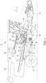
- the Figure 1 shows a self-propelled combine harvester 10 with a frame 12 which is supported on the ground by front, driven and rear steerable wheels 14 and is moved by these.
- the wheels 14 are set in rotation by means of drive means (not shown) in order to move the combine harvester 10, for example, over a field to be harvested.
- a harvesting device 18 in the form of a cutting unit is detachably connected to the front end of the combine harvester 10 in order to harvest harvesting material in the form of grain or other threshable crops from the field during harvesting and to feed it upwards and backwards through an inclined conveyor 20 to a multi-drum threshing unit which - arranged one behind the other in the direction of travel V - comprises a threshing drum 22, a stripping drum 24, an overshot conveyor drum 26, a separating drum 28 and a discharge conveyor 30. Downstream of the discharge conveyor 30 there is a straw shaker 32.
- the threshing drum 22 is surrounded in its lower and rear area by a threshing concave 34.
- a cover 35 provided with openings or closed, while above the conveyor drum 26 there is a fixed Cover and a separating basket 36 with adjustable finger elements is located below the separating drum 28.
- a separating grate 38 is arranged below the undershot discharge conveyor 30.
- a front conveyor floor 40 is located below the multi-drum threshing unit.
- a rear conveyor floor 42 is arranged below the straw walker 32.
- the conveyor floors 40, 42 transport the mixture of grain, short straw and chaff from the threshing concave 34, the separating concave 46 and the separating grate 38 as well as from the straw walker 32 to a cleaning device 46.
- Grain cleaned by the cleaning device 46 is fed by means of a grain auger 48 to an elevator (not shown), which transports it into a grain tank 50.
- a return auger 52 returns unthreshed parts of the ears of grain back to the threshing process through another elevator (not shown).
- the chaff can be ejected at the rear of the screening device by a rotating chaff distributor, or it is discharged by a straw chopper (not shown) arranged downstream of the straw walker 32.
- the cleaned grain from the grain tank 50 can be unloaded through a unloading system with cross augers 54 and a unloading conveyor 56.
- the systems mentioned are driven by an internal combustion engine 58 and controlled and operated by an operator from a driver's cab 60.
- the various devices for threshing, conveying, cleaning and separating are located inside the frame 12. Outside the frame 12 there is an outer shell, most of which can be opened.
- the threshing mechanism could also only comprise the threshing drum 22, the stripping drum 24 and the discharge conveyor 30, i.e. be designed as a conventional tangential threshing mechanism without a separating drum 28 and without a conveyor drum 26, in which the discharge conveyor 30 directly follows the threshing drum 22.
- all direction information such as front, rear, above and below, refer to the forward direction of travel V of the combine harvester 10.
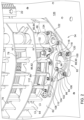
- the threshing concave 34 itself is of conventional construction and comprises two curved side walls 62 adapted to the radius of the threshing drum 22, between which threshing bars 68 extend (in the front area of the threshing concave 34).
- the threshing concave 34 comprises further curved bars 64, between which circumferentially extending basket wires 76 are arranged.
- Further basket wires 78 are also arranged between the threshing bars 68 These are thinner than the basket wires 76 arranged in the rear area of the concave 34 between the arched strips 64, but are present in greater numbers.
- a crop processing device 84 is arranged upstream of the threshing concave 34 with respect to the flow direction of the crop.
- the crop processing device 84 comprises a body 66 which extends between the side walls 62 and is mounted there so as to be rotatable about its longitudinal axis.
- Threshing elements 80 are attached to the body 66 and can be moved between an active position (see Figures 2 , 3 and 4 ), in which they are in contact with the crop and provide a certain threshing effect, and an inactive position ( Figure 5 ) in which they are spaced from the crop.
- the crop processing device 84 can be moved accordingly EP 2 036 425 A1 or DE 10 2014 224 780 A1 the disclosure of which is incorporated by reference into these documents.
- adjustable elements 86 are provided, which in the embodiment shown are designed as so-called deawning plates 82.
- the adjustable elements 86 are (as shown in the Figures 3 to 5 recognizable) between an open position (in Figure 2 , 4 and 5 shown) and a closed position (in Figure 3 shown).
- the deawner plates 82 serve to prevent crop components (particularly grain) from passing through between the threshing bars 68 in the closed position, so that the crop is processed more intensively in the front area of the concave than when the deawner plates 82 are open and can only pass downwards between the concave wires 74 in the rear area of the concave 34 at the earliest.
- the deawner plates 82 are known per se (cf. DE 1 989 612 U ), and in another embodiment could be replaced by adjustable finger strips (cf. the prior art mentioned above) as adjustable elements.
- the threshing concave 34 therefore comprises an adjustable crop processing device 84 and the adjustable elements 86, which can be adjusted separately from one another between an active and an inactive position.
- the crop processing device 84 and the adjustable elements 86 are provided with separate actuating means in the form of manually operated levers or actuators for adjusting
- the present invention relates to an adjustment mechanism 92 which allows both the crop processing device 84 and the adjustable elements 86 to be moved between an active and inactive position with a single adjustment element 88, separately from one another.
- the adjusting element 88 designed as a cam disk 90, is connected in a rotationally fixed manner to a shaft 96 which extends orthogonally to the plane of the side cheek 62 and is mounted centrally on the cam disk 90 and which is rotatably mounted on a downwardly extended section 94 of one of the side cheeks 62.
- the shaft 96 and thus the adjusting element 98 are in turn moved by the said actuating means about their longitudinal and rotational axes between two end positions, one of which is in Figure 3 and one in Figure 5 shown, rotatable, while the Figure 4 shows an intermediate position.
- the cam disk 90 comprises two curved tracks 98, 100 designed as curved slots.
- a first control cam 102 engaging in and cooperating with the first cam track 98 is attached to a first lever 104 which is supported by a first bearing 106 at the lower region of the section 94.
- the angled first lever 104 is rotatably connected at its second end to a first push rod 108, which in turn is rotatably coupled at its rear end to a first bracket 110 extending forwards.
- the front ends of the adjustable elements 86 (deawning plates 82) are rotatably articulated to the first bracket 110, which are supported with their rear ends on crossbars 112.
- the first lever 104 rotates about the first bearing 106 and moves the first push rod 108 forwards or backwards, and its movement is transmitted to the first holder 110, which moves the front ends of the adjustable elements 86 forwards and up or backwards and down, while the rear ends of the adjustable elements 86 rotate about the cross bars 112.
- the first cam track 98 thus moves the adjustable elements 86 between an active and an inactive position via the first control cam 102, the first push rod 108 and the first holder 110.
- the first cam track 98 is dimensioned such that the adjustable elements 86 are in the left end position of the adjusting element 98 (see Figure 3 ) are in the active (closed) position, while in the middle position ( Figure 4 ) and the right end position are in the inactive (open) position.
- the middle area of the Adjustable elements 86 are or can be attached to the threshing concave 34, which are coupled to the adjustable elements 86 by suitable coupling elements.
- the adjustable elements 86 are connected in a rotationally fixed manner to the respective crossbars 112, which in turn are mounted on the threshing concave 34 so as to be rotatable about their longitudinal axes.
- a second control cam 116 engaging in the second cam track 100 is connected to a second lever 118 which is rotatably supported at the lower end of the section 94 by means of a second bearing 120.
- the angled second lever 118 is rotatably connected at its other end to a second push rod 122 which in turn is coupled by means of a pivot bearing to a second bracket 124 fastened to the body 66 of the crop processing device 84.
- the cam disk 90 is rotated by the shaft 96, the second lever 118 therefore rotates about the second bearing 120 and moves the second push rod 122 up or down, and its movement is transmitted to the second bracket 124 which rotates the body 66.
- the cam track 100 moves the crop processing device 84 between an active and an inactive position via the second control cam 116, the second push rod 118 and the second holder 124.
- the cam track 100 is dimensioned such that the threshing elements 80 of the crop processing device 84 are in the left end position of the adjustment element 98 (see Figure 3 ) and in the middle position ( Figure 4 ) are in the active position, while in the right end position they are in the inactive position.
- the wave 96 is, as in the Figure 3 shown, outside a side wall 126 of the frame 12, against which the side cheek 62 rests, connected to a (single) actuating element 128 which comprises an actuator 130 which can be designed as an electric or hydraulic motor and which enables rotation of the shaft 96 between the three described rotational positions (cf. Figures 3 to 5 ).
- the shaft 96 thus extends through an opening in the side wall 126.
- the actuator 130 can be operated by means of an operator interface arranged in the driver's cab 60, or by means of an automatic system that can control the actuator 130 automatically based on sensor-detected properties of the crop.
- the actuating element 128 is designed as a lever with which the shaft 86 can be rotated by hand between the positions described.
- the adjustment mechanism 92 avoids the need for a second opening in the side wall 126 in order to guide a second shaft through the side wall 126 for separate actuation of the adjustable elements 86 and the crop processing device 84.
- the manual or actuator-based adjustment takes place outside the Side wall 126, which improves accessibility and speeds up any manual adjustment that may be necessary.
- the actuator 130 can also be installed outside the crop flow.
- the opening in the side wall 126 through which the shaft 96 extends could be designed as an elongated hole or slot and the actuating element 128 could be adjusted by a corresponding coupling with the threshing concave 34.
- the described adjustment mechanism 92 represents a first position of the adjustment element 88 (left end position, in Figure 3 shown) in which the crop processing device 84 and the adjustable elements 86 are in the active position, a second position of the adjusting element 88 (middle position, in Figure 4 shown), in which the adjustable elements 86 are in the inactive position and the crop processing device 84 in the active position, and a third position of the adjusting element 88 (right end position, in Figure 5 shown), in which the crop processing device 84 and the adjustable elements 86 are in the inactive position.
- These three positions have proven to be practical, because an active position of the adjustable elements 86 when the crop processing device 84 is inactive is not required in practice. Should this nevertheless be the case, this fourth position could also be made possible by changing the shape of the cam tracks 98, 100.
Landscapes
- Life Sciences & Earth Sciences (AREA)
- Environmental Sciences (AREA)
- Threshing Machine Elements (AREA)
Description
- Die Erfindung betrifft einen Dreschkorb für einen Mähdrescher nach dem Oberbegriff des Anspruchs 1.
- Landwirtschaftliche Mähdrescher sind große Maschinen, die landwirtschaftlich angebautes Erntegut, das Korn trägt, ernten, dreschen, trennen und reinigen. Das erhaltene saubere Korn wird in einem am Mähdrescher angeordneten Korntank gespeichert. Zum Dreschen dienen in der Regel Tangentialdrescheinrichtungen mit einem Dreschkorb und einer das Erntegut tangential fördernden Dreschtrommel oder das Erntegut axial fördernde Axialdrescheinrichtungen mit Axialdreschrotoren, die ebenfalls mit einem Dreschkorb zusammenwirken. Die Dreschkörbe setzen sich aus Bogen- und Querleisten zusammen, die zwischen sich Zwischenräume belassen. Der Dreschkorb umgibt die Dreschtrommel über einen Teil ihres Umfangs und schließt mit ihr einen Spalt ein, durch den das zu dreschende Erntegut gezwängt wird. Während das Erntegut durch den Spalt gefördert wird, scheiden sich Erntegutteile (das Korn) ab, fallen durch die Zwischenräume und werden einer Reinigungseinrichtung zugeführt. Bei unterschiedlicher Beschaffenheit des Ernteguts lassen sich Bestandteile mehr oder weniger gut herauslösen, so dass es sinnvoll ist, die Dreschkörbe dem jeweiligen Erntegut anpassen zu können.
- So kann es beispielsweise sinnvoll sein, am Einlass des Dreschkorbs als zusätzliches Dreschmittel eine Erntegutbearbeitungseinrichtung vorzusehen, die zwischen einer aktiven und inaktiven Position beweglich ist, üblicherweise drehbar, um das Erntegut am Einlass des Dreschkorbs mehr oder weniger aggressiv zu dreschen. Hierzu sei beispielsweise auf den Stand der Technik nach
DE 1 130 641 A ,DE 1 130 640 A ,US 1 334 910 A ,EP 2 036 425 A1 undDE 10 2014 224 780 A1 verwiesen. - Weiterhin sind auch unterschiedliche, stromab des Einlasses des Dreschkorbs angeordnete, verstellbare Elemente vorgeschlagen worden, wie Fingerrechen, die zwischen einer etwa tangential zur Dreschtrommel verlaufenden, aktiven Stellung und einer ausgeschwenkten Stellung bewegbar sind (
US 2 457 259 A ,FR 637 181 A US 4 875 891 A ,FR 2 621 216 A1 DE 10 2009 047 287 A1 ), oder so genannte Entgrannerplatten, die zwischen benachbarten Dreschleisten in eine geschlossene Position gebracht werden können, damit das Erntegut nicht zwischen den Dreschleisten hindurchlaufen kann und somit durch die längere Einwirkung der Dreschtrommel von den Grannen befreit wird (DE 1 989 612 U ). Hierbei ist in der Regel ein Mechanismus vorgesehen, mit dem alle Elemente gemeinsam bewegt werden können, sei es von Hand oder mittels eines fremdkraftbetätigten Aktors, der von der Kabine des Mähdreschers durch einen Bediener oder durch eine Automatik angesteuert werden kann. Analog erfolgt auch die Verstellung der Erntegutbearbeitungseinrichtung am Einlass der Dreschtrommel üblicherweise von Hand oder durch einen Aktor. - Im Stand der Technik sind somit für Dreschkörbe, bei denen sowohl eine am Einlass angeordnete, deaktivierbare Erntegutbearbeitungseinrichtung als auch (stromab des Einlasses des Dreschkorbs angeordnete) verstellbare Elemente vorhanden sind, zwei Betätigungselemente in Form von manuell betätigbaren Hebeln o.ä. oder bei automatischer oder Fern-Betätigung in Form von Aktoren vonnöten, was einen relativ hohen Aufwand mit sich bringt.
- Die
US 2019/0254233 A1 zeigt einen Axialmähdrescher mit einem Rotor und einem gegenüber dem Rotor verstellbaren Dreschkorb, der mittels eines Aktors in eine inaktive Position verbringbar ist. - Die der Erfindung zu Grunde liegende Aufgabe wird darin gesehen, einen Dreschkorb eingangs genannter Art für einen Mähdrescher bereitzustellen, bei dem die erwähnten Probleme nicht oder in vermindertem Maße vorliegen.
- Diese Aufgabe wird erfindungsgemäß durch die Lehre des Patentanspruchs 1 gelöst, wobei in den weiteren Patentansprüchen Merkmale aufgeführt sind, die die Lösung in vorteilhafter Weise weiterentwickeln.
- Ein Dreschkorb für einen Mähdrescher ist mit einer am Dreschkorb angeordneten Erntegutbearbeitungseinrichtung, die zwischen einer aktiven und einer inaktiven Position verstellbar ist, stromab des Einlasses des Dreschkorbs angeordneten, zwischen einer aktiven und einer inaktiven Position verstellbaren Elementen, und einer Verstellmechanik zur getrennten Verstellung der Erntegutbearbeitungseinrichtung und der verstellbaren Elemente versehen, welche ein bewegliches Verstellelement umfasst, das mit der Erntegutbearbeitungseinrichtung und den verstellbaren Elementen gekoppelt ist.
- Das Verstellelement ist derart mit der Erntegutbearbeitungseinrichtung und den verstellbaren Elementen gekoppelt, dass in einer ersten Position des Verstellelements die Erntegutbearbeitungseinrichtung und die verstellbaren Elemente in der aktiven Position sind, in einer zweiten Position des Verstellelements die verstellbaren Elemente in der inaktiven Position und die Erntegutbearbeitungseinrichtung in der aktiven Position sind (oder umgekehrt) und in einer dritten Position des Verstellelements die Erntegutbearbeitungseinrichtung und die verstellbaren Elemente in der inaktiven Position sind.
- Auf diese Weise können durch ein manuelles oder aktorisch bewerkstelligtes Verstellen nur des Verstellelements, sei es von Hand oder durch einen Aktor, sowohl die Erntegutbearbeitungseinrichtung als auch die verstellbaren Elemente jeweils und getrennt voneinander zwischen einer aktiven und einer inaktiven Position bewegt werden. Es ist daher nur ein einziges Betätigungselement erforderlich.
- Es sei noch angemerkt, dass die Erntegutbearbeitungseinrichtung und/oder das verstellbare Element durch das bewegliche Element der Verstellmechanik nicht nur zwischen einer aktiven und inaktiven Position bewegt werden können, sondern bei einer möglichen Ausführungsform auch in eine oder mehrere oder beliebig viele Zwischenpositionen zwischen der aktiven und inaktiven Position bewegbar sein können. Somit kann der Einwirkungsgrad des verstellbaren Elements und/oder der Erntegutbearbeitungseinrichtung in mehr als einer Stufe oder stufenlos variiert werden, jeweils unabhängig voneinander. Weiterhin könnten durch das bewegliche Element der Verstellmechanik noch eine beliebige dritte, vierte, etc. verstellbare Einrichtung des Dreschkorbs bewegt werden.
- Die Erntegutbearbeitungseinrichtung kann ein Einlass des Dreschkorbs angebrachter, drehbarer Körper mit daran angebrachten Dreschelementen in Form von Vorsprüngen sein. Die verstellbaren Elemente können Entgrannerplatten oder Fingerleisten sein.
- Das Verstellelement kann eine drehbare Scheibe sein, die mit zwei Kurven versehen ist, die jeweils über Nocken und Koppelelemente mit der Erntegutbearbeitungseinrichtung und den verstellbaren Elementen gekoppelt sind.
- Der Dreschkorb kann mit einer tangential fördernden Dreschtrommel oder einem axial fördernden Axialdreschrotor zusammenwirken.
- Anhand der Abbildungen wird ein Ausführungsbeispiel der Erfindung erläutert. Es zeigt:
- Fig. 1
- eine teilgeschnittene seitliche Ansicht eines Mähdreschers mit einem Dreschkorb,
- Fig. 2
- eine perspektivische Ansicht des vorderen Bereichs des Dreschkorbs aus
Figur 1 von unten, - Fig. 3
- eine Ansicht ähnlich der von
Figur 2 bei in einer ersten Position befindlichem Verstellelement, - Fig. 4
- eine Ansicht ähnlich der von
Figur 2 bei in einer zweiten Position befindlichem Verstellelement, und - Fig. 5
- eine Ansicht ähnlich der von
Figur 2 bei in einer dritten Position befindlichem Verstellelement. - Die
Figur 1 zeigt einen selbstfahrenden Mähdrescher 10 mit einem Rahmen 12, der sich über vordere, angetriebene und hintere lenkbare Räder 14 auf dem Boden abstützt und von diesen fortbewegt wird. Die Räder 14 werden mittels nicht gezeigter Antriebsmittel in Drehung versetzt, um den Mähdrescher 10 z.B. über ein abzuerntendes Feld zu bewegen. - An den vorderen Endbereich des Mähdreschers 10 ist eine Erntegutbergungsvorrichtung 18 in Form eines Schneidwerks abnehmbar angeschlossen, um beim Erntebetrieb Erntegut in Form von Getreide oder anderen, dreschbaren Halmfrüchten von dem Feld zu ernten und es nach oben und hinten durch einen Schrägförderer 20 einem Mehrtrommeldreschwerk zuzuführen, das - in Fahrtrichtung V hintereinander angeordnet - eine Dreschtrommel 22, eine Abstreiftrommel 24, eine oberschlächtig arbeitende Fördertrommel 26, eine Abscheidetrommel 28 sowie einen Abgabeförderer 30 umfasst. Stromab des Abgabeförderers 30 befindet sich ein Strohschüttler 32. Die Dreschtrommel 22 ist in ihrem unteren und rückwärtigen Bereich von einem Dreschkorb 34 umgeben. Unterhalb der Fördertrommel 26 ist eine mit Öffnungen versehene oder geschlossene Abdeckung 35 angeordnet, während sich oberhalb der Fördertrommel 26 eine feststehende Abdeckung und unterhalb der Abscheidetrommel 28 ein Abscheidekorb 36 mit verstellbaren Fingerelementen befindet. Unterhalb des unterschlächtig fördernden Abgabeförderers 30 ist ein Trennrost 38 angeordnet.
- Unterhalb des Mehrtrommeldreschwerks befindet sich ein vorderer Förderboden 40. Ein hinterer Förderboden 42 ist unterhalb des Strohschüttlers 32 angeordnet. Die Förderböden 40, 42 transportieren das Gemisch aus Korn, Kurzstroh und Spreu vom Dreschkorb 34, vom Abscheidekorb 46 und vom Trennrost 38 sowie vom Strohschüttler 32 zu einer Reinigungseinrichtung 46. Durch die Reinigungseinrichtung 46 gereinigtes Getreide wird mittels einer Körnerschnecke 48 einem nicht gezeigten Elevator zugeführt, der es in einen Korntank 50 befördert. Eine Überkehrschnecke 52 gibt unausgedroschene Ährenteile durch einen weiteren nicht gezeigten Elevator zurück in den Dreschprozess. Die Spreu kann an der Rückseite der Siebeinrichtung durch einen rotierenden Spreuverteiler ausgeworfen werden, oder sie wird durch einen stromab des Strohschüttlers 32 angeordneten Strohhäcksler (nicht eingezeichnet) ausgetragen. Das gereinigte Getreide aus dem Korntank 50 kann durch ein Entladesystem mit Querschnecken 54 und einem Entladeförderer 56 entladen werden.
- Die genannten Systeme werden mittels eines Verbrennungsmotors 58 angetrieben und von einem Bediener aus einer Fahrerkabine 60 heraus kontrolliert und gesteuert. Die verschiedenen Vorrichtungen zum Dreschen, Fördern, Reinigen und Abscheiden befinden sich innerhalb des Rahmens 12. Außerhalb des Rahmens 12 befindet sich eine Außenhülle, die größtenteils aufklappbar ist. Bei einer anderen Ausführungsform könnte das Dreschwerk auch nur die Dreschtrommel 22, die Abstreifertrommel 24 und den Abgabeförderer 30 umfassen, d.h. als konventionelles Tangentialdreschwerk ohne Abscheidetrommel 28 und ohne Fördertrommel 26 ausgeführt sein, bei dem der Abgabeförderer 30 direkt der Dreschtrommel 22 folgt. Im Folgenden beziehen sich alle Richtungsangaben, wie vorn, hinten, ober- und unterhalb auf die Vorwärtsfahrtrichtung V des Mähdreschers 10.
- Es wird nun auf die
Figuren 2 bis 5 verwiesen. Der Dreschkorb 34 an sich ist von konventioneller Konstruktion und umfasst zwei bogenförmige, an den Radius der Dreschtrommel 22 angepasste Seitenwangen 62, zwischen denen sich (im vorderen Bereich des Dreschkorbs 34) Dreschleisten 68 erstrecken. In Umfangsrichtung der Dreschtrommel 22 auf die Dreschleisten 68 folgend (d.h. in seinem rückwärtigen Bereich umfasst der Dreschkorb 34 weitere Bogenleisten 64, zwischen denen sich in Umfangsrichtung erstreckende Korbdrähte 76 angeordnet sind. Weitere Korbdrähte 78 sind auch zwischen den Dreschleisten 68 angeordnet. Diese sind dünner als die im rückwärtigen Bereich des Dreschkorbs 34 zwischen den Bogenleisten 64 angeordneten Korbdrähte 76, aber in größerer Anzahl vorhanden. - Dem Dreschkorb 34 ist bezüglich der Flussrichtung des Ernteguts eine Erntegutbearbeitungseinrichtung 84 vorgeordnet. Die Erntegutbearbeitungseinrichtung 84 umfasst einen Körper 66, der sich zwischen den Seitenwangen 62 erstreckt und dort um seine Längsachse drehbar gelagert ist. Am Körper 66 sind Dreschelemente 80 angebracht, die durch Rotation des Körpers 66 um seine Längsachse zwischen einer aktiven Position (s.
Figuren 2 ,3 und4 ), in der sie im Eingriff mit dem Erntegut sind und eine gewisse Dreschwirkung bereitstellen, und einer inaktiven Position (Figur 5 ), in der sie vom Erntegut beabstandet sind, beweglich sind. Insbesondere kann die Erntegutbearbeitungseinrichtung 84 entsprechendEP 2 036 425 A1 oderDE 10 2014 224 780 A1 ausgeführt sein, deren Offenbarung durch Verweis mit in die vorliegenden Unterlagen aufgenommen wird. - Weiterhin sind dem (durch eine geeignete Mechanik 132, vgl.
DE 10 2015 205 992 A1 , deren Offenbarung durch Verweis mit in die vorliegenden Unterlagen aufgenommen wird, als herausnehmbarer Einsatz gestalteten) vorderen Bereich des Dreschkorbs 34, in dem sich die Dreschleisten 68 befinden, verstellbare Elemente 86 vorgesehen, die in der dargestellten Ausführungsform als so genannte Entgrannerplatten 82 ausgeführt sind. Die verstellbaren Elemente 86 sind (wie in denFiguren 3 bis 5 erkennbar) zwischen einer geöffneten Position (inFigur 2 ,4 und5 gezeigt) und einer geschlossenen Position (inFigur 3 dargestellt) beweglich. Die Entgrannerplatten 82 dienen dazu, in der geschlossenen Stellung einen Durchtritt von Erntegutbestandteilen (insbesondere Korn) zwischen den Dreschleisten 68 zu vermeiden, sodass das Erntegut im vorderen Bereich des Dreschkorbs intensiver als bei geöffneten Entgrannerplatten 82 bearbeitet wird und frühestens im rückwärtigen Bereich des Dreschkorbs 34 zwischen den Korbdrähten 74 nach unten durchtreten kann. Die Entgrannerplatten 82 sind an sich bekannt (vgl.DE 1 989 612 U ), und könnten bei einer anderen Ausführungsform durch verstellbare Fingerleisten (vgl. den eingangs genannten Stand der Technik) als verstellbare Elemente ersetzt werden. - Der Dreschkorb 34 umfasst demnach eine verstellbare Erntegutbearbeitungseinrichtung 84 und die verstellbaren Elemente 86, die getrennt voneinander zwischen einer aktiven und einer inaktiven Position verstellbar sind. Im Stand der Technik sind, wie oben diskutiert, der Erntegutbearbeitungseinrichtung 84 und den verstellbaren Elementen 86 getrennte Betätigungsmittel in Form von manuell betätigten Hebeln oder Aktoren zur Verstellung zugeordnet. Die vorliegende Erfindung befasst sich mit einer Verstellmechanik 92, die es erlaubt, sowohl die Erntegutbearbeitungseinrichtung 84 als auch die verstellbaren Elemente 86 mit einem einzigen Verstellelement 88 zwischen einer aktiven und inaktiven Position zu bewegen, und zwar getrennt voneinander.
- Das als Kurvenscheibe 90 ausgeführte Verstellelement 88 ist mit einer sich orthogonal zur Ebene der Seitenwange 62 erstreckenden, mittig an der Kurvenscheibe 90 angebrachten Welle 96 drehfest verbunden, die drehbar an einem nach unten verlängerten Abschnitt 94 einer der Seitenwangen 62 gelagert ist. Die Welle 96 und somit das Verstellelement 98 sind ihrerseits durch die besagten Betätigungsmittel um ihre Längs- und Drehachse zwischen zwei Endpositionen, von denen eine in
Figur 3 und eine inFigur 5 gezeigt ist, drehbar, während dieFigur 4 eine Zwischenposition zeigt. - Die Kurvenscheibe 90 umfasst zwei als gekrümmte Langlöcher ausgeführte Kurvenbahnen 98, 100.
- Ein in die erste Kurvenbahn 98 eingreifender, damit zusammenwirkender erster Steuernocken 102 ist an einem ersten Hebel 104 befestigt, der mittels einer ersten Lagerung 106 am unteren Bereich des Abschnitts 94 abgestützt ist. Der winkelförmige erste Hebel 104 ist an seinem zweiten Ende drehbar mit einer ersten Schubstange 108 verbunden, die wiederum an ihrem rückwärtigen Ende drehbar mit einer sich nach vorn erstreckenden, ersten Halterung 110 gekoppelt ist. An der ersten Halterung 110 sind die vorderen Enden der verstellbaren Elemente 86 (Entgrannerplatten 82) drehbar angelenkt, die mit ihren rückwärtigen Enden an Querstangen 112 abgestützt sind. Beim Drehen der Kurvenscheibe 90 durch die Welle 96 dreht sich demnach der erste Hebel 104 um die erste Lagerung 106 und bewegt die erste Schubstange 108 nach vorn bzw. hinten, und deren Bewegung wird auf die erste Halterung 110 übertragen, welche die vorderen Enden der verstellbaren Elemente 86 nach vorn und oben bzw. hinten und unten bewegt, während die rückwärtigen Enden der verstellbaren Elemente 86 um die Querstangen 112 rotieren. Somit bewegt die erste Kurvenbahn 98 über den ersten Steuernocken 102, die erste Schubstange 108 und die erste Halterung 110 die verstellbaren Elemente 86 zwischen einer aktiven und einer inaktiven Position. Die erste Kurvenbahn 98 ist derart dimensioniert, dass die verstellbaren Elemente 86 in der linken Endposition des Verstellelements 98 (s.
Figur 3 ) in der aktiven (geschlossenen) Position sind, während sie in der Mittelposition (Figur 4 ) und der rechten Endposition in der inaktiven (geöffneten) Position sind. Es sei noch angemerkt, dass auch im mittleren Bereich des Dreschkorbs 34 verstellbare Elemente 86 angebracht sind oder angebracht werden können, die durch geeignete Kopplungselemente mit den verstellbaren Elementen 86 gekoppelt werden. Hierzu sind die verstellbaren Elemente 86 drehfest mit den jeweiligen Querstangen 112 verbunden, die ihrerseits um ihre Längsachsen drehbar am Dreschkorb 34 gelagert sind. - Ein in die zweite Kurvenbahn 100 eingreifender zweiter Steuernocken 116 ist mit einem zweiten Hebel 118 verbunden, der mittels einer zweiten Lagerung 120 drehbar am unteren Ende des Abschnitts 94 abgestützt ist. Der winkelförmige zweite Hebel 118 ist an seinem anderen Ende drehbar mit einer zweiten Schubstange 122 verbunden, die ihrerseits mittels einer Drehlagerung an einer mit dem Körper 66 der Erntegutbearbeitungseinrichtung 84 befestigten zweiten Halterung 124 gekoppelt ist. Beim Drehen der Kurvenscheibe 90 durch die Welle 96 dreht sich demnach der zweite Hebel 118 um die zweite Lagerung 120 und bewegt die zweite Schubstange 122 nach oben bzw. unten, und deren Bewegung wird auf die zweite Halterung 124 übertragen, welche den Körper 66 dreht. Somit bewegt die Kurvenbahn 100 über den zweiten Steuernocken 116, die zweite Schubstange 118 und die zweite Halterung 124 die Erntegutbearbeitungseinrichtung 84 zwischen einer aktiven und einer inaktiven Position. Die Kurvenbahn 100 ist derart dimensioniert, dass die Dreschelemente 80 der Erntegutbearbeitungseinrichtung 84 in der linken Endposition des Verstellelements 98 (s.
Figur 3 ) und in der Mittelposition (Figur 4 ) in der aktiven Position sind, während sie in der rechten Endposition in der inaktiven Position sind. - Die Welle 96 ist, wie in der
Figur 3 gezeigt, außerhalb einer Seitenwand 126 des Rahmens 12, an welcher die Seitenwange 62 anliegt, mit einem (einzigen) Betätigungselement 128 verbunden, das einen Aktor 130 umfasst, der als Elektro- oder Hydromotor ausgeführt sein kann und eine Drehung der Welle 96 zwischen den drei beschriebenen Drehstellungen (vgl.Figuren 3 bis 5 ) erlaubt. Die Welle 96 erstreckt sich somit durch eine Öffnung in der Seitenwand 126. Der Aktor 130 kann mittels einer in der Fahrerkabine 60 angeordneten Bedienerschnittstelle betätigt werden, oder mittels einer Automatik, die den Aktor 130 selbsttätig anhand sensorisch erkannter Eigenschaften des Ernteguts ansteuern kann. In einer anderen Ausführungsform ist das Betätigungselement 128 als Hebel ausgeführt, mit dem die Welle 86 von Hand zwischen den beschriebenen Positionen verdreht werden kann. In jedem Fall vermeidet die erfindungsgemäße Verstellmechanik 92, dass eine zweite Öffnung in der Seitenwand 126 benötigt würde, um eine zweite Welle für eine getrennte Betätigung der verstellbaren Elemente 86 und der Erntegutbearbeitungseinrichtung 84 durch die Seitenwand 126 hindurchzuführen. Die manuelle oder aktorische Verstellung erfolgt außerhalb der Seitenwand 126, was die Zugänglichkeit verbessert und eine evtl. nötige manuelle Verstellung beschleunigt. Auch kann der Aktor 130 außerhalb des Erntegutflusses angebracht werden. - Wenn der Dreschkorb 34 gegenüber der Dreschtrommel 22 abstandsveränderlich ist (vgl.
DE 10 2014 209 219 A1 ) könnte die Öffnung in der Seitenwand 126, durch die sich die Welle 96 erstreckt, als Langloch oder Schlitz ausgeführt werden und das Betätigungselement 128 durch eine entsprechende Kopplung mit dem Dreschkorb 34 mit verstellt werden. - Die beschriebene Verstellmechanik 92 stellt eine erste Position des Verstellelements 88 (linke Endstellung, in
Figur 3 gezeigt) bereit, in welcher die Erntegutbearbeitungseinrichtung 84 und die verstellbaren Elemente 86 in der aktiven Position sind, eine zweite Position des Verstellelements 88 (mittlere Position, inFigur 4 gezeigt), in welcher die verstellbaren Elemente 86 in der inaktiven Position und die Erntegutbearbeitungseinrichtung 84 in der aktiven Position sind, und eine dritte Position des Verstellelements 88 (rechte Endstellung, inFigur 5 gezeigt), in welcher die Erntegutbearbeitungseinrichtung 84 und die verstellbaren Elemente 86 in der inaktiven Position sind. Diese drei Positionen haben sich als praxisgerecht erwiesen, denn eine aktive Stellung der verstellbaren Elemente 86 bei inaktiver Erntegutbearbeitungseinrichtung 84 wird in der Praxis nicht benötigt. Sollte das dennoch der Fall sein, könnte durch eine geänderte Form der Kurvenbahnen 98, 100 auch diese vierte Position ermöglicht werden.
Claims (6)
- Dreschkorb (34) für einen Mähdrescher (10), mit:einer am Dreschkorb (34) angeordneten Erntegutbearbeitungseinrichtung (84), die zwischen einer aktiven und einer inaktiven Position verstellbar ist,stromab des Einlasses des Dreschkorbs (34) angeordneten, zwischen einer aktiven und einer inaktiven Position verstellbaren Elementen (86), undeiner Verstellmechanik (92) zur getrennten Verstellung der Erntegutbearbeitungseinrichtung (84) und der verstellbaren Elemente (86),wobei die Verstellmechanik (92) ein bewegliches Verstellelement (88) umfasst, das mit der Erntegutbearbeitungseinrichtung (84) und den verstellbaren Elementen (86) gekoppelt ist,dadurch gekennzeichnet, dass das Verstellelement (88) derart mit der Erntegutbearbeitungseinrichtung (84) und den verstellbaren Elementen (86) gekoppelt ist, dass in einer ersten Position des Verstellelements (88) die Erntegutbearbeitungseinrichtung (84) und die verstellbaren Elemente (86) in der aktiven Position sind, in einer zweiten Position des Verstellelements (88) die verstellbaren Elemente (86) in der inaktiven Position und die Erntegutbearbeitungseinrichtung (84) in der aktiven Position sind und in einer dritten Position des Verstellelements (88) die Erntegutbearbeitungseinrichtung (84) und die verstellbaren Elemente (86) in der inaktiven Position sind.
- Dreschkorb (34) nach Anspruch 1, wobei das Verstellelement (88) von Hand oder durch einen Aktor (130) verstellbar ist.
- Dreschkorb (34) nach einem der Ansprüche 1 oder 2, wobei die Erntegutbearbeitungseinrichtung (84) ein am Einlass des Dreschkorbs (34) angeordneter, drehbarer Körper (66) mit daran angebrachten Dreschelementen (80) ist.
- Dreschkorb (34) nach einem der Ansprüche 1 bis 3, wobei die verstellbaren Elemente (86) Entgrannerplatten (82) sind.
- Dreschkorb (34) nach einem der Ansprüche 1 bis 4, wobei das Verstellelement (88) eine drehbare Scheibe (90) ist, die mit zwei Kurven (98, 100) versehen ist, die jeweils über Nocken (102, 116) und Koppelelemente (104, 108, 118, 122) mit den verstellbaren Elementen (86) bzw. der Erntegutbearbeitungseinrichtung (84) gekoppelt sind.
- Mähdrescher (10) mit einem Dreschkorb (34) nach einem der Ansprüche 1 bis 5, welcher mit einer tangential fördernden Dreschtrommel (22) oder einem axial fördernden Axialdreschrotor zusammenwirkt.
Applications Claiming Priority (1)
| Application Number | Priority Date | Filing Date | Title |
|---|---|---|---|
| DE102021128494.5A DE102021128494A1 (de) | 2021-11-02 | 2021-11-02 | Dreschkorb für einen Mähdrescher |
Publications (2)
| Publication Number | Publication Date |
|---|---|
| EP4209123A1 EP4209123A1 (de) | 2023-07-12 |
| EP4209123B1 true EP4209123B1 (de) | 2024-12-18 |
Family
ID=83688908
Family Applications (1)
| Application Number | Title | Priority Date | Filing Date |
|---|---|---|---|
| EP22200164.6A Active EP4209123B1 (de) | 2021-11-02 | 2022-10-07 | Dreschkorb für einen mähdrescher |
Country Status (4)
| Country | Link |
|---|---|
| US (1) | US12575503B2 (de) |
| EP (1) | EP4209123B1 (de) |
| CN (1) | CN116058161A (de) |
| DE (1) | DE102021128494A1 (de) |
Families Citing this family (2)
| Publication number | Priority date | Publication date | Assignee | Title |
|---|---|---|---|---|
| US12490679B2 (en) * | 2022-08-31 | 2025-12-09 | Deere & Company | Combine harvester separation system |
| US20250107486A1 (en) * | 2023-10-02 | 2025-04-03 | Deere & Company | Overblown grain loss detection |
Family Cites Families (41)
| Publication number | Priority date | Publication date | Assignee | Title |
|---|---|---|---|---|
| US509490A (en) * | 1893-11-28 | richter | ||
| US962192A (en) * | 1909-01-23 | 1910-06-21 | Frank O Blixt | Adjustable concave. |
| US953845A (en) * | 1909-03-11 | 1910-04-05 | Robert C Knaak | Concave attachment for threshing-machines. |
| US1034469A (en) * | 1911-04-08 | 1912-08-06 | Paul W Larson | Concave. |
| US1191853A (en) * | 1912-09-10 | 1916-07-18 | Ora Thompson | Threshing-machine. |
| US1334910A (en) | 1918-08-27 | 1920-03-23 | Joseph W Kuntz | Adjustable concave |
| US1449645A (en) * | 1922-04-10 | 1923-03-27 | Anderson August | Concave for thrashing machines |
| FR637181A (fr) | 1927-07-07 | 1928-04-24 | Perfectionnements apportés dans les machines à battre | |
| US2457259A (en) | 1944-11-13 | 1948-12-28 | Fred M Moll | Disappearing tooth bars for concaves |
| DE1130640B (de) | 1959-10-29 | 1962-05-30 | Dipl Wirtschafts Ing Reinhold | Dreschkorb fuer die Drescheinrichtung einer Dreschmaschine, insbesondere eines Maehdreschers |
| DE1130641B (de) | 1960-09-27 | 1962-05-30 | Dipl Wirtschafts Ing Reinhold | Dreschkorb fuer die Drescheinrichtung einer Dreschmaschine, insbesondere eines Maehdreschers |
| DE1989612U (de) | 1968-05-08 | 1968-07-18 | Koedel & Boehm G M B H | Vorrichtung zum entgrannen von getreide bei maehdreschmaschinen. |
| US3631862A (en) * | 1970-06-30 | 1972-01-04 | Sperry Rand Corp | Supporting and adjusting means for agricultural machines such as combine harvesters |
| DE2830104C2 (de) * | 1978-07-08 | 1980-04-03 | Deere & Co., Moline, Ill. (V.St.A.), Niederlassung Deere & Co. European Office, 6800 Mannheim | Dresch- und Trennvorrichtung fur Mähdrescher |
| US4244380A (en) * | 1979-03-20 | 1981-01-13 | International Harvester Company | Adjustable transport vanes for axial flow combine |
| US4711075A (en) * | 1986-05-01 | 1987-12-08 | New Holland Inc. | Integrally mounted positionable concave extension |
| US4875891A (en) | 1987-03-02 | 1989-10-24 | Deere & Company | Separating grate for a grain harvester |
| US4802496A (en) * | 1987-05-19 | 1989-02-07 | Deere & Company | Agricultural concave adjustment means |
| FR2621216B1 (fr) | 1987-10-01 | 1990-08-03 | Moulet Andre | Contre-batteur perfectionne pour moissonneuse-batteuse |
| DE10139539A1 (de) * | 2001-08-10 | 2003-04-10 | Claas Selbstfahr Erntemasch | Landwirtschaftliche Erntemaschine |
| DE10319254A1 (de) * | 2003-04-28 | 2004-12-16 | Claas Selbstfahrende Erntemaschinen Gmbh | Verfahren und Vorrichtung zur Veränderung der Durchlassöffnungen an einer Abscheidefläche, insbesondere die eines Dreschkorbes einer Erntemaschine |
| DE102007043667A1 (de) | 2007-09-13 | 2009-03-26 | Deere & Company, Moline | Dreschkorbanordnung für einen Mähdrescher |
| DE102009047287B4 (de) | 2009-11-30 | 2024-07-04 | Deere & Company | Dreschkorb für ein Tangentialdreschwerk |
| US20110320087A1 (en) * | 2010-06-29 | 2011-12-29 | Farley Herbert M | Remote control adjustable threshing cage vane system and method |
| DE102010061863A1 (de) * | 2010-11-24 | 2012-05-24 | Deere & Company | Dreschkorb mit wenigstens einem demontierbaren Einsatz |
| US20130137492A1 (en) * | 2011-11-29 | 2013-05-30 | Agco Corporation | Throughput control adjustable vanes on agricultural combine harvester |
| WO2014191804A1 (en) * | 2013-05-31 | 2014-12-04 | Agco Corporation | Combine having cam-operated concave adjustment |
| DE102014209219B4 (de) | 2014-05-15 | 2022-10-06 | Deere & Company | Verstellanordnung zur Verstellung des Arbeitsspaltes eines Korbes einer Dresch- und/oder Trenneinrichtung |
| DE102014114717A1 (de) * | 2014-10-10 | 2016-04-14 | Hartmut Kemmner | Vorrichtung zum Bearbeiten von Erntegut und Verfahren zum Steuern eines Erntegutflusses in der Vorrichtung |
| DE102014224780A1 (de) | 2014-12-03 | 2016-06-09 | Deere & Company | Dreschkorbanordnung für einen Mähdrescher |
| DE102015205992B4 (de) | 2015-04-02 | 2024-08-22 | Deere & Company | Dresch- oder Separierkorb mit wenigstens einem demontierbaren Einsatz |
| US9763390B2 (en) * | 2015-10-16 | 2017-09-19 | Cnh Industrial America Llc | Latch mechanism for agricultural harvester concaves |
| US10716259B2 (en) * | 2015-12-14 | 2020-07-21 | Tribine Industries, LLC | Three section threshing concave configuration and adjustment mechanism for an agricultural harvesting combine |
| US9854741B2 (en) * | 2016-05-16 | 2018-01-02 | Cnh Industrial America Llc | Control system and method for controlling two banks of adjustable vanes on a cylindrical rotor cage of an agricultural harvester |
| US10123484B2 (en) * | 2016-05-16 | 2018-11-13 | Cnh Industrial America Llc | Adjustable vanes for use in a cylindrical rotor cage of an agricultural harvester |
| US10058035B2 (en) * | 2016-12-14 | 2018-08-28 | Cnh Industrial America Llc | Threshing and separating system with adjustable rotor vanes |
| US10314232B2 (en) * | 2017-06-21 | 2019-06-11 | Cnh Industrial America Llc | System and method for destroying seeds in crop residue prior to discharge from agricultural harvester |
| US11191215B1 (en) * | 2017-12-28 | 2021-12-07 | Brian G. Robertson | Dynamically operated concave threshing bar |
| US10653068B2 (en) * | 2018-02-21 | 2020-05-19 | Cnh Industrial America Llc | Adjustment and suspension device for concaves |
| US11154013B2 (en) * | 2019-06-27 | 2021-10-26 | Deere & Company | Rail interrupter |
| CA3170920C (en) * | 2020-04-28 | 2023-10-17 | Brian Robertson | Automated, dynamic concave cover plate system and methods |
-
2021
- 2021-11-02 DE DE102021128494.5A patent/DE102021128494A1/de active Pending
-
2022
- 2022-08-26 CN CN202211030837.1A patent/CN116058161A/zh active Pending
- 2022-10-07 EP EP22200164.6A patent/EP4209123B1/de active Active
- 2022-10-25 US US18/049,376 patent/US12575503B2/en active Active
Also Published As
| Publication number | Publication date |
|---|---|
| US12575503B2 (en) | 2026-03-17 |
| CN116058161A (zh) | 2023-05-05 |
| US20230157212A1 (en) | 2023-05-25 |
| DE102021128494A1 (de) | 2023-05-04 |
| EP4209123A1 (de) | 2023-07-12 |
Similar Documents
| Publication | Publication Date | Title |
|---|---|---|
| EP1358789B1 (de) | Mähdrescher mit Strohhäcksler | |
| DE102012210649B4 (de) | Tangentialdreschwerk mit einer Fördertrommel und einer Dresch- oder Abscheidetrommel | |
| EP1421843B1 (de) | Mähdrescher mit Strohhäcksler | |
| DE102009047287B4 (de) | Dreschkorb für ein Tangentialdreschwerk | |
| DE2462568A1 (de) | Dreschmaschine, insbesondere maehdrescher | |
| EP3420803B1 (de) | Dresch- oder separierkorb für die getreideernte | |
| EP1228683B1 (de) | Mähdrescher mit einem Rotationsförderer | |
| EP2457434B1 (de) | Dreschkorb mit wenigstens einem demontierbaren Einsatz | |
| EP3203829B1 (de) | Vorrichtung zum bearbeiten von erntegut und verfahren zum steuern eines erntegutflusses in der vorrichtung | |
| EP2014149B1 (de) | Abscheidetrommel für ein Mehrtrommeldreschwerk | |
| DE102015205992B4 (de) | Dresch- oder Separierkorb mit wenigstens einem demontierbaren Einsatz | |
| EP2250869A1 (de) | Erntegutrestehäcksel und -verteilanordnung für einen Mähdrescher | |
| EP4209123A1 (de) | Dreschkorb für einen mähdrescher | |
| DE3122920A1 (de) | "erntemaschine, insbesondere maehdrescher" | |
| EP2036425B2 (de) | Dreschkorbanordnung für einen Mähdrescher | |
| EP3028560B1 (de) | Dreschkorbanordnung für einen mähdrescher | |
| EP2147590B1 (de) | Gutaufnehmer mit einer von der Drehrichtung abhängigen Stellung der Zinkenträger | |
| EP0862849A1 (de) | Gutbearbeitungsvorrichtung | |
| DE102005036675A1 (de) | Mehrtrommeldreschwerk | |
| DE1457968A1 (de) | Maehdrescher | |
| BE1022970B1 (de) | Verstellanordnung zur Verstellung des Arbeitsspaltes eines Korbes einer Dresch- und/oder Trenneinrichtung | |
| BE1021334B1 (de) | Mähdrescher mit einer zwischen der drescheinrichtung und der reinigung angeordneten nachdrescheinrichtung | |
| EP1530895B1 (de) | Mähdrescher mit Steinfalle | |
| EP3854200B1 (de) | Dresch- oder separieranordnung mit einem demontierbaren einsatz | |
| EP2764766A1 (de) | Dreschwerk mit einer Wendetrommel und einer Abstreifrolle |
Legal Events
| Date | Code | Title | Description |
|---|---|---|---|
| PUAI | Public reference made under article 153(3) epc to a published international application that has entered the european phase |
Free format text: ORIGINAL CODE: 0009012 |
|
| STAA | Information on the status of an ep patent application or granted ep patent |
Free format text: STATUS: THE APPLICATION HAS BEEN PUBLISHED |
|
| AK | Designated contracting states |
Kind code of ref document: A1 Designated state(s): AL AT BE BG CH CY CZ DE DK EE ES FI FR GB GR HR HU IE IS IT LI LT LU LV MC ME MK MT NL NO PL PT RO RS SE SI SK SM TR |
|
| STAA | Information on the status of an ep patent application or granted ep patent |
Free format text: STATUS: REQUEST FOR EXAMINATION WAS MADE |
|
| 17P | Request for examination filed |
Effective date: 20240112 |
|
| RBV | Designated contracting states (corrected) |
Designated state(s): AL AT BE BG CH CY CZ DE DK EE ES FI FR GB GR HR HU IE IS IT LI LT LU LV MC ME MK MT NL NO PL PT RO RS SE SI SK SM TR |
|
| GRAP | Despatch of communication of intention to grant a patent |
Free format text: ORIGINAL CODE: EPIDOSNIGR1 |
|
| STAA | Information on the status of an ep patent application or granted ep patent |
Free format text: STATUS: GRANT OF PATENT IS INTENDED |
|
| GRAJ | Information related to disapproval of communication of intention to grant by the applicant or resumption of examination proceedings by the epo deleted |
Free format text: ORIGINAL CODE: EPIDOSDIGR1 |
|
| GRAP | Despatch of communication of intention to grant a patent |
Free format text: ORIGINAL CODE: EPIDOSNIGR1 |
|
| INTG | Intention to grant announced |
Effective date: 20240722 |
|
| INTG | Intention to grant announced |
Effective date: 20240805 |
|
| GRAS | Grant fee paid |
Free format text: ORIGINAL CODE: EPIDOSNIGR3 |
|
| GRAA | (expected) grant |
Free format text: ORIGINAL CODE: 0009210 |
|
| STAA | Information on the status of an ep patent application or granted ep patent |
Free format text: STATUS: THE PATENT HAS BEEN GRANTED |
|
| AK | Designated contracting states |
Kind code of ref document: B1 Designated state(s): AL AT BE BG CH CY CZ DE DK EE ES FI FR GB GR HR HU IE IS IT LI LT LU LV MC ME MK MT NL NO PL PT RO RS SE SI SK SM TR |
|
| REG | Reference to a national code |
Ref country code: CH Ref legal event code: EP |
|
| REG | Reference to a national code |
Ref country code: DE Ref legal event code: R096 Ref document number: 502022002426 Country of ref document: DE |
|
| REG | Reference to a national code |
Ref country code: IE Ref legal event code: FG4D Free format text: LANGUAGE OF EP DOCUMENT: GERMAN |
|
| REG | Reference to a national code |
Ref country code: LT Ref legal event code: MG9D |
|
| PG25 | Lapsed in a contracting state [announced via postgrant information from national office to epo] |
Ref country code: HR Free format text: LAPSE BECAUSE OF FAILURE TO SUBMIT A TRANSLATION OF THE DESCRIPTION OR TO PAY THE FEE WITHIN THE PRESCRIBED TIME-LIMIT Effective date: 20241218 |
|
| PG25 | Lapsed in a contracting state [announced via postgrant information from national office to epo] |
Ref country code: FI Free format text: LAPSE BECAUSE OF FAILURE TO SUBMIT A TRANSLATION OF THE DESCRIPTION OR TO PAY THE FEE WITHIN THE PRESCRIBED TIME-LIMIT Effective date: 20241218 |
|
| PG25 | Lapsed in a contracting state [announced via postgrant information from national office to epo] |
Ref country code: BG Free format text: LAPSE BECAUSE OF FAILURE TO SUBMIT A TRANSLATION OF THE DESCRIPTION OR TO PAY THE FEE WITHIN THE PRESCRIBED TIME-LIMIT Effective date: 20241218 |
|
| PG25 | Lapsed in a contracting state [announced via postgrant information from national office to epo] |
Ref country code: NO Free format text: LAPSE BECAUSE OF FAILURE TO SUBMIT A TRANSLATION OF THE DESCRIPTION OR TO PAY THE FEE WITHIN THE PRESCRIBED TIME-LIMIT Effective date: 20250318 |
|
| REG | Reference to a national code |
Ref country code: NL Ref legal event code: MP Effective date: 20241218 |
|
| PG25 | Lapsed in a contracting state [announced via postgrant information from national office to epo] |
Ref country code: LV Free format text: LAPSE BECAUSE OF FAILURE TO SUBMIT A TRANSLATION OF THE DESCRIPTION OR TO PAY THE FEE WITHIN THE PRESCRIBED TIME-LIMIT Effective date: 20241218 Ref country code: GR Free format text: LAPSE BECAUSE OF FAILURE TO SUBMIT A TRANSLATION OF THE DESCRIPTION OR TO PAY THE FEE WITHIN THE PRESCRIBED TIME-LIMIT Effective date: 20250319 |
|
| PG25 | Lapsed in a contracting state [announced via postgrant information from national office to epo] |
Ref country code: RS Free format text: LAPSE BECAUSE OF FAILURE TO SUBMIT A TRANSLATION OF THE DESCRIPTION OR TO PAY THE FEE WITHIN THE PRESCRIBED TIME-LIMIT Effective date: 20250318 |
|
| PG25 | Lapsed in a contracting state [announced via postgrant information from national office to epo] |
Ref country code: NL Free format text: LAPSE BECAUSE OF FAILURE TO SUBMIT A TRANSLATION OF THE DESCRIPTION OR TO PAY THE FEE WITHIN THE PRESCRIBED TIME-LIMIT Effective date: 20241218 |
|
| PG25 | Lapsed in a contracting state [announced via postgrant information from national office to epo] |
Ref country code: SM Free format text: LAPSE BECAUSE OF FAILURE TO SUBMIT A TRANSLATION OF THE DESCRIPTION OR TO PAY THE FEE WITHIN THE PRESCRIBED TIME-LIMIT Effective date: 20241218 |
|
| PG25 | Lapsed in a contracting state [announced via postgrant information from national office to epo] |
Ref country code: PL Free format text: LAPSE BECAUSE OF FAILURE TO SUBMIT A TRANSLATION OF THE DESCRIPTION OR TO PAY THE FEE WITHIN THE PRESCRIBED TIME-LIMIT Effective date: 20241218 |
|
| PG25 | Lapsed in a contracting state [announced via postgrant information from national office to epo] |
Ref country code: ES Free format text: LAPSE BECAUSE OF FAILURE TO SUBMIT A TRANSLATION OF THE DESCRIPTION OR TO PAY THE FEE WITHIN THE PRESCRIBED TIME-LIMIT Effective date: 20241218 |
|
| PG25 | Lapsed in a contracting state [announced via postgrant information from national office to epo] |
Ref country code: IS Free format text: LAPSE BECAUSE OF FAILURE TO SUBMIT A TRANSLATION OF THE DESCRIPTION OR TO PAY THE FEE WITHIN THE PRESCRIBED TIME-LIMIT Effective date: 20250418 |
|
| PG25 | Lapsed in a contracting state [announced via postgrant information from national office to epo] |
Ref country code: PT Free format text: LAPSE BECAUSE OF FAILURE TO SUBMIT A TRANSLATION OF THE DESCRIPTION OR TO PAY THE FEE WITHIN THE PRESCRIBED TIME-LIMIT Effective date: 20250421 |
|
| PG25 | Lapsed in a contracting state [announced via postgrant information from national office to epo] |
Ref country code: EE Free format text: LAPSE BECAUSE OF FAILURE TO SUBMIT A TRANSLATION OF THE DESCRIPTION OR TO PAY THE FEE WITHIN THE PRESCRIBED TIME-LIMIT Effective date: 20241218 |
|
| PG25 | Lapsed in a contracting state [announced via postgrant information from national office to epo] |
Ref country code: RO Free format text: LAPSE BECAUSE OF FAILURE TO SUBMIT A TRANSLATION OF THE DESCRIPTION OR TO PAY THE FEE WITHIN THE PRESCRIBED TIME-LIMIT Effective date: 20241218 |
|
| PG25 | Lapsed in a contracting state [announced via postgrant information from national office to epo] |
Ref country code: SK Free format text: LAPSE BECAUSE OF FAILURE TO SUBMIT A TRANSLATION OF THE DESCRIPTION OR TO PAY THE FEE WITHIN THE PRESCRIBED TIME-LIMIT Effective date: 20241218 |
|
| PG25 | Lapsed in a contracting state [announced via postgrant information from national office to epo] |
Ref country code: CZ Free format text: LAPSE BECAUSE OF FAILURE TO SUBMIT A TRANSLATION OF THE DESCRIPTION OR TO PAY THE FEE WITHIN THE PRESCRIBED TIME-LIMIT Effective date: 20241218 |
|
| PG25 | Lapsed in a contracting state [announced via postgrant information from national office to epo] |
Ref country code: IT Free format text: LAPSE BECAUSE OF FAILURE TO SUBMIT A TRANSLATION OF THE DESCRIPTION OR TO PAY THE FEE WITHIN THE PRESCRIBED TIME-LIMIT Effective date: 20241218 |
|
| PG25 | Lapsed in a contracting state [announced via postgrant information from national office to epo] |
Ref country code: SE Free format text: LAPSE BECAUSE OF FAILURE TO SUBMIT A TRANSLATION OF THE DESCRIPTION OR TO PAY THE FEE WITHIN THE PRESCRIBED TIME-LIMIT Effective date: 20241218 |
|
| REG | Reference to a national code |
Ref country code: DE Ref legal event code: R097 Ref document number: 502022002426 Country of ref document: DE |
|
| PG25 | Lapsed in a contracting state [announced via postgrant information from national office to epo] |
Ref country code: DK Free format text: LAPSE BECAUSE OF FAILURE TO SUBMIT A TRANSLATION OF THE DESCRIPTION OR TO PAY THE FEE WITHIN THE PRESCRIBED TIME-LIMIT Effective date: 20241218 |
|
| PLBE | No opposition filed within time limit |
Free format text: ORIGINAL CODE: 0009261 |
|
| STAA | Information on the status of an ep patent application or granted ep patent |
Free format text: STATUS: NO OPPOSITION FILED WITHIN TIME LIMIT |
|
| 26N | No opposition filed |
Effective date: 20250919 |
|
| PGFP | Annual fee paid to national office [announced via postgrant information from national office to epo] |
Ref country code: DE Payment date: 20250919 Year of fee payment: 4 |
|
| PGFP | Annual fee paid to national office [announced via postgrant information from national office to epo] |
Ref country code: AT Payment date: 20260113 Year of fee payment: 4 |
|
| PGFP | Annual fee paid to national office [announced via postgrant information from national office to epo] |
Ref country code: BE Payment date: 20251027 Year of fee payment: 4 |