EP4207723A1 - Electronic device - Google Patents
Electronic device Download PDFInfo
- Publication number
- EP4207723A1 EP4207723A1 EP22865891.0A EP22865891A EP4207723A1 EP 4207723 A1 EP4207723 A1 EP 4207723A1 EP 22865891 A EP22865891 A EP 22865891A EP 4207723 A1 EP4207723 A1 EP 4207723A1
- Authority
- EP
- European Patent Office
- Prior art keywords
- sealing member
- mating surface
- loudspeaker
- flexible sealing
- mounting
- Prior art date
- Legal status (The legal status is an assumption and is not a legal conclusion. Google has not performed a legal analysis and makes no representation as to the accuracy of the status listed.)
- Granted
Links
Images



Classifications
-
- G—PHYSICS
- G06—COMPUTING OR CALCULATING; COUNTING
- G06F—ELECTRIC DIGITAL DATA PROCESSING
- G06F1/00—Details not covered by groups G06F3/00 - G06F13/00 and G06F21/00
- G06F1/16—Constructional details or arrangements
- G06F1/1613—Constructional details or arrangements for portable computers
- G06F1/1633—Constructional details or arrangements of portable computers not specific to the type of enclosures covered by groups G06F1/1615 - G06F1/1626
- G06F1/1656—Details related to functional adaptations of the enclosure, e.g. to provide protection against EMI, shock, water, or to host detachable peripherals like a mouse or removable expansions units like PCMCIA cards, or to provide access to internal components for maintenance or to removable storage supports like CDs or DVDs, or to mechanically mount accessories
- G06F1/1658—Details related to functional adaptations of the enclosure, e.g. to provide protection against EMI, shock, water, or to host detachable peripherals like a mouse or removable expansions units like PCMCIA cards, or to provide access to internal components for maintenance or to removable storage supports like CDs or DVDs, or to mechanically mount accessories related to the mounting of internal components, e.g. disc drive or any other functional module
-
- H—ELECTRICITY
- H04—ELECTRIC COMMUNICATION TECHNIQUE
- H04M—TELEPHONIC COMMUNICATION
- H04M1/00—Substation equipment, e.g. for use by subscribers
- H04M1/02—Constructional features of telephone sets
- H04M1/03—Constructional features of telephone transmitters or receivers, e.g. telephone hand-sets
-
- G—PHYSICS
- G06—COMPUTING OR CALCULATING; COUNTING
- G06F—ELECTRIC DIGITAL DATA PROCESSING
- G06F1/00—Details not covered by groups G06F3/00 - G06F13/00 and G06F21/00
- G06F1/16—Constructional details or arrangements
- G06F1/1613—Constructional details or arrangements for portable computers
- G06F1/1633—Constructional details or arrangements of portable computers not specific to the type of enclosures covered by groups G06F1/1615 - G06F1/1626
- G06F1/1684—Constructional details or arrangements related to integrated I/O peripherals not covered by groups G06F1/1635 - G06F1/1675
- G06F1/1688—Constructional details or arrangements related to integrated I/O peripherals not covered by groups G06F1/1635 - G06F1/1675 the I/O peripheral being integrated loudspeakers
-
- H—ELECTRICITY
- H04—ELECTRIC COMMUNICATION TECHNIQUE
- H04M—TELEPHONIC COMMUNICATION
- H04M1/00—Substation equipment, e.g. for use by subscribers
- H04M1/02—Constructional features of telephone sets
- H04M1/0202—Portable telephone sets, e.g. cordless phones, mobile phones or bar type handsets
- H04M1/026—Details of the structure or mounting of specific components
-
- H—ELECTRICITY
- H04—ELECTRIC COMMUNICATION TECHNIQUE
- H04M—TELEPHONIC COMMUNICATION
- H04M1/00—Substation equipment, e.g. for use by subscribers
- H04M1/02—Constructional features of telephone sets
- H04M1/18—Telephone sets specially adapted for use in ships, mines, or other places exposed to adverse environment
-
- H—ELECTRICITY
- H04—ELECTRIC COMMUNICATION TECHNIQUE
- H04R—LOUDSPEAKERS, MICROPHONES, GRAMOPHONE PICK-UPS OR LIKE ACOUSTIC ELECTROMECHANICAL TRANSDUCERS; ELECTRIC HEARING AIDS; PUBLIC ADDRESS SYSTEMS
- H04R1/00—Details of transducers, loudspeakers or microphones
- H04R1/02—Casings; Cabinets ; Supports therefor; Mountings therein
- H04R1/025—Arrangements for fixing loudspeaker transducers, e.g. in a box, furniture
-
- H—ELECTRICITY
- H04—ELECTRIC COMMUNICATION TECHNIQUE
- H04R—LOUDSPEAKERS, MICROPHONES, GRAMOPHONE PICK-UPS OR LIKE ACOUSTIC ELECTROMECHANICAL TRANSDUCERS; ELECTRIC HEARING AIDS; PUBLIC ADDRESS SYSTEMS
- H04R1/00—Details of transducers, loudspeakers or microphones
- H04R1/02—Casings; Cabinets ; Supports therefor; Mountings therein
- H04R1/028—Casings; Cabinets ; Supports therefor; Mountings therein associated with devices performing functions other than acoustics, e.g. electric candles
-
- H—ELECTRICITY
- H04—ELECTRIC COMMUNICATION TECHNIQUE
- H04R—LOUDSPEAKERS, MICROPHONES, GRAMOPHONE PICK-UPS OR LIKE ACOUSTIC ELECTROMECHANICAL TRANSDUCERS; ELECTRIC HEARING AIDS; PUBLIC ADDRESS SYSTEMS
- H04R2499/00—Aspects covered by H04R or H04S not otherwise provided for in their subgroups
- H04R2499/10—General applications
- H04R2499/11—Transducers incorporated or for use in hand-held devices, e.g. mobile phones, PDA's, camera's
Definitions
- This application relates to the field of electronic product technologies, and in particular, to an electronic device.
- a mounting cavity adapted to the loudspeaker is usually provided. After the loudspeaker is mounted in the mounting cavity, a sound output channel of the loudspeaker can be connected to a sound output channel provided on a sidewall of the mounting cavity.
- a sealing portion is provided at a connection joint of the sound output channels to provide sealing protection on the entire device, thereby preventing external liquid or dust from entering the electronic device along the sound output channels.
- the sealing portion is a silicone sealing rib.
- the silicone sealing rib is adhesively fastened to an inner wall of the mounting cavity. After the loudspeaker is mounted in the mounting cavity, a mating surface of the loudspeaker can abut against and be mated with the silicone sealing rib, to implement sealing at the connection joint of the sound output channels.
- the loudspeaker needs to be mounted in the mounting cavity from outside in along a depth direction. In this process, the loudspeaker may scratch the silicone sealing rib, resulting in deformation or displacement of the soft silicone sealing rib. Consequently, the sealing protection function cannot be implemented, and a risk of liquid entering the entire device is greatly increased.
- an avoidance notch is provided at a bottom of one end of the loudspeaker that is away from the sound output channel.
- the entire loudspeaker is in an inclined state, and an end of the loudspeaker that is provided with the mating surface is inclined towards the inside of the mounting cavity and directly placed at a location at a height that enables mating with the silicone sealing rib.
- the avoidance notch can avoid interference with the sidewall of the mounting cavity in this case. Then, the end of the loudspeaker that is provided with the avoidance notch is pushed towards the inside of the mounting cavity, so that the entire loudspeaker is located in the mounting cavity.
- the loudspeaker needs to be provided with the avoidance notch in this arrangement. A volume of the loudspeaker is affected, and a sound output effect of the electronic device is further affected.
- Embodiments of this application provide an electronic device, to facilitate assembly of a loudspeaker, avoid impact caused by the assembly of the loudspeaker to sealing protection at a connection joint of sound output channels, and further ensure a sound output effect of the electronic device.
- an embodiment of this application provides an electronic device, including a body portion and a loudspeaker.
- the body portion is provided with a mounting cavity for mounting the loudspeaker, an inner wall of the mounting cavity and the loudspeaker each are correspondingly provided with a mating surface, and the mating surfaces are respectively provided channels capable of being mutually connected.
- the two mating surfaces are respectively a first mating surface and a second mating surface
- the first mating surface is provided with a limiting structure and a flexible sealing member provided along a circumferential direction of the channel
- the second mating surface is provided with a rigid sealing member provided along a circumferential direction of the channel
- the two mating surfaces are capable of moving relative to each other so that the rigid sealing member is mated with the flexible sealing member in a sealing manner
- the limiting structure is configured to restrict the flexible sealing member from moving relative to the first mating surface along a first direction
- the first direction is a direction along which the rigid sealing member moves relative to the flexible sealing member.
- the limiting structure can restrict the flexible sealing member from moving relative to the first mating surface along the first direction.
- the loudspeaker When the loudspeaker is mounted in the mounting cavity, the loudspeaker can be directly mounted from outside in along a depth direction of the mounting cavity. The loudspeaker does not need to be inclined, and the mounting operations are convenient.
- relative locations of the flexible sealing member and the first mating surface can be prevented from changes caused by scratching in a mounting process. This ensures a sealing protection effect after mounting is completed, requires no structural change of the loudspeaker, and ensures a sound output effect of the electronic device.
- this embodiment of this application further provides a first implementation of the aspect: the first mating surface is provided with a mounting groove, the flexible sealing member is provided in the mounting groove, and a groove wall of the mounting groove forms the limiting structure.
- This arrangement can limit movement of the flexible sealing member while simplifying an overall structure.
- this embodiment of this application further provides a second implementation of the aspect: a depth of the mounting groove is not less than a thickness of the flexible sealing member, and the rigid sealing member protrudes from the second mating surface.
- a depth of the mounting groove is not less than a thickness of the flexible sealing member, and the rigid sealing member protrudes from the second mating surface.
- this embodiment of this application further provides a third implementation of the aspect: the flexible sealing member is adhesively fastened to an inner wall of the mounting groove by using a first adhesive layer. This simplifies an operation process.
- this embodiment of this application further provides a fourth implementation of the aspect: the flexible sealing member is a silicone sealing gasket.
- the flexible sealing member is a silicone sealing gasket. This arrangement features low costs and good economic efficiency.
- this embodiment of this application further provides a fifth implementation of the aspect: the second mating surface is integrally formed with an annular convex rib, and the annular convex rib forms the rigid sealing member.
- This arrangement can simplify the overall structure and a machining process.
- this embodiment of this application further provides a sixth implementation of the aspect: a side end of the annular convex rib that faces the first mating surface is a smooth arc structure. This arrangement can avoid damage to the flexible sealing member when the annular convex rib abuts against the flexible sealing member.
- this embodiment of this application further provides a seventh implementation of the aspect: a cross section of the annular convex rib tapers from a side of the second mating surface to a side of the first mating surface.
- the electronic device further includes a dust filter provided between the first mating surface and the second mating surface, where the dust filter is capable of blocking the channel provided on the inner wall of the mounting cavity.
- the dust filter plays a dust-proof function on the channel, to prevent dust outside a first channel of a middle frame from entering the channel, thereby providing protection on the loudspeaker.
- this embodiment of this application further provides a ninth implementation of the aspect: the dust filter is adhesively fastened to the mating surface on the inner wall of the mounting cavity by using a second adhesive layer.
- This arrangement can simplify the overall structure and a mounting technology.
- this embodiment of this application further provides a tenth implementation of the aspect: the mating surface of the mounting cavity and the mating surface of the loudspeaker are both inclined surfaces that adapt to each other, and an end of the mating surface of the mounting cavity that faces an opening is inclined towards the outside of the mounting cavity.
- This arrangement facilitates smooth mounting of the loudspeaker, and reduces contact sliding between the two mating surfaces and between the rigid sealing member and the flexible sealing member, thereby reducing an acting force applied by the rigid sealing member to scratch the flexible sealing member, and facilitating the mounting operations while ensuring the sealing protection effect after the mounting.
- An electronic device provided in an embodiment of this application may be a mobile phone or a tablet computer, or may be a handheld computer, a walkie-talkie, a POS machine, an event data recorder, a wearable device, a virtual reality device, or in-vehicle original equipment or another terminal product with a loudspeaker.
- the electronic device provided in this embodiment of this application includes a body portion and a loudspeaker.
- the body portion is provided with a mounting cavity for mounting the loudspeaker.
- the mounting cavity resembles a groove structure.
- the loudspeaker is placed into the groove structure from outside in along a depth direction of the mounting cavity.
- an inner wall of the mounting cavity and the loudspeaker each are provided with a mating surface, and the mating surfaces are respectively provided channels capable of being mutually connected.
- the mating surface of the mounting cavity is mated with the mating surface of the loudspeaker, and the channel of the mounting cavity is connected to the channel of the loudspeaker to form a sound output channel, so that a sound can be transmitted.
- the electronic device is a mobile phone.
- a body portion 1 of the mobile phone includes a middle frame 2 and a battery compartment 3.
- the mounting cavity is enclosed by an inner wall of the middle frame 2 and an outer wall of the battery compartment 3.
- a sidewall surface of the middle frame 2 that faces the inside of the mounting cavity forms a mating surface.
- a loudspeaker 4 is correspondingly provided with a mating surface.
- a size of the mounting cavity adapts to a size of the loudspeaker 4.
- the mating surface of the loudspeaker 4 can be mated with the mating surface of the middle frame 2, and a side end face of the loudspeaker 4 that is away from the mating surface can abut against and be mated with a sidewall surface of the mounting cavity that faces the battery compartment 3, thereby ensuring that the loudspeaker 4 can be stably located in the mounting cavity.
- the two mating surfaces are respectively referred to as a first mating surface 5 and a second mating surface 6.
- the first mating surface 5 is provided with a first channel 51
- the second mating surface 6 is provided with a second channel 61.
- the first channel 51 is connected to the second channel 61 to form a sound output channel 9.
- the mating surface of the middle frame 2 forms the first mating surface 5 and the mating surface of the loudspeaker 4 forms the second mating surface 6, or the mating surface of the middle frame 2 forms the second mating surface 6 and the mating surface of the loudspeaker 4 forms the first mating surface 5.
- the two mating surfaces can be mated and be relatively fixed, the sound output channel 9 is formed after the channel 51 and channel 61 are connected, and a sealing portion can implement sealing along a circumferential direction at a connection joint of the sound output channel 9, to prevent external liquid or dust from entry.
- the sealing portion includes a flexible sealing member 7 and a rigid sealing member 8.
- the flexible sealing member 7 is provided on the first mating surface 5 and arranged along a circumferential direction of the first channel 51.
- the rigid sealing member 8 is fixedly provided on the second mating surface 6 and arranged along a circumferential direction of the second channel 61.
- the first mating surface 5 and the second mating surface 6 can slide relative to each other, until the first channel 51 and the second channel 61 are correspondingly connected, and the corresponding flexible sealing member 7 and rigid sealing member 8 abut against and are mated with each other.
- the flexible sealing member 7 and the rigid sealing member 8 can implement sealing along the circumferential directions of the first channel 51 and the second channel 61, thereby completing assembly.
- a material of the flexible sealing member 7 is comparatively soft, and a silicone sealing gasket may be selected as the flexible sealing member 7.
- the silicone sealing gasket features some elasticity, low costs, and good economic efficiency.
- a material of the rigid sealing member 8 is comparatively hard. Specifically, plastic, metal, or the like may be selected as the rigid sealing member 8.
- the rigid sealing member 8 can squeeze the flexible sealing member 7, so that the flexible sealing member 7 is deformed to implement sealing along the circumferential direction at the connection joint of the sound output channel 9.
- the silicone sealing gasket is an annular structure arranged along the circumferential direction of the first channel 51.
- the rigid sealing member 8 is an annular convex rib provided on the second mating surface 6.
- the annular convex rib adapts to the silicone sealing gasket. After the annular convex rib abuts against and is mated with the silicone sealing gasket, the annular convex rib can squeeze the silicone sealing gasket to elastically deform the silicone sealing gasket, thereby ensuring sealing performance.
- the loudspeaker 4 is mounted in the mounting cavity from outside in along a depth direction of the mounting cavity.
- the mating surface of the loudspeaker 4 can move relative to the mating surface of the middle frame 2.
- the flexible sealing member 7 between the two mating surfaces can be mated with the rigid sealing member 8 in a sealing manner. Therefore, in the mounting process, as the two mating surfaces slide relative to each other, more or less relative fitting and sliding exist between the flexible sealing member 7 and the rigid sealing member 8 before the mating.
- a direction in which the rigid sealing member 8 moves relative to the flexible sealing member 7 is referred to as a first direction.
- moving directions of the first mating surface 5 and the second mating surface 6 are opposite.
- the first mating surface 5 and the flexible sealing member 7 do not move during mounting, while the second mating surface 6 drives the rigid sealing member 8 to move towards the inside of the mounting cavity relative to the first mating surface 5.
- the first direction refers to a direction from outside in along the depth direction of the mounting cavity.
- the rigid sealing member 8 has a tendency to scratch the flexible sealing member 7 and make the flexible sealing member 7 move towards an inner side of the mounting cavity relative to the first mating surface 5.
- the first mating surface 5 drives the flexible sealing member 7 to move relative to the second mating surface 6.
- the first direction refers to a direction from inside out along the depth direction of the mounting cavity.
- the first mating surface 5 is provided with a mounting groove 52, the mounting groove 52 is arranged along the circumferential direction of the first channel 51, and the mounting groove 52 is configured to mount the flexible sealing member 7.
- the first direction is the direction from outside in along the depth direction of the mounting cavity, as shown in FIG. 3
- a sidewall of the mounting groove 52 that faces an inner side along the depth direction of the mounting cavity forms a limiting structure 54.
- the limiting structure 54 can restrict the flexible sealing member 7 from moving relative to the first mating surface 5. This ensures location stability of the flexible sealing member 7 in the mounting process of the loudspeaker 4 and ensures that the flexible sealing member 7 and the rigid sealing member 8 can be mated after the loudspeaker 4 is mounted in place.
- the first direction is the direction from inside out along the depth direction of the mounting cavity, as shown in FIG. 7 , a sidewall of the mounting groove 52 that faces an outer side along the depth direction of the mounting cavity forms a limiting structure 54. As shown in FIG.
- the limiting structure 54 can restrict the flexible sealing member 7 from moving relative to the first mating surface 5. This ensures location stability of the flexible sealing member 7 in the mounting process of the loudspeaker 4 and ensures that the flexible sealing member 7 and the rigid sealing member 8 can be mated after the loudspeaker 4 is mounted in place.
- the mating surface of the middle frame 2 and the mating surface of the loudspeaker 4 are both inclined surfaces that adapt to each other. Specifically, a top end (an end facing an opening of the mounting cavity) of the mating surface of the middle frame 2 is inclined towards an outer side of the mounting cavity. In other words, a cross-sectional area of an opening end of the mounting cavity is greater than a cross-sectional area of a bottom end. In this way, when the loudspeaker 4 is mounted, as a space at the opening end is large, at first the mating surface of the loudspeaker 4 is not in contact with the mating surface of the middle frame 2.
- the loudspeaker 4 when the loudspeaker 4 is mounted in the mounting cavity, the loudspeaker 4 can be directly mounted from outside in along the depth direction of the mounting cavity.
- the loudspeaker 4 does not need to be inclined, and the mounting operations are convenient.
- relative locations of the flexible sealing member 7 and the first mating surface 5 can be prevented from changes caused by scratching in a mounting process. This ensures a sealing protection effect after mounting is completed, requires no structural change of the loudspeaker 4, and ensures a sound output effect of the electronic device.
- a depth of the mounting groove 52 is not less than a thickness of the flexible sealing member 7, in other words, the entire flexible sealing member 7 is located in the mounting groove 52 and does not protrude from the first mating surface 5, and the rigid sealing member 8 protrudes from the second mating surface 6.
- the rigid sealing member 8 does not scratch the flexible sealing member 7, until the two mating surfaces move relative to each other in place, and the rigid sealing member 8 is mated with the flexible sealing member 7.
- a side end of the rigid sealing member 8 that faces the first mating surface 5 can just enter the mounting groove 52 and abut against and be mated with the flexible sealing member 7, thereby ensuring a sealing effect.
- the side end of the rigid sealing member 8 that faces the first mating surface 5 may partially enter the mounting groove 52 and abut against and be mated with the flexible sealing member 7. In this case, a gap may be left between the two mating surfaces.
- the rigid sealing member 8 may fully enter the mounting groove 52 and abut against and be mated with the flexible sealing member 7. In this case, the two mating surfaces fit with each other.
- the depth of the mounting groove 52 may alternatively be less than the thickness of the flexible sealing member 7.
- a portion of the flexible sealing member 7 protrudes out of the mounting groove 52, that is, a portion of the flexible sealing member 7 protrudes from the first mating surface 5.
- the rigid sealing member 8 can scratch the flexible sealing member 7 protruding from the first mating surface 5.
- the flexible sealing member 7 is not displaced at a location of the first mating surface 5, and the sealing protection effect after mounting in place can be ensured.
- the foregoing limiting structure 54 may be formed by providing a stopper (not shown in the figure) on the first mating surface 5.
- the stopper is specifically provided on a side of the flexible sealing member 7 that faces the first direction.
- the stopper is provided on a side of the flexible sealing member 7 that faces the inside of the mounting cavity.
- the stopper is provided on a side of the flexible sealing member 7 that faces the outside of the mounting cavity.
- the stopper may be protruding structures spaced apart or may be a continuous protruding structure, provided that the stopper can restrict the flexible sealing member 7 from being displaced at the location of the first mating surface 5 when being scratched by the rigid sealing member 8.
- the arrangement of the mounting groove 52 can simplify an overall structure when compared with the arrangement of the stopper.
- the rigid sealing member 8 and the flexible sealing member 7 do not scratch each other before being mated. This ensures location stability of the flexible sealing member 7, and can further reduce mounting resistance between the first mating surface 5 and the second mating surface 6, thereby facilitating the mounting operations of the loudspeaker 4.
- the flexible sealing member 7 is adhesively fastened to an inner wall (a sidewall and/or a bottom wall) of the mounting groove 52 by using a first adhesive layer 53.
- the flexible sealing member 7 is adhesively fastened in the mounting groove 52. This can further ensure that the flexible sealing member 7 can be stably located in the mounting groove 52, thereby further ensuring mounting stability.
- the limiting structure 54 is a stopper provided on the first mating surface 5
- the flexible sealing member 7 may also be adhesively fastened to the stopper and/or the flexible sealing member 7 may also be adhesively fastened to the first mating surface 5 by using the first adhesive layer 53, to ensure stability of the flexible sealing member 7.
- the flexible sealing member 7 may be directly placed in the mounting groove 52.
- the depth of the mounting groove 52 is not less than the thickness of the flexible sealing member 7, the entire flexible sealing member 7 can be located in the mounting groove 52. There may be no other connection manner between the flexible sealing member 7 and the mounting groove 52.
- the first adhesive layer 53 is used for adhesive fastening, the stability of the flexible sealing member 7 in the mounting groove 52 can be further ensured.
- a manner of fastening the flexible sealing member 7 is not limited.
- the flexible sealing member 7 may also be fastened to the first mating surface 5 by using a fastener.
- the adhesive fastening using the first adhesive layer 53 can simplify the overall structure and the mounting operations, and can further ensure a sealing effect between the first mating surface 5 and the flexible sealing member 7.
- the rigid sealing member 8 (the annular convex rib) may be fastened to the second mating surface 6 by using a fastener, or may be adhesively fastened to the second mating surface 6.
- the annular convex rib and the second mating surface 6 are an integrated structure. This simplifies the overall structure, simplifies a machining process, and further ensures stability of the fastening between the annular convex rib and the second mating surface 6, thereby avoiding displacement of the annular convex rib at a location of the second mating surface 6 during relative movement of the two mating surfaces, and further simplifying an assembly process and improving assembly efficiency.
- a side end of the annular convex rib that faces the first mating surface 5 can abut against the flexible sealing member 7 (the silicone sealing gasket) and elastically deform the flexible sealing member 7. Therefore, as shown in FIG. 5 and FIG. 9 , the side end of the annular convex rib that faces the first mating surface 5 is a smooth arc structure 81. This arrangement can avoid damage to the flexible sealing member 7 when the annular convex rib abuts against the flexible sealing member 7.
- a cross section of the annular convex rib tapers from a side of the second mating surface 6 to a side of the first mating surface 5.
- a side of the cross section of the annular convex rib that faces the first mating surface 5 has a smaller width.
- the cross section of the annular convex rib may be provided as a triangular structure, as shown in FIG. 5 and FIG. 9 .
- One side of the triangular structure faces the second mating surface 6 (specifically, fitting and fastening or an integrated structure may be used), and an outer wall of a corner corresponding to the side is the smooth arc structure 81 and can abut against the flexible sealing member 7.
- the cross section of the annular convex rib may be provided as a trapezoidal structure, where a long side thereof is fitted with the second mating surface 6, and a short side thereof can form the smooth transitional arc structure 81 and can also abut against the flexible sealing member 7.
- a trapezoidal structure where a long side thereof is fitted with the second mating surface 6, and a short side thereof can form the smooth transitional arc structure 81 and can also abut against the flexible sealing member 7.
- each of the two channels may be provided with only one hole structure, or either of them may be provided with a plurality of hole structures, or both may be provided with a plurality of hole structures.
- the two channels are correspondingly connected to each other to form the sound output channel 9.
- the entire sound output channel 9 is located in an annular structure enclosed by the sealing portion, thereby ensuring an overall sealing protection effect.
- the sealing portion can be provided in a sealing manner along a whole outer periphery of the sound output channel 9. As shown in FIG. 9 , when a plurality of hole structures are provided in the channel of the middle frame 2, all the hole structures are located in the annular structure enclosed by the sealing portion, thereby ensuring the overall sealing protection effect.
- a dust filter 10 is further provided between the first mating surface 5 and the second mating surface 6.
- the dust filter 10 can block the channel provided on the inner wall of the mounting cavity.
- the dust filter 10 is fastened to the first mating surface 5 by using a second adhesive layer and blocks the first channel 51.
- the dust filter 10 is fastened to the second mating surface 6 by using a second adhesive layer and blocks the second channel 61. It can be easily understood that, the dust filter 10 is a mesh structure, and can block the sound output channel 9 without affecting the sound output effect of the sound output channel 9.
- the dust filter 10 can play a dust-proof function on the sound output channel 9, and prevent dust outside the first channel 51 of the middle frame 2 from entering the sound output channel 9, thereby protecting the loudspeaker 4.
- a specific fastening manner of the dust filter 10 is not limited.
- the dust filter 10 may be fastened by using a fastener to a mating surface formed on a corresponding inner wall of the mounting cavity, while adhesive fastening using the second adhesive layer can simplify the overall structure and the mounting technology.
Landscapes
- Engineering & Computer Science (AREA)
- Signal Processing (AREA)
- Computer Hardware Design (AREA)
- Theoretical Computer Science (AREA)
- Physics & Mathematics (AREA)
- General Engineering & Computer Science (AREA)
- Human Computer Interaction (AREA)
- General Physics & Mathematics (AREA)
- Acoustics & Sound (AREA)
- Details Of Audible-Bandwidth Transducers (AREA)
- Telephone Set Structure (AREA)
Abstract
Description
- This application claims priority to
Chinese Patent Application No. 202111112843.7, filed with the China National Intellectual Property Administration on September 18, 2021 - This application relates to the field of electronic product technologies, and in particular, to an electronic device.
- In an electronic device provided with a loudspeaker such as a mobile phone, a mounting cavity adapted to the loudspeaker is usually provided. After the loudspeaker is mounted in the mounting cavity, a sound output channel of the loudspeaker can be connected to a sound output channel provided on a sidewall of the mounting cavity. A sealing portion is provided at a connection joint of the sound output channels to provide sealing protection on the entire device, thereby preventing external liquid or dust from entering the electronic device along the sound output channels.
- In a conventional technology, the sealing portion is a silicone sealing rib. The silicone sealing rib is adhesively fastened to an inner wall of the mounting cavity. After the loudspeaker is mounted in the mounting cavity, a mating surface of the loudspeaker can abut against and be mated with the silicone sealing rib, to implement sealing at the connection joint of the sound output channels. However, in an assembly process of the loudspeaker, the loudspeaker needs to be mounted in the mounting cavity from outside in along a depth direction. In this process, the loudspeaker may scratch the silicone sealing rib, resulting in deformation or displacement of the soft silicone sealing rib. Consequently, the sealing protection function cannot be implemented, and a risk of liquid entering the entire device is greatly increased.
- To avoid the foregoing problem, in the conventional technology, an avoidance notch is provided at a bottom of one end of the loudspeaker that is away from the sound output channel. During mounting, the entire loudspeaker is in an inclined state, and an end of the loudspeaker that is provided with the mating surface is inclined towards the inside of the mounting cavity and directly placed at a location at a height that enables mating with the silicone sealing rib. The avoidance notch can avoid interference with the sidewall of the mounting cavity in this case. Then, the end of the loudspeaker that is provided with the avoidance notch is pushed towards the inside of the mounting cavity, so that the entire loudspeaker is located in the mounting cavity. Although such arrangement can reduce scratching on the silicone sealing rib by the loudspeaker in the mounting process, the loudspeaker needs to be provided with the avoidance notch in this arrangement. A volume of the loudspeaker is affected, and a sound output effect of the electronic device is further affected.
- Embodiments of this application provide an electronic device, to facilitate assembly of a loudspeaker, avoid impact caused by the assembly of the loudspeaker to sealing protection at a connection joint of sound output channels, and further ensure a sound output effect of the electronic device.
- According to an aspect, an embodiment of this application provides an electronic device, including a body portion and a loudspeaker. The body portion is provided with a mounting cavity for mounting the loudspeaker, an inner wall of the mounting cavity and the loudspeaker each are correspondingly provided with a mating surface, and the mating surfaces are respectively provided channels capable of being mutually connected. The two mating surfaces are respectively a first mating surface and a second mating surface, the first mating surface is provided with a limiting structure and a flexible sealing member provided along a circumferential direction of the channel, the second mating surface is provided with a rigid sealing member provided along a circumferential direction of the channel, the two mating surfaces are capable of moving relative to each other so that the rigid sealing member is mated with the flexible sealing member in a sealing manner, the limiting structure is configured to restrict the flexible sealing member from moving relative to the first mating surface along a first direction, and the first direction is a direction along which the rigid sealing member moves relative to the flexible sealing member.
- The limiting structure can restrict the flexible sealing member from moving relative to the first mating surface along the first direction. When the loudspeaker is mounted in the mounting cavity, the loudspeaker can be directly mounted from outside in along a depth direction of the mounting cavity. The loudspeaker does not need to be inclined, and the mounting operations are convenient. In addition, relative locations of the flexible sealing member and the first mating surface can be prevented from changes caused by scratching in a mounting process. This ensures a sealing protection effect after mounting is completed, requires no structural change of the loudspeaker, and ensures a sound output effect of the electronic device.
- Based on the aspect, this embodiment of this application further provides a first implementation of the aspect:
the first mating surface is provided with a mounting groove, the flexible sealing member is provided in the mounting groove, and a groove wall of the mounting groove forms the limiting structure. This arrangement can limit movement of the flexible sealing member while simplifying an overall structure. - Based on the first implementation of the aspect, this embodiment of this application further provides a second implementation of the aspect:
a depth of the mounting groove is not less than a thickness of the flexible sealing member, and the rigid sealing member protrudes from the second mating surface. With this arrangement, the entire flexible sealing member can be located in the mounting groove. In a process of mounting the loudspeaker, the rigid sealing member and the flexible sealing member do not scratch each other before being mated. This ensures location stability of the flexible sealing member, and can further reduce mounting resistance between the first mating surface and the second mating surface, thereby facilitating the mounting operations of the loudspeaker. - Based on the first implementation of the aspect, this embodiment of this application further provides a third implementation of the aspect:
the flexible sealing member is adhesively fastened to an inner wall of the mounting groove by using a first adhesive layer. This simplifies an operation process. - Based on any one of the aspect and the first to the third implementations of the aspect, this embodiment of this application further provides a fourth implementation of the aspect:
the flexible sealing member is a silicone sealing gasket. This arrangement features low costs and good economic efficiency. - Based on any one of the aspect and the first to the third implementations of the aspect, this embodiment of this application further provides a fifth implementation of the aspect:
the second mating surface is integrally formed with an annular convex rib, and the annular convex rib forms the rigid sealing member. This arrangement can simplify the overall structure and a machining process. - Based on the fifth implementation of the aspect, this embodiment of this application further provides a sixth implementation of the aspect:
a side end of the annular convex rib that faces the first mating surface is a smooth arc structure. This arrangement can avoid damage to the flexible sealing member when the annular convex rib abuts against the flexible sealing member. - Based on the sixth implementation of the aspect, this embodiment of this application further provides a seventh implementation of the aspect:
a cross section of the annular convex rib tapers from a side of the second mating surface to a side of the first mating surface. With this arrangement, when the end of the annular convex rib that faces the first mating surface has a smaller width, an abutment area between the end and the flexible sealing member can be reduced, and a deformation amount of the flexible sealing member can be increased, thereby ensuring a sealing effect. - Based on any one of the aspect and the first to the seventh implementations of the aspect, this embodiment of this application further provides an eighth implementation of the aspect:
the electronic device further includes a dust filter provided between the first mating surface and the second mating surface, where the dust filter is capable of blocking the channel provided on the inner wall of the mounting cavity. The dust filter plays a dust-proof function on the channel, to prevent dust outside a first channel of a middle frame from entering the channel, thereby providing protection on the loudspeaker. - Based on the eighth implementation of the aspect, this embodiment of this application further provides a ninth implementation of the aspect:
the dust filter is adhesively fastened to the mating surface on the inner wall of the mounting cavity by using a second adhesive layer. This arrangement can simplify the overall structure and a mounting technology. - Based on any one of the aspect and the first to the ninth implementations of the aspect, this embodiment of this application further provides a tenth implementation of the aspect:
the mating surface of the mounting cavity and the mating surface of the loudspeaker are both inclined surfaces that adapt to each other, and an end of the mating surface of the mounting cavity that faces an opening is inclined towards the outside of the mounting cavity. This arrangement facilitates smooth mounting of the loudspeaker, and reduces contact sliding between the two mating surfaces and between the rigid sealing member and the flexible sealing member, thereby reducing an acting force applied by the rigid sealing member to scratch the flexible sealing member, and facilitating the mounting operations while ensuring the sealing protection effect after the mounting. - To describe technical solutions in embodiments of this application or in the conventional technology more clearly, the following briefly describes accompanying drawings required for describing embodiments or the conventional technology. Apparently, the accompanying drawings in the following description show some embodiments of the present invention, and a person of ordinary skill in the art can still derive other drawings from these accompanying drawings without creative efforts.
-
FIG. 1 is a schematic diagram of an internal structure of an electronic device according to an embodiment of this application; -
FIG. 2 is a cutaway drawing along A-A inFIG. 1 , where a mating surface on a middle frame forms a first mating surface and an end face of a loudspeaker forms a second mating surface; -
FIG. 3 is a schematic diagram of a structure of the middle frame inFIG. 2 ; -
FIG. 4 is a schematic diagram of a structure of the middle frame inFIG. 2 in which a flexible sealing member and a dust filter are mounted; -
FIG. 5 is a schematic diagram of a structure of the loudspeaker inFIG. 2 ; -
FIG. 6 is a cutaway drawing along A-A inFIG. 1 , where a mating surface on a middle frame forms a second mating surface and an end face of a loudspeaker forms a first mating surface; -
FIG. 7 is a schematic diagram of a structure of the loudspeaker inFIG. 6 ; -
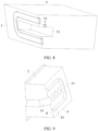
FIG. 8 is a schematic diagram of a structure of the loudspeaker inFIG. 6 in which a flexible sealing member is mounted; -
FIG. 9 is a schematic diagram of a structure of the middle frame inFIG. 6 ; and -
FIG. 10 is a schematic diagram of a structure of the middle frame inFIG. 6 in which a dust filter is mounted. - Description of reference numerals in
FIG. 1 to FIG. 10 :
1: body portion; 2: middle frame; 3: battery compartment; 4: loudspeaker; 5: first mating surface; 51: first channel; 52: mounting groove; 53: first adhesive layer; 54: limiting structure; 6: second mating surface; 61: second channel; 7: flexible sealing member; 8: rigid sealing member; 81: arc structure; 9: sound output channel; and 10: dust filter. - To enable a person skilled in the art to better understand the technical solutions of this application, the following describes this application in further detail with reference to the accompanying drawings and specific embodiments.
- An electronic device provided in an embodiment of this application may be a mobile phone or a tablet computer, or may be a handheld computer, a walkie-talkie, a POS machine, an event data recorder, a wearable device, a virtual reality device, or in-vehicle original equipment or another terminal product with a loudspeaker.
- The electronic device provided in this embodiment of this application includes a body portion and a loudspeaker. The body portion is provided with a mounting cavity for mounting the loudspeaker. The mounting cavity resembles a groove structure. During mounting, the loudspeaker is placed into the groove structure from outside in along a depth direction of the mounting cavity.
- Specifically, an inner wall of the mounting cavity and the loudspeaker each are provided with a mating surface, and the mating surfaces are respectively provided channels capable of being mutually connected. In other words, after the loudspeaker is mounted in the mounting cavity, the mating surface of the mounting cavity is mated with the mating surface of the loudspeaker, and the channel of the mounting cavity is connected to the channel of the loudspeaker to form a sound output channel, so that a sound can be transmitted.
- As shown in
FIG. 1 , for example, the electronic device is a mobile phone. A body portion 1 of the mobile phone includes amiddle frame 2 and abattery compartment 3. The mounting cavity is enclosed by an inner wall of themiddle frame 2 and an outer wall of thebattery compartment 3. A sidewall surface of themiddle frame 2 that faces the inside of the mounting cavity forms a mating surface. Aloudspeaker 4 is correspondingly provided with a mating surface. A size of the mounting cavity adapts to a size of theloudspeaker 4. After theloudspeaker 4 is mounted in the mounting cavity, the mating surface of theloudspeaker 4 can be mated with the mating surface of themiddle frame 2, and a side end face of theloudspeaker 4 that is away from the mating surface can abut against and be mated with a sidewall surface of the mounting cavity that faces thebattery compartment 3, thereby ensuring that theloudspeaker 4 can be stably located in the mounting cavity. - For ease of description, the two mating surfaces are respectively referred to as a
first mating surface 5 and asecond mating surface 6. As shown inFIG. 2 andFIG. 6 , thefirst mating surface 5 is provided with afirst channel 51, and thesecond mating surface 6 is provided with asecond channel 61. When the two mating surfaces are mated, thefirst channel 51 is connected to thesecond channel 61 to form asound output channel 9. Specifically, the mating surface of themiddle frame 2 forms thefirst mating surface 5 and the mating surface of theloudspeaker 4 forms thesecond mating surface 6, or the mating surface of themiddle frame 2 forms thesecond mating surface 6 and the mating surface of theloudspeaker 4 forms thefirst mating surface 5. After assembly, the two mating surfaces can be mated and be relatively fixed, thesound output channel 9 is formed after thechannel 51 andchannel 61 are connected, and a sealing portion can implement sealing along a circumferential direction at a connection joint of thesound output channel 9, to prevent external liquid or dust from entry. - In detail, the sealing portion includes a
flexible sealing member 7 and arigid sealing member 8. Theflexible sealing member 7 is provided on thefirst mating surface 5 and arranged along a circumferential direction of thefirst channel 51. Therigid sealing member 8 is fixedly provided on thesecond mating surface 6 and arranged along a circumferential direction of thesecond channel 61. During mounting, thefirst mating surface 5 and thesecond mating surface 6 can slide relative to each other, until thefirst channel 51 and thesecond channel 61 are correspondingly connected, and the corresponding flexible sealingmember 7 andrigid sealing member 8 abut against and are mated with each other. In this case, theflexible sealing member 7 and therigid sealing member 8 can implement sealing along the circumferential directions of thefirst channel 51 and thesecond channel 61, thereby completing assembly. - Literally, it can be easily understood that, a material of the
flexible sealing member 7 is comparatively soft, and a silicone sealing gasket may be selected as theflexible sealing member 7. The silicone sealing gasket features some elasticity, low costs, and good economic efficiency. A material of therigid sealing member 8 is comparatively hard. Specifically, plastic, metal, or the like may be selected as therigid sealing member 8. When theflexible sealing member 7 is mated with therigid sealing member 8, therigid sealing member 8 can squeeze theflexible sealing member 7, so that theflexible sealing member 7 is deformed to implement sealing along the circumferential direction at the connection joint of thesound output channel 9. Specifically, the silicone sealing gasket is an annular structure arranged along the circumferential direction of thefirst channel 51. Therigid sealing member 8 is an annular convex rib provided on thesecond mating surface 6. The annular convex rib adapts to the silicone sealing gasket. After the annular convex rib abuts against and is mated with the silicone sealing gasket, the annular convex rib can squeeze the silicone sealing gasket to elastically deform the silicone sealing gasket, thereby ensuring sealing performance. - During mounting, the
loudspeaker 4 is mounted in the mounting cavity from outside in along a depth direction of the mounting cavity. In this process, the mating surface of theloudspeaker 4 can move relative to the mating surface of themiddle frame 2. After theloudspeaker 4 is mounted in place, theflexible sealing member 7 between the two mating surfaces can be mated with therigid sealing member 8 in a sealing manner. Therefore, in the mounting process, as the two mating surfaces slide relative to each other, more or less relative fitting and sliding exist between theflexible sealing member 7 and therigid sealing member 8 before the mating. For ease of description, in the mounting process, a direction in which therigid sealing member 8 moves relative to theflexible sealing member 7 is referred to as a first direction. - Specifically, moving directions of the
first mating surface 5 and thesecond mating surface 6 are opposite. As shown inFIG. 2 , when the mating surface of themiddle frame 2 forms thefirst mating surface 5 and is provided with theflexible sealing member 7, and the mating surface of theloudspeaker 4 forms thesecond mating surface 6 and is provided with therigid sealing member 8, thefirst mating surface 5 and theflexible sealing member 7 do not move during mounting, while thesecond mating surface 6 drives therigid sealing member 8 to move towards the inside of the mounting cavity relative to thefirst mating surface 5. In this case, the first direction refers to a direction from outside in along the depth direction of the mounting cavity. With the mounting of theloudspeaker 4, therigid sealing member 8 has a tendency to scratch theflexible sealing member 7 and make theflexible sealing member 7 move towards an inner side of the mounting cavity relative to thefirst mating surface 5. As shown inFIG. 6 , when the mating surface of themiddle frame 2 forms thesecond mating surface 6 and is provided with therigid sealing member 8, and the mating surface of theloudspeaker 4 forms thefirst mating surface 5 and is provided with theflexible sealing member 7, thesecond mating surface 6 and therigid sealing member 8 do not move during mounting, and thefirst mating surface 5 drives theflexible sealing member 7 to move relative to thesecond mating surface 6. In this case, the first direction refers to a direction from inside out along the depth direction of the mounting cavity. With the mounting of theloudspeaker 4, therigid sealing member 8 has a tendency to scratch theflexible sealing member 7 and make theflexible sealing member 7 move towards an outer side of the mounting cavity relative to thefirst mating surface 5. - If the
rigid sealing member 8 scratches theflexible sealing member 7 in a relative fitting and sliding process before mating between theflexible sealing member 7 and therigid sealing member 8, a mating failure occurs due to displacement of theflexible sealing member 7. To prevent this case, in this embodiment, as shown inFIG. 3 andFIG. 7 , thefirst mating surface 5 is provided with a mountinggroove 52, the mountinggroove 52 is arranged along the circumferential direction of thefirst channel 51, and the mountinggroove 52 is configured to mount theflexible sealing member 7. Specifically, when the first direction is the direction from outside in along the depth direction of the mounting cavity, as shown inFIG. 3 , a sidewall of the mountinggroove 52 that faces an inner side along the depth direction of the mounting cavity forms a limitingstructure 54. As shown inFIG. 4 , when theflexible sealing member 7 is mounted in the mountinggroove 52, the limitingstructure 54 can restrict theflexible sealing member 7 from moving relative to thefirst mating surface 5. This ensures location stability of theflexible sealing member 7 in the mounting process of theloudspeaker 4 and ensures that theflexible sealing member 7 and therigid sealing member 8 can be mated after theloudspeaker 4 is mounted in place. When the first direction is the direction from inside out along the depth direction of the mounting cavity, as shown inFIG. 7 , a sidewall of the mountinggroove 52 that faces an outer side along the depth direction of the mounting cavity forms a limitingstructure 54. As shown inFIG. 8 , when theflexible sealing member 7 is mounted in the mountinggroove 52, the limitingstructure 54 can restrict theflexible sealing member 7 from moving relative to thefirst mating surface 5. This ensures location stability of theflexible sealing member 7 in the mounting process of theloudspeaker 4 and ensures that theflexible sealing member 7 and therigid sealing member 8 can be mated after theloudspeaker 4 is mounted in place. - In addition, as shown in
FIG. 2 andFIG. 6 , the mating surface of themiddle frame 2 and the mating surface of theloudspeaker 4 are both inclined surfaces that adapt to each other. Specifically, a top end (an end facing an opening of the mounting cavity) of the mating surface of themiddle frame 2 is inclined towards an outer side of the mounting cavity. In other words, a cross-sectional area of an opening end of the mounting cavity is greater than a cross-sectional area of a bottom end. In this way, when theloudspeaker 4 is mounted, as a space at the opening end is large, at first the mating surface of theloudspeaker 4 is not in contact with the mating surface of themiddle frame 2. In addition, before theloudspeaker 4 is mounted in place, there is still a gap between the mating surface of theloudspeaker 4 and the mating surface of themiddle frame 2, and therigid sealing member 8 and theflexible sealing member 7 are not fully mated. This arrangement enables smooth mounting of theloudspeaker 4, and reduces contact sliding between the two mating surfaces and between therigid sealing member 8 and theflexible sealing member 7, thereby reducing an acting force applied by therigid sealing member 8 to scratch theflexible sealing member 7, and facilitating the mounting operations while ensuring a sealing protection effect after the mounting. - Therefore, in the electronic device provided in this embodiment, when the
loudspeaker 4 is mounted in the mounting cavity, theloudspeaker 4 can be directly mounted from outside in along the depth direction of the mounting cavity. Theloudspeaker 4 does not need to be inclined, and the mounting operations are convenient. In addition, with the arrangement of the limitingstructure 54, relative locations of theflexible sealing member 7 and thefirst mating surface 5 can be prevented from changes caused by scratching in a mounting process. This ensures a sealing protection effect after mounting is completed, requires no structural change of theloudspeaker 4, and ensures a sound output effect of the electronic device. - A depth of the mounting
groove 52 is not less than a thickness of theflexible sealing member 7, in other words, the entire flexible sealingmember 7 is located in the mountinggroove 52 and does not protrude from thefirst mating surface 5, and therigid sealing member 8 protrudes from thesecond mating surface 6. During mounting, since theflexible sealing member 7 does not protrude from thefirst mating surface 5, when therigid sealing member 8 slides along thefirst mating surface 5, therigid sealing member 8 does not scratch theflexible sealing member 7, until the two mating surfaces move relative to each other in place, and therigid sealing member 8 is mated with theflexible sealing member 7. In this case, a side end of therigid sealing member 8 that faces thefirst mating surface 5 can just enter the mountinggroove 52 and abut against and be mated with theflexible sealing member 7, thereby ensuring a sealing effect. - When the two mating surfaces are mated, the side end of the
rigid sealing member 8 that faces thefirst mating surface 5 may partially enter the mountinggroove 52 and abut against and be mated with theflexible sealing member 7. In this case, a gap may be left between the two mating surfaces. Alternatively, when the two mating surfaces are mated, therigid sealing member 8 may fully enter the mountinggroove 52 and abut against and be mated with theflexible sealing member 7. In this case, the two mating surfaces fit with each other. - In this embodiment, the depth of the mounting
groove 52 may alternatively be less than the thickness of theflexible sealing member 7. In this case, a portion of theflexible sealing member 7 protrudes out of the mountinggroove 52, that is, a portion of theflexible sealing member 7 protrudes from thefirst mating surface 5. During mounting, when therigid sealing member 8 slides relative to thefirst mating surface 5, therigid sealing member 8 can scratch theflexible sealing member 7 protruding from thefirst mating surface 5. Nevertheless, due to a limiting function of a groove wall of the mountinggroove 52, theflexible sealing member 7 is not displaced at a location of thefirst mating surface 5, and the sealing protection effect after mounting in place can be ensured. - Alternatively, in this embodiment, the foregoing limiting
structure 54 may be formed by providing a stopper (not shown in the figure) on thefirst mating surface 5. The stopper is specifically provided on a side of theflexible sealing member 7 that faces the first direction. When the first direction is outside in along the depth direction of the mounting cavity, the stopper is provided on a side of theflexible sealing member 7 that faces the inside of the mounting cavity. When the first direction is from inside out along the depth direction of the mounting cavity, the stopper is provided on a side of theflexible sealing member 7 that faces the outside of the mounting cavity. Specifically, the stopper may be protruding structures spaced apart or may be a continuous protruding structure, provided that the stopper can restrict theflexible sealing member 7 from being displaced at the location of thefirst mating surface 5 when being scratched by therigid sealing member 8. - The arrangement of the mounting
groove 52 can simplify an overall structure when compared with the arrangement of the stopper. When the entire flexible sealingmember 7 is arranged in the mountinggroove 52, in a process of mounting theloudspeaker 4, therigid sealing member 8 and theflexible sealing member 7 do not scratch each other before being mated. This ensures location stability of theflexible sealing member 7, and can further reduce mounting resistance between thefirst mating surface 5 and thesecond mating surface 6, thereby facilitating the mounting operations of theloudspeaker 4. - As shown in
FIG. 4 andFIG. 8 , theflexible sealing member 7 is adhesively fastened to an inner wall (a sidewall and/or a bottom wall) of the mountinggroove 52 by using a firstadhesive layer 53. In other words, theflexible sealing member 7 is adhesively fastened in the mountinggroove 52. This can further ensure that theflexible sealing member 7 can be stably located in the mountinggroove 52, thereby further ensuring mounting stability. If the limitingstructure 54 is a stopper provided on thefirst mating surface 5, theflexible sealing member 7 may also be adhesively fastened to the stopper and/or theflexible sealing member 7 may also be adhesively fastened to thefirst mating surface 5 by using the firstadhesive layer 53, to ensure stability of theflexible sealing member 7. - Alternatively, the
flexible sealing member 7 may be directly placed in the mountinggroove 52. When the depth of the mountinggroove 52 is not less than the thickness of theflexible sealing member 7, the entire flexible sealingmember 7 can be located in the mountinggroove 52. There may be no other connection manner between theflexible sealing member 7 and the mountinggroove 52. When the firstadhesive layer 53 is used for adhesive fastening, the stability of theflexible sealing member 7 in the mountinggroove 52 can be further ensured. - Certainly, in this embodiment, a manner of fastening the
flexible sealing member 7 is not limited. For example, theflexible sealing member 7 may also be fastened to thefirst mating surface 5 by using a fastener. The adhesive fastening using the firstadhesive layer 53 can simplify the overall structure and the mounting operations, and can further ensure a sealing effect between thefirst mating surface 5 and theflexible sealing member 7. - The rigid sealing member 8 (the annular convex rib) may be fastened to the
second mating surface 6 by using a fastener, or may be adhesively fastened to thesecond mating surface 6. Alternatively, as shown inFIG. 5 andFIG. 9 , the annular convex rib and thesecond mating surface 6 are an integrated structure. This simplifies the overall structure, simplifies a machining process, and further ensures stability of the fastening between the annular convex rib and thesecond mating surface 6, thereby avoiding displacement of the annular convex rib at a location of thesecond mating surface 6 during relative movement of the two mating surfaces, and further simplifying an assembly process and improving assembly efficiency. - A side end of the annular convex rib that faces the
first mating surface 5 can abut against the flexible sealing member 7 (the silicone sealing gasket) and elastically deform theflexible sealing member 7. Therefore, as shown inFIG. 5 andFIG. 9 , the side end of the annular convex rib that faces thefirst mating surface 5 is asmooth arc structure 81. This arrangement can avoid damage to theflexible sealing member 7 when the annular convex rib abuts against theflexible sealing member 7. - In addition, a cross section of the annular convex rib tapers from a side of the
second mating surface 6 to a side of thefirst mating surface 5. In other words, a side of the cross section of the annular convex rib that faces thefirst mating surface 5 has a smaller width. Specifically, the cross section of the annular convex rib may be provided as a triangular structure, as shown inFIG. 5 andFIG. 9 . One side of the triangular structure faces the second mating surface 6 (specifically, fitting and fastening or an integrated structure may be used), and an outer wall of a corner corresponding to the side is thesmooth arc structure 81 and can abut against theflexible sealing member 7. Alternatively, the cross section of the annular convex rib may be provided as a trapezoidal structure, where a long side thereof is fitted with thesecond mating surface 6, and a short side thereof can form the smoothtransitional arc structure 81 and can also abut against theflexible sealing member 7. When the end of the annular convex rib that faces thefirst mating surface 5 has a smaller width, an abutment area between the end and theflexible sealing member 7 can be reduced, and a deformation amount of theflexible sealing member 7 can be increased, thereby ensuring a sealing effect. - Specific structures of the
first channel 51 and thesecond channel 61 are not limited. For example, each of the two channels may be provided with only one hole structure, or either of them may be provided with a plurality of hole structures, or both may be provided with a plurality of hole structures. Regardless of a quantity of hole structures provided in each channel, the two channels are correspondingly connected to each other to form thesound output channel 9. The entiresound output channel 9 is located in an annular structure enclosed by the sealing portion, thereby ensuring an overall sealing protection effect. When the two mating surfaces are mated, a hole structure of themiddle frame 2 can be connected to a hole structure of theloudspeaker 4 to form thesound output channel 9. The sealing portion can be provided in a sealing manner along a whole outer periphery of thesound output channel 9. As shown inFIG. 9 , when a plurality of hole structures are provided in the channel of themiddle frame 2, all the hole structures are located in the annular structure enclosed by the sealing portion, thereby ensuring the overall sealing protection effect. - A
dust filter 10 is further provided between thefirst mating surface 5 and thesecond mating surface 6. Thedust filter 10 can block the channel provided on the inner wall of the mounting cavity. As shown inFIG. 4 , thedust filter 10 is fastened to thefirst mating surface 5 by using a second adhesive layer and blocks thefirst channel 51. As shown inFIG. 10 , thedust filter 10 is fastened to thesecond mating surface 6 by using a second adhesive layer and blocks thesecond channel 61. It can be easily understood that, thedust filter 10 is a mesh structure, and can block thesound output channel 9 without affecting the sound output effect of thesound output channel 9. Thedust filter 10 can play a dust-proof function on thesound output channel 9, and prevent dust outside thefirst channel 51 of themiddle frame 2 from entering thesound output channel 9, thereby protecting theloudspeaker 4. Certainly, in this embodiment, a specific fastening manner of thedust filter 10 is not limited. For example, thedust filter 10 may be fastened by using a fastener to a mating surface formed on a corresponding inner wall of the mounting cavity, while adhesive fastening using the second adhesive layer can simplify the overall structure and the mounting technology. - The foregoing is merely example implementations of this application. It should be noted that, a person of ordinary skill in the art can further make some improvements and modifications without departing from the principles of this application, and the improvements and modifications shall fall within the protection scope of this application.
Claims (11)
- An electronic device, comprising a body portion (1) and a loudspeaker (4), wherein the body portion (1) is provided with a mounting cavity for mounting the loudspeaker (4), an inner wall of the mounting cavity and the loudspeaker (4) each are correspondingly provided with a mating surface, and the mating surfaces are respectively provided channels capable of being mutually connected; and
the two mating surfaces are respectively a first mating surface (5) and a second mating surface (6), the first mating surface (5) is provided with a limiting structure (54) and a flexible sealing member (7) provided along a circumferential direction of the channel, the second mating surface (6) is provided with a rigid sealing member (8) provided along a circumferential direction of the channel, the two mating surfaces are capable of moving relative to each other so that the rigid sealing member (8) is mated with the flexible sealing member (7) in a sealing manner, the limiting structure (54) is configured to restrict the flexible sealing member (7) from moving relative to the first mating surface (5) along a first direction, and the first direction is a direction along which the rigid sealing member (8) moves relative to the flexible sealing member (7). - The electronic device according to claim 1, wherein the first mating surface (5) is provided with a mounting groove (52), the flexible sealing member (7) is provided in the mounting groove (52), and a groove wall of the mounting groove (52) forms the limiting structure (54).
- The electronic device according to claim 2, wherein a depth of the mounting groove (52) is not less than a thickness of the flexible sealing member (7), and the rigid sealing member (8) protrudes from the second mating surface (6).
- The electronic device according to claim 2, wherein the flexible sealing member (7) is adhesively fastened to an inner wall of the mounting groove (52) by using a first adhesive layer (53).
- The electronic device according to any one of claims 1 to 4, wherein the flexible sealing member (7) is a silicone sealing gasket.
- The electronic device according to any one of claims 1 to 4, wherein the second mating surface (6) is integrally formed with an annular convex rib, and the annular convex rib forms the rigid sealing member (8).
- The electronic device according to claim 6, wherein a side end of the annular convex rib that faces the first mating surface (5) is a smooth arc structure (81).
- The electronic device according to claim 7, wherein a cross section of the annular convex rib tapers from a side of the second mating surface (6) to a side of the first mating surface (5).
- The electronic device according to any one of claims 1 to 8, further comprising a dust filter (10) provided between the first mating surface (5) and the second mating surface (6), wherein the dust filter (10) is capable of blocking the channel provided on the inner wall of the mounting cavity.
- The electronic device according to claim 9, wherein the dust filter (10) is adhesively fastened to the mating surface on the inner wall of the mounting cavity by using a second adhesive layer.
- The electronic device according to any one of claims 1 to 10, wherein the mating surface of the mounting cavity and the mating surface of the loudspeaker (4) are both inclined surfaces that adapt to each other, and an end of the mating surface of the mounting cavity that faces an opening is inclined towards the outside of the mounting cavity.
Applications Claiming Priority (2)
| Application Number | Priority Date | Filing Date | Title |
|---|---|---|---|
| CN202111112843.7A CN115002261B (en) | 2021-09-18 | 2021-09-18 | Electronic equipment |
| PCT/CN2022/117458 WO2023040715A1 (en) | 2021-09-18 | 2022-09-07 | Electronic device |
Publications (3)
| Publication Number | Publication Date |
|---|---|
| EP4207723A1 true EP4207723A1 (en) | 2023-07-05 |
| EP4207723A4 EP4207723A4 (en) | 2024-04-10 |
| EP4207723B1 EP4207723B1 (en) | 2025-02-12 |
Family
ID=83018633
Family Applications (1)
| Application Number | Title | Priority Date | Filing Date |
|---|---|---|---|
| EP22865891.0A Active EP4207723B1 (en) | 2021-09-18 | 2022-09-07 | Electronic device |
Country Status (4)
| Country | Link |
|---|---|
| US (1) | US12353251B2 (en) |
| EP (1) | EP4207723B1 (en) |
| CN (1) | CN115002261B (en) |
| WO (1) | WO2023040715A1 (en) |
Families Citing this family (1)
| Publication number | Priority date | Publication date | Assignee | Title |
|---|---|---|---|---|
| CN115002261B (en) * | 2021-09-18 | 2023-04-11 | 荣耀终端有限公司 | Electronic equipment |
Family Cites Families (28)
| Publication number | Priority date | Publication date | Assignee | Title |
|---|---|---|---|---|
| US9795044B2 (en) * | 2011-08-22 | 2017-10-17 | Catalyst Lifestyle Limited | Waterproof case |
| US8989428B2 (en) * | 2011-08-31 | 2015-03-24 | Apple Inc. | Acoustic systems in electronic devices |
| CN103517165A (en) * | 2012-06-27 | 2014-01-15 | 比亚迪股份有限公司 | Loudspeaker sound cavity structure and mobile terminal using same |
| US20140376758A1 (en) * | 2013-06-19 | 2014-12-25 | Matthew Barcel | Universal protective housing and sound system |
| CN204697267U (en) | 2015-05-18 | 2015-10-07 | Tcl通力电子(惠州)有限公司 | Fixing structure for horn and sound equipment |
| CN105828548B (en) | 2015-11-16 | 2019-04-12 | 维沃移动通信有限公司 | A kind of electronic equipment |
| CN106686506A (en) | 2017-02-24 | 2017-05-17 | 上海与德信息技术有限公司 | Loudspeaker |
| CN206894832U (en) * | 2017-06-29 | 2018-01-16 | 深圳天珑无线科技有限公司 | Speaker seal component and mobile terminal |
| CN207968771U (en) * | 2018-03-08 | 2018-10-12 | 维沃移动通信有限公司 | A kind of sound cavity sealing structure and mobile terminal |
| KR102533426B1 (en) | 2018-05-03 | 2023-05-17 | 삼성전자 주식회사 | Conduit of electronic device and the electronic device comprising the same |
| CN110491285B (en) | 2018-05-14 | 2021-11-05 | Oppo广东移动通信有限公司 | Foldable screens and electronics |
| CN108508979A (en) | 2018-06-29 | 2018-09-07 | 合肥联宝信息技术有限公司 | Electronic equipment |
| CN208723945U (en) * | 2018-07-16 | 2019-04-09 | Oppo广东移动通信有限公司 | Electronic equipment |
| CN209375910U (en) * | 2018-11-28 | 2019-09-10 | 歌尔科技有限公司 | A kind of loudspeaker |
| WO2020118065A1 (en) | 2018-12-05 | 2020-06-11 | Oda Inc. | Speaker |
| US10827249B1 (en) * | 2019-06-27 | 2020-11-03 | Amazon Technologies, Inc. | Wireless earbud |
| CN110572752B (en) | 2019-08-20 | 2022-04-19 | 歌尔股份有限公司 | Acoustic device and electronic apparatus |
| CN210274426U (en) * | 2019-09-03 | 2020-04-07 | 广东虹勤通讯技术有限公司 | Upper shell of electronic equipment and electronic equipment |
| CN210745477U (en) * | 2019-11-22 | 2020-06-12 | 江苏裕成电子有限公司 | Loudspeaker sealing member |
| CN113014696B (en) | 2019-12-20 | 2023-08-01 | 中兴通讯股份有限公司 | Folding terminal structure |
| EP4395289B1 (en) | 2019-12-27 | 2026-02-04 | Huawei Technologies Co., Ltd. | Electronic device |
| CN212061687U (en) | 2020-01-20 | 2020-12-01 | 华为技术有限公司 | Electronic device |
| US12348923B2 (en) * | 2020-08-10 | 2025-07-01 | Google Llc | Systems, device assemblies, and methods for achieving acoustic seal and ingress protection |
| CN111968513B (en) | 2020-08-28 | 2022-04-12 | 维沃移动通信有限公司 | Electronic device |
| CN213638129U (en) | 2020-09-24 | 2021-07-06 | 上海闻泰电子科技有限公司 | Radio sealing structure and electronic products |
| CN213305455U (en) | 2020-09-24 | 2021-05-28 | 上海闻泰电子科技有限公司 | Rubber sleeve sealing structure and electronic products |
| CN112616099B (en) * | 2020-12-18 | 2023-06-23 | 维沃移动通信有限公司 | Electronic equipment |
| CN115002261B (en) * | 2021-09-18 | 2023-04-11 | 荣耀终端有限公司 | Electronic equipment |
-
2021
- 2021-09-18 CN CN202111112843.7A patent/CN115002261B/en active Active
-
2022
- 2022-09-07 WO PCT/CN2022/117458 patent/WO2023040715A1/en not_active Ceased
- 2022-09-07 EP EP22865891.0A patent/EP4207723B1/en active Active
- 2022-09-07 US US18/246,402 patent/US12353251B2/en active Active
Also Published As
| Publication number | Publication date |
|---|---|
| CN115002261A (en) | 2022-09-02 |
| CN115002261B (en) | 2023-04-11 |
| EP4207723B1 (en) | 2025-02-12 |
| EP4207723A4 (en) | 2024-04-10 |
| US12353251B2 (en) | 2025-07-08 |
| WO2023040715A1 (en) | 2023-03-23 |
| US20230359251A1 (en) | 2023-11-09 |
Similar Documents
| Publication | Publication Date | Title |
|---|---|---|
| JP7089016B2 (en) | Mobile terminal and camera assembly | |
| CN1979277B (en) | Image display system and liquid crystal display module thereof | |
| EP4354833A1 (en) | Electronic device | |
| EP2640174A2 (en) | Electronic device and sealed structure | |
| EP4002827B1 (en) | Electronic device | |
| US12353251B2 (en) | Electronic device | |
| US20230324961A1 (en) | Electronic device | |
| KR20220157469A (en) | electronic device | |
| EP4401391A1 (en) | Frame, and electronic device | |
| CN110177157B (en) | Housing components and electronic equipment | |
| CN110460704A (en) | A kind of electronic equipment | |
| CN211406056U (en) | Electronic equipment | |
| JP6561705B2 (en) | Information processing device | |
| CN215735394U (en) | Electronic device | |
| JP5045910B2 (en) | Seal structure of electronic equipment | |
| CN110557483A (en) | Telescopic mechanism and mobile terminal | |
| CN215734507U (en) | Camera module and electronic equipment | |
| CN207460300U (en) | Electronic device | |
| EP4132239A1 (en) | Electronic device | |
| HK40074388B (en) | Electronic device | |
| CN209897468U (en) | Sealed structure and electronic equipment | |
| JP2011259279A (en) | Portable electronic device | |
| HK40074388A (en) | Electronic device | |
| US8554290B2 (en) | Portable electronic apparatus having casings | |
| CN221804669U (en) | Keyboard |
Legal Events
| Date | Code | Title | Description |
|---|---|---|---|
| STAA | Information on the status of an ep patent application or granted ep patent |
Free format text: STATUS: UNKNOWN |
|
| STAA | Information on the status of an ep patent application or granted ep patent |
Free format text: STATUS: THE INTERNATIONAL PUBLICATION HAS BEEN MADE |
|
| PUAI | Public reference made under article 153(3) epc to a published international application that has entered the european phase |
Free format text: ORIGINAL CODE: 0009012 |
|
| STAA | Information on the status of an ep patent application or granted ep patent |
Free format text: STATUS: REQUEST FOR EXAMINATION WAS MADE |
|
| 17P | Request for examination filed |
Effective date: 20230314 |
|
| AK | Designated contracting states |
Kind code of ref document: A1 Designated state(s): AL AT BE BG CH CY CZ DE DK EE ES FI FR GB GR HR HU IE IS IT LI LT LU LV MC MK MT NL NO PL PT RO RS SE SI SK SM TR |
|
| A4 | Supplementary search report drawn up and despatched |
Effective date: 20240307 |
|
| RIC1 | Information provided on ipc code assigned before grant |
Ipc: H04R 1/02 20060101ALI20240301BHEP Ipc: H04M 1/18 20060101ALI20240301BHEP Ipc: H04M 1/03 20060101AFI20240301BHEP |
|
| GRAP | Despatch of communication of intention to grant a patent |
Free format text: ORIGINAL CODE: EPIDOSNIGR1 |
|
| STAA | Information on the status of an ep patent application or granted ep patent |
Free format text: STATUS: GRANT OF PATENT IS INTENDED |
|
| DAV | Request for validation of the european patent (deleted) | ||
| DAX | Request for extension of the european patent (deleted) | ||
| INTG | Intention to grant announced |
Effective date: 20240920 |
|
| GRAS | Grant fee paid |
Free format text: ORIGINAL CODE: EPIDOSNIGR3 |
|
| GRAA | (expected) grant |
Free format text: ORIGINAL CODE: 0009210 |
|
| STAA | Information on the status of an ep patent application or granted ep patent |
Free format text: STATUS: THE PATENT HAS BEEN GRANTED |
|
| AK | Designated contracting states |
Kind code of ref document: B1 Designated state(s): AL AT BE BG CH CY CZ DE DK EE ES FI FR GB GR HR HU IE IS IT LI LT LU LV MC MK MT NL NO PL PT RO RS SE SI SK SM TR |
|
| REG | Reference to a national code |
Ref country code: GB Ref legal event code: FG4D |
|
| REG | Reference to a national code |
Ref country code: CH Ref legal event code: EP |
|
| REG | Reference to a national code |
Ref country code: DE Ref legal event code: R096 Ref document number: 602022010641 Country of ref document: DE |
|
| REG | Reference to a national code |
Ref country code: IE Ref legal event code: FG4D Ref country code: NL Ref legal event code: FP |
|
| PG25 | Lapsed in a contracting state [announced via postgrant information from national office to epo] |
Ref country code: RS Free format text: LAPSE BECAUSE OF FAILURE TO SUBMIT A TRANSLATION OF THE DESCRIPTION OR TO PAY THE FEE WITHIN THE PRESCRIBED TIME-LIMIT Effective date: 20250512 |
|
| PG25 | Lapsed in a contracting state [announced via postgrant information from national office to epo] |
Ref country code: FI Free format text: LAPSE BECAUSE OF FAILURE TO SUBMIT A TRANSLATION OF THE DESCRIPTION OR TO PAY THE FEE WITHIN THE PRESCRIBED TIME-LIMIT Effective date: 20250212 |
|
| PG25 | Lapsed in a contracting state [announced via postgrant information from national office to epo] |
Ref country code: PL Free format text: LAPSE BECAUSE OF FAILURE TO SUBMIT A TRANSLATION OF THE DESCRIPTION OR TO PAY THE FEE WITHIN THE PRESCRIBED TIME-LIMIT Effective date: 20250212 |
|
| PG25 | Lapsed in a contracting state [announced via postgrant information from national office to epo] |
Ref country code: ES Free format text: LAPSE BECAUSE OF FAILURE TO SUBMIT A TRANSLATION OF THE DESCRIPTION OR TO PAY THE FEE WITHIN THE PRESCRIBED TIME-LIMIT Effective date: 20250212 |
|
| REG | Reference to a national code |
Ref country code: LT Ref legal event code: MG9D |
|
| PG25 | Lapsed in a contracting state [announced via postgrant information from national office to epo] |
Ref country code: IS Free format text: LAPSE BECAUSE OF FAILURE TO SUBMIT A TRANSLATION OF THE DESCRIPTION OR TO PAY THE FEE WITHIN THE PRESCRIBED TIME-LIMIT Effective date: 20250612 Ref country code: NO Free format text: LAPSE BECAUSE OF FAILURE TO SUBMIT A TRANSLATION OF THE DESCRIPTION OR TO PAY THE FEE WITHIN THE PRESCRIBED TIME-LIMIT Effective date: 20250512 |
|
| PG25 | Lapsed in a contracting state [announced via postgrant information from national office to epo] |
Ref country code: HR Free format text: LAPSE BECAUSE OF FAILURE TO SUBMIT A TRANSLATION OF THE DESCRIPTION OR TO PAY THE FEE WITHIN THE PRESCRIBED TIME-LIMIT Effective date: 20250212 |
|
| PG25 | Lapsed in a contracting state [announced via postgrant information from national office to epo] |
Ref country code: PT Free format text: LAPSE BECAUSE OF FAILURE TO SUBMIT A TRANSLATION OF THE DESCRIPTION OR TO PAY THE FEE WITHIN THE PRESCRIBED TIME-LIMIT Effective date: 20250612 Ref country code: LV Free format text: LAPSE BECAUSE OF FAILURE TO SUBMIT A TRANSLATION OF THE DESCRIPTION OR TO PAY THE FEE WITHIN THE PRESCRIBED TIME-LIMIT Effective date: 20250212 |
|
| PG25 | Lapsed in a contracting state [announced via postgrant information from national office to epo] |
Ref country code: BG Free format text: LAPSE BECAUSE OF FAILURE TO SUBMIT A TRANSLATION OF THE DESCRIPTION OR TO PAY THE FEE WITHIN THE PRESCRIBED TIME-LIMIT Effective date: 20250212 Ref country code: GR Free format text: LAPSE BECAUSE OF FAILURE TO SUBMIT A TRANSLATION OF THE DESCRIPTION OR TO PAY THE FEE WITHIN THE PRESCRIBED TIME-LIMIT Effective date: 20250513 |
|
| REG | Reference to a national code |
Ref country code: AT Ref legal event code: MK05 Ref document number: 1767195 Country of ref document: AT Kind code of ref document: T Effective date: 20250212 |
|
| PG25 | Lapsed in a contracting state [announced via postgrant information from national office to epo] |
Ref country code: SE Free format text: LAPSE BECAUSE OF FAILURE TO SUBMIT A TRANSLATION OF THE DESCRIPTION OR TO PAY THE FEE WITHIN THE PRESCRIBED TIME-LIMIT Effective date: 20250212 |
|
| PGFP | Annual fee paid to national office [announced via postgrant information from national office to epo] |
Ref country code: NL Payment date: 20250814 Year of fee payment: 4 |
|
| PG25 | Lapsed in a contracting state [announced via postgrant information from national office to epo] |
Ref country code: SM Free format text: LAPSE BECAUSE OF FAILURE TO SUBMIT A TRANSLATION OF THE DESCRIPTION OR TO PAY THE FEE WITHIN THE PRESCRIBED TIME-LIMIT Effective date: 20250212 |
|
| PG25 | Lapsed in a contracting state [announced via postgrant information from national office to epo] |
Ref country code: DK Free format text: LAPSE BECAUSE OF FAILURE TO SUBMIT A TRANSLATION OF THE DESCRIPTION OR TO PAY THE FEE WITHIN THE PRESCRIBED TIME-LIMIT Effective date: 20250212 |
|
| PGFP | Annual fee paid to national office [announced via postgrant information from national office to epo] |
Ref country code: DE Payment date: 20250730 Year of fee payment: 4 |
|
| PG25 | Lapsed in a contracting state [announced via postgrant information from national office to epo] |
Ref country code: IT Free format text: LAPSE BECAUSE OF FAILURE TO SUBMIT A TRANSLATION OF THE DESCRIPTION OR TO PAY THE FEE WITHIN THE PRESCRIBED TIME-LIMIT Effective date: 20250212 |
|
| PG25 | Lapsed in a contracting state [announced via postgrant information from national office to epo] |
Ref country code: AT Free format text: LAPSE BECAUSE OF FAILURE TO SUBMIT A TRANSLATION OF THE DESCRIPTION OR TO PAY THE FEE WITHIN THE PRESCRIBED TIME-LIMIT Effective date: 20250212 |
|
| PG25 | Lapsed in a contracting state [announced via postgrant information from national office to epo] |
Ref country code: EE Free format text: LAPSE BECAUSE OF FAILURE TO SUBMIT A TRANSLATION OF THE DESCRIPTION OR TO PAY THE FEE WITHIN THE PRESCRIBED TIME-LIMIT Effective date: 20250212 Ref country code: CZ Free format text: LAPSE BECAUSE OF FAILURE TO SUBMIT A TRANSLATION OF THE DESCRIPTION OR TO PAY THE FEE WITHIN THE PRESCRIBED TIME-LIMIT Effective date: 20250212 |
|
| PG25 | Lapsed in a contracting state [announced via postgrant information from national office to epo] |
Ref country code: RO Free format text: LAPSE BECAUSE OF FAILURE TO SUBMIT A TRANSLATION OF THE DESCRIPTION OR TO PAY THE FEE WITHIN THE PRESCRIBED TIME-LIMIT Effective date: 20250212 |
|
| PG25 | Lapsed in a contracting state [announced via postgrant information from national office to epo] |
Ref country code: SK Free format text: LAPSE BECAUSE OF FAILURE TO SUBMIT A TRANSLATION OF THE DESCRIPTION OR TO PAY THE FEE WITHIN THE PRESCRIBED TIME-LIMIT Effective date: 20250212 |
|
| REG | Reference to a national code |
Ref country code: DE Ref legal event code: R097 Ref document number: 602022010641 Country of ref document: DE |
|
| PLBE | No opposition filed within time limit |
Free format text: ORIGINAL CODE: 0009261 |
|
| STAA | Information on the status of an ep patent application or granted ep patent |
Free format text: STATUS: NO OPPOSITION FILED WITHIN TIME LIMIT |
|
| REG | Reference to a national code |
Ref country code: CH Ref legal event code: L10 Free format text: ST27 STATUS EVENT CODE: U-0-0-L10-L00 (AS PROVIDED BY THE NATIONAL OFFICE) Effective date: 20251224 |
|
| 26N | No opposition filed |
Effective date: 20251113 |
|
| REG | Reference to a national code |
Ref country code: CH Ref legal event code: H13 Free format text: ST27 STATUS EVENT CODE: U-0-0-H10-H13 (AS PROVIDED BY THE NATIONAL OFFICE) Effective date: 20260504 |