EP4207181A1 - Electronic percussion instrument and hit detection method - Google Patents
Electronic percussion instrument and hit detection method Download PDFInfo
- Publication number
- EP4207181A1 EP4207181A1 EP20951425.6A EP20951425A EP4207181A1 EP 4207181 A1 EP4207181 A1 EP 4207181A1 EP 20951425 A EP20951425 A EP 20951425A EP 4207181 A1 EP4207181 A1 EP 4207181A1
- Authority
- EP
- European Patent Office
- Prior art keywords
- frame
- hit
- sensor
- edge
- bow
- Prior art date
- Legal status (The legal status is an assumption and is not a legal conclusion. Google has not performed a legal analysis and makes no representation as to the accuracy of the status listed.)
- Granted
Links
Images


Classifications
-
- G—PHYSICS
- G10—MUSICAL INSTRUMENTS; ACOUSTICS
- G10H—ELECTROPHONIC MUSICAL INSTRUMENTS; INSTRUMENTS IN WHICH THE TONES ARE GENERATED BY ELECTROMECHANICAL MEANS OR ELECTRONIC GENERATORS, OR IN WHICH THE TONES ARE SYNTHESISED FROM A DATA STORE
- G10H3/00—Instruments in which the tones are generated by electromechanical means
- G10H3/12—Instruments in which the tones are generated by electromechanical means using mechanical resonant generators, e.g. strings or percussive instruments, the tones of which are picked up by electromechanical transducers, the electrical signals being further manipulated or amplified and subsequently converted to sound by a loudspeaker or equivalent instrument
- G10H3/14—Instruments in which the tones are generated by electromechanical means using mechanical resonant generators, e.g. strings or percussive instruments, the tones of which are picked up by electromechanical transducers, the electrical signals being further manipulated or amplified and subsequently converted to sound by a loudspeaker or equivalent instrument using mechanically actuated vibrators with pick-up means
- G10H3/146—Instruments in which the tones are generated by electromechanical means using mechanical resonant generators, e.g. strings or percussive instruments, the tones of which are picked up by electromechanical transducers, the electrical signals being further manipulated or amplified and subsequently converted to sound by a loudspeaker or equivalent instrument using mechanically actuated vibrators with pick-up means using a membrane, e.g. a drum; Pick-up means for vibrating surfaces, e.g. housing of an instrument
-
- G—PHYSICS
- G10—MUSICAL INSTRUMENTS; ACOUSTICS
- G10D—STRINGED MUSICAL INSTRUMENTS; WIND MUSICAL INSTRUMENTS; ACCORDIONS OR CONCERTINAS; PERCUSSION MUSICAL INSTRUMENTS; AEOLIAN HARPS; SINGING-FLAME MUSICAL INSTRUMENTS; MUSICAL INSTRUMENTS NOT OTHERWISE PROVIDED FOR
- G10D13/00—Percussion musical instruments; Details or accessories therefor
- G10D13/10—Details of, or accessories for, percussion musical instruments
- G10D13/26—Mechanical details of electronic drums
-
- G—PHYSICS
- G10—MUSICAL INSTRUMENTS; ACOUSTICS
- G10H—ELECTROPHONIC MUSICAL INSTRUMENTS; INSTRUMENTS IN WHICH THE TONES ARE GENERATED BY ELECTROMECHANICAL MEANS OR ELECTRONIC GENERATORS, OR IN WHICH THE TONES ARE SYNTHESISED FROM A DATA STORE
- G10H1/00—Details of electrophonic musical instruments
- G10H1/0008—Associated control or indicating means
-
- G—PHYSICS
- G10—MUSICAL INSTRUMENTS; ACOUSTICS
- G10H—ELECTROPHONIC MUSICAL INSTRUMENTS; INSTRUMENTS IN WHICH THE TONES ARE GENERATED BY ELECTROMECHANICAL MEANS OR ELECTRONIC GENERATORS, OR IN WHICH THE TONES ARE SYNTHESISED FROM A DATA STORE
- G10H1/00—Details of electrophonic musical instruments
- G10H1/32—Constructional details
-
- G—PHYSICS
- G10—MUSICAL INSTRUMENTS; ACOUSTICS
- G10H—ELECTROPHONIC MUSICAL INSTRUMENTS; INSTRUMENTS IN WHICH THE TONES ARE GENERATED BY ELECTROMECHANICAL MEANS OR ELECTRONIC GENERATORS, OR IN WHICH THE TONES ARE SYNTHESISED FROM A DATA STORE
- G10H1/00—Details of electrophonic musical instruments
- G10H1/32—Constructional details
- G10H1/34—Switch arrangements, e.g. keyboards or mechanical switches specially adapted for electrophonic musical instruments
-
- G—PHYSICS
- G10—MUSICAL INSTRUMENTS; ACOUSTICS
- G10H—ELECTROPHONIC MUSICAL INSTRUMENTS; INSTRUMENTS IN WHICH THE TONES ARE GENERATED BY ELECTROMECHANICAL MEANS OR ELECTRONIC GENERATORS, OR IN WHICH THE TONES ARE SYNTHESISED FROM A DATA STORE
- G10H2220/00—Input/output interfacing specifically adapted for electrophonic musical tools or instruments
- G10H2220/461—Transducers, i.e. details, positioning or use of assemblies to detect and convert mechanical vibrations or mechanical strains into an electrical signal, e.g. audio, trigger or control signal
- G10H2220/525—Piezoelectric transducers for vibration sensing or vibration excitation in the audio range; Piezoelectric strain sensing, e.g. as key velocity sensor; Piezoelectric actuators, e.g. key actuation in response to a control voltage
-
- G—PHYSICS
- G10—MUSICAL INSTRUMENTS; ACOUSTICS
- G10H—ELECTROPHONIC MUSICAL INSTRUMENTS; INSTRUMENTS IN WHICH THE TONES ARE GENERATED BY ELECTROMECHANICAL MEANS OR ELECTRONIC GENERATORS, OR IN WHICH THE TONES ARE SYNTHESISED FROM A DATA STORE
- G10H2230/00—General physical, ergonomic or hardware implementation of electrophonic musical tools or instruments, e.g. shape or architecture
- G10H2230/045—Special instrument [spint], i.e. mimicking the ergonomy, shape, sound or other characteristic of a specific acoustic musical instrument category
- G10H2230/251—Spint percussion, i.e. mimicking percussion instruments; Electrophonic musical instruments with percussion instrument features; Electrophonic aspects of acoustic percussion instruments or MIDI-like control therefor
- G10H2230/321—Spint cymbal, i.e. mimicking thin center-held gong-like instruments made of copper-based alloys, e.g. ride cymbal, china cymbal, sizzle cymbal, swish cymbal, zill, i.e. finger cymbals
Definitions
- the disclosure relates to an electronic percussion instrument and a hit detection method, and more particularly to an electronic percussion instrument and hit detection method capable of improving hit detection accuracy.
- Patent Literature 1 describes an electronic cymbal in which a sheet sensor 7 is pinched between an upper surface of an edge portion of a frame 3 and a cover 2 covering the upper surface of the frame 3. According to this electronic cymbal, since the sheet sensor 7 detects the pressure when the edge portion of the frame 3 (cover 2) is hit, it is possible to determine whether the edge portion is hit or not based on the detected pressure.
- Patent Literature 1 Japanese Patent Laid-Open No. Japanese Laid-Open No. 2002-207481 (for example, paragraphs 0034 to 0035 and FIGs. 1 and 2 )
- the sheet sensor may not detect the pressure. Therefore, there is a problem that the hit on the edge portion cannot be detected with high accuracy.
- the disclosure has been made in view of the above, and provides an electronic percussion instrument and a hit detection method capable of improving the accuracy of hit detection.
- an electronic percussion instrument includes: a first frame having an upper surface configured as a hit surface; a first sensor attached to the first frame for detecting vibration of a hit to the first frame; a second frame disposed below the first frame in a non-contact state with the first frame and having an outer edge that is located on an outer peripheral side of an outer edge of the first frame to form an edge portion; and a second sensor attached to the second frame for detecting vibration of a hit to the second frame.
- a hit detection method for an electronic percussion instrument includes: a first frame having an upper surface configured as a hit surface; a first sensor attached to the first frame for detecting vibration of a hit to the first frame; a second frame disposed below the first frame in a non-contact state with the first frame and having an outer edge that is located on an outer peripheral side of an outer edge of the first frame to form an edge portion; and a second sensor attached to the second frame for detecting vibration of a hit to the second frame.
- the hit detection method includes: determining which of the first frame and the second frame has been hit based on a ratio or difference between output values of the first sensor and the second sensor.
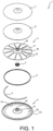
- FIG. 1 is an exploded perspective view of the electronic cymbal 1 in an embodiment.
- FIG. 2 is a cross-sectional view of the electronic cymbal 1.
- FIG. 2 shows a cross section taken along a plane along the axis of the electronic cymbal 1. Further, in FIG. 2 , hatching of a film member 7 is omitted in order to simplify the drawing.
- the electronic cymbal 1 is a disk-shaped electronic percussion instrument that simulates an acoustic cymbal.
- the electronic cymbal 1 is supported by a rod 2 (see FIG. 2 ) via a support rubber 3.
- the rod 2 includes a support 20 for restricting the downward of the electronic cymbal 1 (see the left enlarged part of FIG. 2 ).
- the support 20 is a cylindrical body that is tapered toward the upper end, and is attached to the rod 2 in a state in which downward displacement is restricted.
- the support rubber 3 is formed in a cylindrical shape having a through hole 30 in the center, and is configured such that the support rubber 3 is hooked to the support 20 by passing the rod 2 through the through hole 30 of the support rubber 3, and the electronic cymbal 1 is supported on the rod 2 in this way.
- a cylindrical felt washer 21 to the rod 2 to overlap the support rubber 3 in the supported state, by fastening a tightening nut 22 to the rod 2 while compressing the felt washer 21, the electronic cymbal 1 is supported in a swingable state with respect to the rod 2.
- a groove 31 extending in the circumferential direction is formed in the outer peripheral surface of the support rubber 3.
- a pair of grooves 31 are formed on the outer peripheral surface of the support rubber 3 at predetermined intervals in the vertical direction, and the inner edge parts of a bow frame 4 and an edge frame 5 are fitted into the pair of grooves 31 respectively.
- the bow frame 4 and the edge frame 5 are disk-shaped frames having through holes 40 and 50 in the center for fitting the support rubber 3 (groove 31).
- the bow frame 4 and the edge frame 5 are made of synthetic resin, fiber-reinforced resin, or the like.
- a bow sensor S1 and an edge sensor S2 are attached to the bow frame 4 and the edge frame 5.
- the bow sensor S1 and the edge sensor S2 are piezo pickups (piezoelectric elements), respectively.
- the bow sensor S1 detects the vibration when the bow frame 4 is hit
- the edge sensor S2 detects the vibration when the edge frame 5 is hit.
- Hits detected by the bow sensor S1 and the edge sensor S2 are converted into electrical signals and input to a sound source device (not shown).
- musical sounds corresponding to hits on the bow frame 4 and the edge frame 5 that is, bow sounds when the bow frame 4 is hit and edge sounds when the edge frame 5 is hit are generated.
- the bow frame 4 is a frame that configures substantially the entire upper surface (hit surface) of the electronic cymbal 1
- the edge frame 5 is a frame that configures the outer edge portion of the upper surface (hit surface) of the electronic cymbal 1.
- the bow frame 4 includes a bell portion 41 simulating the bell of an acoustic cymbal and a bow portion 42 simulating a bow.
- the bell portion 41 is formed in a bowl shape that is inclined downward radially outward from the center of the bow frame 4, and the bow portion 42 is formed in an annular shape that is inclined downward radially outward from the outer edge of the bell portion 41.
- the bow sensor S1 is attached to the lower surface of the bell portion 41. That is, since the bow sensor S1 is disposed closer to the center near the rod 2 than the outer edge of the bow frame 4, even if the bow frame 4 is hit at different positions in the circumferential direction, the length of the vibration propagation path from each hit position to the bow sensor S1 may be made uniform. Therefore, it is possible to make the hit sensitivity distribution uniform regardless of the difference in the hit position on the bow frame 4 in the circumferential direction.
- the edge frame 5 includes an inner peripheral portion 51 vertically facing the bell portion 41 of the bow frame 4 and an outer peripheral portion 52 vertically facing the bow portion 42 of the bow frame 4.
- the edge sensor S2 is attached to the lower surface of the inner peripheral portion 51. That is, the edge sensor S2 is disposed at a position overlapping the bell portion 41 of the bow frame 4 when viewed in the vertical direction, and closer to the center than the outer edge of the edge frame 5 and closer to the rod 2. Therefore, it is possible to make the hit sensitivity distribution uniform regardless of the difference in the hit position on the edge frame 5 in the circumferential direction.
- An inner peripheral portion 51 of the edge frame 5 is formed in a bowl shape that is inclined downward from the center side of the edge frame 5 toward the outside in the radial direction. That is, the inner peripheral portion 51 of the edge frame 5 is formed in the same shape as the bell portion 41 of the bow frame 4.
- the outer peripheral portion 52 of the edge frame 5 is formed in an annular shape that is inclined downward from the outer edge of the inner peripheral portion 51 toward the outside in the radial direction, and the outer peripheral portion 52 as a whole is formed substantially in the same shape as the bow portion 42 of the bow frame 4.
- the portion on the outer edge side of the outer peripheral portion 52 is slightly inclined upward to approach the outer edge of the bow portion 42 of the bow frame 4, and a bent portion 53 is bent upward from the outer edge of the upwardly inclined outer peripheral portion 52.
- an overhang portion 54 is overhanging in a flange shape toward the outer peripheral side (outside in the radial direction).
- the edge frame 5 is configured by forming the inner peripheral portion 51, the outer peripheral portion 52, the bent portion 53, and the overhang portion 54 as one piece.
- the overhang portion 54 forming the outer edge part of the edge frame 5 is located on the outer peripheral side (outside in the radial direction ) of the outer edge of the bow portion 42 of the bow frame 4, and the overhang portion 54 forms an edge portion of the upper surface of the electronic cymbal 1. Therefore, when the performer plays the electronic cymbal 1 by hitting the edge portion of the electronic cymbal 1, the overhang portion 54 is hit. Vibration when the overhang portion 54 is hit is detected by the edge sensor S2 attached to the edge frame 5.
- the overhang portion 54 (the edge portion of the electronic cymbal 1) has been hit by vibration detection by the edge sensor S2 instead of by pressure detection by a sheet sensor as in the conventional technology. It is thus possible to detect a hit with suitable precision even when the performer hits the overhang portion 54 from the side with a stick 100 (see FIG. 3 ) in an upright orientation or when the overhang portion 54 is hit lightly.
- each frame in a supported state in which the bow frame 4 and the edge frame 5 (hereinafter also referred to as "each frame") are supported by the rod 2 via the support rubber 3, each of the frames are in a non-contact state. Therefore, it is possible to prevent the bow sensor S 1 (edge sensor S2) attached to the bow frame 4 (edge frame 5) from erroneously detecting vibration when the edge frame 5 (bow frame 4) is hit.
- the vibration when each frame is hit may be damped by the support rubber 3. Therefore, when one of the frames is hit, the vibration may be suppressed from being propagated to the other frame via the support rubber 3; therefore, it is possible to accurately determine which of the bow frame 4 and the edge frame 5 (overhang portion 54) has been hit.
- an acoustic cymbal is made of metal and has a relatively small coefficient of friction, it is possible to hit the acoustic cymbal by sliding the stick on the upper surface of the acoustic cymbal. Therefore, in this embodiment, the upper surface and the outer peripheral surface of the overhang portion 54 of the edge frame 5 are not covered with a cover (cushioning material) such as rubber. As a result, it is possible to hit the overhang portion 54 by sliding the stick on the overhang portion 54; therefore, it is possible to impart a feeling of playing similar to that of an acoustic cymbal.
- the edge frame 5 When the overhang portion 54 of the edge frame 5 is not covered with a cushioning material as in this embodiment, it is preferable to form the edge frame 5 using a fiber reinforced resin (for example, glass fiber reinforced nylon). As a result, since the strength of the edge frame 5 may be ensured, damage to the edge frame 5 may be suppressed even if the overhang portion 54 is directly hit.
- a fiber reinforced resin for example, glass fiber reinforced nylon
- this embodiment adopts a configuration capable of addressing this issue. This configuration will be described below.
- the upper surface of the bow frame 4 is covered with a cover member 6 made of foamed resin (polyurethane foam in this embodiment).
- the cover member 6 has a through hole in the center and is formed in a disc shape having substantially the same shape as the bow frame 4, and is attached to the bow frame 4 to cover the upper surface of the bow frame 4 from the inner edge to the outer edge.
- the cover member 6 is made of foamed resin which is softer than rubber, the cover member 6 may absorb the impact of hitting with a stick or the like. Therefore, the hitting sound the time of hitting the bow frame 4 may be effectively reduced. In addition, since the cover member 6 made of foamed resin is easily damaged when directly hit, the upper surface of the cover member 6 is covered with the film member 7.
- the film member 7 is a plain weave fabric (mesh) formed using synthetic fibers (polyester in this embodiment).
- the film member 7 is formed in a disc shape having a through hole in the center, and covers the upper surface of the cover member 6 from the inner edge to the outer edge. Since the film member 7 formed using synthetic fibers has higher strength than the cover member 6 made of foamed resin, the film member 7 may protect the cover member 6 from hit.
- the film member 7 is a plain weave fabric made of synthetic fibers, it has a lower coefficient of friction than rubber. Therefore, since it is possible to hit the upper surface of the film member 7 by sliding the stick over it, it is possible to impart a feeling of playing close to that of an acoustic cymbal.
- the upper surface of the bow frame 4 made of resin is covered with the cover member 6 made of foamed resin, and the upper surface of the cover member 6 is covered with the film member 7 which is a woven fabric formed using synthetic fibers; in this way, it is possible to reduce the hitting sound the time of hitting and to provide the feeling of playing like that of an acoustic cymbal.
- the upper surface of the film member 7 and the upper surface of the overhang portion 54 of the edge frame 5 are configured to be flush with each other before hitting. As a result, even when the upper surface of the electronic cymbal 1 includes two frames, the bow frame 4 and the edge frame 5, the shape of the upper surface may be approximated to that of an acoustic cymbal.
- the bow frame 4 is formed with multiple slits 43 (see FIG. 1 ) penetrating vertically, and the slits 43 divide the bow frame 4 into multiple regions. As a result, the propagation of vibration when the bow frame 4 (film member 7) is hit is blocked by the slit 43, so that the entire bow frame 4 may be prevented from vibrating when the bow frame 4 is hit. Therefore, the hitting sound at the time of hitting the bow frame 4 may be reduced more effectively.
- the slit 43 is formed in the bow frame 4 as in this embodiment, it is preferable to form the bow frame 4 using a fiber reinforced resin (for example, glass fiber reinforced nylon). As a result, the rigidity of the bow frame 4 may be ensured even when the slit 43 penetrating vertically are formed.
- a fiber reinforced resin for example, glass fiber reinforced nylon
- the slit 43 when forming the slit 43 to suppress the vibration of the entire bow frame 4, it is possible to form the slit 43 in a curved shape extending in the circumferential direction, for example.
- the propagation of vibration toward the bow sensor S1 is likely to be blocked by the slit 43.
- multiple (12 in this embodiment) linear slits 43 extending in the radial direction are provided side by side in the bow portion 42 of the bow frame 4 at equal intervals in the circumferential direction. That is, the multiple slits 43 are formed radially around the bell portion 41 where the bow sensor S1 is disposed.
- a vibration propagation path extending in the radial direction may be formed between the multiple slits 43, so that vibration when the bow portion 42 of the bow frame 4 is hit may be easily propagated to the bow sensor S1. Therefore, compared with the case where the slit 43 is formed in a curved shape extending in the circumferential direction, the hit to the bow portion 42 may be detected with high accuracy.
- FIG. 3 is a cross-sectional view of the electronic cymbal 1 showing a state in which the overhang portion 54 of the edge frame 5 is hit from the state in FIG. 2 .
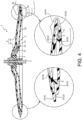
- FIG. 4 is a cross-sectional view of the electronic cymbal 1 showing a state in which choke is played.
- the inner edge parts of the bow frame 4 and the edge frame 5 are fitted in the support rubber 3 made of rubber. Therefore, when the overhang portion 54 of the edge frame 5 is hit by the stick 100 or the like, the edge frame 5 near the hit position is relatively displaced downward away from the bow frame 4 (see the enlarged part on the right side of FIG. 3 ). Due to this displacement of the edge frame 5, the edge frame 5 is relatively displaced to approach the bow frame 4 in the region opposite to the hit position with the rod 2 interposed therebetween.
- a cushioning material 8 is disposed between the bow frame 4 and the edge frame 5.
- the cushioning material 8 is formed in an annular shape that is continuous in the circumferential direction (see FIG. 1 ), and is disposed between the lower surface of the bow portion 42 of the bow frame 4 on the outer edge side and the outer peripheral portion 52 of the edge frame 5. In this way, the contact between each frame at the time of hitting may be restricted by the cushioning material 8. Since the cushioning material 8 is formed using a material having a predetermined elasticity (a material softer than each frame) such as sponge, rubber, or thermoplastic elastomer, when one of the frames is hit, it is possible to suppress propagation of vibration to the other frame by the cushioning material 8. Therefore, it is possible to accurately determine which of the frames has been hit.
- a material having a predetermined elasticity such as sponge, rubber, or thermoplastic elastomer
- the cushioning material 8 is formed in an annular shape that is continuous in the circumferential direction, and in a state before the bow frame 4 or the edge frame 5 is hit (hereinafter referred to as "state before hitting"), the bow frame 4 and the edge frame 5 (seat sensor 9 to be described later) are in contact with the cushioning material 8. That is, the space SP between the bow frame 4 and the edge frame 5 is closed by the cushioning material 8, and a (closed) space SP surrounded by the rod 2 (support rubber 3), the bow frame 4, the edge frame 5 and the cushioning material 8 is formed between the bow frame 4 and the edge frame 5.
- the cushioning material 8 is attached to the lower surface of the bow frame 4, and the thickness of the cushioning material 8 is formed thicker than the space between the lower surface of the bow frame 4 and the upper surface of the edge frame 5. Therefore, the cushioning material 8 is compressed by a predetermined amount between the bow frame 4 and the edge frame 5 in the state before hitting.
- the cushioning material 8 may follow the displacement of the bow frame 4 and the edge frame 5 away from each other, so that the space SP between the bow frame 4 and the edge frame 5 is kept closed by the cushioning material 8 (see the enlarged part on the right side of FIG. 3 ). Therefore, it is possible to suppress the vibration of the bow frame 4 (film member 7) from propagating through the space SP and being released to the outside; therefore, the hitting sound at the time of hitting the bow frame 4 may be reduced more effectively.
- the cushioning material 8 may be configured to be attached to each of the lower surface of the bow frame 4 and the upper surface of the edge frame 5 (seat sensor 9 to be described later). With this configuration, a state in which the space between the bow frame 4 and the edge frame 5 is closed by the cushioning material 8 may be reliably maintained.
- this embodiment adopts a configuration in which the compression of the cushioning material 8 is used to detect the choke playing.
- a seat sensor 9 is provided between the cushioning material 8 and the upper surface of the outer peripheral portion 52 of the edge frame 5.
- the seat sensor 9 is a strip-shaped membrane switch (pressure-sensitive sensor) that detects pressure changes.
- the seat sensor 9 is pinched between the cushioning material 8 and the outer peripheral portion 52 of the edge frame 5, and the pressure at the time of pinching is detected by the sheet sensor 9. Then, it is configured to attenuate (reduce or mute) the musical sound already generated by the hitting when the pressure detected by the seat sensor 9 reaches a predetermined pressure. This makes it possible to simulate choke playing in which the electronic cymbal 1 is hit and then muted.
- the seat sensor 9 may be pinched between each frame and the cushioning material 8. Therefore, compared with conventional electronic cymbals, the area in which the choke playing may be detected may be expanded in the radial direction; therefore, it is possible to accurately detect that the choke playing has been performed.
- the seat sensor 9 is attached substantially half the circumference of the edge frame 5 (see FIG. 1 ), and the cushioning material 8 that pushes the seat sensor 9 is formed in an annular shape that is continuous in the circumferential direction. That is, the cushioning material 8 is configured to continuously contact the seat sensor 9 from one end to the other end of the seat sensor 9 (the entire seat sensor 9) in the circumferential direction.
- the pressure when the cushioning material 8 is compressed may be reliably detected by the seat sensor 9, for example, compared with the case where the cushioning material 8 contacts the seat sensor 9 intermittently in the circumferential direction. Therefore, it is possible to more accurately detect that the choke playing has been performed.
- Such pinching of the seat sensor 9 by each frame and the cushioning material 8 may also occur when one of the bow frame 4 and the edge frame 5 is hit. Due to the pressure detected by the seat sensor 9 at the time of hitting, there is a possibility that it may be erroneously determined that the choke playing has been performed even though the player is performing the hitting.
- the choke playing has been performed when a predetermined pressure detected by the seat sensor 9 continues for a predetermined period of time (for example, 0.1 seconds). That is, the musical tone being generated is attenuated when the sheet sensor 9 detects that the bow frame 4 and the edge frame 5 are pinched (gripped) for a predetermined period of time or longer.
- a predetermined pressure detected by the seat sensor 9 continues for a predetermined period of time (for example, 0.1 seconds). That is, the musical tone being generated is attenuated when the sheet sensor 9 detects that the bow frame 4 and the edge frame 5 are pinched (gripped) for a predetermined period of time or longer.
- the electronic cymbal 1 was exemplified as an example of the electronic percussion instrument, but the disclosure is not limited thereto.
- the configurations of the above embodiments may be applied to electronic pads. Therefore, for example, the bow frame 4 (first frame) and edge frame 5 (second frame) may be formed in a rectangular or other polygonal shape. That is, the technical ideas of the above embodiment may be applied to any electronic musical instrument that generates different musical tones depending on the difference in hit positions between the upper surface and the outer edge part (edge portion) of the upper surface of the electronic percussion instrument.
- the bow frame 4 and the edge frame 5 are each supported by the rod 2 via one support rubber 3, but the disclosure is not limited thereto.
- the bow frame 4 and the edge frame 5 may be supported on the rod 2 by separate support rubbers, or the bow frame 4 and the edge frame 5 may be supported on the rod 2 by a member formed using a material other than rubber (for example, an elastic body such as an elastomer).
- the support rubber 3 made of rubber was exemplified as an example of the elastic body for supporting each frame on the rod 2, but the elastic body for supporting each frame on the rod 2 preferably uses a material that is at least softer than each frame. As a result, it is possible to suppress propagation of vibration to the other frame via the elastic body when one of the frames is hit.
- one of the frames is supported by the rod 2 via an elastic body, and the other frame is attached to the one frame via the cushioning material 8 (both upper and lower surfaces of the cushioning material 8 are attached to each frame with double-sided tape or the like). That is, it may be configured that the other frame is not in contact with the rod 2 by supporting only one of the frames on the rod 2 and supporting the other frame on the rod 2 via the one frame and the cushioning material 8.
- the piezo pickup was exemplified as an example of the bow sensor S1 and the edge sensor S2 that detect the vibration of the bow frame 4 and the edge frame 5, but the disclosure is not limited thereto.
- a known sensor such as a piezoelectric sensor, an electrodynamic sensor, or a capacitive sensor may be applied as long as it may detect the vibration of each frame.
- one bow sensor S 1 and one edge sensor S2 are attached near the center of the bow frame 4 and the edge frame 5, but the disclosure is not limited thereto.
- multiple bow sensors S 1 and edge sensors S2 may be provided, or may be disposed at a position closer to the outer edge side than the center of the bow frame 4 or the edge frame 5.
- the slits 43 are radially formed (the slits 43 are formed linearly along the radial direction) in the bow portion 42 of the bow frame 4, but the disclosure is not limited thereto.
- the slit 43 may be curved or linear extending in the circumferential direction, or may be a combination of curved lines and straight lines (for example, a wave shape or a zigzag shape).
- the slit 43 may be formed in the bell portion 41 of the bow frame 4, or the slit 43 may be omitted.
- the overhang portion 54 (edge portion) of the edge frame 5 was not covered with rubber (elastic body), but the disclosure is not limited thereto.
- the upper surface and the outer peripheral surface of the overhang portion 54 may be covered with an elastic body such as rubber (a material softer than the edge frame 5).
- an elastic body such as rubber (a material softer than the edge frame 5).
- the overhang portion 54 (edge frame 5) may be formed using a relatively soft material, for example, a material softer than the bow frame 4.
- the upper surface of the overhang portion 54 of the edge frame 5 is flush with the edge portion of the upper surface of the film member 7, but the disclosure is not limited thereto.
- the upper surface of the overhang portion 54 may be positioned above or below the edge portion of the upper surface of the film member 7.
- the cushioning material 8 is in contact with the bow frame 4 and the edge frame 5 (seat sensor 9) in the state before hitting, but the disclosure is not limited thereto.
- the thickness of the cushioning material 8 may be made thinner than the gap between the bow frame 4 and the edge frame 5 so that the cushioning material 8 does not come into contact with the bow frame 4 or the edge frame 5 in the state before hitting.
- the cushioning material 8 may be formed with a thickness that does not allow the frames to come into contact with each other at the time of hitting.
- the cushioning material 8 may be omitted.
- the cushioning material 8 is formed in an annular shape that is continuous in the circumferential direction, but the disclosure is not limited thereto.
- the cushioning material 8 may be intermittently formed in the circumferential direction. With this configuration, the vibration of hitting one of the bow frame 4 and the edge frame 5 is less likely to be propagated to the other frame via the cushioning material 8.
- the disclosure is not limited thereto.
- it may be configured that the upper surface of the bow frame 4 is covered with a rubber cover.
- the film member 7 may be simply placed on the cover member 6 (in a relatively displaceable state), or the film member 7 may be fixed (attached) to the cover member 6.
- the cover member 6 and the film member 7 may be omitted.
- the film member 7 is a plain weave fabric (mesh) formed using synthetic fibers, but the disclosure is not limited thereto.
- the film member 7 may be formed using a non-woven fabric using synthetic fibers or a resin film. That is, the film member 7 may be made of a material that has a higher strength against hit than the cover member 6 and has a slippery upper surface (lower coefficient of friction) than the cover member 6.
- the sheet sensor 9 is a membrane switch
- known sensors such as conductive rubber sensors, cable sensors, and capacitive touch sensors may be used as long as they may detect the pressure when each frame is pinched.
- a change in the gap between the frames is detected by a non-contact sensor (for example, a sensor that detects changes in magnetic field or capacitance, or an optical sensor).
- the sheet sensor 9 may be configured to detect that each frame is pinched by ON/OFF of the sensor. In this case, if the ON time of the sensor continues for a predetermined period of time, it may be determined that the choke playing has been performed (and the musical tones that have already been generated are attenuated). As a result, it is possible to prevent an erroneous determination that the sensor ON at the time of hitting is the choke playing.
- the seat sensor 9 is provided between the edge frame 5 and the cushioning material 8, but the disclosure is not limited thereto.
- the seat sensor 9 may be provided between the bow frame 4 and the cushioning material 8, or may be attached to the lower surface of the edge frame 5.
- the sheet sensor 9 may be omitted.
Landscapes
- Physics & Mathematics (AREA)
- Engineering & Computer Science (AREA)
- Acoustics & Sound (AREA)
- Multimedia (AREA)
- Electrophonic Musical Instruments (AREA)
Abstract
Description
- The disclosure relates to an electronic percussion instrument and a hit detection method, and more particularly to an electronic percussion instrument and hit detection method capable of improving hit detection accuracy.
- There is a technique for detecting a hit on the edge of an electronic cymbal. For example,
Patent Literature 1 describes an electronic cymbal in which asheet sensor 7 is pinched between an upper surface of an edge portion of aframe 3 and acover 2 covering the upper surface of theframe 3. According to this electronic cymbal, since thesheet sensor 7 detects the pressure when the edge portion of the frame 3 (cover 2) is hit, it is possible to determine whether the edge portion is hit or not based on the detected pressure. - [Patent Literature 1] Japanese Patent Laid-Open No.
Japanese Laid-Open No. 2002-207481 FIGs. 1 and2 ) - However, with the above-described conventional technique, when the performer hits the edge portion from the side with the stick in an upright orientation, or when the edge portion is hit lightly, the sheet sensor may not detect the pressure. Therefore, there is a problem that the hit on the edge portion cannot be detected with high accuracy.
- The disclosure has been made in view of the above, and provides an electronic percussion instrument and a hit detection method capable of improving the accuracy of hit detection. Solution to Problem
- To achieve the above, an electronic percussion instrument according to the disclosure includes: a first frame having an upper surface configured as a hit surface; a first sensor attached to the first frame for detecting vibration of a hit to the first frame; a second frame disposed below the first frame in a non-contact state with the first frame and having an outer edge that is located on an outer peripheral side of an outer edge of the first frame to form an edge portion; and a second sensor attached to the second frame for detecting vibration of a hit to the second frame.
- A hit detection method for an electronic percussion instrument according to the disclosure is provided. The electronic percussion instrument includes: a first frame having an upper surface configured as a hit surface; a first sensor attached to the first frame for detecting vibration of a hit to the first frame; a second frame disposed below the first frame in a non-contact state with the first frame and having an outer edge that is located on an outer peripheral side of an outer edge of the first frame to form an edge portion; and a second sensor attached to the second frame for detecting vibration of a hit to the second frame. The hit detection method includes: determining which of the first frame and the second frame has been hit based on a ratio or difference between output values of the first sensor and the second sensor.
-
-
FIG. 1 is an exploded perspective view of the electronic cymbal in an embodiment. -
FIG. 2 is a cross-sectional view of the electronic cymbal. -
FIG. 3 is a cross-sectional view of the electronic cymbal showing a state in which the overhang portion of the edge frame is hit from the state inFIG. 2 . -
FIG. 4 is a cross-sectional view of the electronic cymbal showing a state in which choke is played. - Hereinafter, exemplary embodiments will be described with reference to the accompanying drawings. First, a configuration of an
electronic cymbal 1 will be described with reference toFIGs. 1 and2 .FIG. 1 is an exploded perspective view of theelectronic cymbal 1 in an embodiment.FIG. 2 is a cross-sectional view of theelectronic cymbal 1.FIG. 2 shows a cross section taken along a plane along the axis of theelectronic cymbal 1. Further, inFIG. 2 , hatching of afilm member 7 is omitted in order to simplify the drawing. - As shown in
FIGs. 1 and2 , theelectronic cymbal 1 is a disk-shaped electronic percussion instrument that simulates an acoustic cymbal. Theelectronic cymbal 1 is supported by a rod 2 (seeFIG. 2 ) via asupport rubber 3. - The
rod 2 includes asupport 20 for restricting the downward of the electronic cymbal 1 (see the left enlarged part ofFIG. 2 ). Thesupport 20 is a cylindrical body that is tapered toward the upper end, and is attached to therod 2 in a state in which downward displacement is restricted. - The
support rubber 3 is formed in a cylindrical shape having a throughhole 30 in the center, and is configured such that thesupport rubber 3 is hooked to thesupport 20 by passing therod 2 through the throughhole 30 of thesupport rubber 3, and theelectronic cymbal 1 is supported on therod 2 in this way. After attaching acylindrical felt washer 21 to therod 2 to overlap thesupport rubber 3 in the supported state, by fastening a tighteningnut 22 to therod 2 while compressing thefelt washer 21, theelectronic cymbal 1 is supported in a swingable state with respect to therod 2. - A
groove 31 extending in the circumferential direction is formed in the outer peripheral surface of thesupport rubber 3. A pair ofgrooves 31 are formed on the outer peripheral surface of thesupport rubber 3 at predetermined intervals in the vertical direction, and the inner edge parts of abow frame 4 and anedge frame 5 are fitted into the pair ofgrooves 31 respectively. - The
bow frame 4 and theedge frame 5 are disk-shaped frames having throughholes bow frame 4 and theedge frame 5 are made of synthetic resin, fiber-reinforced resin, or the like. A bow sensor S1 and an edge sensor S2 are attached to thebow frame 4 and theedge frame 5. - The bow sensor S1 and the edge sensor S2 are piezo pickups (piezoelectric elements), respectively. The bow sensor S1 detects the vibration when the
bow frame 4 is hit, and the edge sensor S2 detects the vibration when theedge frame 5 is hit. Hits detected by the bow sensor S1 and the edge sensor S2 are converted into electrical signals and input to a sound source device (not shown). As a result, musical sounds corresponding to hits on thebow frame 4 and theedge frame 5, that is, bow sounds when thebow frame 4 is hit and edge sounds when theedge frame 5 is hit are generated. - The
bow frame 4 is a frame that configures substantially the entire upper surface (hit surface) of theelectronic cymbal 1, and theedge frame 5 is a frame that configures the outer edge portion of the upper surface (hit surface) of theelectronic cymbal 1. Thebow frame 4 includes abell portion 41 simulating the bell of an acoustic cymbal and abow portion 42 simulating a bow. - The
bell portion 41 is formed in a bowl shape that is inclined downward radially outward from the center of thebow frame 4, and thebow portion 42 is formed in an annular shape that is inclined downward radially outward from the outer edge of thebell portion 41. The bow sensor S1 is attached to the lower surface of thebell portion 41. That is, since the bow sensor S1 is disposed closer to the center near therod 2 than the outer edge of thebow frame 4, even if thebow frame 4 is hit at different positions in the circumferential direction, the length of the vibration propagation path from each hit position to the bow sensor S1 may be made uniform. Therefore, it is possible to make the hit sensitivity distribution uniform regardless of the difference in the hit position on thebow frame 4 in the circumferential direction. - The
edge frame 5 includes an innerperipheral portion 51 vertically facing thebell portion 41 of thebow frame 4 and an outerperipheral portion 52 vertically facing thebow portion 42 of thebow frame 4. The edge sensor S2 is attached to the lower surface of the innerperipheral portion 51. That is, the edge sensor S2 is disposed at a position overlapping thebell portion 41 of thebow frame 4 when viewed in the vertical direction, and closer to the center than the outer edge of theedge frame 5 and closer to therod 2. Therefore, it is possible to make the hit sensitivity distribution uniform regardless of the difference in the hit position on theedge frame 5 in the circumferential direction. - An inner
peripheral portion 51 of theedge frame 5 is formed in a bowl shape that is inclined downward from the center side of theedge frame 5 toward the outside in the radial direction. That is, the innerperipheral portion 51 of theedge frame 5 is formed in the same shape as thebell portion 41 of thebow frame 4. - The outer
peripheral portion 52 of theedge frame 5 is formed in an annular shape that is inclined downward from the outer edge of the innerperipheral portion 51 toward the outside in the radial direction, and the outerperipheral portion 52 as a whole is formed substantially in the same shape as thebow portion 42 of thebow frame 4. In addition, the portion on the outer edge side of the outerperipheral portion 52 is slightly inclined upward to approach the outer edge of thebow portion 42 of thebow frame 4, and abent portion 53 is bent upward from the outer edge of the upwardly inclined outerperipheral portion 52. - From the upper end side of the
bent portion 53, anoverhang portion 54 is overhanging in a flange shape toward the outer peripheral side (outside in the radial direction). Theedge frame 5 is configured by forming the innerperipheral portion 51, the outerperipheral portion 52, thebent portion 53, and theoverhang portion 54 as one piece. - The
overhang portion 54 forming the outer edge part of theedge frame 5 is located on the outer peripheral side (outside in the radial direction ) of the outer edge of thebow portion 42 of thebow frame 4, and theoverhang portion 54 forms an edge portion of the upper surface of theelectronic cymbal 1. Therefore, when the performer plays theelectronic cymbal 1 by hitting the edge portion of theelectronic cymbal 1, theoverhang portion 54 is hit. Vibration when theoverhang portion 54 is hit is detected by the edge sensor S2 attached to theedge frame 5. - In other words, it is possible to detect whether the overhang portion 54 (the edge portion of the electronic cymbal 1) has been hit by vibration detection by the edge sensor S2 instead of by pressure detection by a sheet sensor as in the conventional technology. It is thus possible to detect a hit with suitable precision even when the performer hits the
overhang portion 54 from the side with a stick 100 (seeFIG. 3 ) in an upright orientation or when theoverhang portion 54 is hit lightly. - In addition, in a supported state in which the
bow frame 4 and the edge frame 5 (hereinafter also referred to as "each frame") are supported by therod 2 via thesupport rubber 3, each of the frames are in a non-contact state. Therefore, it is possible to prevent the bow sensor S 1 (edge sensor S2) attached to the bow frame 4 (edge frame 5) from erroneously detecting vibration when the edge frame 5 (bow frame 4) is hit. - Therefore, based on the ratio or difference between the output values of the bow sensor S1 and the edge sensor S2, by determining that the frame with the larger output value of the sensor has been hit, it is possible to accurately determine which of the
bow frame 4 and the edge frame 5 (overhang portion 54) has been hit. - In addition, since the
bow frame 4 and theedge frame 5 are each supported by therod 2 via the rubber-likeelastic support rubber 3, the vibration when each frame is hit may be damped by thesupport rubber 3. Therefore, when one of the frames is hit, the vibration may be suppressed from being propagated to the other frame via thesupport rubber 3; therefore, it is possible to accurately determine which of thebow frame 4 and the edge frame 5 (overhang portion 54) has been hit. - Here, since an acoustic cymbal is made of metal and has a relatively small coefficient of friction, it is possible to hit the acoustic cymbal by sliding the stick on the upper surface of the acoustic cymbal. Therefore, in this embodiment, the upper surface and the outer peripheral surface of the
overhang portion 54 of theedge frame 5 are not covered with a cover (cushioning material) such as rubber. As a result, it is possible to hit theoverhang portion 54 by sliding the stick on theoverhang portion 54; therefore, it is possible to impart a feeling of playing similar to that of an acoustic cymbal. - When the
overhang portion 54 of theedge frame 5 is not covered with a cushioning material as in this embodiment, it is preferable to form theedge frame 5 using a fiber reinforced resin (for example, glass fiber reinforced nylon). As a result, since the strength of theedge frame 5 may be ensured, damage to theedge frame 5 may be suppressed even if theoverhang portion 54 is directly hit. - As described above, when an acoustic cymbal is played, it is possible to hit the acoustic cymbal by sliding the stick on the upper surface. In order to simulate such a feeling of hitting during playing, it is better not to cover the frame with a cushioning material such as rubber. However, in a structure in which the cover is simply removed from the frame of the conventional electronic cymbal (for example,
Japanese Patent Application Laid-Open No. 2002-207481 - That is, in the configuration of the conventional electronic cymbal, there is a problem that it is difficult to achieve both reduction of the hitting sound at the time of hitting and to obtain a feeling of playing (feeling of hitting) like an acoustic cymbal. In this regard, this embodiment adopts a configuration capable of addressing this issue. This configuration will be described below.
- The upper surface of the
bow frame 4 is covered with a cover member 6 made of foamed resin (polyurethane foam in this embodiment). The cover member 6 has a through hole in the center and is formed in a disc shape having substantially the same shape as thebow frame 4, and is attached to thebow frame 4 to cover the upper surface of thebow frame 4 from the inner edge to the outer edge. - Since the cover member 6 is made of foamed resin which is softer than rubber, the cover member 6 may absorb the impact of hitting with a stick or the like. Therefore, the hitting sound the time of hitting the
bow frame 4 may be effectively reduced. In addition, since the cover member 6 made of foamed resin is easily damaged when directly hit, the upper surface of the cover member 6 is covered with thefilm member 7. - The
film member 7 is a plain weave fabric (mesh) formed using synthetic fibers (polyester in this embodiment). Thefilm member 7 is formed in a disc shape having a through hole in the center, and covers the upper surface of the cover member 6 from the inner edge to the outer edge. Since thefilm member 7 formed using synthetic fibers has higher strength than the cover member 6 made of foamed resin, thefilm member 7 may protect the cover member 6 from hit. - Furthermore, since the
film member 7 is a plain weave fabric made of synthetic fibers, it has a lower coefficient of friction than rubber. Therefore, since it is possible to hit the upper surface of thefilm member 7 by sliding the stick over it, it is possible to impart a feeling of playing close to that of an acoustic cymbal. - That is, as in this embodiment, the upper surface of the
bow frame 4 made of resin is covered with the cover member 6 made of foamed resin, and the upper surface of the cover member 6 is covered with thefilm member 7 which is a woven fabric formed using synthetic fibers; in this way, it is possible to reduce the hitting sound the time of hitting and to provide the feeling of playing like that of an acoustic cymbal. - Further, the upper surface of the
film member 7 and the upper surface of theoverhang portion 54 of theedge frame 5 are configured to be flush with each other before hitting. As a result, even when the upper surface of theelectronic cymbal 1 includes two frames, thebow frame 4 and theedge frame 5, the shape of the upper surface may be approximated to that of an acoustic cymbal. - The
bow frame 4 is formed with multiple slits 43 (seeFIG. 1 ) penetrating vertically, and theslits 43 divide thebow frame 4 into multiple regions. As a result, the propagation of vibration when the bow frame 4 (film member 7) is hit is blocked by theslit 43, so that theentire bow frame 4 may be prevented from vibrating when thebow frame 4 is hit. Therefore, the hitting sound at the time of hitting thebow frame 4 may be reduced more effectively. - When the
slit 43 is formed in thebow frame 4 as in this embodiment, it is preferable to form thebow frame 4 using a fiber reinforced resin (for example, glass fiber reinforced nylon). As a result, the rigidity of thebow frame 4 may be ensured even when theslit 43 penetrating vertically are formed. - In this way, when forming the
slit 43 to suppress the vibration of theentire bow frame 4, it is possible to form theslit 43 in a curved shape extending in the circumferential direction, for example. However, with such a configuration, when thebow portion 42 of thebow frame 4 is hit, the propagation of vibration toward the bow sensor S1 is likely to be blocked by theslit 43. - In this regard, in this embodiment, multiple (12 in this embodiment)
linear slits 43 extending in the radial direction are provided side by side in thebow portion 42 of thebow frame 4 at equal intervals in the circumferential direction. That is, themultiple slits 43 are formed radially around thebell portion 41 where the bow sensor S1 is disposed. As a result, a vibration propagation path extending in the radial direction may be formed between themultiple slits 43, so that vibration when thebow portion 42 of thebow frame 4 is hit may be easily propagated to the bow sensor S1. Therefore, compared with the case where theslit 43 is formed in a curved shape extending in the circumferential direction, the hit to thebow portion 42 may be detected with high accuracy. - Next, the configuration of the
electronic cymbal 1 will be further described with reference toFIGs. 3 and4 .FIG. 3 is a cross-sectional view of theelectronic cymbal 1 showing a state in which theoverhang portion 54 of theedge frame 5 is hit from the state inFIG. 2 .FIG. 4 is a cross-sectional view of theelectronic cymbal 1 showing a state in which choke is played. - As shown in
FIG. 3 , the inner edge parts of thebow frame 4 and theedge frame 5 are fitted in thesupport rubber 3 made of rubber. Therefore, when theoverhang portion 54 of theedge frame 5 is hit by thestick 100 or the like, theedge frame 5 near the hit position is relatively displaced downward away from the bow frame 4 (see the enlarged part on the right side ofFIG. 3 ). Due to this displacement of theedge frame 5, theedge frame 5 is relatively displaced to approach thebow frame 4 in the region opposite to the hit position with therod 2 interposed therebetween. - Such relative displacement in which the frames approach each other also occurs when the
bow frame 4 is hit. If the frames come into contact with each other due to this relative displacement, the vibration caused by hitting one frame is likely to be propagated to the other frame. Therefore, in this embodiment, acushioning material 8 is disposed between thebow frame 4 and theedge frame 5. - The
cushioning material 8 is formed in an annular shape that is continuous in the circumferential direction (seeFIG. 1 ), and is disposed between the lower surface of thebow portion 42 of thebow frame 4 on the outer edge side and the outerperipheral portion 52 of theedge frame 5. In this way, the contact between each frame at the time of hitting may be restricted by thecushioning material 8. Since thecushioning material 8 is formed using a material having a predetermined elasticity (a material softer than each frame) such as sponge, rubber, or thermoplastic elastomer, when one of the frames is hit, it is possible to suppress propagation of vibration to the other frame by thecushioning material 8. Therefore, it is possible to accurately determine which of the frames has been hit. - In addition, the
cushioning material 8 is formed in an annular shape that is continuous in the circumferential direction, and in a state before thebow frame 4 or theedge frame 5 is hit (hereinafter referred to as "state before hitting"), thebow frame 4 and the edge frame 5 (seat sensor 9 to be described later) are in contact with thecushioning material 8. That is, the space SP between thebow frame 4 and theedge frame 5 is closed by thecushioning material 8, and a (closed) space SP surrounded by the rod 2 (support rubber 3), thebow frame 4, theedge frame 5 and thecushioning material 8 is formed between thebow frame 4 and theedge frame 5. - As a result, it is possible to prevent the vibration of the bow frame 4 (film member 7) from propagating through the space SP between the
bow frame 4 and theedge frame 5 and being released to the outside of theelectronic cymbal 1; therefore, the hitting sound at the time of hitting thebow frame 4 may be reduced more effectively. - The
cushioning material 8 is attached to the lower surface of thebow frame 4, and the thickness of thecushioning material 8 is formed thicker than the space between the lower surface of thebow frame 4 and the upper surface of theedge frame 5. Therefore, thecushioning material 8 is compressed by a predetermined amount between thebow frame 4 and theedge frame 5 in the state before hitting. - As a result, the
cushioning material 8 may follow the displacement of thebow frame 4 and theedge frame 5 away from each other, so that the space SP between thebow frame 4 and theedge frame 5 is kept closed by the cushioning material 8 (see the enlarged part on the right side ofFIG. 3 ). Therefore, it is possible to suppress the vibration of the bow frame 4 (film member 7) from propagating through the space SP and being released to the outside; therefore, the hitting sound at the time of hitting thebow frame 4 may be reduced more effectively. - When the space SP between the
bow frame 4 and theedge frame 5 is closed by thecushioning material 8, thecushioning material 8 may be configured to be attached to each of the lower surface of thebow frame 4 and the upper surface of the edge frame 5 (seat sensor 9 to be described later). With this configuration, a state in which the space between thebow frame 4 and theedge frame 5 is closed by thecushioning material 8 may be reliably maintained. - In this way, since the
cushioning material 8 is compressed by the relative displacement of thebow frame 4 or theedge frame 5, this embodiment adopts a configuration in which the compression of thecushioning material 8 is used to detect the choke playing. - Specifically, a
seat sensor 9 is provided between the cushioningmaterial 8 and the upper surface of the outerperipheral portion 52 of theedge frame 5. Theseat sensor 9 is a strip-shaped membrane switch (pressure-sensitive sensor) that detects pressure changes. - As shown in
FIG. 4 , when thebow portion 42 of thebow frame 4 and the outerperipheral portion 52 of theedge frame 5 are held by the player, theseat sensor 9 is pinched between the cushioningmaterial 8 and the outerperipheral portion 52 of theedge frame 5, and the pressure at the time of pinching is detected by thesheet sensor 9. Then, it is configured to attenuate (reduce or mute) the musical sound already generated by the hitting when the pressure detected by theseat sensor 9 reaches a predetermined pressure. This makes it possible to simulate choke playing in which theelectronic cymbal 1 is hit and then muted. - In this case, when the acoustic cymbal is gripped by the player at any position where the player may grip it, the player may perform the choke playing regardless of the gripping position. On the other hand, as in conventional electronic cymbals (for example,
Japanese Patent Laid-Open No. 2002-207481 - In this regard, by providing the
seat sensor 9 between theedge frame 5 and thecushioning material 8 as in this embodiment, even if thebow frame 4 and theedge frame 5 are gripped at a position displaced from theseat sensor 9 in the radial direction (for example, the inner side in the radial direction of the seat sensor 9), theseat sensor 9 may be pinched between each frame and thecushioning material 8. Therefore, compared with conventional electronic cymbals, the area in which the choke playing may be detected may be expanded in the radial direction; therefore, it is possible to accurately detect that the choke playing has been performed. - Further, the
seat sensor 9 is attached substantially half the circumference of the edge frame 5 (seeFIG. 1 ), and thecushioning material 8 that pushes theseat sensor 9 is formed in an annular shape that is continuous in the circumferential direction. That is, thecushioning material 8 is configured to continuously contact theseat sensor 9 from one end to the other end of the seat sensor 9 (the entire seat sensor 9) in the circumferential direction. As a result, the pressure when thecushioning material 8 is compressed may be reliably detected by theseat sensor 9, for example, compared with the case where thecushioning material 8 contacts theseat sensor 9 intermittently in the circumferential direction. Therefore, it is possible to more accurately detect that the choke playing has been performed. - Such pinching of the
seat sensor 9 by each frame and thecushioning material 8 may also occur when one of thebow frame 4 and theedge frame 5 is hit. Due to the pressure detected by theseat sensor 9 at the time of hitting, there is a possibility that it may be erroneously determined that the choke playing has been performed even though the player is performing the hitting. - In this regard, in this embodiment, it is determined that the choke playing has been performed when a predetermined pressure detected by the
seat sensor 9 continues for a predetermined period of time (for example, 0.1 seconds). That is, the musical tone being generated is attenuated when thesheet sensor 9 detects that thebow frame 4 and theedge frame 5 are pinched (gripped) for a predetermined period of time or longer. As a result, it is possible to suppress erroneous determination that the pressure detected by theseat sensor 9 at the time of hitting is the pressure due to the choke playing. - Although the disclosure has been described based on the above embodiments, the disclosure is not limited to the above embodiments, and it can be easily inferred that various modifications and improvements can be made without departing from the spirit of the disclosure.
- In the above embodiment, the
electronic cymbal 1 was exemplified as an example of the electronic percussion instrument, but the disclosure is not limited thereto. For example, the configurations of the above embodiments may be applied to electronic pads. Therefore, for example, the bow frame 4 (first frame) and edge frame 5 (second frame) may be formed in a rectangular or other polygonal shape. That is, the technical ideas of the above embodiment may be applied to any electronic musical instrument that generates different musical tones depending on the difference in hit positions between the upper surface and the outer edge part (edge portion) of the upper surface of the electronic percussion instrument. - In the above embodiment, the
bow frame 4 and theedge frame 5 are each supported by therod 2 via onesupport rubber 3, but the disclosure is not limited thereto. For example, thebow frame 4 and theedge frame 5 may be supported on therod 2 by separate support rubbers, or thebow frame 4 and theedge frame 5 may be supported on therod 2 by a member formed using a material other than rubber (for example, an elastic body such as an elastomer). - That is, in the above embodiment, the
support rubber 3 made of rubber was exemplified as an example of the elastic body for supporting each frame on therod 2, but the elastic body for supporting each frame on therod 2 preferably uses a material that is at least softer than each frame. As a result, it is possible to suppress propagation of vibration to the other frame via the elastic body when one of the frames is hit. - It may be configured that one of the frames is supported by the
rod 2 via an elastic body, and the other frame is attached to the one frame via the cushioning material 8 (both upper and lower surfaces of thecushioning material 8 are attached to each frame with double-sided tape or the like). That is, it may be configured that the other frame is not in contact with therod 2 by supporting only one of the frames on therod 2 and supporting the other frame on therod 2 via the one frame and thecushioning material 8. - In the above embodiment, the piezo pickup was exemplified as an example of the bow sensor S1 and the edge sensor S2 that detect the vibration of the
bow frame 4 and theedge frame 5, but the disclosure is not limited thereto. For example, a known sensor such as a piezoelectric sensor, an electrodynamic sensor, or a capacitive sensor may be applied as long as it may detect the vibration of each frame. - In the above embodiment, the case has been described in which one
bow sensor S 1 and one edge sensor S2 are attached near the center of thebow frame 4 and theedge frame 5, but the disclosure is not limited thereto. For example, multiplebow sensors S 1 and edge sensors S2 may be provided, or may be disposed at a position closer to the outer edge side than the center of thebow frame 4 or theedge frame 5. - In the above embodiment, the case has been described in which the
slits 43 are radially formed (theslits 43 are formed linearly along the radial direction) in thebow portion 42 of thebow frame 4, but the disclosure is not limited thereto. For example, theslit 43 may be curved or linear extending in the circumferential direction, or may be a combination of curved lines and straight lines (for example, a wave shape or a zigzag shape). Also, theslit 43 may be formed in thebell portion 41 of thebow frame 4, or theslit 43 may be omitted. - In the above embodiment, the case has been described in which the overhang portion 54 (edge portion) of the
edge frame 5 was not covered with rubber (elastic body), but the disclosure is not limited thereto. For example, the upper surface and the outer peripheral surface of theoverhang portion 54 may be covered with an elastic body such as rubber (a material softer than the edge frame 5). As a result, it is possible to reduce the hitting sound at the time of hitting theoverhang portion 54. Also, in order to reduce the sound of hitting theoverhang portion 54, the overhang portion 54 (edge frame 5) may be formed using a relatively soft material, for example, a material softer than thebow frame 4. - In the above embodiment, the upper surface of the
overhang portion 54 of theedge frame 5 is flush with the edge portion of the upper surface of thefilm member 7, but the disclosure is not limited thereto. For example, the upper surface of theoverhang portion 54 may be positioned above or below the edge portion of the upper surface of thefilm member 7. - In the above embodiment, the
cushioning material 8 is in contact with thebow frame 4 and the edge frame 5 (seat sensor 9) in the state before hitting, but the disclosure is not limited thereto. For example, the thickness of thecushioning material 8 may be made thinner than the gap between thebow frame 4 and theedge frame 5 so that thecushioning material 8 does not come into contact with thebow frame 4 or theedge frame 5 in the state before hitting. In the case of such a configuration, thecushioning material 8 may be formed with a thickness that does not allow the frames to come into contact with each other at the time of hitting. Alternatively, thecushioning material 8 may be omitted. - In the above embodiment, the case has been described in which the
cushioning material 8 is formed in an annular shape that is continuous in the circumferential direction, but the disclosure is not limited thereto. For example, thecushioning material 8 may be intermittently formed in the circumferential direction. With this configuration, the vibration of hitting one of thebow frame 4 and theedge frame 5 is less likely to be propagated to the other frame via thecushioning material 8. - In the above embodiment, the case has been described in which the upper surface of the
bow frame 4 is covered with the cover member 6 and the upper surface of the cover member 6 is covered with thefilm member 7, but the disclosure is not limited thereto. For example, it may be configured that the upper surface of thebow frame 4 is covered with a rubber cover. - In the above embodiment, a detailed description of the method of attaching the
film member 7 to the cover member 6 has been omitted; thefilm member 7 may be simply placed on the cover member 6 (in a relatively displaceable state), or thefilm member 7 may be fixed (attached) to the cover member 6. Alternatively, the cover member 6 and thefilm member 7 may be omitted. - In the above embodiment, the case has been described in which the
film member 7 is a plain weave fabric (mesh) formed using synthetic fibers, but the disclosure is not limited thereto. For example, thefilm member 7 may be formed using a non-woven fabric using synthetic fibers or a resin film. That is, thefilm member 7 may be made of a material that has a higher strength against hit than the cover member 6 and has a slippery upper surface (lower coefficient of friction) than the cover member 6. - In the above embodiment, the case has been described in which the
sheet sensor 9 is a membrane switch, but the disclosure is not limited thereto. For example, known sensors such as conductive rubber sensors, cable sensors, and capacitive touch sensors may be used as long as they may detect the pressure when each frame is pinched. In addition, instead of detecting the pinching of each frame by pressure, a change in the gap between the frames is detected by a non-contact sensor (for example, a sensor that detects changes in magnetic field or capacitance, or an optical sensor). - Further, instead of detecting the pressure change with the
sheet sensor 9, it may be configured to detect that each frame is pinched by ON/OFF of the sensor. In this case, if the ON time of the sensor continues for a predetermined period of time, it may be determined that the choke playing has been performed (and the musical tones that have already been generated are attenuated). As a result, it is possible to prevent an erroneous determination that the sensor ON at the time of hitting is the choke playing. - In the above embodiment, the case has been described in which the
seat sensor 9 is provided between theedge frame 5 and thecushioning material 8, but the disclosure is not limited thereto. For example, theseat sensor 9 may be provided between thebow frame 4 and thecushioning material 8, or may be attached to the lower surface of theedge frame 5. Alternatively, thesheet sensor 9 may be omitted. -
- 1: electronic percussion instrument
- 2: rod
- 3: support rubber (elastic body)
- 4: bow frame (first frame)
- 41: bell portion
- 42: bow portion
- 43: slit
- 5: edge frame (second frame)
- 6: cover member
- 7: film member
- 8: cushioning material
- 9: seat sensor (third sensor)
- 54: overhang portion (edge portion)
- S1: bow sensor (first sensor)
- S2: edge sensor (second sensor)
Claims (12)
- An electronic percussion instrument comprising:a first frame having an upper surface configured as a hit surface;a first sensor attached to the first frame for detecting vibration of a hit to the first frame;a second frame disposed below the first frame in a non-contact state with the first frame and having an outer edge that is located on an outer peripheral side of an outer edge of the first frame to form an edge portion; anda second sensor attached to the second frame for detecting vibration of a hit to the second frame.
- The electronic percussion instrument according to claim 1, further comprising an elastic body supported by a rod,
wherein the first frame and the second frame are supported by the rod via the elastic body. - The electronic percussion instrument according to claim 2, further comprising a cushioning material having a predetermined elasticity and provided between a lower surface of the outer edge side of the first frame and an upper surface of the second frame,
wherein contact between the first frame and the second frame is restricted by the cushioning material in response to the first frame or the second frame being hit. - The electronic percussion instrument according to claim 3, wherein the cushioning material is formed continuously in a circumferential direction centering on the rod, and
a space between the first frame and the second frame is closed by the cushioning material. - The electronic percussion instrument according to claim 3 or 4, further comprising a third sensor provided between the cushioning material and the first frame or the second frame,
wherein a musical tone being generated is attenuated in response to the third sensor detecting that the first frame and the second frame are pinched. - The electronic percussion instrument according to claim 5, wherein a musical tone being generated is attenuated in response to the third sensor detecting that the first frame and the second frame are pinched for a predetermined period of time or longer.
- The electronic percussion instrument according to any one of claims 1 to 6, wherein the first frame is configured as an electronic cymbal having a bell portion and a bow portion, and
the second sensor is disposed at a position overlapping with the bell portion when viewed in a vertical direction. - The electronic percussion instrument according to any one of claims 1 to 7, wherein an upper surface and an outer peripheral surface of the edge portion of the second frame are not covered with an elastic body.
- The electronic percussion instrument according to any one of claims 1 to 8, further comprising:a cover member made of foamed resin that covers the upper surface of the first frame; anda film member covering an upper surface of the cover member and having a higher strength than the cover member,wherein the film member is a woven fabric or non-woven fabric formed using synthetic fibers, or a resin film.
- The electronic percussion instrument according to claim 9, wherein the first frame includes a plurality of slits penetrating vertically.
- The electronic percussion instrument according to claim 10, wherein the first frame is configured as an electronic cymbal having a bell portion and a bow portion,the first sensor is attached to the bell portion, andthe slits are formed radially centering on the first sensor side.
- A hit detection method for an electronic percussion instrument, wherein the electronic percussion instrument comprises:a first frame having an upper surface configured as a hit surface;a first sensor attached to the first frame for detecting vibration of a hit to the first frame;a second frame disposed below the first frame in a non-contact state with the first frame and having an outer edge that is located on an outer peripheral side of an outer edge of the first frame to form an edge portion; anda second sensor attached to the second frame for detecting vibration of a hit to the second frame,wherein the hit detection method comprises:
determining which of the first frame and the second frame has been hit based on a ratio or difference between output values of the first sensor and the second sensor.
Applications Claiming Priority (1)
| Application Number | Priority Date | Filing Date | Title |
|---|---|---|---|
| PCT/JP2020/032216 WO2022044171A1 (en) | 2020-08-26 | 2020-08-26 | Electronic percussion instrument and hit detection method |
Publications (3)
| Publication Number | Publication Date |
|---|---|
| EP4207181A1 true EP4207181A1 (en) | 2023-07-05 |
| EP4207181A4 EP4207181A4 (en) | 2023-10-25 |
| EP4207181B1 EP4207181B1 (en) | 2025-02-12 |
Family
ID=80352902
Family Applications (1)
| Application Number | Title | Priority Date | Filing Date |
|---|---|---|---|
| EP20951425.6A Active EP4207181B1 (en) | 2020-08-26 | 2020-08-26 | Electronic percussion instrument and hit detection method |
Country Status (4)
| Country | Link |
|---|---|
| US (1) | US20230230567A1 (en) |
| EP (1) | EP4207181B1 (en) |
| CN (1) | CN115885341B (en) |
| WO (1) | WO2022044171A1 (en) |
Families Citing this family (4)
| Publication number | Priority date | Publication date | Assignee | Title |
|---|---|---|---|---|
| USD1042613S1 (en) * | 2021-12-21 | 2024-09-17 | Yuuki Emmeiji | Cymbal |
| EP4546331A4 (en) | 2022-06-23 | 2026-06-24 | Roland Corp | ELECTRONIC PERCENTRING INSTRUMENT AND METHOD FOR PRODUCING A NON-PERCENTRING SURFACE |
| JP2026126954A (en) * | 2025-01-24 | 2026-08-05 | ローランド株式会社 | Method for mounting electronic percussion instruments and sensors |
| JP2026126951A (en) * | 2025-01-24 | 2026-08-05 | ローランド株式会社 | Method for mounting electronic percussion instruments and sensors |
Family Cites Families (14)
| Publication number | Priority date | Publication date | Assignee | Title |
|---|---|---|---|---|
| JP3506340B2 (en) * | 1994-04-28 | 2004-03-15 | 株式会社コルグ | Electronic drum |
| JP3695035B2 (en) * | 1997-01-23 | 2005-09-14 | ヤマハ株式会社 | Electronic cymbals |
| US6632989B2 (en) * | 2000-08-22 | 2003-10-14 | Roland Corporation | Electronic pad with vibration isolation features |
| JP3754300B2 (en) | 2001-01-05 | 2006-03-08 | ローランド株式会社 | Electronic pad |
| JP4186845B2 (en) * | 2004-03-08 | 2008-11-26 | ヤマハ株式会社 | Electronic drum pad and electronic drum |
| US8946536B2 (en) * | 2010-11-16 | 2015-02-03 | Field Electronic Drums, Llc | Electronic cymbal assembly with modular self-dampening triggering system |
| TWM461858U (en) * | 2013-03-15 | 2013-09-11 | jun-wei Li | Electronic cymbal |
| JP2014203037A (en) * | 2013-04-09 | 2014-10-27 | ローランド株式会社 | Electronic cymbal |
| JP2015121728A (en) * | 2013-12-25 | 2015-07-02 | ローランド株式会社 | Electronic cymbal |
| JP2016024238A (en) * | 2014-07-16 | 2016-02-08 | ローランド株式会社 | Electronic pad |
| CN207124030U (en) * | 2016-01-13 | 2018-03-20 | 罗兰株式会社 | Electronic cymbal |
| JP2019113787A (en) * | 2017-12-26 | 2019-07-11 | ローランド株式会社 | Sound-damping tool for cymbal |
| JP2019117309A (en) * | 2017-12-27 | 2019-07-18 | ローランド株式会社 | Sound attenuator for cymbal |
| JP7199662B2 (en) * | 2019-05-09 | 2023-01-06 | 株式会社エフノート | electronic hi hat |
-
2020
- 2020-08-26 WO PCT/JP2020/032216 patent/WO2022044171A1/en not_active Ceased
- 2020-08-26 CN CN202080103464.9A patent/CN115885341B/en active Active
- 2020-08-26 EP EP20951425.6A patent/EP4207181B1/en active Active
- 2020-08-26 US US18/022,743 patent/US20230230567A1/en active Pending
Also Published As
| Publication number | Publication date |
|---|---|
| EP4207181B1 (en) | 2025-02-12 |
| CN115885341B (en) | 2025-05-13 |
| EP4207181A4 (en) | 2023-10-25 |
| WO2022044171A1 (en) | 2022-03-03 |
| US20230230567A1 (en) | 2023-07-20 |
| CN115885341A (en) | 2023-03-31 |
Similar Documents
| Publication | Publication Date | Title |
|---|---|---|
| EP4207181B1 (en) | Electronic percussion instrument and hit detection method | |
| US6881885B2 (en) | Electronic pad with vibration isolation features | |
| US6525249B1 (en) | Drumhead and muting structure for acoustic and electronic percussion instruments | |
| EP3531414B1 (en) | Electronic percussion instrument | |
| JPH043357Y2 (en) | ||
| EP3346461B1 (en) | Bass drum damper and bass drum | |
| US10467996B2 (en) | Cymbal damping tool and method of producing the same | |
| JP2018518698A (en) | Electronic system for generating electronic sounds that can be combined with wind instruments and musical instruments including such systems | |
| US11875765B2 (en) | Electronic percussion instrument and hitting detection method | |
| US5056403A (en) | Electronic drum with vibration isolating head | |
| JP5163070B2 (en) | Electronic percussion instrument | |
| JP3754300B2 (en) | Electronic pad | |
| US20250046283A1 (en) | Electronic percussion instrument, hit detection method and manufacturing method of electronic percussion instrument | |
| JP6210424B1 (en) | Electronic cymbal | |
| JP2005274727A (en) | Pad for percussion instrument | |
| JPH06175651A (en) | Electronic drum | |
| EP3843082B1 (en) | Drum head and attachment method of cushion | |
| JP3717169B2 (en) | Electronic pad | |
| US20250131901A1 (en) | Percussion instrument and method for reducing volume of percussion instrument | |
| JP7120299B2 (en) | Detection device and detection method | |
| JPH04135788U (en) | electronic percussion instruments | |
| GB2285848A (en) | Slide valve spring damping |
Legal Events
| Date | Code | Title | Description |
|---|---|---|---|
| STAA | Information on the status of an ep patent application or granted ep patent |
Free format text: STATUS: THE INTERNATIONAL PUBLICATION HAS BEEN MADE |
|
| PUAI | Public reference made under article 153(3) epc to a published international application that has entered the european phase |
Free format text: ORIGINAL CODE: 0009012 |
|
| STAA | Information on the status of an ep patent application or granted ep patent |
Free format text: STATUS: REQUEST FOR EXAMINATION WAS MADE |
|
| 17P | Request for examination filed |
Effective date: 20230222 |
|
| AK | Designated contracting states |
Kind code of ref document: A1 Designated state(s): AL AT BE BG CH CY CZ DE DK EE ES FI FR GB GR HR HU IE IS IT LI LT LU LV MC MK MT NL NO PL PT RO RS SE SI SK SM TR |
|
| A4 | Supplementary search report drawn up and despatched |
Effective date: 20230926 |
|
| RIC1 | Information provided on ipc code assigned before grant |
Ipc: G10H 3/14 20060101ALI20230920BHEP Ipc: G10H 1/32 20060101ALI20230920BHEP Ipc: G10H 1/34 20060101ALI20230920BHEP Ipc: G10H 1/00 20060101AFI20230920BHEP |
|
| DAV | Request for validation of the european patent (deleted) | ||
| DAX | Request for extension of the european patent (deleted) | ||
| STAA | Information on the status of an ep patent application or granted ep patent |
Free format text: STATUS: EXAMINATION IS IN PROGRESS |
|
| 17Q | First examination report despatched |
Effective date: 20240419 |
|
| GRAP | Despatch of communication of intention to grant a patent |
Free format text: ORIGINAL CODE: EPIDOSNIGR1 |
|
| STAA | Information on the status of an ep patent application or granted ep patent |
Free format text: STATUS: GRANT OF PATENT IS INTENDED |
|
| INTG | Intention to grant announced |
Effective date: 20241008 |
|
| P01 | Opt-out of the competence of the unified patent court (upc) registered |
Free format text: CASE NUMBER: APP_61520/2024 Effective date: 20241118 |
|
| GRAS | Grant fee paid |
Free format text: ORIGINAL CODE: EPIDOSNIGR3 |
|
| GRAA | (expected) grant |
Free format text: ORIGINAL CODE: 0009210 |
|
| STAA | Information on the status of an ep patent application or granted ep patent |
Free format text: STATUS: THE PATENT HAS BEEN GRANTED |
|
| AK | Designated contracting states |
Kind code of ref document: B1 Designated state(s): AL AT BE BG CH CY CZ DE DK EE ES FI FR GB GR HR HU IE IS IT LI LT LU LV MC MK MT NL NO PL PT RO RS SE SI SK SM TR |
|
| REG | Reference to a national code |
Ref country code: GB Ref legal event code: FG4D |
|
| REG | Reference to a national code |
Ref country code: CH Ref legal event code: EP |
|
| REG | Reference to a national code |
Ref country code: DE Ref legal event code: R096 Ref document number: 602020046165 Country of ref document: DE |
|
| REG | Reference to a national code |
Ref country code: IE Ref legal event code: FG4D |
|
| REG | Reference to a national code |
Ref country code: NL Ref legal event code: MP Effective date: 20250212 |
|
| PG25 | Lapsed in a contracting state [announced via postgrant information from national office to epo] |
Ref country code: RS Free format text: LAPSE BECAUSE OF FAILURE TO SUBMIT A TRANSLATION OF THE DESCRIPTION OR TO PAY THE FEE WITHIN THE PRESCRIBED TIME-LIMIT Effective date: 20250512 |
|
| PG25 | Lapsed in a contracting state [announced via postgrant information from national office to epo] |
Ref country code: FI Free format text: LAPSE BECAUSE OF FAILURE TO SUBMIT A TRANSLATION OF THE DESCRIPTION OR TO PAY THE FEE WITHIN THE PRESCRIBED TIME-LIMIT Effective date: 20250212 |
|
| PG25 | Lapsed in a contracting state [announced via postgrant information from national office to epo] |
Ref country code: PL Free format text: LAPSE BECAUSE OF FAILURE TO SUBMIT A TRANSLATION OF THE DESCRIPTION OR TO PAY THE FEE WITHIN THE PRESCRIBED TIME-LIMIT Effective date: 20250212 |
|
| PG25 | Lapsed in a contracting state [announced via postgrant information from national office to epo] |
Ref country code: ES Free format text: LAPSE BECAUSE OF FAILURE TO SUBMIT A TRANSLATION OF THE DESCRIPTION OR TO PAY THE FEE WITHIN THE PRESCRIBED TIME-LIMIT Effective date: 20250212 |
|
| REG | Reference to a national code |
Ref country code: LT Ref legal event code: MG9D |
|
| PG25 | Lapsed in a contracting state [announced via postgrant information from national office to epo] |
Ref country code: IS Free format text: LAPSE BECAUSE OF FAILURE TO SUBMIT A TRANSLATION OF THE DESCRIPTION OR TO PAY THE FEE WITHIN THE PRESCRIBED TIME-LIMIT Effective date: 20250612 Ref country code: NO Free format text: LAPSE BECAUSE OF FAILURE TO SUBMIT A TRANSLATION OF THE DESCRIPTION OR TO PAY THE FEE WITHIN THE PRESCRIBED TIME-LIMIT Effective date: 20250512 |
|
| PG25 | Lapsed in a contracting state [announced via postgrant information from national office to epo] |
Ref country code: NL Free format text: LAPSE BECAUSE OF FAILURE TO SUBMIT A TRANSLATION OF THE DESCRIPTION OR TO PAY THE FEE WITHIN THE PRESCRIBED TIME-LIMIT Effective date: 20250212 |
|
| PG25 | Lapsed in a contracting state [announced via postgrant information from national office to epo] |
Ref country code: HR Free format text: LAPSE BECAUSE OF FAILURE TO SUBMIT A TRANSLATION OF THE DESCRIPTION OR TO PAY THE FEE WITHIN THE PRESCRIBED TIME-LIMIT Effective date: 20250212 |
|
| PG25 | Lapsed in a contracting state [announced via postgrant information from national office to epo] |
Ref country code: PT Free format text: LAPSE BECAUSE OF FAILURE TO SUBMIT A TRANSLATION OF THE DESCRIPTION OR TO PAY THE FEE WITHIN THE PRESCRIBED TIME-LIMIT Effective date: 20250612 Ref country code: LV Free format text: LAPSE BECAUSE OF FAILURE TO SUBMIT A TRANSLATION OF THE DESCRIPTION OR TO PAY THE FEE WITHIN THE PRESCRIBED TIME-LIMIT Effective date: 20250212 |
|
| PG25 | Lapsed in a contracting state [announced via postgrant information from national office to epo] |
Ref country code: BG Free format text: LAPSE BECAUSE OF FAILURE TO SUBMIT A TRANSLATION OF THE DESCRIPTION OR TO PAY THE FEE WITHIN THE PRESCRIBED TIME-LIMIT Effective date: 20250212 Ref country code: GR Free format text: LAPSE BECAUSE OF FAILURE TO SUBMIT A TRANSLATION OF THE DESCRIPTION OR TO PAY THE FEE WITHIN THE PRESCRIBED TIME-LIMIT Effective date: 20250513 |
|
| REG | Reference to a national code |
Ref country code: AT Ref legal event code: MK05 Ref document number: 1766862 Country of ref document: AT Kind code of ref document: T Effective date: 20250212 |
|
| PG25 | Lapsed in a contracting state [announced via postgrant information from national office to epo] |
Ref country code: SE Free format text: LAPSE BECAUSE OF FAILURE TO SUBMIT A TRANSLATION OF THE DESCRIPTION OR TO PAY THE FEE WITHIN THE PRESCRIBED TIME-LIMIT Effective date: 20250212 |
|
| PG25 | Lapsed in a contracting state [announced via postgrant information from national office to epo] |
Ref country code: SM Free format text: LAPSE BECAUSE OF FAILURE TO SUBMIT A TRANSLATION OF THE DESCRIPTION OR TO PAY THE FEE WITHIN THE PRESCRIBED TIME-LIMIT Effective date: 20250212 |
|
| PG25 | Lapsed in a contracting state [announced via postgrant information from national office to epo] |
Ref country code: DK Free format text: LAPSE BECAUSE OF FAILURE TO SUBMIT A TRANSLATION OF THE DESCRIPTION OR TO PAY THE FEE WITHIN THE PRESCRIBED TIME-LIMIT Effective date: 20250212 |
|
| PGFP | Annual fee paid to national office [announced via postgrant information from national office to epo] |
Ref country code: DE Payment date: 20250702 Year of fee payment: 6 |
|
| PG25 | Lapsed in a contracting state [announced via postgrant information from national office to epo] |
Ref country code: IT Free format text: LAPSE BECAUSE OF FAILURE TO SUBMIT A TRANSLATION OF THE DESCRIPTION OR TO PAY THE FEE WITHIN THE PRESCRIBED TIME-LIMIT Effective date: 20250212 |
|
| PGFP | Annual fee paid to national office [announced via postgrant information from national office to epo] |
Ref country code: GB Payment date: 20250703 Year of fee payment: 6 |
|
| PG25 | Lapsed in a contracting state [announced via postgrant information from national office to epo] |
Ref country code: AT Free format text: LAPSE BECAUSE OF FAILURE TO SUBMIT A TRANSLATION OF THE DESCRIPTION OR TO PAY THE FEE WITHIN THE PRESCRIBED TIME-LIMIT Effective date: 20250212 |
|
| PGFP | Annual fee paid to national office [announced via postgrant information from national office to epo] |
Ref country code: FR Payment date: 20250703 Year of fee payment: 6 |
|
| PG25 | Lapsed in a contracting state [announced via postgrant information from national office to epo] |
Ref country code: EE Free format text: LAPSE BECAUSE OF FAILURE TO SUBMIT A TRANSLATION OF THE DESCRIPTION OR TO PAY THE FEE WITHIN THE PRESCRIBED TIME-LIMIT Effective date: 20250212 Ref country code: CZ Free format text: LAPSE BECAUSE OF FAILURE TO SUBMIT A TRANSLATION OF THE DESCRIPTION OR TO PAY THE FEE WITHIN THE PRESCRIBED TIME-LIMIT Effective date: 20250212 |
|
| PG25 | Lapsed in a contracting state [announced via postgrant information from national office to epo] |
Ref country code: RO Free format text: LAPSE BECAUSE OF FAILURE TO SUBMIT A TRANSLATION OF THE DESCRIPTION OR TO PAY THE FEE WITHIN THE PRESCRIBED TIME-LIMIT Effective date: 20250212 |
|
| PG25 | Lapsed in a contracting state [announced via postgrant information from national office to epo] |
Ref country code: SK Free format text: LAPSE BECAUSE OF FAILURE TO SUBMIT A TRANSLATION OF THE DESCRIPTION OR TO PAY THE FEE WITHIN THE PRESCRIBED TIME-LIMIT Effective date: 20250212 |
|
| REG | Reference to a national code |
Ref country code: DE Ref legal event code: R097 Ref document number: 602020046165 Country of ref document: DE |
|
| PLBE | No opposition filed within time limit |
Free format text: ORIGINAL CODE: 0009261 |
|
| STAA | Information on the status of an ep patent application or granted ep patent |
Free format text: STATUS: NO OPPOSITION FILED WITHIN TIME LIMIT |
|
| REG | Reference to a national code |
Ref country code: CH Ref legal event code: L10 Free format text: ST27 STATUS EVENT CODE: U-0-0-L10-L00 (AS PROVIDED BY THE NATIONAL OFFICE) Effective date: 20251224 |
|
| 26N | No opposition filed |
Effective date: 20251113 |
|
| REG | Reference to a national code |
Ref country code: CH Ref legal event code: H13 Free format text: ST27 STATUS EVENT CODE: U-0-0-H10-H13 (AS PROVIDED BY THE NATIONAL OFFICE) Effective date: 20260324 |
|
| PG25 | Lapsed in a contracting state [announced via postgrant information from national office to epo] |
Ref country code: MC Free format text: LAPSE BECAUSE OF FAILURE TO SUBMIT A TRANSLATION OF THE DESCRIPTION OR TO PAY THE FEE WITHIN THE PRESCRIBED TIME-LIMIT Effective date: 20250212 |
|
| PG25 | Lapsed in a contracting state [announced via postgrant information from national office to epo] |
Ref country code: LU Free format text: LAPSE BECAUSE OF NON-PAYMENT OF DUE FEES Effective date: 20250826 |
|
| PG25 | Lapsed in a contracting state [announced via postgrant information from national office to epo] |
Ref country code: CH Free format text: LAPSE BECAUSE OF NON-PAYMENT OF DUE FEES Effective date: 20250831 |
|
| REG | Reference to a national code |
Ref country code: BE Ref legal event code: MM Effective date: 20250831 |
|
| PG25 | Lapsed in a contracting state [announced via postgrant information from national office to epo] |
Ref country code: LT Free format text: LAPSE BECAUSE OF FAILURE TO SUBMIT A TRANSLATION OF THE DESCRIPTION OR TO PAY THE FEE WITHIN THE PRESCRIBED TIME-LIMIT Effective date: 20250212 |
|
| PG25 | Lapsed in a contracting state [announced via postgrant information from national office to epo] |
Ref country code: IE Free format text: LAPSE BECAUSE OF NON-PAYMENT OF DUE FEES Effective date: 20250826 Ref country code: BE Free format text: LAPSE BECAUSE OF NON-PAYMENT OF DUE FEES Effective date: 20250831 |