EP4206873A2 - Ensemble de support réglable pour un utilisateur de souris ergonomique, et souris d'ordinateur ergonomique réglable - Google Patents
Ensemble de support réglable pour un utilisateur de souris ergonomique, et souris d'ordinateur ergonomique réglable Download PDFInfo
- Publication number
- EP4206873A2 EP4206873A2 EP22216484.0A EP22216484A EP4206873A2 EP 4206873 A2 EP4206873 A2 EP 4206873A2 EP 22216484 A EP22216484 A EP 22216484A EP 4206873 A2 EP4206873 A2 EP 4206873A2
- Authority
- EP
- European Patent Office
- Prior art keywords
- adjustment member
- finger
- height adjustment
- mouse
- supporting assembly
- Prior art date
- Legal status (The legal status is an assumption and is not a legal conclusion. Google has not performed a legal analysis and makes no representation as to the accuracy of the status listed.)
- Pending
Links
- 230000008878 coupling Effects 0.000 claims description 5
- 238000010168 coupling process Methods 0.000 claims description 5
- 238000005859 coupling reaction Methods 0.000 claims description 5
- 239000013013 elastic material Substances 0.000 claims description 4
- 210000003811 finger Anatomy 0.000 description 66
- 230000033001 locomotion Effects 0.000 description 7
- 239000000463 material Substances 0.000 description 6
- 210000000707 wrist Anatomy 0.000 description 6
- 210000003205 muscle Anatomy 0.000 description 5
- 208000012514 Cumulative Trauma disease Diseases 0.000 description 4
- 238000006467 substitution reaction Methods 0.000 description 4
- 239000006260 foam Substances 0.000 description 3
- 230000009471 action Effects 0.000 description 2
- 230000001684 chronic effect Effects 0.000 description 2
- 230000006378 damage Effects 0.000 description 2
- 239000004744 fabric Substances 0.000 description 2
- 210000000245 forearm Anatomy 0.000 description 2
- 230000004048 modification Effects 0.000 description 2
- 238000012986 modification Methods 0.000 description 2
- 230000007935 neutral effect Effects 0.000 description 2
- 230000002093 peripheral effect Effects 0.000 description 2
- 210000002435 tendon Anatomy 0.000 description 2
- 235000001674 Agaricus brunnescens Nutrition 0.000 description 1
- 206010061218 Inflammation Diseases 0.000 description 1
- -1 but not limiting to Substances 0.000 description 1
- 239000012141 concentrate Substances 0.000 description 1
- 230000003247 decreasing effect Effects 0.000 description 1
- 238000005516 engineering process Methods 0.000 description 1
- 239000003292 glue Substances 0.000 description 1
- 210000004247 hand Anatomy 0.000 description 1
- 230000004054 inflammatory process Effects 0.000 description 1
- 210000003041 ligament Anatomy 0.000 description 1
- 230000007246 mechanism Effects 0.000 description 1
- 108700039855 mouse a Proteins 0.000 description 1
- 210000005036 nerve Anatomy 0.000 description 1
- 239000004033 plastic Substances 0.000 description 1
- 210000003813 thumb Anatomy 0.000 description 1
Images


Classifications
-
- G—PHYSICS
- G06—COMPUTING; CALCULATING OR COUNTING
- G06F—ELECTRIC DIGITAL DATA PROCESSING
- G06F3/00—Input arrangements for transferring data to be processed into a form capable of being handled by the computer; Output arrangements for transferring data from processing unit to output unit, e.g. interface arrangements
- G06F3/01—Input arrangements or combined input and output arrangements for interaction between user and computer
- G06F3/03—Arrangements for converting the position or the displacement of a member into a coded form
- G06F3/033—Pointing devices displaced or positioned by the user, e.g. mice, trackballs, pens or joysticks; Accessories therefor
- G06F3/0354—Pointing devices displaced or positioned by the user, e.g. mice, trackballs, pens or joysticks; Accessories therefor with detection of 2D relative movements between the device, or an operating part thereof, and a plane or surface, e.g. 2D mice, trackballs, pens or pucks
- G06F3/03543—Mice or pucks
-
- G—PHYSICS
- G06—COMPUTING; CALCULATING OR COUNTING
- G06F—ELECTRIC DIGITAL DATA PROCESSING
- G06F3/00—Input arrangements for transferring data to be processed into a form capable of being handled by the computer; Output arrangements for transferring data from processing unit to output unit, e.g. interface arrangements
- G06F3/01—Input arrangements or combined input and output arrangements for interaction between user and computer
- G06F3/03—Arrangements for converting the position or the displacement of a member into a coded form
- G06F3/033—Pointing devices displaced or positioned by the user, e.g. mice, trackballs, pens or joysticks; Accessories therefor
- G06F3/0354—Pointing devices displaced or positioned by the user, e.g. mice, trackballs, pens or joysticks; Accessories therefor with detection of 2D relative movements between the device, or an operating part thereof, and a plane or surface, e.g. 2D mice, trackballs, pens or pucks
-
- G—PHYSICS
- G06—COMPUTING; CALCULATING OR COUNTING
- G06F—ELECTRIC DIGITAL DATA PROCESSING
- G06F2203/00—Indexing scheme relating to G06F3/00 - G06F3/048
- G06F2203/033—Indexing scheme relating to G06F3/033
- G06F2203/0333—Ergonomic shaped mouse for one hand
Definitions
- the present invention relates generally to computer peripherals, and, more specifically, to an adjustable supporting assembly for user of an ergonomic mouse, and ergonomic adjustable computer mouse adapted for palm size placement, movement and finger operation.
- a computer mouse is typically used to control the movement and functions of the cursor on a computer by sliding it along a desktop and pressing buttons. Moreover, the computer mouse may figure out how much and in which direction hand or finger may be moved for required movement. Due to the convenience of its use, the mouse is nearly three times as popular as the keyboard among modern computer users. However, long duration of uses of the mouse has also highlighted one or more chronic problems associated with the tendons, nerves, and muscles particularly (But not limited to) in the back of the hand (Fingers and back of palm), wrist (Carpal area) forearm, arm, shoulder and neck, as the computer mouse requires the user to lay his or her palm on top of it while simultaneously constantly hovering the fingers without inadvertently touching the buttons to operate it.
- mice This often results in a variety of discomfort and fatigue difficulties, particularly in the user's hand and wrist.
- an extended use of such mouse may induce cumulative trauma disorder (CTD) or repetitive strain injuries (RSI).
- CTD cumulative trauma disorder
- RSI repetitive strain injuries
- wrist motions such as flexion and hyperextension
- flexion and hyperextension are also common among mouse users, resulting in inflammation in the hands and wrists.
- excessive arm and shoulder motions accompanied with the use of mouse may also cause soreness and fatigue in the arm, shoulders and neck of computer users.
- Typical support devices include stationary or moveable apparatus that support the hand, wrist, or palm.
- the invention replaces the standard computer mouse for any transitional personal computers that require both a keyboard and a computer mouse for input tasks.
- the substitution is ergonomically justified.
- the general purpose of the present disclosure is to provide an adjustable supporting assembly for user of an ergonomic mouse, and ergonomic adjustable computer mouse, to include all advantages of the prior art, and to overcome the drawbacks inherent in the prior art.
- An object of the present invention is to provide an adjustable supporting assembly for user of an ergonomic mouse a pre-designed hand base that makes it more comfortable for the user's hand. Further, object of the present invention discloser is to provide an adjustable supporting assembly for user of an ergonomic mouse, and ergonomic adjustable computer mouse that may improve the position in which a computer mouse is held or moved in a manner.
- Embodiments in accordance with the present invention disclose an adjustable supporting assembly for a user of a conventional mouse.
- the adjustable supporting assembly comprising at least one height adjustment member adapted to be coupled on a body of the conventional mouse for palm comfort.
- the adjustable supporting assembly comprising at least one finger adjustment member protruding laterally from the at least one height adjustment member for finger support.
- the at least one height adjustment member comprises: a base plate adapted to be coupled to a body of the conventional mouse; a dome shaped member adjustably coupled to the base plate, at least one screw member extents from the base plate and ends at the dome shaped member, wherein the at least one screw member is rotated to adjust a height of the dome shaped member on the base plate.
- the height adjustment member comprises slots in which the finger adjustment members are inserted to protrude laterally from the height adjustment member for supporting fingers of the user, and at least one another screw member extents from the base plate to an interior of the dome shaped member and end at the finger adjustment member to adjust a height of the finger adjustment member.
- the least one height adjustment member comprises one or more adjustment components, whereby one or more adjustment components are stacked together for adjusting height for the palm comfort. Further, one or more adjustment components are removed from the stack to obtain at least one slot to incorporate the at least one finger adjustment member therein for supporting fingers.
- the least one height adjustment member comprises one or more slots to revive the at least one finger adjustment member for supporting fingers.
- the least one finger adjustment member is pivotally coupled to the height adjustment member.
- the adjustable supporting assembly further comprises a width adjustment member adapted to be detachably coupled to a base of the conventional mouse and configured to extend laterally.
- the width adjustment member comprises a receptacle member for receiving the base of the conventional mouse.
- the receptacle member includes a plurality of holes.
- the width adjustment member comprises a pair of adjusting plates attached to a base portion of the receptacle member, each of the pair of adjusting plates having a plurality of longitudinal slots.
- the plurality of longitudinal slot is aligned with the plurality of holes.
- the width adjustment member further comprises at least one screw member to be received in the aligned plurality of holes and plurality of slots to incorporate a screw to be extended laterally along the plurality of longitudinal slots and the plurality of holes.
- the adjustable supporting assembly comprises a coupling member for sticking the adjustable supporting assembly to the conventional mouse.
- the coupling member may be of an elastic material.
- the adjustable supporting assembly comprises a sheet member adapted for independent palm support to provide the appearance of a single piece of mouse body.
- the adjustable supporting assembly comprises a knuckle supporting member mounted on the height adjustment member. Further, the knuckle supporting member having a slot to incorporate a screw to be extended laterally along the slot.
- Embodiments in accordance with the present invention provides an ergonomic mouse comprising a body and a base coupled to the body.
- the ergonomic mouse includes at least one height adjustment member adapted to be detachably coupled to the body for palm support and comfort.
- the ergonomic mouse also includes at least one finger adjustment member protruding laterally from the at least one height adjustment member for finger support.
- the ergonomic mouse also includes a width adjustment member detachably coupled to the base.
- the width adjustment member is configured to extend laterally in sidewise manner from the base.
- the width adjustment member comprises a receptacle member for receiving the base of the ergonomic mouse, the receptacle member includes a plurality of holes.
- a pair of adjusting plates attached to a base portion of the receptacle member, each of the pair of adjusting plates having a plurality of longitudinal slots. The plurality of longitudinal slot is aligned with the plurality of holes.
- Embodiments in accordance with the present invention provides a two-part assembly for a user of a conventional mouse.
- the two-part assembly comprising a palm and finger supporting assembly and a width adjustment assembly.
- the palm and finger supporting assembly includes at least one height adjustment member to be detachably coupled to a body of the conventional mouse for palm comfort and natural rest in neutral position simultaneously being positioned to easily use the mouse function buttons with minimal input, due to the adjustability of the hand.
- the term "natural rest” may be defined as a position wherein from the finger to the shoulder is limp and requiring no effort.
- neutral position may be defined as a desired distance from fingers to buttons, approximately 1mm to 5mm, to click or push buttons of the mouse.
- the palm and finger supporting assembly comprises at least one finger adjustment member protruding laterally from the at least one height adjustment member for finger support.
- the width adjustment assembly detachably coupled to a base of the conventional mouse.
- the width adjustment member is configured to extend laterally in sidewise manner from the base.
- the width adjustment member comprises a receptacle member for receiving the base of the conventional mouse and the receptacle member includes a plurality of holes.
- the width adjustment member comprises a pair of adjusting plates attached to a base portion of the receptacle member. Each of the pair of adjusting plates having a plurality of longitudinal slots.
- the plurality of longitudinal slot is aligned with the plurality of holes.
- at least one screw member to be received in the aligned plurality of holes and plurality of slots to incorporate a screw to be extended laterally along the plurality of longitudinal slot and the plurality of holes.
- a knuckle supporting member is mounted on the height adjustment member. Further, the knuckle supporting member having a slot to incorporate a screw to be extended laterally along the slot.
- the present invention discloses pertains to computer peripherals specifically to a computer mouse that is ergonomically designed. It relates to pointing devices used in conjunction with a personal computer.
- FIGS. 1A to 7 various views, and components of an adjustable supporting assembly attached to a conventional mouse and will now be described in conjunction to all the FIGS. 1A to 7 , in accordance with various embodiments of the present disclosure.
- FIG. 1A illustrates a side view of an adjustable supporting assembly 10 for a user of a conventional mouse 12, according to one embodiment of the present invention.
- the adjustable supporting assembly 10 may include at least one height adjustment member 14.
- Such height adjustment member 14 may be coupled to the mouse via a coupling member 14a that may be of an elastic material that may be wrapped around the conventional mouse along with the height adjustment member 14.
- the elastic material may include, but not limited to, fabric, rubber, any other stretchy material having suitable stretchability.
- the adjustable supporting assembly 10 may further include at least one finger adjustment member 16 coupled to the height adjustment member 14 and protrude from the height adjustment member 14.
- the finger adjustment member 16 may be simply inserted in the height adjustment member 14 by pressing the finger adjustment member 16 against the height adjustment member 14, as the height adjustment member 14 may be made of a flexible material, such as EVA foam, and the like. Also, in such embodiment, the height adjustment member 14 made of as the EVA foam be simply cut from a front side to shape a finger to provide the support for the finger.
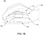
- FIG. 1B illustrates a side view of an adjustable supporting assembly 100 for a user of a conventional mouse 102
- the adjustable supporting assembly 100 may include at least one height adjustment member 104, at least one finger adjustment member 106, and a width adjustment member 108.
- the at least one height adjustment member 104 (hereinafter also referred to as ⁇ height adjustment member 104') and at least one finger adjustment member 106 (hereinafter also referred to as ⁇ finger adjustment member 106') may be coupled to a body of the conventional mouse 102, wherein the height adjustment member 104 may include a dome shaped member 110 that is coupled to a base plate 112. Using the base plate 112, the height adjustment member 104 may be coupled to the body of the conventional mouse 102.
- Each height adjustment member 104 may be capable of increasing or decreasing the height of the dome shaped member 110 which is attached to the base plate 112.
- the dome shaped member 110 may be a sheet member adapted for independent palm support to provide the appearance of a single piece of mouse body.
- the sheet member may be made of a material comprising fabric, rubber, any stretchy material, and so forth. Embodiments of the present invention are intended to include or otherwise cover any type of sheet including known, related art, and/or later developed technologies.
- the dome shaped member 110 may be flexible in nature.
- the base plate 112 may also be flexible in nature to accommodate a shape as per the body of the conventional mouse 102.
- the base plate 112, along its bottom surface may include a means for attaching the height adjustment member 104 to the body of the conventional mouse 102.
- the means for attaching may include, but not limited to, sticky material, such as glue; hook and loop attachments, elastic, or the like.
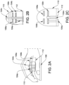
- the at least one height adjustment member 104 may further include one or more screws 114n that extends from the base plate 112 to an interior of the dome shaped member 110, as seen in FIGS. 2A-2C .
- the screw 114n may be located in the middle of the base plate 112 to extend within the interior of the dome shaped member 110 up to a maximum height of the dome shaped member 110 for adjusting height range of the dome shaped member 110.
- the finger adjustment members 106a-106b may be protruding laterally from the height adjustment member 104 for supporting fingers of the user.
- the height adjustment member 104 may include slots 104b in which the finger adjustment members 106a-106b may in inserted to protrude laterally from the height adjustment member 104 for supporting fingers of the user.
- the finger adjustment member 106a-106b may be adjusted in a forward direction, a backward direction, and in a side-to-side direction within the slots 104b.
- the finger adjustment member 106a-106b may also be adjusted vertically to adjust the height thereof.
- the height adjustment member 104 may further include one or more screws 104a that extends from the base plate 112 to the interior of the dome shaped member 110 and end at the finger adjustment member 106a-106b, as seen in FIGS. 2A-2C .
- the screw 104a may be screwed-in or screwed-out from the base plate 112 to adjust the height range of the finger adjustment member 106a-106b.
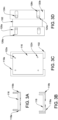
- the width adjustment member 108 may be adapted to be detachably coupled to a base portion of the conventional mouse 102.
- the width adjustment member 108 may be configured to be adjusted along a width of the convention mouse 102 for providing finger support, particularly, to thumb and pinky finger of the user, independently from either side of the conventional mouse 102.
- the width adjustment member 108 may include a receptacle member 116 and a pair of adjusting plates 118a-118b.
- the receptacle member 116 adapted to receive the base of the conventional mouse 102.
- the receptacle member 116 and the pair of adjusting plates 118a-118b are coupled to each other such that the pair of adjusting plates 118a-118b may be adjusted laterally (sidewise) with respect to the receptacle member 116.
- the receptacle member 116 may include a plurality of holes 122a-122n.
- each plate of the pair of adjusting plates 118a-118b may be include longitudinal slots 126a-126n.
- the plurality of holes 122a-122n of the receptacle member 116 and the longitudinal slots 126a-126n are arranged to receive screws 124a-124n.
- the screws124a-124n extend laterally along the longitudinal slots 126a-126n and the plurality of holes 122a-122n to obtain operatively engaging connection between the receptacle member 116 and the pair of adjusting plates 118a-118b.
- the pair of adjusting plates 118a-118b may be extended laterally from the receptacle member 116 by loosening or tightening the screws 124a-124n.
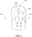
- FIG. 4 illustrates a top view of the of the adjustable supporting assembly 100 coupled to the body of the conventional mouse.
- the finger adjustment member 106 may be adapted to be adjusted in the forward direction, in the backward direction, and in a side-by-side direction with respect to the conventional mouse 102.
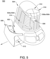
- FIG. 5 illustrates a perspective view of an adjustable supporting assembly 500 for a user of a conventional mouse 502, according to another embodiment of the present invention.
- the adjustable supporting assembly 500 of the present invention also includes at least one height adjustment member 504, at least one finger adjustment member 506, and a width adjustment member 508.
- Constructional features of the width adjustment member 508 is similar to the constructional features of the width adjustment member 108 as described in conjunction with FIGS. 3A to 3D and is avoided herein from further explanation for the sake of brevity.
- the least one height adjustment member 504 of this embodiment may comprise one or more adjustment components 504a-504n, whereby one or more adjustment components 504a-504n may be stacked together for adjusting the height of the least one height adjustment member 504 for the palm comfort.
- the height adjustment member 504 may be a mushroom shaped height adjustment member.
- the one or more adjustment components 504a-504n may be a brick-like structure, as seen in FIG. 5 , wherein each layer of height in the height adjustment member 504 may be formed by arranging multiple adjustment components 504a-504n.
- any one adjustment components 504a-504n may be removed from the height adjustment member 504 to create one or more slots, in which the finger adjustment members 506 may be inserted for protruding laterally from the height adjustment member 504 for providing support to the finger.
- the one or more adjustment components 504a-504n may be a layer-like structure, as seen in FIGS. 6A and 6B , wherein each layer of height in the height adjustment member 504 may be formed by arranging a single adjustment components 504a-504n.
- any one adjustment components 504a-504n may include one or more slots, in which the finger adjustment members 506 may be inserted for protruding laterally from the height adjustment member 504 for providing support to the finger.
- the height adjustment member 504 may be cut into a preset way and form as thick layers of EVA foam which are layered on top of each other at a specific height. A user may lay his/her hand on top of that layered specific height, thereby supporting palm and fingers.
- the adjustable supporting assembly 500 may further include a knuckle supporting member 512, which may be mounted on the height adjustment member 504.
- the knuckle supporting member 512 may comprise a slot to incorporate a screw to be extended laterally along the slot for being adjusted as per the user preference.
- the knuckle supporting member 512 is along extreme backside of the height adjustment member 504, which when required may be slid to extreme forward of the height adjustment member 504 for supporting a palm area beneath the knuckle of the user, as seen in FIG. 6C .
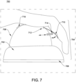
- the adjustable supporting assembly 700 may include at least one height adjustment member 708, at least one finger adjustment member 710 and a width adjustment assembly 706, as seen in FIG. 7 .
- Constructional features of the height adjustment member 708 or the constructional features of the width adjustment member 706 may be similar to the constructional features of the height adjustment member or the constructional features of the width adjustment member, as described in conjunction with FIGS. 3A to 3D , and FIGS. 5 , 6A-6B and are avoided herein from further explanation for the sake of brevity.
- the least one finger adjustment member 710 may be pivotally coupled to the height adjustment member 708 via a hinge 712. Further, the at least one height adjustment member 708 may be elevated and lowered, independent of the finger supports, using the one or more adjustment screws 714.
- the finger support member 710 may also be utilized to adjust forward and backward adjustment as well as side to side. The side to side may also be pivoted from the point of one or more adjustment screws 714.
- the finger support member 710 may be approximately 1mm thick, 5mm to 25 mm wide, and span the length of the user's fingertip to the heel of the user's palm.
- the finger support member 710 may be made of semi-flexible material such as, but not limiting to, plastic, rubber, and so forth.
- the finger support member 710 may be comfortable to touch.
- the adjustability may be approximately 40mm forward and backward and 5 to 10mm side to side at the contact point.
- the finger support member 710 may be for two or three fingers. When there are two fingers (Index and middle finger) each with adjustment screw 714 or other, extending forward toward the front of a convention mouse 702.
- a two-part assembly for a user of a conventional mouse may be provided in which in one part may include a palm and finger supporting assembly having at least one height adjustment member and at least one finger adjustment member, and another part may include a width adjustment assembly.
- a palm and finger supporting assembly having at least one height adjustment member and at least one finger adjustment member
- another part may include a width adjustment assembly.
Landscapes
- Engineering & Computer Science (AREA)
- General Engineering & Computer Science (AREA)
- Theoretical Computer Science (AREA)
- Human Computer Interaction (AREA)
- Physics & Mathematics (AREA)
- General Physics & Mathematics (AREA)
- Position Input By Displaying (AREA)
Applications Claiming Priority (1)
| Application Number | Priority Date | Filing Date | Title |
|---|---|---|---|
| US202163294079P | 2021-12-28 | 2021-12-28 |
Publications (2)
| Publication Number | Publication Date |
|---|---|
| EP4206873A2 true EP4206873A2 (fr) | 2023-07-05 |
| EP4206873A3 EP4206873A3 (fr) | 2023-09-06 |
Family
ID=84602178
Family Applications (1)
| Application Number | Title | Priority Date | Filing Date |
|---|---|---|---|
| EP22216484.0A Pending EP4206873A3 (fr) | 2021-12-28 | 2022-12-23 | Ensemble de support réglable pour un utilisateur de souris ergonomique, et souris d'ordinateur ergonomique réglable |
Country Status (5)
| Country | Link |
|---|---|
| US (1) | US20230205327A1 (fr) |
| EP (1) | EP4206873A3 (fr) |
| JP (1) | JP2023098691A (fr) |
| CN (1) | CN220455806U (fr) |
| CA (1) | CA3184656A1 (fr) |
Families Citing this family (1)
| Publication number | Priority date | Publication date | Assignee | Title |
|---|---|---|---|---|
| CN116931748B (zh) * | 2023-07-31 | 2024-02-09 | 深圳市博仪创新科技有限公司 | 一种智能型光控无线鼠标 |
Family Cites Families (2)
| Publication number | Priority date | Publication date | Assignee | Title |
|---|---|---|---|---|
| CN112181179A (zh) * | 2014-12-02 | 2021-01-05 | 康杜尔设计公司 | 可调整鼠标 |
| EP3673350B1 (fr) * | 2017-08-21 | 2024-03-27 | Contour Innovations LLC | Souris réglable |
-
2022
- 2022-12-23 EP EP22216484.0A patent/EP4206873A3/fr active Pending
- 2022-12-23 CA CA3184656A patent/CA3184656A1/fr active Pending
- 2022-12-26 JP JP2022209068A patent/JP2023098691A/ja active Pending
- 2022-12-27 US US18/088,821 patent/US20230205327A1/en active Pending
- 2022-12-28 CN CN202223517145.8U patent/CN220455806U/zh active Active
Also Published As
| Publication number | Publication date |
|---|---|
| JP2023098691A (ja) | 2023-07-10 |
| CN220455806U (zh) | 2024-02-06 |
| EP4206873A3 (fr) | 2023-09-06 |
| CA3184656A1 (fr) | 2023-06-28 |
| US20230205327A1 (en) | 2023-06-29 |
Similar Documents
| Publication | Publication Date | Title |
|---|---|---|
| US6362811B1 (en) | Ergonomic computer mouse | |
| US5576733A (en) | Ergonomic computer mouse | |
| US5788195A (en) | Ergonomic data entry device | |
| US6545667B1 (en) | Apparatus for a convenient and comfortable cursor control device | |
| US6724366B2 (en) | Thumb actuated x-y input device | |
| US9063587B2 (en) | Computer input device with ergonomically formed and positioned actuators | |
| CA2529466C (fr) | Dispositif de pointage ergonomique | |
| US7701443B2 (en) | Ergonomic computer mouse | |
| US6064371A (en) | PC mouse incorporating adjustability | |
| JPH06195170A (ja) | 人間工学的ポインティングデバイス | |
| US6532002B2 (en) | Orthopedic computer mouse | |
| US6300941B1 (en) | Orthopedic computer mouse | |
| EP4206873A2 (fr) | Ensemble de support réglable pour un utilisateur de souris ergonomique, et souris d'ordinateur ergonomique réglable | |
| US20060007152A1 (en) | Computer finger mouse | |
| EP1055221A1 (fr) | Peripherique d'entree a pointage, actionne par le pouce et destine a un ordinateur | |
| CA2534662A1 (fr) | Souris ergonomique | |
| US6402100B1 (en) | Ergonomic lower arm support rest | |
| US20070285400A1 (en) | Palm attached touch-pad computer mouse | |
| US6549189B1 (en) | Method for operating a computer input device and keyboard | |
| US6031523A (en) | Meta-rest improved PC mouse | |
| US11256345B2 (en) | Hand operated computer input device with palm heel support | |
| US20040008184A1 (en) | Ergonomic electronic input device | |
| US20220244797A1 (en) | Hand Operated Computer Input Device With Palm Heel Support | |
| KR200262391Y1 (ko) | 인간 환경 공학의 컴퓨터 마우스 | |
| JPH11242557A (ja) | 人間工学的コンピュータ制御デバイス |
Legal Events
| Date | Code | Title | Description |
|---|---|---|---|
| PUAI | Public reference made under article 153(3) epc to a published international application that has entered the european phase |
Free format text: ORIGINAL CODE: 0009012 |
|
| STAA | Information on the status of an ep patent application or granted ep patent |
Free format text: STATUS: THE APPLICATION HAS BEEN PUBLISHED |
|
| AK | Designated contracting states |
Kind code of ref document: A2 Designated state(s): AL AT BE BG CH CY CZ DE DK EE ES FI FR GB GR HR HU IE IS IT LI LT LU LV MC ME MK MT NL NO PL PT RO RS SE SI SK SM TR |
|
| PUAL | Search report despatched |
Free format text: ORIGINAL CODE: 0009013 |
|
| AK | Designated contracting states |
Kind code of ref document: A3 Designated state(s): AL AT BE BG CH CY CZ DE DK EE ES FI FR GB GR HR HU IE IS IT LI LT LU LV MC ME MK MT NL NO PL PT RO RS SE SI SK SM TR |
|
| RIC1 | Information provided on ipc code assigned before grant |
Ipc: G06F 3/0354 20130101AFI20230803BHEP |
|
| STAA | Information on the status of an ep patent application or granted ep patent |
Free format text: STATUS: REQUEST FOR EXAMINATION WAS MADE |
|
| 17P | Request for examination filed |
Effective date: 20240228 |
|
| RBV | Designated contracting states (corrected) |
Designated state(s): AL AT BE BG CH CY CZ DE DK EE ES FI FR GB GR HR HU IE IS IT LI LT LU LV MC ME MK MT NL NO PL PT RO RS SE SI SK SM TR |