EP4205949A1 - Improved edge-banding machine and operating method thereof - Google Patents
Improved edge-banding machine and operating method thereof Download PDFInfo
- Publication number
- EP4205949A1 EP4205949A1 EP22215249.8A EP22215249A EP4205949A1 EP 4205949 A1 EP4205949 A1 EP 4205949A1 EP 22215249 A EP22215249 A EP 22215249A EP 4205949 A1 EP4205949 A1 EP 4205949A1
- Authority
- EP
- European Patent Office
- Prior art keywords
- glue
- bulkhead
- piece
- group
- advancement
- Prior art date
- Legal status (The legal status is an assumption and is not a legal conclusion. Google has not performed a legal analysis and makes no representation as to the accuracy of the status listed.)
- Granted
Links
Images

Classifications
-
- B—PERFORMING OPERATIONS; TRANSPORTING
- B29—WORKING OF PLASTICS; WORKING OF SUBSTANCES IN A PLASTIC STATE IN GENERAL
- B29C—SHAPING OR JOINING OF PLASTICS; SHAPING OF MATERIAL IN A PLASTIC STATE, NOT OTHERWISE PROVIDED FOR; AFTER-TREATMENT OF THE SHAPED PRODUCTS, e.g. REPAIRING
- B29C63/00—Lining or sheathing, i.e. applying preformed layers or sheathings of plastics; Apparatus therefor
- B29C63/0026—Lining or sheathing, i.e. applying preformed layers or sheathings of plastics; Apparatus therefor an edge face with strip material, e.g. a panel edge
-
- B—PERFORMING OPERATIONS; TRANSPORTING
- B27—WORKING OR PRESERVING WOOD OR SIMILAR MATERIAL; NAILING OR STAPLING MACHINES IN GENERAL
- B27D—WORKING VENEER OR PLYWOOD
- B27D5/00—Other working of veneer or plywood specially adapted to veneer or plywood
- B27D5/003—Other working of veneer or plywood specially adapted to veneer or plywood securing a veneer strip to a panel edge
Definitions
- the invention relates to an edge-banding machine, suitable for applying a finishing tape to a panel made of wood, metal, ceramic, plastic, glass, composite materials and the like, equipped with two or more glue pots, for containing and application of adhesives for gluing said tape.
- Edge-banding machines comprising two or more glue units, each comprising a glue pot for containing and applying glues.
- the adhesives contained in each of said glue pots may differ in type and/or cooler.
- the respective glue unit is moved in a direction perpendicular to the advancement direction of the piece and lying on the geometric plane passing through the advancement plane of the piece, so as to move said glue pot away from the advancement plane of said piece, and allow the replacement or maintenance operations with greater safety.
- the object of the present invention is to provide a beading machine which is able to allow the reduction of machine stops, increasing its productivity.
- a further object of the present invention is that to allow the actions of replacement of glue pots and maintenance of glue units, by an operator, in complete safety, avoiding stopping the machine.
- a machine for edge-banding at least one side surface or edge of a piece such as a panel made of wood, metal, glass, ceramic, composite materials, plastic or the like, by means of an edging tape, comprising an advancement plane for supporting and advancing said piece along an advancement direction; a first glue group, comprising a first glue tank, for containing a respective glue for edge-banding of said piece, wherein said first glue group is movable between an operating position, wherein said first glue group is capable of dispensing glue on said piece and/or said edging tape, and an exclusion position, wherein said first glue group is spaced from said advancement plane with respect to said operating position to allow an operator to carry out at least one operation on said gluing unit, in particular on said glue tank; and at least a second gluing unit, comprising a second glue tank, for containing a respective glue for the edge-banding of said piece; characterized in that it comprises at least one bulkhead movable between a rest position, wherein
- said bulkhead is moved in a direction parallel to an advancement direction of said piece to pass from said rest position to said working position and vice-versa.
- said first gluing unit may be moved in a direction perpendicular to said advancement direction of said piece to pass from said operating position to said exclusion position and vice-versa.
- said first glue group may comprise a first actuator, such as an actuator of the pneumatic, electric or hydraulic type, to move said first glue group from said operating position to said exclusion position and vice-versa.
- a first actuator such as an actuator of the pneumatic, electric or hydraulic type
- said machine may comprise a first sliding actuator, coupled to said bulkhead, to move said bulkhead from said rest position to said working position and/or vice-versa.
- said at least one second glue group may be movable between a respective operating position, wherein said second glue group is capable of dispensing glue on said piece and/or on said edging tape, and a respective exclusion position, wherein said second glue unit is spaced from said advancement plane with respect to said respective operating position, and said bulkhead is movable between said rest position and a further working position, wherein, when said second glue unit is in the respective exclusion position, said bulkhead is interposed between said second glue unit and said advancement plane.
- said second glue group may comprise a second actuator, such as a pneumatic, electric or hydraulic actuator, to move said second glue group from said respective operative position to said respective exclusion position and/or vice-versa.
- a second actuator such as a pneumatic, electric or hydraulic actuator
- said machine may comprise a second sliding actuator, coupled to said bulkhead, to move said bulkhead from said rest position to said further working position and/or vice-versa.
- said first sliding actuator may move said bulkhead from said rest position to said further working position and/or vice-versa.
- second glue group may be movable between a respective operating position, wherein said second glue group is capable of dispensing glue on said piece and/or said edging tape, and a respective exclusion position, wherein said second glue unit is spaced from said advancement plane with respect to said respective operating position to allow an operator to carry out at least one operation on said glue unit, in particular on said glue tank
- said machine may comprise a second bulkhead, movable between a respective rest position, wherein said second bulkhead is not interposed between said second glue group and said advancement plane, and a respective working position, wherein, when said second glue group is in said respective exclusion position, said second bulkhead is interposed between de the second glue unit and said advancement plane, so as to create a safety barrier for an operator who carries out said at least one operation.
- It is further object of the present invention a method for edge-banding at least one side surface or an edge of a piece, such as a panel made of wood, metal, glass, ceramic, composite materials, plastic or the like, by means of an edging tape comprising the steps of: (a) moving said piece by means of an advancement plane along an advancement direction; (b) applying glue on said piece and/or on said edging tape by means of a first glue group placed in an operative position; (c) moving said first glue group from said operating position to said exclusion position, wherein said first glue group is spaced from said advancement plane with respect to said operating position; and (d) moving a bulkhead between a rest position, wherein said bulkhead is not interposed between said first glue unit and said advancement plane, and a working position, wherein, when said first glue group is in said exclusion position, said bulkhead is interposed between said first glue group and said advancement plane.
- a machine M can be observed for edging of at least one lateral surface or edge of a piece P, such as a panel made of wood, metal, glass, ceramic, composite materials, plastic or the like, by a edging tape N.
- the machine M comprises an advancement plane 4 for supporting and advancing the piece P, a first glue unit 1, for gluing said edging tape on the piece P with a respective glue, and at least one second gluing unit 2, for gluing the edging tape on piece P, with a glue the same as the first or different in type and/or color.
- the machine M also includes a magazine 5 for containing said edging tape N.
- the advancement plane 4 comprises a conveyor belt 41, which allows the advancement of the piece P to be edge-banded along an advancement direction X, so that said piece P can be subjected to various machining.
- These machining can be at least one of the following processes: rectification of the panel to be edge-banded, gluing of the finishing edge on the narrow side of the panel, end milling, trimming, gleaning of the edge, rounding and scraping of the applied edge, and scraping of any excess glue from the bottom and top surfaces of the panel and from the applied edge-band.
- These machining are performed by specific groups or working units generally arranged in series on one side of the advancement plane 4.
- the advancement plane 4 comprises a belt or transport rollers. In other embodiments, the advancement plane can be moved by advancement chains.
- the first glue unit 1 comprises a first glue pot 11, for containing a first type of glue, in particular, but not necessarily, a solid glue.
- the first glue group 1 also comprises heating means, for heating said first glue, a first glue roller 13, for applying said first glue on said piece P and/or said edging tape N.
- said first glue pot 11 is placed in the upper or in the upper part with respect to said first glue unit 1, and said first glue roller 13 is placed in the lower or in the lower part of said first glue unit 1.
- Said heating means are arranged in the first glue unit 1, so that, in use, the glue contained in the first glue pot 11 is heated, causing said glue to pass from a solid state to a liquid state.
- the structure of the second gluing unit 2 is similar to that of the first glue unit 1.
- Said second gluing unit 2 in fact, comprises a second glue tank 21, for containing a second glue, in particular a solid glue, means for heating said second glue, a second glue roller 23 for applying said second glue on the piece P and/or on the edging tape N.
- said first glue unit 1 is equipped with a first actuator 12, in particular an actuator of the pneumatic, electric or hydraulic type.
- the first actuator 12 is configured to move the glue unit 1 from an operating position, in which the first glue unit 1 is capable of dispensing glue on the piece P and/or on the edging tape N, to an exclusion position, in which the first glue group 1 is spaced from said advancement plane 4 with respect to said operating position, and vice versa.
- the first glue unit 1 is equipped with a first actuator 12
- the second gluing unit 2 is equipped with a second actuator 22, in particular, an actuator of the pneumatic, electric or hydraulic type, having a function analogous to that of the first actuator 12.
- the machine M is also equipped with a bulkhead 3, which is in turn equipped with a first sliding actuator 6, in particular an actuator of the pneumatic, electric or hydraulic type, and movable in a direction parallel to said advancement direction X of said piece P.
- a first sliding actuator 6 in particular an actuator of the pneumatic, electric or hydraulic type, and movable in a direction parallel to said advancement direction X of said piece P.
- the first actuator 12 moves said first glue unit 1 in such a way that passes from the operating position to the exclusion position, thus finding itself spaced from the advancement plane 4, on which the pieces P to be machined continue to slide and to be moved in the advancement direction X.
- the first glue group 1 can be moved manually.
- the bulkhead 3 is moved, by means of said first sliding actuator 6, from a rest position, in which said bulkhead 3 is not interposed between the first glue unit 1, and the advancement plane 4, and a working position in which, when the first glue group 1 is in said exclusion position, the bulkhead 3 is interposed between said first glue group 1 and the advancement plane 4.
- the bulkhead 3 can be moved manually.
- the bulkhead 3 is moved again by the first sliding actuator 6, so that it is not placed between the first glue unit 1 and the advancement plane 4, so that the first actuator 12 can move the first glue group 1 from the extracted position to the operating position.
- the second actuator 22 moves the second gluing unit 2, preferably always in a direction perpendicular to the advancement direction X, from a respective operating position, in which the second gluing unit 2 is capable of dispensing glue on the piece P and/or said edging tape N, and a respective exclusion position, in which the second gluing unit 2 is spaced from the advancement plane 4 with respect to said respective operating position, to allow possible glue tank 21 replacement operations or maintenance of the gluing unit 2 itself.
- the second gluing unit 2 can be moved manually.
- the bulkhead 3 can be moved, by means of said first sliding actuator 6, from the rest position to a further working position, in which, when the second gluing unit 2 is in the respective exclusion position, the bulkhead 3 is interposed between the second gluing unit 2 and the advance plane 4.
- the bulkhead 3 can be moved from said rest position to said further working position by means of a second sliding actuator.
- the second gluing unit 2 is movable between a respective operating position, in which the second gluing unit 2 is capable of dispensing glue on the piece P and/or on the edging tape N, and a respective exclusion position, in which the second gluing unit 2 is spaced apart from the advancement plane 4 with respect to said respective operating position.
- the machine M comprises a second bulkhead, movable between a respective rest position, which is not interposed between the second gluing unit 2 and the advancement plane 4, and a respective working position, in which, when said second gluing unit 2 is in the respective exclusion position, the second bulkhead is interposed between the second gluing unit 2 and said advance plane 4, so as to allow for any replacement of the glue tank 21 or the execution of maintenance operations.
- FIGS. 5 and 6 show an edge-banding machine M structurally analogous to the one shown schematically in figures 1-4 . Similar parts have been indicated with similar reference numbers.
- the glue units 1 and 2 and the tape magazine 5 can be recognized in particular.
- An advantage of the present invention is that of reducing machine stops in edge-banding machines equipped with at least two glue units, due to the replacement of the glue pots and/or maintenance of the glue units themselves.
- Another advantage of the invention is that of making it possible to replace the glue pots and maintain the glue units without endangering the operator assigned to said operations.
Landscapes
- Engineering & Computer Science (AREA)
- Life Sciences & Earth Sciences (AREA)
- Manufacturing & Machinery (AREA)
- Mechanical Engineering (AREA)
- Wood Science & Technology (AREA)
- Forests & Forestry (AREA)
- Organic Low-Molecular-Weight Compounds And Preparation Thereof (AREA)
- Diaphragms For Electromechanical Transducers (AREA)
- Dental Tools And Instruments Or Auxiliary Dental Instruments (AREA)
- Package Closures (AREA)
- Coating Apparatus (AREA)
Abstract
Description
- The present invention relates to an improved edge-beading machine and operating method thereof.
- More specifically, the invention relates to an edge-banding machine, suitable for applying a finishing tape to a panel made of wood, metal, ceramic, plastic, glass, composite materials and the like, equipped with two or more glue pots, for containing and application of adhesives for gluing said tape.
- In the following, the description will be addressed to an edge banding machine for wooden panels and similar materials. However, it is clear that the same description should not be considered limited to this specific use.
- As is well known, there are currently edge-banding machines in which a piece, in particular a panel made of wood, composite material, plastic, chipboard or other material, is moved in an advancement direction through an advancement plane, and is subjected, while advancing, to various machining, such as grinding, edge gluing, butting, trimming, edge gleaning, edge rounding, edge scraping and scraping off any excess glue.
- Edge-banding machines are also known comprising two or more glue units, each comprising a glue pot for containing and applying glues. The adhesives contained in each of said glue pots may differ in type and/or cooler.
- In these machines, when it is necessary to replace a glue pot or to carry out maintenance on the glue units, in which the glue pots are installed, the machine must be stopped. In fact, for safety reasons, it is necessary to prevent the movement and passage of the panels during the operator's intervention.
- In particular, during the operations to replace a glue pot, the respective glue unit is moved in a direction perpendicular to the advancement direction of the piece and lying on the geometric plane passing through the advancement plane of the piece, so as to move said glue pot away from the advancement plane of said piece, and allow the replacement or maintenance operations with greater safety.
- It is evident that this is detrimental in economic terms, since, with each replacement of a finished glue pot or in the case of ordinary maintenance, the machining of the pieces and therefore production must be interrupted.
- In the light of the above, it is, therefore, scope of the present invention to provide a beading machine which overcomes the drawbacks of the prior art.
- In particular, the object of the present invention is to provide a beading machine which is able to allow the reduction of machine stops, increasing its productivity.
- A further object of the present invention is that to allow the actions of replacement of glue pots and maintenance of glue units, by an operator, in complete safety, avoiding stopping the machine.
- It is therefore object of the present invention a machine for edge-banding at least one side surface or edge of a piece, such as a panel made of wood, metal, glass, ceramic, composite materials, plastic or the like, by means of an edging tape, comprising an advancement plane for supporting and advancing said piece along an advancement direction; a first glue group, comprising a first glue tank, for containing a respective glue for edge-banding of said piece, wherein said first glue group is movable between an operating position, wherein said first glue group is capable of dispensing glue on said piece and/or said edging tape, and an exclusion position, wherein said first glue group is spaced from said advancement plane with respect to said operating position to allow an operator to carry out at least one operation on said gluing unit, in particular on said glue tank; and at least a second gluing unit, comprising a second glue tank, for containing a respective glue for the edge-banding of said piece; characterized in that it comprises at least one bulkhead movable between a rest position, wherein said bulkhead is not interposed between said first gluing unit and said advancement plane, and a working position, wherein, when said first glue group and in said exclusion position, said bulkhead is interposed between said first glue group and said advancement plane, so as to create a safety barrier for an operator who carries out said at least one operation.
- Always according to the invention, said bulkhead is moved in a direction parallel to an advancement direction of said piece to pass from said rest position to said working position and vice-versa.
- Still according to the invention, said first gluing unit may be moved in a direction perpendicular to said advancement direction of said piece to pass from said operating position to said exclusion position and vice-versa.
- Advantageously according to the invention, said first glue group may comprise a first actuator, such as an actuator of the pneumatic, electric or hydraulic type, to move said first glue group from said operating position to said exclusion position and vice-versa.
- Preferably according to the invention, said machine may comprise a first sliding actuator, coupled to said bulkhead, to move said bulkhead from said rest position to said working position and/or vice-versa.
- Further according to the invention, said at least one second glue group may be movable between a respective operating position, wherein said second glue group is capable of dispensing glue on said piece and/or on said edging tape, and a respective exclusion position, wherein said second glue unit is spaced from said advancement plane with respect to said respective operating position, and said bulkhead is movable between said rest position and a further working position, wherein, when said second glue unit is in the respective exclusion position, said bulkhead is interposed between said second glue unit and said advancement plane.
- Always according to the invention, said second glue group may comprise a second actuator, such as a pneumatic, electric or hydraulic actuator, to move said second glue group from said respective operative position to said respective exclusion position and/or vice-versa.
- Still according to the invention, said machine may comprise a second sliding actuator, coupled to said bulkhead, to move said bulkhead from said rest position to said further working position and/or vice-versa.
- Advantageously according to the invention, said first sliding actuator may move said bulkhead from said rest position to said further working position and/or vice-versa.
- Further according to the invention, second glue group may be movable between a respective operating position, wherein said second glue group is capable of dispensing glue on said piece and/or said edging tape, and a respective exclusion position, wherein said second glue unit is spaced from said advancement plane with respect to said respective operating position to allow an operator to carry out at least one operation on said glue unit, in particular on said glue tank, and said machine may comprise a second bulkhead, movable between a respective rest position, wherein said second bulkhead is not interposed between said second glue group and said advancement plane, and a respective working position, wherein, when said second glue group is in said respective exclusion position, said second bulkhead is interposed between de the second glue unit and said advancement plane, so as to create a safety barrier for an operator who carries out said at least one operation.
- It is further object of the present invention a method for edge-banding at least one side surface or an edge of a piece, such as a panel made of wood, metal, glass, ceramic, composite materials, plastic or the like, by means of an edging tape, comprising the steps of: (a) moving said piece by means of an advancement plane along an advancement direction; (b) applying glue on said piece and/or on said edging tape by means of a first glue group placed in an operative position; (c) moving said first glue group from said operating position to said exclusion position, wherein said first glue group is spaced from said advancement plane with respect to said operating position; and (d) moving a bulkhead between a rest position, wherein said bulkhead is not interposed between said first glue unit and said advancement plane, and a working position, wherein, when said first glue group is in said exclusion position, said bulkhead is interposed between said first glue group and said advancement plane.
- The present invention will be now described, for illustrative but not limitative purposes, according to its preferred embodiments, with particular reference to the figures of the enclosed drawings, wherein:
-
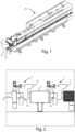
figure 1 shows a rear perspective view of an improved edge-bending machine according to the invention; -
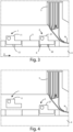
figure 2 shows a schematic front view of a detail of the machine offigure 1 , in which some glue units are shown; -
figure 3 shows a schematic top view of a detail of the machine offigure 1 , in which some glue units are shown; -
figure 4 shows a schematic top view of the same detail represented infigure 3 , in which the operation of said glue-units according to the invention is schematized; -
figure 5 shows a front view of the same detail offigure 2 shown in greater detail; and -
figure 6 shows a top view of the same detail offigure 3 shown in greater detail. - In the various figures, similar parts will be indicated with the same reference numbers.
- With reference to
figures 1, 2 and3 , a machine M can be observed for edging of at least one lateral surface or edge of a piece P, such as a panel made of wood, metal, glass, ceramic, composite materials, plastic or the like, by a edging tape N. - The machine M comprises an
advancement plane 4 for supporting and advancing the piece P, afirst glue unit 1, for gluing said edging tape on the piece P with a respective glue, and at least onesecond gluing unit 2, for gluing the edging tape on piece P, with a glue the same as the first or different in type and/or color. The machine M also includes amagazine 5 for containing said edging tape N. - The
advancement plane 4 comprises aconveyor belt 41, which allows the advancement of the piece P to be edge-banded along an advancement direction X, so that said piece P can be subjected to various machining. These machining can be at least one of the following processes: rectification of the panel to be edge-banded, gluing of the finishing edge on the narrow side of the panel, end milling, trimming, gleaning of the edge, rounding and scraping of the applied edge, and scraping of any excess glue from the bottom and top surfaces of the panel and from the applied edge-band. These machining are performed by specific groups or working units generally arranged in series on one side of theadvancement plane 4. - In other embodiments, various series of different working groups or units may be provided, according to the technical machining requirements.
- In some embodiments the
advancement plane 4 comprises a belt or transport rollers. In other embodiments, the advancement plane can be moved by advancement chains. - The
first glue unit 1 comprises afirst glue pot 11, for containing a first type of glue, in particular, but not necessarily, a solid glue. Thefirst glue group 1 also comprises heating means, for heating said first glue, afirst glue roller 13, for applying said first glue on said piece P and/or said edging tape N. - As generally occurs in glue units such as the one described, said
first glue pot 11 is placed in the upper or in the upper part with respect to saidfirst glue unit 1, and saidfirst glue roller 13 is placed in the lower or in the lower part of saidfirst glue unit 1. - Said heating means are arranged in the
first glue unit 1, so that, in use, the glue contained in thefirst glue pot 11 is heated, causing said glue to pass from a solid state to a liquid state. - The structure of the
second gluing unit 2 is similar to that of thefirst glue unit 1. Saidsecond gluing unit 2, in fact, comprises asecond glue tank 21, for containing a second glue, in particular a solid glue, means for heating said second glue, asecond glue roller 23 for applying said second glue on the piece P and/or on the edging tape N. - In a first preferred embodiment, said
first glue unit 1 is equipped with afirst actuator 12, in particular an actuator of the pneumatic, electric or hydraulic type. Thefirst actuator 12 is configured to move theglue unit 1 from an operating position, in which thefirst glue unit 1 is capable of dispensing glue on the piece P and/or on the edging tape N, to an exclusion position, in which thefirst glue group 1 is spaced from saidadvancement plane 4 with respect to said operating position, and vice versa. - In a second preferred embodiment, the
first glue unit 1 is equipped with afirst actuator 12, and thesecond gluing unit 2 is equipped with asecond actuator 22, in particular, an actuator of the pneumatic, electric or hydraulic type, having a function analogous to that of thefirst actuator 12. - The machine M is also equipped with a
bulkhead 3, which is in turn equipped with a first slidingactuator 6, in particular an actuator of the pneumatic, electric or hydraulic type, and movable in a direction parallel to said advancement direction X of said piece P. - The operation of the improved edge-banding machine M described above takes is follows.
- With reference to
figure 4 , in the first embodiment, when it is necessary to replace theglue pot 11 of thefirst glue unit 1, or carry out any maintenance on theglue unit 1 itself, thefirst actuator 12 moves saidfirst glue unit 1 in such a way that passes from the operating position to the exclusion position, thus finding itself spaced from theadvancement plane 4, on which the pieces P to be machined continue to slide and to be moved in the advancement direction X. - In other embodiments the
first glue group 1 can be moved manually. - With reference to the aforementioned first preferred embodiment, moreover, the
bulkhead 3 is moved, by means of said first slidingactuator 6, from a rest position, in which saidbulkhead 3 is not interposed between thefirst glue unit 1, and theadvancement plane 4, and a working position in which, when thefirst glue group 1 is in said exclusion position, thebulkhead 3 is interposed between saidfirst glue group 1 and theadvancement plane 4. - In further embodiments the
bulkhead 3 can be moved manually. - In this way an operator can replace the glue pot or carry out any maintenance operation, suitably protected from the moving parts of the machine M, such as the working units or the
advancement plane 4. - Once the replacement or maintenance operations have been completed, the
bulkhead 3 is moved again by the first slidingactuator 6, so that it is not placed between thefirst glue unit 1 and theadvancement plane 4, so that thefirst actuator 12 can move thefirst glue group 1 from the extracted position to the operating position. - In the second embodiment described, the
second actuator 22 moves thesecond gluing unit 2, preferably always in a direction perpendicular to the advancement direction X, from a respective operating position, in which thesecond gluing unit 2 is capable of dispensing glue on the piece P and/or said edging tape N, and a respective exclusion position, in which thesecond gluing unit 2 is spaced from theadvancement plane 4 with respect to said respective operating position, to allowpossible glue tank 21 replacement operations or maintenance of thegluing unit 2 itself. - In other embodiments the
second gluing unit 2 can be moved manually. - In this embodiment of the machine M the
bulkhead 3 can be moved, by means of said first slidingactuator 6, from the rest position to a further working position, in which, when thesecond gluing unit 2 is in the respective exclusion position, thebulkhead 3 is interposed between thesecond gluing unit 2 and theadvance plane 4. - In other embodiments the
bulkhead 3 can be moved from said rest position to said further working position by means of a second sliding actuator. - In a third embodiment of the machine M, the
second gluing unit 2 is movable between a respective operating position, in which thesecond gluing unit 2 is capable of dispensing glue on the piece P and/or on the edging tape N, and a respective exclusion position, in which thesecond gluing unit 2 is spaced apart from theadvancement plane 4 with respect to said respective operating position. Furthermore, the machine M comprises a second bulkhead, movable between a respective rest position, which is not interposed between thesecond gluing unit 2 and theadvancement plane 4, and a respective working position, in which, when saidsecond gluing unit 2 is in the respective exclusion position, the second bulkhead is interposed between thesecond gluing unit 2 and saidadvance plane 4, so as to allow for any replacement of theglue tank 21 or the execution of maintenance operations. -
Figures 5 and 6 show an edge-banding machine M structurally analogous to the one shown schematically infigures 1-4 . Similar parts have been indicated with similar reference numbers. - The
glue units tape magazine 5 can be recognized in particular. - The arrangement of the
bulkhead 3 is also observed. - An advantage of the present invention is that of reducing machine stops in edge-banding machines equipped with at least two glue units, due to the replacement of the glue pots and/or maintenance of the glue units themselves.
- Another advantage of the invention is that of making it possible to replace the glue pots and maintain the glue units without endangering the operator assigned to said operations.
- The present invention has been described for illustrative but not limitative purposes, according to its preferred embodiments, but it is to be understood that modifications and/or changes can be introduced by those skilled in the art without departing from the relevant scope as defined in the enclosed claims.
Claims (11)
- Machine (M) for edge-banding at least one side surface or edge of a piece (P), such as a panel made of wood, metal, glass, ceramic, composite materials, plastic or the like, by means of an edging tape (N), comprisingan advancement plane (4) for supporting and advancing said piece (P) along an advancement direction (X);a first glue group (1), comprising a first glue tank (11), for containing a respective glue for edge-banding of said piece (P), wherein said first glue group (1) is movable between an operating position, wherein said first glue group (1) is capable of dispensing glue on said piece (P) and/or said edging tape (N), and an exclusion position, wherein said first glue group (1) is spaced from said advancement plane (4) with respect to said operating position to allow an operator to carry out at least one operation on said gluing unit (1), in particular on said glue tank (11); andat least a second gluing unit (2), comprising a second glue tank (21), for containing a respective glue for the edge-banding of said piece (P);characterized in that it comprises at least one bulkhead (3) movable between a rest position, wherein said bulkhead (3) is not interposed between said first gluing unit (1) and said advancement plane (4), and a working position, wherein, when said first glue group (1) and in said exclusion position, said bulkhead (3) is interposed between said first glue group (1) and said advancement plane (4), so as to create a safety barrier for an operator who carries out said at least one operation.
- Machine (M) according to the preceding claim, characterized in that said bulkhead (3) is moved in a direction parallel to an advancement direction (X) of said piece (P) to pass from said rest position to said working position and vice-versa.
- Machine (M) according to any one of the preceding claims, characterized in that said first gluing unit (1) is moved in a direction perpendicular to said advancement direction (X) of said piece (P) to pass from said operating position to said exclusion position and vice-versa.
- Machine (M) according to any one of the preceding claims, characterized in that said first glue group (1) comprises a first actuator (12), such as an actuator of the pneumatic, electric or hydraulic type, to move said first glue group (1) from said operating position to said exclusion position and vice-versa.
- Machine (M) according to any one of the preceding claims, characterized in that it comprises a first sliding actuator (6), coupled to said bulkhead (3), to move said bulkhead (3) from said rest position to said working position and/or vice-versa.
- Machine (M) according to any one of the preceding claims, characterizedin that said at least one second glue group (2) is movable between a respective operating position, wherein said second glue group (2) is capable of dispensing glue on said piece (P) and/or on said edging tape (N), and a respective exclusion position, wherein said second glue unit (2) is spaced from said advancement plane (4) with respect to said respective operating position, andin that said bulkhead (3) is movable between said rest position and a further working position,wherein, when said second glue unit (2) is in the respective exclusion position, said bulkhead (3) is interposed between said second glue unit (2) and said advancement plane (4).
- Machine (M) according to the preceding claim, characterized in that said second glue group (2) comprises a second actuator (22), such as a pneumatic, electric or hydraulic actuator, to move said second glue group (2) from said respective operative position to said respective exclusion position and/or vice-versa.
- Machine (M) according to any one of claims 6 or 7, characterized in that it comprises a second sliding actuator, coupled to said bulkhead (3), to move said bulkhead (3) from said rest position to said further working position and/or vice-versa.
- Machine (M) according to any one of claims 6 or 7, characterized in that said first sliding actuator (6) moves said bulkhead (3) from said rest position to said further working position and/or vice-versa.
- Machine (M) according to any one of claims 1 - 5, characterizedin that said second glue group (2) is movable between a respective operating position, wherein said second glue group (2) is capable of dispensing glue on said piece (P) and/or said edging tape (N), and a respective exclusion position, wherein said second glue unit (2) is spaced from said advancement plane (4) with respect to said respective operating position to allow an operator to carry out at least one operation on said glue unit (2), in particular on said glue tank (21), andin that it comprises a second bulkhead, movable between a respective rest position, wherein said second bulkhead is not interposed between said second glue group (2) and said advancement plane (4), and a respective working position, wherein, when said second glue group (2) is in said respective exclusion position, said second bulkhead is interposed between de the second glue unit (2) and said advancement plane (4), so as to create a safety barrier for an operator who carries out said at least one operation.
- Method for edge-banding at least one side surface or an edge of a piece (P), such as a panel made of wood, metal, glass, ceramic, composite materials, plastic or the like, by means of an edging tape (N), comprising the steps of:(a) moving said piece (P) by means of an advancement plane (4) along an advancement direction (X);(b) applying glue on said piece (P) and/or on said edging tape (N) by means of a first glue group (1) placed in an operative position;(c) moving said first glue group (1) from said operating position to said exclusion position, wherein said first glue group (1) is spaced from said advancement plane (4) with respect to said operating position; and(d) moving a bulkhead (3) between a rest position, wherein said bulkhead (3) is not interposed between said first glue unit (1) and said advancement plane (4), and a working position, wherein, when said first glue group (1) is in said exclusion position, said bulkhead (3) is interposed between said first glue group (1) and said advancement plane (4).
Applications Claiming Priority (1)
| Application Number | Priority Date | Filing Date | Title |
|---|---|---|---|
| IT102021000033107A IT202100033107A1 (en) | 2021-12-30 | 2021-12-30 | Improved edgebanding machine and its method of operation |
Publications (2)
| Publication Number | Publication Date |
|---|---|
| EP4205949A1 true EP4205949A1 (en) | 2023-07-05 |
| EP4205949B1 EP4205949B1 (en) | 2025-02-26 |
Family
ID=80685211
Family Applications (1)
| Application Number | Title | Priority Date | Filing Date |
|---|---|---|---|
| EP22215249.8A Active EP4205949B1 (en) | 2021-12-30 | 2022-12-21 | Improved edge-banding machine and operating method thereof |
Country Status (2)
| Country | Link |
|---|---|
| EP (1) | EP4205949B1 (en) |
| IT (1) | IT202100033107A1 (en) |
Citations (3)
| Publication number | Priority date | Publication date | Assignee | Title |
|---|---|---|---|---|
| WO2001007152A1 (en) * | 1999-07-27 | 2001-02-01 | Castle, Inc. | Edge banding apparatus and method |
| DE102006060269A1 (en) * | 2006-12-20 | 2008-06-26 | Büssing, Maik | Processing method for ageing of wooden boards for furniture, involves using welding/adhesive for application of coating materials on to narrow board surfaces |
| WO2016112232A1 (en) * | 2015-01-07 | 2016-07-14 | Snx Technologies Inc. | Automated edge band application for non-linear work pieces |
-
2021
- 2021-12-30 IT IT102021000033107A patent/IT202100033107A1/en unknown
-
2022
- 2022-12-21 EP EP22215249.8A patent/EP4205949B1/en active Active
Patent Citations (3)
| Publication number | Priority date | Publication date | Assignee | Title |
|---|---|---|---|---|
| WO2001007152A1 (en) * | 1999-07-27 | 2001-02-01 | Castle, Inc. | Edge banding apparatus and method |
| DE102006060269A1 (en) * | 2006-12-20 | 2008-06-26 | Büssing, Maik | Processing method for ageing of wooden boards for furniture, involves using welding/adhesive for application of coating materials on to narrow board surfaces |
| WO2016112232A1 (en) * | 2015-01-07 | 2016-07-14 | Snx Technologies Inc. | Automated edge band application for non-linear work pieces |
Also Published As
| Publication number | Publication date |
|---|---|
| IT202100033107A1 (en) | 2023-06-30 |
| EP4205949B1 (en) | 2025-02-26 |
Similar Documents
| Publication | Publication Date | Title |
|---|---|---|
| CN101890738B (en) | Method and device for coating workpieces | |
| US10328607B2 (en) | Machine for cutting stone material | |
| EP1773540B1 (en) | Machine for finishing an object such as a profiled element, a panel, or suchlike | |
| WO2021218258A1 (en) | Automatic edge banding machine, and control system and method therefor | |
| WO2021218256A1 (en) | Control system for automatic edge banding machine | |
| CN104889841A (en) | Stone surface machining tool | |
| ITMO20090126A1 (en) | EDGING MACHINE | |
| EP3170622B1 (en) | Machine for machining plates in a substantially vertical position, having a cup grinding tool which can be oriented around an axis orthogonal to the plane of the plate | |
| GB2138358A (en) | Process and apparatus for binding books | |
| WO2021218257A1 (en) | Machining method of automatic edge banding machine | |
| ITPN20080070A1 (en) | AUTOMATIC PANELING OF PANELS WITH DIFFERENT PERIMETER PROFILES | |
| EP3050657A2 (en) | Automated apparatus for processing panels made of wood-like material | |
| CN116079860A (en) | Intelligent square edge banding production line | |
| WO2014049424A1 (en) | Method and apparatus for making double panels | |
| CN107598368A (en) | Laser cutting machine | |
| EP3248745B1 (en) | Edge-banding machine provided with a milling device and operation method of said edge-banding machine | |
| EP4205949B1 (en) | Improved edge-banding machine and operating method thereof | |
| CN205238221U (en) | A hypotenuse rubber coating banding overlays device for automizing edging bag sealer | |
| CN105058858A (en) | High-speed full-automatic plastic box gluing machine | |
| CN212312279U (en) | Full-automatic servo straight edge bonding machine | |
| CN106903774B (en) | Door leaf edge strip gluing, pressing and trimming production line | |
| EP3827950B1 (en) | Machine for machining panels | |
| DE102010019346A1 (en) | Machine for edge gluing and edge processing of work piece plates made of wood or similar material, has machine bed, on which longitudinal slot is adjustable along | |
| IT201900001347A1 (en) | GLANING APPARATUS FOR FLAT SHEETS | |
| CN217020813U (en) | Finishing device about bag sealer |
Legal Events
| Date | Code | Title | Description |
|---|---|---|---|
| PUAI | Public reference made under article 153(3) epc to a published international application that has entered the european phase |
Free format text: ORIGINAL CODE: 0009012 |
|
| STAA | Information on the status of an ep patent application or granted ep patent |
Free format text: STATUS: THE APPLICATION HAS BEEN PUBLISHED |
|
| AK | Designated contracting states |
Kind code of ref document: A1 Designated state(s): AL AT BE BG CH CY CZ DE DK EE ES FI FR GB GR HR HU IE IS IT LI LT LU LV MC ME MK MT NL NO PL PT RO RS SE SI SK SM TR |
|
| STAA | Information on the status of an ep patent application or granted ep patent |
Free format text: STATUS: REQUEST FOR EXAMINATION WAS MADE |
|
| 17P | Request for examination filed |
Effective date: 20231207 |
|
| RBV | Designated contracting states (corrected) |
Designated state(s): AL AT BE BG CH CY CZ DE DK EE ES FI FR GB GR HR HU IE IS IT LI LT LU LV MC ME MK MT NL NO PL PT RO RS SE SI SK SM TR |
|
| GRAP | Despatch of communication of intention to grant a patent |
Free format text: ORIGINAL CODE: EPIDOSNIGR1 |
|
| STAA | Information on the status of an ep patent application or granted ep patent |
Free format text: STATUS: GRANT OF PATENT IS INTENDED |
|
| RIC1 | Information provided on ipc code assigned before grant |
Ipc: B27D 5/00 20060101ALI20240910BHEP Ipc: B29C 63/00 20060101AFI20240910BHEP |
|
| INTG | Intention to grant announced |
Effective date: 20240923 |
|
| GRAS | Grant fee paid |
Free format text: ORIGINAL CODE: EPIDOSNIGR3 |
|
| GRAA | (expected) grant |
Free format text: ORIGINAL CODE: 0009210 |
|
| STAA | Information on the status of an ep patent application or granted ep patent |
Free format text: STATUS: THE PATENT HAS BEEN GRANTED |
|
| AK | Designated contracting states |
Kind code of ref document: B1 Designated state(s): AL AT BE BG CH CY CZ DE DK EE ES FI FR GB GR HR HU IE IS IT LI LT LU LV MC ME MK MT NL NO PL PT RO RS SE SI SK SM TR |
|
| REG | Reference to a national code |
Ref country code: GB Ref legal event code: FG4D |
|
| REG | Reference to a national code |
Ref country code: CH Ref legal event code: EP |
|
| REG | Reference to a national code |
Ref country code: DE Ref legal event code: R096 Ref document number: 602022011072 Country of ref document: DE |
|
| REG | Reference to a national code |
Ref country code: IE Ref legal event code: FG4D |
|
| P01 | Opt-out of the competence of the unified patent court (upc) registered |
Free format text: CASE NUMBER: APP_18181/2025 Effective date: 20250415 |
|
| REG | Reference to a national code |
Ref country code: NL Ref legal event code: MP Effective date: 20250226 |
|
| PG25 | Lapsed in a contracting state [announced via postgrant information from national office to epo] |
Ref country code: RS Free format text: LAPSE BECAUSE OF FAILURE TO SUBMIT A TRANSLATION OF THE DESCRIPTION OR TO PAY THE FEE WITHIN THE PRESCRIBED TIME-LIMIT Effective date: 20250526 |
|
| PG25 | Lapsed in a contracting state [announced via postgrant information from national office to epo] |
Ref country code: FI Free format text: LAPSE BECAUSE OF FAILURE TO SUBMIT A TRANSLATION OF THE DESCRIPTION OR TO PAY THE FEE WITHIN THE PRESCRIBED TIME-LIMIT Effective date: 20250226 |
|
| PG25 | Lapsed in a contracting state [announced via postgrant information from national office to epo] |
Ref country code: PL Free format text: LAPSE BECAUSE OF FAILURE TO SUBMIT A TRANSLATION OF THE DESCRIPTION OR TO PAY THE FEE WITHIN THE PRESCRIBED TIME-LIMIT Effective date: 20250226 |
|
| PG25 | Lapsed in a contracting state [announced via postgrant information from national office to epo] |
Ref country code: ES Free format text: LAPSE BECAUSE OF FAILURE TO SUBMIT A TRANSLATION OF THE DESCRIPTION OR TO PAY THE FEE WITHIN THE PRESCRIBED TIME-LIMIT Effective date: 20250226 |
|
| REG | Reference to a national code |
Ref country code: LT Ref legal event code: MG9D |
|
| PG25 | Lapsed in a contracting state [announced via postgrant information from national office to epo] |
Ref country code: IS Free format text: LAPSE BECAUSE OF FAILURE TO SUBMIT A TRANSLATION OF THE DESCRIPTION OR TO PAY THE FEE WITHIN THE PRESCRIBED TIME-LIMIT Effective date: 20250626 Ref country code: NO Free format text: LAPSE BECAUSE OF FAILURE TO SUBMIT A TRANSLATION OF THE DESCRIPTION OR TO PAY THE FEE WITHIN THE PRESCRIBED TIME-LIMIT Effective date: 20250526 |
|
| PG25 | Lapsed in a contracting state [announced via postgrant information from national office to epo] |
Ref country code: NL Free format text: LAPSE BECAUSE OF FAILURE TO SUBMIT A TRANSLATION OF THE DESCRIPTION OR TO PAY THE FEE WITHIN THE PRESCRIBED TIME-LIMIT Effective date: 20250226 |
|
| PG25 | Lapsed in a contracting state [announced via postgrant information from national office to epo] |
Ref country code: HR Free format text: LAPSE BECAUSE OF FAILURE TO SUBMIT A TRANSLATION OF THE DESCRIPTION OR TO PAY THE FEE WITHIN THE PRESCRIBED TIME-LIMIT Effective date: 20250226 |
|
| PG25 | Lapsed in a contracting state [announced via postgrant information from national office to epo] |
Ref country code: PT Free format text: LAPSE BECAUSE OF FAILURE TO SUBMIT A TRANSLATION OF THE DESCRIPTION OR TO PAY THE FEE WITHIN THE PRESCRIBED TIME-LIMIT Effective date: 20250626 Ref country code: LV Free format text: LAPSE BECAUSE OF FAILURE TO SUBMIT A TRANSLATION OF THE DESCRIPTION OR TO PAY THE FEE WITHIN THE PRESCRIBED TIME-LIMIT Effective date: 20250226 |
|
| PG25 | Lapsed in a contracting state [announced via postgrant information from national office to epo] |
Ref country code: GR Free format text: LAPSE BECAUSE OF FAILURE TO SUBMIT A TRANSLATION OF THE DESCRIPTION OR TO PAY THE FEE WITHIN THE PRESCRIBED TIME-LIMIT Effective date: 20250527 Ref country code: BG Free format text: LAPSE BECAUSE OF FAILURE TO SUBMIT A TRANSLATION OF THE DESCRIPTION OR TO PAY THE FEE WITHIN THE PRESCRIBED TIME-LIMIT Effective date: 20250226 |
|
| PG25 | Lapsed in a contracting state [announced via postgrant information from national office to epo] |
Ref country code: SE Free format text: LAPSE BECAUSE OF FAILURE TO SUBMIT A TRANSLATION OF THE DESCRIPTION OR TO PAY THE FEE WITHIN THE PRESCRIBED TIME-LIMIT Effective date: 20250226 |
|
| PG25 | Lapsed in a contracting state [announced via postgrant information from national office to epo] |
Ref country code: SM Free format text: LAPSE BECAUSE OF FAILURE TO SUBMIT A TRANSLATION OF THE DESCRIPTION OR TO PAY THE FEE WITHIN THE PRESCRIBED TIME-LIMIT Effective date: 20250226 |
|
| PG25 | Lapsed in a contracting state [announced via postgrant information from national office to epo] |
Ref country code: DK Free format text: LAPSE BECAUSE OF FAILURE TO SUBMIT A TRANSLATION OF THE DESCRIPTION OR TO PAY THE FEE WITHIN THE PRESCRIBED TIME-LIMIT Effective date: 20250226 |
|
| PG25 | Lapsed in a contracting state [announced via postgrant information from national office to epo] |
Ref country code: EE Free format text: LAPSE BECAUSE OF FAILURE TO SUBMIT A TRANSLATION OF THE DESCRIPTION OR TO PAY THE FEE WITHIN THE PRESCRIBED TIME-LIMIT Effective date: 20250226 Ref country code: CZ Free format text: LAPSE BECAUSE OF FAILURE TO SUBMIT A TRANSLATION OF THE DESCRIPTION OR TO PAY THE FEE WITHIN THE PRESCRIBED TIME-LIMIT Effective date: 20250226 |
|
| PG25 | Lapsed in a contracting state [announced via postgrant information from national office to epo] |
Ref country code: RO Free format text: LAPSE BECAUSE OF FAILURE TO SUBMIT A TRANSLATION OF THE DESCRIPTION OR TO PAY THE FEE WITHIN THE PRESCRIBED TIME-LIMIT Effective date: 20250226 |
|
| PG25 | Lapsed in a contracting state [announced via postgrant information from national office to epo] |
Ref country code: SK Free format text: LAPSE BECAUSE OF FAILURE TO SUBMIT A TRANSLATION OF THE DESCRIPTION OR TO PAY THE FEE WITHIN THE PRESCRIBED TIME-LIMIT Effective date: 20250226 |
|
| REG | Reference to a national code |
Ref country code: DE Ref legal event code: R097 Ref document number: 602022011072 Country of ref document: DE |
|
| PLBE | No opposition filed within time limit |
Free format text: ORIGINAL CODE: 0009261 |
|
| STAA | Information on the status of an ep patent application or granted ep patent |
Free format text: STATUS: NO OPPOSITION FILED WITHIN TIME LIMIT |
|
| PGFP | Annual fee paid to national office [announced via postgrant information from national office to epo] |
Ref country code: AT Payment date: 20260113 Year of fee payment: 4 |
|
| 26N | No opposition filed |
Effective date: 20251127 |
|
| REG | Reference to a national code |
Ref country code: AT Ref legal event code: UEP Ref document number: 1770237 Country of ref document: AT Kind code of ref document: T Effective date: 20250226 |
|
| PGFP | Annual fee paid to national office [announced via postgrant information from national office to epo] |
Ref country code: DE Payment date: 20251222 Year of fee payment: 4 |
|
| PGFP | Annual fee paid to national office [announced via postgrant information from national office to epo] |
Ref country code: IT Payment date: 20251231 Year of fee payment: 4 |