EP4205698B1 - Chirurgische führungsprüfung - Google Patents
Chirurgische führungsprüfung Download PDFInfo
- Publication number
- EP4205698B1 EP4205698B1 EP22217106.8A EP22217106A EP4205698B1 EP 4205698 B1 EP4205698 B1 EP 4205698B1 EP 22217106 A EP22217106 A EP 22217106A EP 4205698 B1 EP4205698 B1 EP 4205698B1
- Authority
- EP
- European Patent Office
- Prior art keywords
- surgical guide
- check
- pins
- master
- physical
- Prior art date
- Legal status (The legal status is an assumption and is not a legal conclusion. Google has not performed a legal analysis and makes no representation as to the accuracy of the status listed.)
- Active
Links
Images


Classifications
-
- A—HUMAN NECESSITIES
- A61—MEDICAL OR VETERINARY SCIENCE; HYGIENE
- A61B—DIAGNOSIS; SURGERY; IDENTIFICATION
- A61B90/00—Instruments, implements or accessories specially adapted for surgery or diagnosis and not covered by any of the groups A61B1/00 - A61B50/00, e.g. for luxation treatment or for protecting wound edges
- A61B90/10—Instruments, implements or accessories specially adapted for surgery or diagnosis and not covered by any of the groups A61B1/00 - A61B50/00, e.g. for luxation treatment or for protecting wound edges for stereotaxic surgery, e.g. frame-based stereotaxis
- A61B90/11—Instruments, implements or accessories specially adapted for surgery or diagnosis and not covered by any of the groups A61B1/00 - A61B50/00, e.g. for luxation treatment or for protecting wound edges for stereotaxic surgery, e.g. frame-based stereotaxis with guides for needles or instruments, e.g. arcuate slides or ball joints
-
- A—HUMAN NECESSITIES
- A61—MEDICAL OR VETERINARY SCIENCE; HYGIENE
- A61C—DENTISTRY; APPARATUS OR METHODS FOR ORAL OR DENTAL HYGIENE
- A61C1/00—Dental machines for boring or cutting ; General features of dental machines or apparatus, e.g. hand-piece design
- A61C1/08—Machine parts specially adapted for dentistry
- A61C1/082—Positioning or guiding, e.g. of drills
- A61C1/084—Positioning or guiding, e.g. of drills of implanting tools
-
- A—HUMAN NECESSITIES
- A61—MEDICAL OR VETERINARY SCIENCE; HYGIENE
- A61C—DENTISTRY; APPARATUS OR METHODS FOR ORAL OR DENTAL HYGIENE
- A61C19/00—Dental auxiliary appliances
- A61C19/04—Measuring instruments specially adapted for dentistry
-
- A—HUMAN NECESSITIES
- A61—MEDICAL OR VETERINARY SCIENCE; HYGIENE
- A61C—DENTISTRY; APPARATUS OR METHODS FOR ORAL OR DENTAL HYGIENE
- A61C8/00—Means to be fixed to the jaw-bone for consolidating natural teeth or for fixing dental prostheses thereon; Dental implants; Implanting tools
- A61C8/0089—Implanting tools or instruments
-
- A—HUMAN NECESSITIES
- A61—MEDICAL OR VETERINARY SCIENCE; HYGIENE
- A61B—DIAGNOSIS; SURGERY; IDENTIFICATION
- A61B34/00—Computer-aided surgery; Manipulators or robots specially adapted for use in surgery
- A61B34/10—Computer-aided planning, simulation or modelling of surgical operations
- A61B2034/101—Computer-aided simulation of surgical operations
- A61B2034/102—Modelling of surgical devices, implants or prosthesis
-
- A—HUMAN NECESSITIES
- A61—MEDICAL OR VETERINARY SCIENCE; HYGIENE
- A61B—DIAGNOSIS; SURGERY; IDENTIFICATION
- A61B34/00—Computer-aided surgery; Manipulators or robots specially adapted for use in surgery
- A61B34/10—Computer-aided planning, simulation or modelling of surgical operations
- A61B2034/108—Computer aided selection or customisation of medical implants or cutting guides
-
- A—HUMAN NECESSITIES
- A61—MEDICAL OR VETERINARY SCIENCE; HYGIENE
- A61C—DENTISTRY; APPARATUS OR METHODS FOR ORAL OR DENTAL HYGIENE
- A61C13/00—Dental prostheses; Making same
- A61C13/34—Making or working of models, e.g. preliminary castings, trial dentures; Dowel pins [4]
-
- A—HUMAN NECESSITIES
- A61—MEDICAL OR VETERINARY SCIENCE; HYGIENE
- A61C—DENTISTRY; APPARATUS OR METHODS FOR ORAL OR DENTAL HYGIENE
- A61C9/00—Impression cups, i.e. impression trays; Impression methods
- A61C9/004—Means or methods for taking digitized impressions
-
- G—PHYSICS
- G06—COMPUTING OR CALCULATING; COUNTING
- G06T—IMAGE DATA PROCESSING OR GENERATION, IN GENERAL
- G06T2207/00—Indexing scheme for image analysis or image enhancement
- G06T2207/30—Subject of image; Context of image processing
- G06T2207/30004—Biomedical image processing
- G06T2207/30036—Dental; Teeth
Definitions
- the present invention relates to a system for use to determine the accuracy of a physical surgical guide.
- disclosed herein are a method and a device for the simplified inspection of the compatibility of the positions of master tubes in a surgical guide with respect to the positions in a predetermined plan in a computer model.
- the dental restoration of a partially or wholly edentulous patient with artificial dentition is typically done in two stages.
- an incision is made through the gingiva to expose the underlying bone.
- a dental implant is placed in the jawbone for integration.
- the dental implant generally includes a threaded bore to receive a retaining screw holding mating components therein.
- the gum tissue overlying the implant is sutured and heals as the osseointegration process continues.
- the second stage is initiated.
- the gum tissue is re-opened to expose the end of the dental implant.
- a healing component or healing abutment is fastened to the exposed end of the dental implant to allow the gum tissue to heal therearound.
- the gum tissue heals such that the aperture that remains generally approximates the size and contour of the aperture that existed around the natural tooth that is being replaced.
- the healing abutment attached to the exposed end of the dental implant has the same general contour as the gingival portion of the natural tooth being replaced.
- the healing abutment is removed and an impression coping is fitted onto the exposed end of the implant. This allows an impression of the specific region of the patient's mouth to be taken so that an artificial tooth is accurately constructed.
- a dental laboratory creates a prosthesis to be permanently secured to the dental implant from the impression that was made.
- a surgical guide is placed in the patient's mouth at the known location.
- the surgical guide includes openings for providing the exact placement of the drill bits used to create the osteotomy. Once the osteotomy is completed, the surgical guide may permit the dental implant to be placed through the same opening and enter the osteotomy that was guided by the surgical guide.
- Surgical guides can be created by the use of a CT-scan of the patient's mouth.
- the CT-scan provides enough detail to develop the surgical guide by use of various methods.
- a CT-scan can provide the details of the patient's gum tissue and/or remaining teeth so that the surgical guide can be developed based on computer-aided design (CAD) and computer-aided manufacturing (CAM).
- CAD computer-aided design
- CAM computer-aided manufacturing
- the virtual surgical guide includes master tubes having an axis that is the axis that a dental implant will be installed.
- the virtual surgical guide can be manufactured, e.g., by subtractive methods and additive methods.
- Subtractive methods include milling and additive methods can include rapid prototyping techniques such as: stereolithography, laminated-object manufacturing, selective laser sintering, solid ground curing, or other known rapid prototyping processes.
- manufacturing data is sent for the physical surgical guide to be fabricated.
- the master tubes can be inserted within the physical surgical guide.
- manufacturing errors or errors while inserting the master tubes can potentially offset the axis of the master tubes such that the axis of the master tubes within the physical surgical guide no longer match the axis of the maters tubes in the virtually designed surgical guide.
- a check protocol form is also developed and sent to a traditional paper printer. As discussed herein, the physical surgical guide including the master tubes and the check protocol form can be combined to determine the accuracy of the physical surgical model.
- the accuracy of the physical surgical guide can be checked digitally. For example, once the physical surgical guide is manufactured and the master tubes are inserted, scan bodies are attached to each master tube. The physical surgical guide with the scan bodies are scanned to obtain digital scan data of the physical surgical guide. The scan bodies allow the location and orientation of the master tubes to be determined. For example, an axis of the master tubes can be determined from that scan data including the scan bodies. The method can include merging the virtually designed surgical guide with the scan data of the physical surgical guide with the scan bodies and determine whether the axis of the master tubes in the physical surgical guide match the axis of the master tubes in the virtually designed guide.
- the present invention provides a system for checking the accuracy of a manufactured surgical guide.
- the virtual surgical guide includes master tubes having an axis that is the axis that a dental implant will be installed.
- the virtual surgical guide can be manufactured, e.g., by subtractive methods and additive methods.
- the accuracy of the physical surgical guide can be checked physically or virtually.
- FIG. 1 illustrates a physical surgical guide 10 including a body 12 and master tubes 14.
- the surgical guide 10 can be produced from various materials and techniques. One preferred method is using a rapid-prototyping technique based on the scanned images within the patient's mouth.
- the surgical guide10 includes six opening on the top jaw surgical guide 10A and six opening on the bottom jaw surgical guide 10B, each of which is defined by a master tube 14 that is integrated into the material of the surgical guide 10 with the assistance of the outer roughened surface and adhesive.
- the master tubes 14 are located on flat surfaces that are substantially flush with the top surface of the master tubes 14. The under portion of the surgical guide (not visible in FIG.
- the surgical guide 10 has a contour that follows the scanned gingival surface in the patient's mouth.
- the under portion of the surgical guide 10 is a negative impression of the gingival surface.
- the surgical guide also includes a plurality of openings 13 through which temporary fixation screws 16 or pins can be placed. The temporary fixation screws or pins engage the bone and hold the surgical guide 10 in the proper location on the gingival surface so that the dental plan can be executed using the surgical guide 10.
- the surgical guide 10 can also be a negative impression of the surface of adjacent teeth and bone tissue in some situations and rest against the adjacent teeth and bone tissue. Examples of fabricating surgical guides can be found in US Patent 10,678,885 .
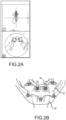
- FIG. 2A and 2B illustrate the virtually designing of the surgical guide and location and orientation of dental implant.
- the location of the dental implants is determined.
- the display includes a virtual representation of the patient's mouth, a virtual surgical guide and the axis 24 along with the dental implant is inserted into the virtual model.
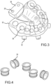
- a fabrication machine e.g., a rapid prototyping machine.
- a physical surgical guide 30 has been formed.
- the physical surgical guide 30 includes openings 26 that are configured to receive master tubes 34 ( FIG. 4 ), opening 32 that are configured to receive the fixation pins 13 ( FIG. 1 ), and a check booth attachment flange 36 including opening.
- a user would couple the master tubes 34 to the surgical guide 30.
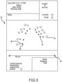
- a check protocol form 38 is also produced and sent to a traditional paper printer.
- the check protocol form 38 includes a calibration check points 40 that is configured to determine whether the dimensions of the check protocol form 38 are accurate.
- the form 38 further includes pointes 42 that correspond to the axis along which each implant is to be installed along and in relation to each other.
- the point 42 includes a center point 46 corresponding to the axis along which each implant is to be installed as well as a circle 48 surrounding the center point 36.
- the circle 48 defines the acceptable tolerance of the axis of the surgical guide. As discussed herein, during the checking procedure a pin must be within the circle 48 for that particular master tube to pass inspection.
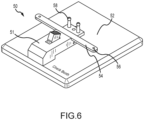
- FIG. 6 illustrates a check booth 50 that is configured to receive the form 38.
- the booth 50 includes a support surface 52 and a checking support 51 coupled to the support surface 52.
- the checking support 51 is moveable such that the support 52 can be lifted such that the form 38 can be inserted on the support surface 52 (see FIG. 7 ).
- the check support 51 can be biases towards the support surface 52 (e.g., a biasing member) such that pressure is placed on the form 38 thereby securing the form 38 to the booth 50.
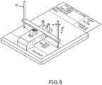
- the checking support 51 includes a calibration member 54 defining openings 56. As seen in FIG. 7 , the calibration member 54 and openings 56 align with the calibration check points 40 on the form 38.
- FIG. 8 illustrates calibration pins 60 inserted through the openings 56. As seen in FIG. 8 , the tip of the calibration pins 60 are within the calibration check points 40 thus confirming the dimensions of the form 38 are accurate.
- the check booth 50 further includes a support structure 55 to couple the physical surgical guide to the check booth 50.
- the support structure 55 includes openings 59 through which engagement pins 53 are inserted.
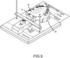
- FIG. 9 illustrates the physical surgical guide 30 including the master tubes 34 coupled to the check booth 50 via engagement pins 53 that extend through openings 28 of the surgical guide 30.
- FIG. 10 illustrates a plurality of check pins 62 extending through each master tube of the surgical guide.
- FIG. 11 illustrates a close-up a pin 62.
- a tip of the pin 62 is shown being positioned within the circle 48 of the point 42.
- a user can visually verify if the tip 62 is within the circle 48 of each point 42.
- the tip 62 can be configured to leave a mark on the form 50 thus a user can not only visually but also verify once the pins 62 are removed to see if the indentation or mark provided by the pin 62 is within the circle 48.
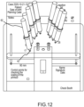
- FIG. 12 illustrates FIG. 11 without the surgical guide body 12 for simplicity.
- each pin 62 is within the point 42 corresponding to an axis of an implant in the surgical plan.
- the pins represent the axis formed by the master tubes.
- the axis of the pins 62 need to align within a certain tolerate of the axis of the implant in the surgical plan.
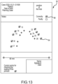
- FIG. 13 illustrates a completed check form 38 that includes accuracy check boxes 64 for each implant to be installed in a patient according to a surgical plan. If each check box 64 is marked for accuracy a final accuracy check box 66 can be marked. The physical surgical guide is now acceptable for use on a patient. If one of the pins does not align with the available tolerance, a user would select the faulty check box and a new surgical guide would need to be manufactured
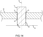
- FIG. 14 is a cross-section of a portion of the physical surgical guide 30 including the master tube 34.
- a scanning body 71 can be coupled to the master tube 34.
- Various scanning bodies are contemplated, and the scan body only need to be accurately coupled to the surgical guide such that a central axis of the master tube can be determined.
- sufficient seating of the scanning body 71 is necessary.
- a top surface 72 of the master tube is configured to engage with a seating surface 70 of the scanning body 71.
- some embodiments include placing the surgical guide on a scanning support 76 where the scanning support 76 can have a threaded opening 78 that can engage with a threaded surface of the scan body.
- the scan body 71 can be threaded into the scanning support 76 to securely hold the scanning body 71 to the surgical guide 30 for better accuracy.
- the surgical guide 30 including the scan bodies 71 are scanned.
- a virtual representation of the physical guide 30 including the scan bodies 71 can be determined.
- a user can modify the virtual representation such that an axis 74 of the master tubes 34 can be virtually depicted.
- the scan data illustrates the axis 74 of the master tubes 34 can be compared to the axis of the implant in the surgical plan and determine if they align.
- the present disclosure also includes a computer system that may be employed in accordance with at least some of the example embodiments herein.
- a computer system that may be employed in accordance with at least some of the example embodiments herein.
- the computer system may include a scanner such as CBCT, MRI and/or intra-oral scanner for obtaining 3D images of the dental cavity.
- the computer system may also include at least one computer processor.
- the computer system may be configured to receive the 3D images and the processor may be configured to analyze said 3D images in order to create the rendering of the patient which may be displayed on a display of the computer system.
- the computer system may take input from a clinician through an input unit such as a keyboard, mouse, touchscreen monitor or the like in order to create the surgical plan.
- a display interface may forward video graphics, text, and other data from the communication infrastructure (or from a frame buffer (not shown)) for display on the display unit.
- One or more steps of creating the surgical plan and checking the accuracy of the physical surgical guide may be stored on a non-transitory storage device in the form of computer-readable program instructions.
- the processor loads the appropriate instructions, as stored on the storage device, into memory, and then executes the loaded instructions.
- the computer system may also comprise a main memory, which may be a random-access memory ("RAM"), and also may include a secondary memory.
- the secondary memory may include, for example, a hard disk drive and/or a removable-storage drive (e.g., a floppy disk drive, a magnetic tape drive, an optical disk drive, a flash memory drive, and the like).
- the removable-storage drive may read from and/or write to a removable storage unit 140 in a well-known manner.
- the removable storage unit may be, for example, a floppy disk, a magnetic tape, an optical disk, a flash memory device, and the like, which may be written to and read from by the removable-storage drive.
- the removable storage unit may include a non-transitory computer-readable storage medium storing computer-executable software instructions and/or data.
- the secondary memory may include other computer-readable media storing computer-executable programs or other instructions to be loaded into the computer system.
- Such devices may include a removable storage unit and an interface (e.g., a program cartridge and a cartridge interface); a removable memory chip and an associated memory socket; and other removable storage units and interfaces that allow software and data to be transferred from the removable storage unit to other parts of the computer system.
- the computer system also may include a communications interface that enables software and data to be transferred between the computer system and external devices.
- Software and data transferred via the communications interface may be in the form of signals, which may be electronic, electromagnetic, optical or another type of signal that may be capable of being transmitted and/or received by the communications interface.
- Signals may be provided to the communications interface via a communications path (e.g., a channel).
- the communications path may carry signals and may be implemented using wire or cable, fiber optics, a telephone line, a cellular link, a radio-frequency ("RF") link, or the like.
- the communications interface may be used to transfer software or data or other information between the computer system and a remote server or cloud-based storage (not shown).
- One or more computer programs or computer control logic may be stored in the main memory and/or the secondary memory.
- the computer programs may also be received via the communications interface.
- the computer programs may include computer-executable instructions which, when executed by the computer processor, cause the computer system to perform the methods described. Accordingly, the computer programs may control the computer system.
- the software may be stored in a non-transitory computer-readable storage medium and loaded into the main memory and/or the secondary memory of the computer system using the removable-storage drive , the hard disk drive, and/or the communications interface .
- Control logic when executed by the processor, may cause the computer system, to perform all or some of the methods described herein.
Landscapes
- Health & Medical Sciences (AREA)
- Life Sciences & Earth Sciences (AREA)
- Oral & Maxillofacial Surgery (AREA)
- Public Health (AREA)
- Animal Behavior & Ethology (AREA)
- General Health & Medical Sciences (AREA)
- Veterinary Medicine (AREA)
- Dentistry (AREA)
- Epidemiology (AREA)
- Surgery (AREA)
- Biomedical Technology (AREA)
- Engineering & Computer Science (AREA)
- Nuclear Medicine, Radiotherapy & Molecular Imaging (AREA)
- Pathology (AREA)
- Biophysics (AREA)
- Heart & Thoracic Surgery (AREA)
- Medical Informatics (AREA)
- Molecular Biology (AREA)
- Orthopedic Medicine & Surgery (AREA)
- Dental Prosthetics (AREA)
Claims (5)
- System mit Kontrollblock (50) zur Verwendung bei der Bestimmung der Genauigkeit einer physischen chirurgischen Führung (30), die auf der Grundlage eines virtuellen chirurgischen Plans hergestellt wurde, der wenigstens ein virtuelles Implantat und eine virtuelle chirurgische Führung mit wenigstens einem Master-Rohr (34) enthält, wobei der Kontrollblock (50) Folgendes aufweist:eine Auflagefläche (52); undeine Kontrollstütze (51), die mit der Auflagefläche (52) gekoppelt ist,wobei die Auflagefläche (52) so gestaltet ist, dass sie ein Prüfprotokollformular (38) aufnehmen kann, undwobei die Kontrollstütze (51) ein Kalibrierungselement (54) aufweist, das Öffnungen (56) und eine Stützstruktur (55) aufweist, die so konfiguriert ist, dass sie mit der physischen chirurgischen Führung (30) in Eingriff kommen kann.
- System nach Anspruch 1, wobei das System ferner Folgendes aufweist:
eine Mehrzahl von Kalibrierungsstiften (60), die sich von einem ersten Ende bis zu einer Spitze erstrecken, wobei der Durchmesser der Kalibrierungsstifte (60) dem Durchmesser der Öffnungen (56) des Kalibrierungselements (54) entspricht. - System nach einem der vorhergehenden Ansprüche, wobei das System ferner Folgendes aufweist:
eine Mehrzahl von Kontrollstiften (62), die sich von einem ersten Ende bis zu einer Spitze erstrecken, wobei wenigstens ein erster Kontrollstift (62) der Mehrzahl von Kontrollstiften (62) einen ersten Durchmesser aufweist, der sich von einem Durchmesser eines zweiten Kontrollstifts (62) der Mehrzahl von Kontrollstiften (62) unterscheidet. - System nach einem der vorhergehenden Ansprüche, wobei das System ferner Folgendes aufweist:
eine Mehrzahl von Kontrollstiften (62), die dahingehend verwendet werden können, dass sie sich durch eine Mehrzahl von Master-Rohren (34) erstrecken können, die unterschiedliche Durchmesser aufweisen. - System nach einem der vorhergehenden Ansprüche, wobei das System ferner eine Mehrzahl von Kontrollstiften (62) aufweist, die sich von einem ersten Ende bis zu einer Spitze erstrecken, wobei die Spitze so konfiguriert ist, dass sie eine Markierung auf dem Prüfprotokollformular (38) hinterlässt.
Priority Applications (1)
| Application Number | Priority Date | Filing Date | Title |
|---|---|---|---|
| EP24209341.7A EP4483834A3 (de) | 2021-12-31 | 2022-12-29 | Chirurgische führungsprüfung |
Applications Claiming Priority (1)
| Application Number | Priority Date | Filing Date | Title |
|---|---|---|---|
| US202163295769P | 2021-12-31 | 2021-12-31 |
Related Child Applications (1)
| Application Number | Title | Priority Date | Filing Date |
|---|---|---|---|
| EP24209341.7A Division EP4483834A3 (de) | 2021-12-31 | 2022-12-29 | Chirurgische führungsprüfung |
Publications (3)
| Publication Number | Publication Date |
|---|---|
| EP4205698A1 EP4205698A1 (de) | 2023-07-05 |
| EP4205698C0 EP4205698C0 (de) | 2024-10-30 |
| EP4205698B1 true EP4205698B1 (de) | 2024-10-30 |
Family
ID=84688945
Family Applications (2)
| Application Number | Title | Priority Date | Filing Date |
|---|---|---|---|
| EP24209341.7A Pending EP4483834A3 (de) | 2021-12-31 | 2022-12-29 | Chirurgische führungsprüfung |
| EP22217106.8A Active EP4205698B1 (de) | 2021-12-31 | 2022-12-29 | Chirurgische führungsprüfung |
Family Applications Before (1)
| Application Number | Title | Priority Date | Filing Date |
|---|---|---|---|
| EP24209341.7A Pending EP4483834A3 (de) | 2021-12-31 | 2022-12-29 | Chirurgische führungsprüfung |
Country Status (2)
| Country | Link |
|---|---|
| US (1) | US20230210631A1 (de) |
| EP (2) | EP4483834A3 (de) |
Families Citing this family (2)
| Publication number | Priority date | Publication date | Assignee | Title |
|---|---|---|---|---|
| EP3870103A4 (de) * | 2018-10-23 | 2022-08-10 | Dentlytec G.P.L. Ltd. | Verfahren und vorrichtung zur überprüfung von zahnchirurgischen führungen |
| CN116785001B (zh) * | 2023-08-25 | 2023-10-31 | 深圳卡尔文科技有限公司 | 一种种植手术工具标定方法、系统和存储介质 |
Family Cites Families (16)
| Publication number | Priority date | Publication date | Assignee | Title |
|---|---|---|---|---|
| DE10309992A1 (de) * | 2003-02-28 | 2004-09-16 | Med3D Gmbh | Verfahren und Vorrichtung zur Kontrolle der Position von Bohrhülsen |
| ITTO20050542A1 (it) * | 2005-08-02 | 2007-02-03 | Alma Mater Studiorum Uni Di Bologna | Metodo e stazione di lavoro per realizzare una mascherina guida per la inserzione di un impianto osteointegrato nei mascellari |
| WO2009146195A1 (en) * | 2008-04-16 | 2009-12-03 | Biomet 3I, Llc | Method for pre-operative visualization of instrumentation used with a surgical guide for dental implant placement |
| US20100316974A1 (en) * | 2009-06-11 | 2010-12-16 | Pou Yu Biotechnology Co., Ltd. | Method of making a surgical template used for a computer-guided dental implant surgery |
| WO2011010177A1 (de) * | 2009-07-21 | 2011-01-27 | Schütz Dental Gmbh | Verfahren zur herstellung eines referenzierten digitalen datensatzes mindestens eines medizinischen bildes |
| DE102011003557B9 (de) * | 2011-02-03 | 2012-09-06 | Sirona Dental Systems Gmbh | Bohrschablone für ein dentales Implantat, ein Verfahren zur Herstellung dieser Bohrschablone sowie eine Vorrichtung zur Überprüfung der Bohrschablone und deren Verwendung |
| DE102011083439B4 (de) * | 2011-09-26 | 2017-06-29 | Sirona Dental Systems Gmbh | Verfahren zur Überprüfung einer Bohrschablone zur Herstellung eines implantatgestützten Zahnersatzes |
| ITTO20110966A1 (it) * | 2011-10-25 | 2013-04-26 | Roberto Villa | Metodo per prevedere l'effettivo posizionamento finale di un impianto destinato a essere impiantato in un paziente all'interno di un foro realizzato mediante uso di una dima chirurgica |
| US9801699B2 (en) * | 2013-03-14 | 2017-10-31 | Devin Okay | Paired templates for placing dental implants and enhancing registration for denture prosthetics attached to the implants |
| US9707061B2 (en) * | 2013-12-27 | 2017-07-18 | James R. Glidewell Dental Ceramics, Inc. | Apparatus and methods of making denture devices |
| US20150359479A1 (en) * | 2014-04-01 | 2015-12-17 | FPJ Enterprises, LLC | Methods for Obtaining Information Relative to a Specific Linear Trajectory |
| DE102016004641A1 (de) * | 2016-04-20 | 2017-10-26 | Axel Scheffer | Verfahren und System zur Erfassung der Ausrichtung von wenigstens einer Bohrhülse in einer für die lagerichtige Implantation von Zahnimplantaten hergestellten Bohrschablone |
| US10311126B2 (en) | 2016-08-12 | 2019-06-04 | International Business Machines Corporation | Memory device for matrix-vector multiplications |
| EP3870103A4 (de) * | 2018-10-23 | 2022-08-10 | Dentlytec G.P.L. Ltd. | Verfahren und vorrichtung zur überprüfung von zahnchirurgischen führungen |
| US11284967B2 (en) * | 2018-11-08 | 2022-03-29 | Swissmeda Ag | Bone foundation guide system with reduction guide |
| US11612462B2 (en) * | 2020-08-24 | 2023-03-28 | Dio Corporation | Method of implanting dental restoration |
-
2022
- 2022-12-29 EP EP24209341.7A patent/EP4483834A3/de active Pending
- 2022-12-29 US US18/091,093 patent/US20230210631A1/en active Pending
- 2022-12-29 EP EP22217106.8A patent/EP4205698B1/de active Active
Also Published As
| Publication number | Publication date |
|---|---|
| US20230210631A1 (en) | 2023-07-06 |
| EP4205698C0 (de) | 2024-10-30 |
| EP4483834A2 (de) | 2025-01-01 |
| EP4483834A3 (de) | 2025-01-22 |
| EP4205698A1 (de) | 2023-07-05 |
Similar Documents
| Publication | Publication Date | Title |
|---|---|---|
| US11992355B2 (en) | Method, apparatus, and computer program for planning implant surgery | |
| US12207980B2 (en) | Dental models for dental implant and related procedures | |
| US9585730B2 (en) | Dental implant insertion set and manufacturing method thereof | |
| EP3975919B1 (de) | Scanfähige heilkomponenten | |
| JP4621210B2 (ja) | 歯科用ブリッジ構造の作製および挿入のためのシステムおよび構成配置 | |
| JP4664274B2 (ja) | 歯科上部構造を配置および製造するための方法、インプラントを配置するための方法、およびこれが用いる付属物 | |
| US9801699B2 (en) | Paired templates for placing dental implants and enhancing registration for denture prosthetics attached to the implants | |
| JP5383659B2 (ja) | ステント | |
| EP4205698B1 (de) | Chirurgische führungsprüfung | |
| KR20200109273A (ko) | 치아 보철 제조를 위한 3차원 스캔 데이터 처리 방법 | |
| Dulla et al. | Influence of alveolar ridge morphology and guide-hole design on the accuracy of static Computer-Assisted Implant Surgery with two implant macro-designs: an in vitro study | |
| KR20110074186A (ko) | 보철물을 설계하는 방법 | |
| KR101134062B1 (ko) | 임플란트 어버트먼트를 만드는 방법 | |
| KR20190074098A (ko) | 치과용 임플란트 시술 가이드장치, 치과용 임플란트 시술 가이드장치 제작시스템 및 그 제작방법 | |
| US20220036996A1 (en) | Computer implemented method of planning a restorative dental treatment | |
| KR20130084800A (ko) | 임플란트 어버트먼트를 만드는 방법 | |
| Ballesteros et al. | A Comparative Study on the Accuracy of Implant Placement Using 3D‐Printed and Milled Guides Without Metal Sleeves | |
| Thomas | Three-Dimensional Accuracy of Implant Placement Related to the Use of Guide Sleeves | |
| IT201900016676A1 (it) | Metodo per produrre un kit implanto-protesico odontoiatrico |
Legal Events
| Date | Code | Title | Description |
|---|---|---|---|
| PUAI | Public reference made under article 153(3) epc to a published international application that has entered the european phase |
Free format text: ORIGINAL CODE: 0009012 |
|
| STAA | Information on the status of an ep patent application or granted ep patent |
Free format text: STATUS: REQUEST FOR EXAMINATION WAS MADE |
|
| 17P | Request for examination filed |
Effective date: 20221229 |
|
| AK | Designated contracting states |
Kind code of ref document: A1 Designated state(s): AL AT BE BG CH CY CZ DE DK EE ES FI FR GB GR HR HU IE IS IT LI LT LU LV MC ME MK MT NL NO PL PT RO RS SE SI SK SM TR |
|
| RBV | Designated contracting states (corrected) |
Designated state(s): AL AT BE BG CH CY CZ DE DK EE ES FI FR GB GR HR HU IE IS IT LI LT LU LV MC ME MK MT NL NO PL PT RO RS SE SI SK SM TR |
|
| GRAP | Despatch of communication of intention to grant a patent |
Free format text: ORIGINAL CODE: EPIDOSNIGR1 |
|
| STAA | Information on the status of an ep patent application or granted ep patent |
Free format text: STATUS: GRANT OF PATENT IS INTENDED |
|
| INTG | Intention to grant announced |
Effective date: 20240613 |
|
| GRAS | Grant fee paid |
Free format text: ORIGINAL CODE: EPIDOSNIGR3 |
|
| GRAA | (expected) grant |
Free format text: ORIGINAL CODE: 0009210 |
|
| STAA | Information on the status of an ep patent application or granted ep patent |
Free format text: STATUS: THE PATENT HAS BEEN GRANTED |
|
| AK | Designated contracting states |
Kind code of ref document: B1 Designated state(s): AL AT BE BG CH CY CZ DE DK EE ES FI FR GB GR HR HU IE IS IT LI LT LU LV MC ME MK MT NL NO PL PT RO RS SE SI SK SM TR |
|
| REG | Reference to a national code |
Ref country code: GB Ref legal event code: FG4D |
|
| REG | Reference to a national code |
Ref country code: CH Ref legal event code: EP |
|
| REG | Reference to a national code |
Ref country code: DE Ref legal event code: R096 Ref document number: 602022007250 Country of ref document: DE |
|
| REG | Reference to a national code |
Ref country code: IE Ref legal event code: FG4D |
|
| U01 | Request for unitary effect filed |
Effective date: 20241202 |
|
| U07 | Unitary effect registered |
Designated state(s): AT BE BG DE DK EE FI FR IT LT LU LV MT NL PT RO SE SI Effective date: 20241211 |
|
| U1N | Appointed representative for the unitary patent procedure changed after the registration of the unitary effect |
Representative=s name: PLATZOEDER, MICHAEL CHRISTIAN; DE |
|
| U1N | Appointed representative for the unitary patent procedure changed after the registration of the unitary effect |
Representative=s name: PLATZOEDER PATENTANWALTSGESELLSCHAFT MBH; DE |
|
| PG25 | Lapsed in a contracting state [announced via postgrant information from national office to epo] |
Ref country code: HR Free format text: LAPSE BECAUSE OF FAILURE TO SUBMIT A TRANSLATION OF THE DESCRIPTION OR TO PAY THE FEE WITHIN THE PRESCRIBED TIME-LIMIT Effective date: 20241030 Ref country code: IS Free format text: LAPSE BECAUSE OF FAILURE TO SUBMIT A TRANSLATION OF THE DESCRIPTION OR TO PAY THE FEE WITHIN THE PRESCRIBED TIME-LIMIT Effective date: 20250228 |
|
| PG25 | Lapsed in a contracting state [announced via postgrant information from national office to epo] |
Ref country code: ES Free format text: LAPSE BECAUSE OF FAILURE TO SUBMIT A TRANSLATION OF THE DESCRIPTION OR TO PAY THE FEE WITHIN THE PRESCRIBED TIME-LIMIT Effective date: 20241030 |
|
| PG25 | Lapsed in a contracting state [announced via postgrant information from national office to epo] |
Ref country code: NO Free format text: LAPSE BECAUSE OF FAILURE TO SUBMIT A TRANSLATION OF THE DESCRIPTION OR TO PAY THE FEE WITHIN THE PRESCRIBED TIME-LIMIT Effective date: 20250130 |
|
| PG25 | Lapsed in a contracting state [announced via postgrant information from national office to epo] |
Ref country code: GR Free format text: LAPSE BECAUSE OF FAILURE TO SUBMIT A TRANSLATION OF THE DESCRIPTION OR TO PAY THE FEE WITHIN THE PRESCRIBED TIME-LIMIT Effective date: 20250131 |
|
| PG25 | Lapsed in a contracting state [announced via postgrant information from national office to epo] |
Ref country code: PL Free format text: LAPSE BECAUSE OF FAILURE TO SUBMIT A TRANSLATION OF THE DESCRIPTION OR TO PAY THE FEE WITHIN THE PRESCRIBED TIME-LIMIT Effective date: 20241030 |
|
| PG25 | Lapsed in a contracting state [announced via postgrant information from national office to epo] |
Ref country code: RS Free format text: LAPSE BECAUSE OF FAILURE TO SUBMIT A TRANSLATION OF THE DESCRIPTION OR TO PAY THE FEE WITHIN THE PRESCRIBED TIME-LIMIT Effective date: 20250130 |
|
| PG25 | Lapsed in a contracting state [announced via postgrant information from national office to epo] |
Ref country code: SM Free format text: LAPSE BECAUSE OF FAILURE TO SUBMIT A TRANSLATION OF THE DESCRIPTION OR TO PAY THE FEE WITHIN THE PRESCRIBED TIME-LIMIT Effective date: 20241030 |
|
| PG25 | Lapsed in a contracting state [announced via postgrant information from national office to epo] |
Ref country code: MC Free format text: LAPSE BECAUSE OF FAILURE TO SUBMIT A TRANSLATION OF THE DESCRIPTION OR TO PAY THE FEE WITHIN THE PRESCRIBED TIME-LIMIT Effective date: 20241030 |
|
| PG25 | Lapsed in a contracting state [announced via postgrant information from national office to epo] |
Ref country code: SK Free format text: LAPSE BECAUSE OF FAILURE TO SUBMIT A TRANSLATION OF THE DESCRIPTION OR TO PAY THE FEE WITHIN THE PRESCRIBED TIME-LIMIT Effective date: 20241030 |
|
| PG25 | Lapsed in a contracting state [announced via postgrant information from national office to epo] |
Ref country code: CZ Free format text: LAPSE BECAUSE OF FAILURE TO SUBMIT A TRANSLATION OF THE DESCRIPTION OR TO PAY THE FEE WITHIN THE PRESCRIBED TIME-LIMIT Effective date: 20241030 |
|
| U90 | Renewal fees not paid: noting of loss of rights |
Free format text: RENEWAL FEE NOT PAID FOR YEAR 03 Effective date: 20250716 |
|
| PLBE | No opposition filed within time limit |
Free format text: ORIGINAL CODE: 0009261 |
|
| STAA | Information on the status of an ep patent application or granted ep patent |
Free format text: STATUS: NO OPPOSITION FILED WITHIN TIME LIMIT |
|
| 26N | No opposition filed |
Effective date: 20250731 |
|
| PG25 | Lapsed in a contracting state [announced via postgrant information from national office to epo] |
Ref country code: IE Free format text: LAPSE BECAUSE OF NON-PAYMENT OF DUE FEES Effective date: 20241229 |
|
| U93 | Unitary patent lapsed |
Free format text: RENEWAL FEE NOT PAID Effective date: 20241231 |