EP4205613A2 - Double whip stand mixer accessory - Google Patents
Double whip stand mixer accessory Download PDFInfo
- Publication number
- EP4205613A2 EP4205613A2 EP22211534.7A EP22211534A EP4205613A2 EP 4205613 A2 EP4205613 A2 EP 4205613A2 EP 22211534 A EP22211534 A EP 22211534A EP 4205613 A2 EP4205613 A2 EP 4205613A2
- Authority
- EP
- European Patent Office
- Prior art keywords
- whisk
- mixer
- drive shaft
- drive
- housing
- Prior art date
- Legal status (The legal status is an assumption and is not a legal conclusion. Google has not performed a legal analysis and makes no representation as to the accuracy of the status listed.)
- Withdrawn
Links
- 230000009977 dual effect Effects 0.000 claims abstract description 34
- 239000000470 constituent Substances 0.000 claims description 4
- 238000000034 method Methods 0.000 description 9
- 230000008901 benefit Effects 0.000 description 2
- 230000013011 mating Effects 0.000 description 2
- 230000008878 coupling Effects 0.000 description 1
- 238000010168 coupling process Methods 0.000 description 1
- 238000005859 coupling reaction Methods 0.000 description 1
- NJPPVKZQTLUDBO-UHFFFAOYSA-N novaluron Chemical compound C1=C(Cl)C(OC(F)(F)C(OC(F)(F)F)F)=CC=C1NC(=O)NC(=O)C1=C(F)C=CC=C1F NJPPVKZQTLUDBO-UHFFFAOYSA-N 0.000 description 1
- 238000000926 separation method Methods 0.000 description 1
Images



Classifications
-
- A—HUMAN NECESSITIES
- A47—FURNITURE; DOMESTIC ARTICLES OR APPLIANCES; COFFEE MILLS; SPICE MILLS; SUCTION CLEANERS IN GENERAL
- A47J—KITCHEN EQUIPMENT; COFFEE MILLS; SPICE MILLS; APPARATUS FOR MAKING BEVERAGES
- A47J43/00—Implements for preparing or holding food, not provided for in other groups of this subclass
- A47J43/04—Machines for domestic use not covered elsewhere, e.g. for grinding, mixing, stirring, kneading, emulsifying, whipping or beating foodstuffs, e.g. power-driven
- A47J43/044—Machines for domestic use not covered elsewhere, e.g. for grinding, mixing, stirring, kneading, emulsifying, whipping or beating foodstuffs, e.g. power-driven with tools driven from the top side
-
- A—HUMAN NECESSITIES
- A47—FURNITURE; DOMESTIC ARTICLES OR APPLIANCES; COFFEE MILLS; SPICE MILLS; SUCTION CLEANERS IN GENERAL
- A47J—KITCHEN EQUIPMENT; COFFEE MILLS; SPICE MILLS; APPARATUS FOR MAKING BEVERAGES
- A47J43/00—Implements for preparing or holding food, not provided for in other groups of this subclass
- A47J43/04—Machines for domestic use not covered elsewhere, e.g. for grinding, mixing, stirring, kneading, emulsifying, whipping or beating foodstuffs, e.g. power-driven
- A47J43/07—Parts or details, e.g. mixing tools, whipping tools
- A47J43/0705—Parts or details, e.g. mixing tools, whipping tools for machines with tools driven from the upper side
- A47J43/0711—Parts or details, e.g. mixing tools, whipping tools for machines with tools driven from the upper side mixing, whipping or cutting tools
-
- A—HUMAN NECESSITIES
- A47—FURNITURE; DOMESTIC ARTICLES OR APPLIANCES; COFFEE MILLS; SPICE MILLS; SUCTION CLEANERS IN GENERAL
- A47J—KITCHEN EQUIPMENT; COFFEE MILLS; SPICE MILLS; APPARATUS FOR MAKING BEVERAGES
- A47J43/00—Implements for preparing or holding food, not provided for in other groups of this subclass
- A47J43/04—Machines for domestic use not covered elsewhere, e.g. for grinding, mixing, stirring, kneading, emulsifying, whipping or beating foodstuffs, e.g. power-driven
- A47J43/07—Parts or details, e.g. mixing tools, whipping tools
- A47J43/08—Driving mechanisms
- A47J43/082—Driving mechanisms for machines with tools driven from the upper side
-
- B—PERFORMING OPERATIONS; TRANSPORTING
- B01—PHYSICAL OR CHEMICAL PROCESSES OR APPARATUS IN GENERAL
- B01F—MIXING, e.g. DISSOLVING, EMULSIFYING OR DISPERSING
- B01F27/00—Mixers with rotary stirring devices in fixed receptacles; Kneaders
- B01F27/80—Mixers with rotary stirring devices in fixed receptacles; Kneaders with stirrers rotating about a substantially vertical axis
- B01F27/805—Mixers with rotary stirring devices in fixed receptacles; Kneaders with stirrers rotating about a substantially vertical axis wherein the stirrers or the receptacles are moved in order to bring them into operative position; Means for fixing the receptacle
- B01F27/807—Mixers with rotary stirring devices in fixed receptacles; Kneaders with stirrers rotating about a substantially vertical axis wherein the stirrers or the receptacles are moved in order to bring them into operative position; Means for fixing the receptacle with the stirrer-head pivoting about a horizontal axis to bring it in and out of operative position, e.g. with receptacles pivoting about a horizontal axis for emptying
-
- B—PERFORMING OPERATIONS; TRANSPORTING
- B01—PHYSICAL OR CHEMICAL PROCESSES OR APPARATUS IN GENERAL
- B01F—MIXING, e.g. DISSOLVING, EMULSIFYING OR DISPERSING
- B01F27/00—Mixers with rotary stirring devices in fixed receptacles; Kneaders
- B01F27/80—Mixers with rotary stirring devices in fixed receptacles; Kneaders with stirrers rotating about a substantially vertical axis
- B01F27/95—Mixers with rotary stirring devices in fixed receptacles; Kneaders with stirrers rotating about a substantially vertical axis with stirrers having planetary motion, i.e. rotating about their own axis and about a sun axis
-
- B—PERFORMING OPERATIONS; TRANSPORTING
- B01—PHYSICAL OR CHEMICAL PROCESSES OR APPARATUS IN GENERAL
- B01F—MIXING, e.g. DISSOLVING, EMULSIFYING OR DISPERSING
- B01F27/00—Mixers with rotary stirring devices in fixed receptacles; Kneaders
- B01F27/80—Mixers with rotary stirring devices in fixed receptacles; Kneaders with stirrers rotating about a substantially vertical axis
- B01F27/96—Mixers with rotary stirring devices in fixed receptacles; Kneaders with stirrers rotating about a substantially vertical axis with openwork frames or cages
-
- A—HUMAN NECESSITIES
- A47—FURNITURE; DOMESTIC ARTICLES OR APPLIANCES; COFFEE MILLS; SPICE MILLS; SUCTION CLEANERS IN GENERAL
- A47J—KITCHEN EQUIPMENT; COFFEE MILLS; SPICE MILLS; APPARATUS FOR MAKING BEVERAGES
- A47J43/00—Implements for preparing or holding food, not provided for in other groups of this subclass
- A47J43/04—Machines for domestic use not covered elsewhere, e.g. for grinding, mixing, stirring, kneading, emulsifying, whipping or beating foodstuffs, e.g. power-driven
- A47J43/044—Machines for domestic use not covered elsewhere, e.g. for grinding, mixing, stirring, kneading, emulsifying, whipping or beating foodstuffs, e.g. power-driven with tools driven from the top side
- A47J2043/04454—Apparatus of counter top type
Definitions
- the present disclosure generally relates to a beater attachment for a stand mixer, and, more particularly, to a dual whisk beater attachment including a first whisk and a second whisk operably coupled to the first whisk via a plurality of operably coupled gears, wherein the first whisk is configured to rotate about a first offset rotational axis of the drive shaft and orbit a central axis of a mixing area and the second whisk is configured to rotate about a second rotational axis and rotate about the central axis.
- the mixer includes an eccentric drive mounted on a mixing head of the mixer and configured to orbit around a central axis of a mixing area and rotate an offset rotational axis of a drive shaft about the central axis of the mixing area.
- a dual whisk beater attachment may be operably coupled with the mixer and includes a housing operably coupled to the eccentric drive, a first whisk rotatably mounted within the housing and operably coupled to the drive shaft of the eccentric drive of the mixer, and a second whisk rotatably mounted within the housing and operably coupled to the drive shaft of the eccentric drive of the mixer via a plurality of gears disposed within the housing.
- the first whisk is configured to rotate about a first whisk rotational axis and orbit the central axis of the mixing area
- the second whisk is configured to rotate about a second whisk rotational axis.
- Additional features of this aspect may include the drive shaft being coupled with an electric motor disposed within the mixing head, wherein the drive shaft is received within the housing by which the housing is coupled to the eccentric drive.
- the mixer may include a mixing head to which the eccentric drive is coupled, and wherein the electric motor is disposed within the mixing head.
- the housing may be rotationally and operably coupled to an attachment drive lug disposed on the eccentric drive.
- the offset rotational axis of the drive shaft and the first whisk rotational axis may be coincident and the first whisk may be configured to rotate about the offset rotational axis of the drive shaft and orbit the central axis of a mixing area.
- the first whisk may be operably coupled to the drive shaft of the mixer by a releasable connector rotatably mounted in the housing.
- the releasable connector may directly and coaxially couple the drive shaft with the first whisk and the plurality of gears disposed within the housing may comprise a drive gear and a second whisk driven gear, the drive gear being disposed on the releasable connector such the drive shaft and the drive gear are axially coincident.
- the plurality of gears may drive the first whisk and the second whisk via a 1:1 gear ratio.
- the first whisk rotational axis may be offset from the offset rotational axis of the drive shaft and orbit the central axis of the mixing area along a first orbit path and the second whisk rotational axis may be offset from the central axis and orbit the central axis of the mixing area along a second orbit path.
- the housing may be operably coupled to the drive shaft of the eccentric drive by a magnet disposed in the housing.
- the first whisk rotational axis may be offset from the offset rotational axis of the drive shaft and orbit a central axis of a mixing area along a first orbit path and the second whisk rotational axis may be offset from the central axis and orbits the central axis along a second orbit path.
- the gears disposed within the housing may comprise a drive gear, a first whisk driven gear, a second whisk driven gear, and an idler gear operably coupled with the drive gear and one of either the first whisk driven gear or the second whisk driven gear.
- the drive gear may be directly coupled with and coaxially aligned with the drive shaft via the releasable connector
- the first whisk driven gear may be directly coupled with and coaxially aligned with the first whisk
- the second whisk driven gear may be directly coupled with and coaxially aligned with the second whisk.
- the first whisk may comprise a first plurality of whips and the second whisk comprises a second plurality of whips and the first plurality of whips and the second plurality of whips rotate out of phase, such that contact between the first plurality of whips and the second plurality of whips is avoided, and the first whisk and second whisk may rotate in opposite directions.
- An additional aspect of the present disclosure is a dual whisk beater attachment for a stand mixer, the dual whisk beater attachment comprising a housing operably coupled to an eccentric drive of the stand mixer.
- a first whisk is operably and axially coupled to a drive shaft of the stand mixer and a second whisk is operably coupled to the first whisk via a plurality of operably coupled gears disposed in the housing.
- the first whisk is configured to rotate about a first offset rotational axis of the drive shaft and orbit a central axis of a mixing area and the second whisk is configured to rotate about a second rotational axis and rotate about the central axis.
- Additional features of this aspect may include the first whisk having a first plurality of whips and the second whisk having a second plurality of whips, where the first plurality of whips and the second plurality of whips are out of phase such that contact between the first plurality of whips and the second plurality of whips is avoided; and the first whisk and second whisk rotate in opposite directions.
- the first whisk may be configured to rotate about a first rotational axis offset from the drive shaft and orbit a central axis of a mixing area along a first orbit path and the second whisk may be configured to rotate about a second rotational axis offset from the central axis and orbit the central axis along a second orbit path.
- a further aspect of the present disclosure is a dual whisk beater attachment for a stand mixer, the dual whisk beater attachment comprising a first whisk operably coupled to a drive shaft of the stand mixer, a second whisk operably coupled to the drive shaft of the stand mixer; and a plurality of gears by which the first whisk and the second whisk are operably coupled to the drive shaft of the stand mixer.
- the first whisk is configured to rotate about a first rotational axis offset from the drive shaft and orbit a central axis of a mixing area along a first orbit path and the second whisk is configured to rotate about a second rotational axis offset from the central axis and orbit the central axis along a second orbit path.
- Additional features of this aspect may include the plurality of gears being disposed within the housing and further comprising a drive gear, a first whisk driven gear, a second whisk driven gear, and an idler gear operably coupled with the drive gear and the second whisk driven gear.
- the first whisk may comprise a first plurality of whips and the second whisk may comprise a second plurality of whips, where the first plurality of whips and the second plurality of whips rotate out of phase, such that contact between the first plurality of whips and the second plurality of whips is avoided, the first whisk and second whisk rotate in opposite directions
- the first plurality of whips comprises four symmetrically situated whips having a first vertical length and a first transverse width
- the second plurality of whips comprises three symmetrically situated whips having a second vertical length and a second transverse width, such that the first vertical length of the first plurality of whips is less than the second vertical length of the second plurality of whips and the first transverse width of the first plurality of whips is greater than the second trans
- the terms “upper,” “lower,” “right,” “left,” “rear,” “front,” “vertical,” “horizontal,” and derivatives thereof shall relate to the disclosure as oriented in FIG. 1 .
- the term “front” shall refer to the surface of the element closer to an intended viewer, and the term “rear” shall refer to the surface of the element further from the intended viewer.
- the disclosure may assume various alternative orientations, except where expressly specified to the contrary.
- the specific devices and processes illustrated in the attached drawings, and described in the following specification are simply exemplary embodiments of the inventive concepts defined in the appended claims. Hence, specific dimensions and other physical characteristics relating to the embodiments disclosed herein are not to be considered as limiting, unless the claims expressly state otherwise.
- a stand mixer 10 includes a pedestal 12 and a mixing head 14.
- An electric motor 16 may is disposed within the mixing head 14 and may be configured to drive a drive shaft 18, as shown in FIG. 4 .
- the drive shaft 18 may be mounted to an eccentric drive 20 disposed on a forward bottom portion 22 of the mixing head 14.
- the eccentric drive 20 mounted on the mixing head 14 of the mixer 10 is also coupled with the electric motor 16 disposed within the mixing head 14 and may be configured to rotate around a central axis c of a mixing area m .
- the mixing area m generally coincides with area below a receptacle 64, such as a mixing bowl, within which the food constituents are mixed or combined into a homogeneous mass.
- the drive shaft 18, which may be offset from the central axis c , may be configured to rotate about a rotational axis r and orbit around the central axis c of the mixing area m as the eccentric drive 20 is rotated about the central axis c of the mixing area m .
- a dual whisk beater attachment 24 may be coupled to the mixing head 14 and employed to mix or combine food constituents into a homogeneous mass.
- the dual whisk beater attachment 24 includes a housing 26 that is operably coupled to the mixing head 14. More particularly, an upper portion 28 of the housing 26 of the dual whisk beater attachment 24 may be operably coupled to the eccentric drive 20 by the drive shaft 18, which is received within the housing 26.
- the housing 26 may also be rotationally and operably coupled to an attachment drive lug 30 disposed on the eccentric drive 20, which is adapted to engage a mating recess 32 in the housing 26 and thereby rotate the housing 26 and the dual whisk beater attachment 24 around the central axis c of the mixing area m .
- the dual whisk beater attachment 24 also includes a first whisk 34 rotatably mounted within the housing 26 and operably coupled to the drive shaft 18 of the eccentric drive 20 of the mixer 10.
- a second whisk 36 may be rotatably mounted within the housing 26 and operably coupled to the drive shaft 18 of the eccentric drive 20 of the mixer 10 via a plurality of gears, in particular, a first drive gear 38 and second driven gear 40, disclosed further below, disposed within the housing 26, as shown in FIG. 5 .
- the first whisk 34 is configured to rotate about a first whisk rotational axis and orbit the central axis c of a mixing area.
- the second whisk 36 is configured to rotate about a second whisk rotational axis.
- the drive shaft 18 extends into the housing 26 and is received within a releasable connector 42 rotatably disposed in the housing 26.
- the releasable connector 42 operably couples the drive shaft 18 to the first whisk 34 and, by doing so, operably couples the drive shaft 18 to the housing 26.
- the releasable connector 42 cooperates with a tab 44 and spring 46 mounted on the drive shaft 18, as may be seen in FIG. 4 , where the tab 44 may engage a recess 48 on the releasable connector 42 to releasably couple the drive shaft 18 to the releasable connector 42, as is known.
- the drive shaft 18 drives rotation of the first whisk 34 about the rotational axis r . Additionally, as the drive shaft 18 orbits around the central axis c , the first whisk 34 also orbits around the central axis c of the mixing area m .
- the releasable connector 42 thus directly and coaxially couples the drive shaft 18 with the first whisk 34.
- the releasable connector 42 rotates with the drive shaft 18 and includes the first drive gear 38, shown in FIG. 5 , which also rotates with the drive shaft 18.
- the first drive gear 38 is disposed on the releasable connector 42 such that the drive shaft 18 and the first drive gear 38 are axially coincident.
- the first drive gear 38 drives rotation of the second driven gear 40, which is operably coupled to the second whisk 36 by a bearing sleeve 50.
- the bearing sleeve 50 may have an upper bearing 52 and a lower bearing 54 that are received within and supported by an upper bearing race 56 and a lower bearing race 58 to allow free rotation of the second whisk 36.
- the offset rotational axis of the drive shaft 18 and the rotational axis of the first whisk 34 are coincident and the first whisk 34 is configured to rotate about the offset rotational axis of the drive shaft 18.
- the first whisk 34 may comprise a first plurality of whips 60 and the second whisk 36 may comprise a second plurality of whips 62.
- the first plurality of whips 60 and the second plurality of whips 62 rotate out of phase, such that contact between the first plurality of whips 60 and the second plurality of whips 62 is avoided.
- the first whisk 34 may be rotated in a first direction, while the second whisk 36 may be rotated in a second opposing direction.
- each of the first plurality of whips 60, 62 may comprise four symmetrically situated whips having a vertical length and a transverse width.
- a first vertical length L1 of the first plurality of whips 60 is substantially the same as a second vertical length L2 of the second plurality of whips 62.
- a first transverse width W1 of the first plurality of whips 60 is greater than the second transverse width W2 of the second plurality of whips 62, which better accommodates a shape of the receptacle 64, such as a mixing bowl, in the mixing area m .
- the drive shaft 18 drives rotation of the first whisk 34 and, through the plurality of gears 38, 40, also drives rotation of the second whisk 36.
- the first whisk 34 disposed on the rotational axis r of the drive shaft 18 is also configured to orbit around the central axis c
- the second whisk 36 is disposed on and configured to rotate about the central axis c , without orbiting.
- the plurality of gears 38, 40 may be substantially identical and may drive the first whisk 34 and the second whisk 36 at substantially the same speed at a 1:1 gear ratio.
- a second embodiment of the dual whisk beater attachment 24 is illustrated, where like or similar elements are designated as above.
- the housing 26 receives the drive shaft 18, as described above, via the releasable connector 42 disposed in the housing 26, as discussed above.
- the drive shaft 18 has been removed from the eccentric drive 20 of the mixing head 14 and has been positioned in the housing 26 for illustrative purposes.
- the housing 26 may also be rotationally and operably coupled to the attachment drive lug 30 disposed on the eccentric drive 20, which is adapted to engage the mating recess 32 in the housing 26 and thereby rotate the housing 26 around the central axis c of the mixing area m .
- the housing 26 may be also operably coupled to the drive shaft 18 of the eccentric drive 20 by a magnet 66 disposed in the housing 26.
- the housing 26 includes the magnet 66, which engages the mixer 10 and assists in coupling the dual whisk beater attachment 24 to the mixer 10.
- the magnet 66 may be used in conjunction with or instead of the releasable connector 42.
- Both the first whisk 34 may be offset from the rotational axis r and the second whisk 36 may be offset from the central axis c .
- both the first whisk 34 and the second whisk 36 are configured to rotate and orbit.
- the positions of the first whisk 34 and the second whisk 36 are disposed different distances from the central axis c . Accordingly, the first whisk 34 rotates about a first rotational axis offset from the rotational axis r and travels along a first orbiting path.
- the second whisk 36 rotates about a second rotational axis offset from the central axis c and travels along a second orbiting path, which is different from the first orbiting path.
- the housing 26 may also include a plurality of gears 68, 70, 72, and 74 for driving the first whisk 34 and the second whisk 36, as perhaps best shown in FIG. 9 .
- the plurality of gears disposed within the housing 26 may include the drive gear 68 directly coupled with and coaxially aligned with the drive shaft 18 via the releasable connector 42.
- the first whisk driven gear 70 may be directly coupled with and coaxially aligned with the first whisk 34.
- the second whisk driven gear 72 may be directly coupled with and coaxially aligned with the second whisk 36.
- An idler gear 74 may be operably coupled with the drive gear 68 and one of either the first whisk driven gear 70 or the second whisk driven gear 72. As shown, the idler gear 74 is coupled with the second driven whisk gear 72.
- a window 76 may be provided in a side 78 of the housing 26 through which a knob 80 may be accessed.
- the knob 80 may be directly coupled with and coaxially aligned with the drive gear 68 and the releasable connector 42, which is in turn operably coupled with the drive shaft 18.
- the tab 44 may be disengaged from the recess 48 in the releasable connector 42 and the drive shaft 18 may be withdrawn from the housing 26.
- the first whisk 34 and the second whisk 36 have different configurations.
- the first whisk 34 comprises the first plurality of whips 60 and the second whisk 36 comprises the second plurality of whips 62.
- the first plurality of whips 60 comprises four symmetrically situated whips 60 having a first vertical length L1 and a first transverse width W1
- the second plurality of whips 62 comprises three symmetrically situated whips 62 having a second vertical length L2 and a second transverse width W2.
- the first vertical length L1 of the first plurality of whips 60 may be less than the second vertical length L2 of the second plurality of whips 62.
- the first transverse width W1 of the first plurality of whips 60 may be greater than the second transverse width W2 of the second plurality of whips 62. These configurations allow both the whisks 34, 36 to rotate proportionally and accommodate a shape of the receptacle 64 in the mixing area m .
- the first plurality of whips 60 and the second plurality of whips 62 may be adapted to rotate out of phase, such that contact between the first plurality of whips 60 and the second plurality of whips 62 is avoided. Also, the first whisk 34 and second whisk 36 rotate in opposite directions.
Landscapes
- Engineering & Computer Science (AREA)
- Mechanical Engineering (AREA)
- Food Science & Technology (AREA)
- Chemical & Material Sciences (AREA)
- Chemical Kinetics & Catalysis (AREA)
- Mixers Of The Rotary Stirring Type (AREA)
- Accessories For Mixers (AREA)
Abstract
Description
- The present disclosure generally relates to a beater attachment for a stand mixer, and, more particularly, to a dual whisk beater attachment including a first whisk and a second whisk operably coupled to the first whisk via a plurality of operably coupled gears, wherein the first whisk is configured to rotate about a first offset rotational axis of the drive shaft and orbit a central axis of a mixing area and the second whisk is configured to rotate about a second rotational axis and rotate about the central axis.
- One aspect of the present disclosure is a mixer for combining food constituents into a homogeneous mass. The mixer includes an eccentric drive mounted on a mixing head of the mixer and configured to orbit around a central axis of a mixing area and rotate an offset rotational axis of a drive shaft about the central axis of the mixing area. A dual whisk beater attachment may be operably coupled with the mixer and includes a housing operably coupled to the eccentric drive, a first whisk rotatably mounted within the housing and operably coupled to the drive shaft of the eccentric drive of the mixer, and a second whisk rotatably mounted within the housing and operably coupled to the drive shaft of the eccentric drive of the mixer via a plurality of gears disposed within the housing. The first whisk is configured to rotate about a first whisk rotational axis and orbit the central axis of the mixing area, and the second whisk is configured to rotate about a second whisk rotational axis.
- Additional features of this aspect may include the drive shaft being coupled with an electric motor disposed within the mixing head, wherein the drive shaft is received within the housing by which the housing is coupled to the eccentric drive. The mixer may include a mixing head to which the eccentric drive is coupled, and wherein the electric motor is disposed within the mixing head. The housing may be rotationally and operably coupled to an attachment drive lug disposed on the eccentric drive. The offset rotational axis of the drive shaft and the first whisk rotational axis may be coincident and the first whisk may be configured to rotate about the offset rotational axis of the drive shaft and orbit the central axis of a mixing area. The first whisk may be operably coupled to the drive shaft of the mixer by a releasable connector rotatably mounted in the housing. The releasable connector may directly and coaxially couple the drive shaft with the first whisk and the plurality of gears disposed within the housing may comprise a drive gear and a second whisk driven gear, the drive gear being disposed on the releasable connector such the drive shaft and the drive gear are axially coincident. The plurality of gears may drive the first whisk and the second whisk via a 1:1 gear ratio. The first whisk rotational axis may be offset from the offset rotational axis of the drive shaft and orbit the central axis of the mixing area along a first orbit path and the second whisk rotational axis may be offset from the central axis and orbit the central axis of the mixing area along a second orbit path. The housing may be operably coupled to the drive shaft of the eccentric drive by a magnet disposed in the housing. The first whisk rotational axis may be offset from the offset rotational axis of the drive shaft and orbit a central axis of a mixing area along a first orbit path and the second whisk rotational axis may be offset from the central axis and orbits the central axis along a second orbit path. The gears disposed within the housing may comprise a drive gear, a first whisk driven gear, a second whisk driven gear, and an idler gear operably coupled with the drive gear and one of either the first whisk driven gear or the second whisk driven gear. The drive gear may be directly coupled with and coaxially aligned with the drive shaft via the releasable connector, the first whisk driven gear may be directly coupled with and coaxially aligned with the first whisk, and the second whisk driven gear may be directly coupled with and coaxially aligned with the second whisk. The first whisk may comprise a first plurality of whips and the second whisk comprises a second plurality of whips and the first plurality of whips and the second plurality of whips rotate out of phase, such that contact between the first plurality of whips and the second plurality of whips is avoided, and the first whisk and second whisk may rotate in opposite directions.
- An additional aspect of the present disclosure is a dual whisk beater attachment for a stand mixer, the dual whisk beater attachment comprising a housing operably coupled to an eccentric drive of the stand mixer. A first whisk is operably and axially coupled to a drive shaft of the stand mixer and a second whisk is operably coupled to the first whisk via a plurality of operably coupled gears disposed in the housing. The first whisk is configured to rotate about a first offset rotational axis of the drive shaft and orbit a central axis of a mixing area and the second whisk is configured to rotate about a second rotational axis and rotate about the central axis.
- Additional features of this aspect may include the first whisk having a first plurality of whips and the second whisk having a second plurality of whips, where the first plurality of whips and the second plurality of whips are out of phase such that contact between the first plurality of whips and the second plurality of whips is avoided; and the first whisk and second whisk rotate in opposite directions. The first whisk may be configured to rotate about a first rotational axis offset from the drive shaft and orbit a central axis of a mixing area along a first orbit path and the second whisk may be configured to rotate about a second rotational axis offset from the central axis and orbit the central axis along a second orbit path.
- A further aspect of the present disclosure is a dual whisk beater attachment for a stand mixer, the dual whisk beater attachment comprising a first whisk operably coupled to a drive shaft of the stand mixer, a second whisk operably coupled to the drive shaft of the stand mixer; and a plurality of gears by which the first whisk and the second whisk are operably coupled to the drive shaft of the stand mixer. The first whisk is configured to rotate about a first rotational axis offset from the drive shaft and orbit a central axis of a mixing area along a first orbit path and the second whisk is configured to rotate about a second rotational axis offset from the central axis and orbit the central axis along a second orbit path.
- Additional features of this aspect may include the plurality of gears being disposed within the housing and further comprising a drive gear, a first whisk driven gear, a second whisk driven gear, and an idler gear operably coupled with the drive gear and the second whisk driven gear. The first whisk may comprise a first plurality of whips and the second whisk may comprise a second plurality of whips, where the first plurality of whips and the second plurality of whips rotate out of phase, such that contact between the first plurality of whips and the second plurality of whips is avoided, the first whisk and second whisk rotate in opposite directions, and the first plurality of whips comprises four symmetrically situated whips having a first vertical length and a first transverse width and the second plurality of whips comprises three symmetrically situated whips having a second vertical length and a second transverse width, such that the first vertical length of the first plurality of whips is less than the second vertical length of the second plurality of whips and the first transverse width of the first plurality of whips is greater than the second transverse width of the second plurality of whips.
- These and other features, advantages, and objects of the present disclosure will be further understood and appreciated by those skilled in the art by reference to the following specification, claims, and appended drawings.
- In the drawings:
-
FIG. 1 is a perspective view of a stand mixer to which is operably coupled a first embodiment of the dual whisk beater attachment according to the present disclosure disposed within a mixing bowl; -
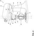
FIG. 2 is a perspective view of the stand mixer to which is operably coupled the first embodiment of the dual whisk beater attachment according to the present disclosure shown inFIG. 1 , with mixing bowl removed; -
FIG. 3 is a side view of the first embodiment of the dual whisk beater attachment according to the present disclosure shown inFIG. 1 ; -
FIG. 4 is a side view of the stand mixer to which may be operably coupled the first embodiment of the dual whisk beater attachment according to the present disclosure shown inFIG. 1 , with the dual whisk beater attachment removed; -
FIG. 5 is a side view of the first embodiment of the dual whisk beater attachment according to the present disclosure shown inFIG. 1 , with one side of the housing removed; -
FIG. 6 is a perspective view of a second embodiment of the dual whisk beater attachment according to the present disclosure; -
FIG. 7 is a top view of the second embodiment of the dual whisk beater attachment according to the present disclosure shown inFIG. 6 ; -
FIG. 8 is a side view of the second embodiment of the dual whisk beater attachment according to the present disclosure shown inFIG. 6 ; -
FIG. 9 is a cross-sectional view of the second embodiment of the dual whisk beater attachment according to the present disclosure shown inFIG. 6 , taken along the line IX-IX inFIG. 8 . - The components in the figures are not necessarily to scale, emphasis instead being placed upon illustrating the principles described herein.
- The present illustrated embodiments reside primarily in combinations of method steps and apparatus components related to a dual whisk beater attachment. Accordingly, the apparatus components and method steps have been represented, where appropriate, by conventional symbols in the drawings, showing only those specific details that are pertinent to understanding the embodiments of the present disclosure so as not to obscure the disclosure with details that will be readily apparent to those of ordinary skill in the art having the benefit of the description herein. Further, like numerals in the description and drawings represent like elements.
- For purposes of description herein, the terms "upper," "lower," "right," "left," "rear," "front," "vertical," "horizontal," and derivatives thereof shall relate to the disclosure as oriented in
FIG. 1 . Unless stated otherwise, the term "front" shall refer to the surface of the element closer to an intended viewer, and the term "rear" shall refer to the surface of the element further from the intended viewer. However, it is to be understood that the disclosure may assume various alternative orientations, except where expressly specified to the contrary. It is also to be understood that the specific devices and processes illustrated in the attached drawings, and described in the following specification are simply exemplary embodiments of the inventive concepts defined in the appended claims. Hence, specific dimensions and other physical characteristics relating to the embodiments disclosed herein are not to be considered as limiting, unless the claims expressly state otherwise. - The terms "including," "comprises," "comprising," or any other variation thereof, are intended to cover a non-exclusive inclusion, such that a process, method, article, or apparatus that comprises a list of elements does not include only those elements but may include other elements not expressly listed or inherent to such process, method, article, or apparatus. An element proceeded by "comprises a . . . " does not, without more constraints, preclude the existence of additional identical elements in the process, method, article, or apparatus that comprises the element.
- With reference to the
FIGS. 1-9 , astand mixer 10 includes apedestal 12 and amixing head 14. Anelectric motor 16 may is disposed within themixing head 14 and may be configured to drive adrive shaft 18, as shown inFIG. 4 . Thedrive shaft 18 may be mounted to aneccentric drive 20 disposed on aforward bottom portion 22 of themixing head 14. Theeccentric drive 20 mounted on themixing head 14 of themixer 10 is also coupled with theelectric motor 16 disposed within themixing head 14 and may be configured to rotate around a central axis c of a mixing area m. The mixing area m generally coincides with area below areceptacle 64, such as a mixing bowl, within which the food constituents are mixed or combined into a homogeneous mass. Thedrive shaft 18, which may be offset from the central axis c, may be configured to rotate about a rotational axis r and orbit around the central axis c of the mixing area m as theeccentric drive 20 is rotated about the central axis c of the mixing area m. - A dual
whisk beater attachment 24 may be coupled to the mixinghead 14 and employed to mix or combine food constituents into a homogeneous mass. The dualwhisk beater attachment 24 includes ahousing 26 that is operably coupled to themixing head 14. More particularly, anupper portion 28 of thehousing 26 of the dualwhisk beater attachment 24 may be operably coupled to theeccentric drive 20 by thedrive shaft 18, which is received within thehousing 26. Thehousing 26 may also be rotationally and operably coupled to anattachment drive lug 30 disposed on theeccentric drive 20, which is adapted to engage amating recess 32 in thehousing 26 and thereby rotate thehousing 26 and the dualwhisk beater attachment 24 around the central axis c of the mixing area m. - The dual
whisk beater attachment 24 also includes afirst whisk 34 rotatably mounted within thehousing 26 and operably coupled to thedrive shaft 18 of theeccentric drive 20 of themixer 10. Asecond whisk 36 may be rotatably mounted within thehousing 26 and operably coupled to thedrive shaft 18 of theeccentric drive 20 of themixer 10 via a plurality of gears, in particular, afirst drive gear 38 and second drivengear 40, disclosed further below, disposed within thehousing 26, as shown inFIG. 5 . Thefirst whisk 34 is configured to rotate about a first whisk rotational axis and orbit the central axis c of a mixing area. Thesecond whisk 36 is configured to rotate about a second whisk rotational axis. - In a first embodiment of the dual
whisk beater attachment 24, shown inFIGS. 1-5 , thedrive shaft 18 extends into thehousing 26 and is received within areleasable connector 42 rotatably disposed in thehousing 26. Thereleasable connector 42 operably couples thedrive shaft 18 to thefirst whisk 34 and, by doing so, operably couples thedrive shaft 18 to thehousing 26. Thereleasable connector 42 cooperates with atab 44 andspring 46 mounted on thedrive shaft 18, as may be seen inFIG. 4 , where thetab 44 may engage arecess 48 on thereleasable connector 42 to releasably couple thedrive shaft 18 to thereleasable connector 42, as is known. As thedrive shaft 18 rotates about the rotational axis r, thedrive shaft 18 drives rotation of thefirst whisk 34 about the rotational axis r. Additionally, as thedrive shaft 18 orbits around the central axis c, thefirst whisk 34 also orbits around the central axis c of the mixing area m. - The
releasable connector 42 thus directly and coaxially couples thedrive shaft 18 with thefirst whisk 34. Thereleasable connector 42 rotates with thedrive shaft 18 and includes thefirst drive gear 38, shown inFIG. 5 , which also rotates with thedrive shaft 18. Thefirst drive gear 38 is disposed on thereleasable connector 42 such that thedrive shaft 18 and thefirst drive gear 38 are axially coincident. Thefirst drive gear 38 drives rotation of the second drivengear 40, which is operably coupled to thesecond whisk 36 by a bearingsleeve 50. The bearingsleeve 50 may have anupper bearing 52 and alower bearing 54 that are received within and supported by an upper bearing race 56 and alower bearing race 58 to allow free rotation of thesecond whisk 36. The offset rotational axis of thedrive shaft 18 and the rotational axis of thefirst whisk 34 are coincident and thefirst whisk 34 is configured to rotate about the offset rotational axis of thedrive shaft 18. - The
first whisk 34 may comprise a first plurality ofwhips 60 and thesecond whisk 36 may comprise a second plurality ofwhips 62. The first plurality ofwhips 60 and the second plurality ofwhips 62 rotate out of phase, such that contact between the first plurality ofwhips 60 and the second plurality ofwhips 62 is avoided. Thefirst whisk 34 may be rotated in a first direction, while thesecond whisk 36 may be rotated in a second opposing direction. As shown inFIGS. 1-5 , each of the first plurality ofwhips whips 60 is substantially the same as a second vertical length L2 of the second plurality ofwhips 62. However, a first transverse width W1 of the first plurality ofwhips 60 is greater than the second transverse width W2 of the second plurality ofwhips 62, which better accommodates a shape of thereceptacle 64, such as a mixing bowl, in the mixing area m. - Accordingly, the
drive shaft 18 drives rotation of thefirst whisk 34 and, through the plurality ofgears second whisk 36. Thefirst whisk 34 disposed on the rotational axis r of thedrive shaft 18 is also configured to orbit around the central axis c, while thesecond whisk 36 is disposed on and configured to rotate about the central axis c, without orbiting. As shown inFIG. 5 , the plurality ofgears first whisk 34 and thesecond whisk 36 at substantially the same speed at a 1:1 gear ratio. - With reference to
FIGS. 6-9 , in addition to or as an alternative, a second embodiment of the dualwhisk beater attachment 24 is illustrated, where like or similar elements are designated as above. In this configuration, thehousing 26 receives thedrive shaft 18, as described above, via thereleasable connector 42 disposed in thehousing 26, as discussed above. As shown, thedrive shaft 18 has been removed from theeccentric drive 20 of the mixinghead 14 and has been positioned in thehousing 26 for illustrative purposes. In addition, thehousing 26 may also be rotationally and operably coupled to theattachment drive lug 30 disposed on theeccentric drive 20, which is adapted to engage themating recess 32 in thehousing 26 and thereby rotate thehousing 26 around the central axis c of the mixing area m. - However, in the configuration shown in
FIG. 6-9 , thehousing 26 may be also operably coupled to thedrive shaft 18 of theeccentric drive 20 by amagnet 66 disposed in thehousing 26. Thehousing 26 includes themagnet 66, which engages themixer 10 and assists in coupling the dualwhisk beater attachment 24 to themixer 10. Themagnet 66 may be used in conjunction with or instead of thereleasable connector 42. - Both the
first whisk 34 may be offset from the rotational axis r and thesecond whisk 36 may be offset from the central axis c. In this way, both thefirst whisk 34 and thesecond whisk 36 are configured to rotate and orbit. The positions of thefirst whisk 34 and thesecond whisk 36 are disposed different distances from the central axis c. Accordingly, thefirst whisk 34 rotates about a first rotational axis offset from the rotational axis r and travels along a first orbiting path. Thesecond whisk 36 rotates about a second rotational axis offset from the central axis c and travels along a second orbiting path, which is different from the first orbiting path. - The
housing 26 may also include a plurality ofgears first whisk 34 and thesecond whisk 36, as perhaps best shown inFIG. 9 . The plurality of gears disposed within thehousing 26 may include thedrive gear 68 directly coupled with and coaxially aligned with thedrive shaft 18 via thereleasable connector 42. The first whisk drivengear 70 may be directly coupled with and coaxially aligned with thefirst whisk 34. Likewise, the second whisk drivengear 72 may be directly coupled with and coaxially aligned with thesecond whisk 36. Anidler gear 74 may be operably coupled with thedrive gear 68 and one of either the first whisk drivengear 70 or the second whisk drivengear 72. As shown, theidler gear 74 is coupled with the second drivenwhisk gear 72. - To facilitate separation of the
drive shaft 18 from thehousing 26, and removal of the second embodiment of the dualwhisk beater attachment 24 from themixer 10, awindow 76 may be provided in aside 78 of thehousing 26 through which aknob 80 may be accessed. Theknob 80 may be directly coupled with and coaxially aligned with thedrive gear 68 and thereleasable connector 42, which is in turn operably coupled with thedrive shaft 18. By pushing up on theknob 80 and slightly rotating the same, thetab 44 may be disengaged from therecess 48 in thereleasable connector 42 and thedrive shaft 18 may be withdrawn from thehousing 26. - In the illustrated configuration, the
first whisk 34 and thesecond whisk 36 have different configurations. Thefirst whisk 34 comprises the first plurality ofwhips 60 and thesecond whisk 36 comprises the second plurality ofwhips 62. As shown, the first plurality ofwhips 60 comprises four symmetrically situated whips 60 having a first vertical length L1 and a first transverse width W1, while the second plurality ofwhips 62 comprises three symmetrically situated whips 62 having a second vertical length L2 and a second transverse width W2. The first vertical length L1 of the first plurality ofwhips 60 may be less than the second vertical length L2 of the second plurality ofwhips 62. The first transverse width W1 of the first plurality ofwhips 60 may be greater than the second transverse width W2 of the second plurality ofwhips 62. These configurations allow both thewhisks receptacle 64 in the mixing area m. - As in the first embodiment, the first plurality of
whips 60 and the second plurality ofwhips 62 may be adapted to rotate out of phase, such that contact between the first plurality ofwhips 60 and the second plurality ofwhips 62 is avoided. Also, thefirst whisk 34 andsecond whisk 36 rotate in opposite directions.
Claims (15)
- A mixer (10) for combining food constituents into a homogeneous mass, the mixer (10) comprising:an eccentric drive (20) mounted on a mixing head (14) of the mixer (10) and configured to orbit around a central axis (c) of a mixing area (m) and rotate an offset rotational axis of a drive shaft (18) about the central axis (c) of the mixing area (m); anda dual whisk beater attachment (24), the dual whisk beater attachment (24) further comprising:a housing (26) operably coupled to the eccentric drive (20);a first whisk (34) rotatably mounted within the housing (26) and operably coupled to the drive shaft of the eccentric drive (20) of the mixer (10); anda second whisk (36) rotatably mounted within the housing (26) and operably coupled to the drive shaft (18) of the eccentric drive (20) of the mixer (10) via a plurality of gears (38, 40, 68, 70, 72, 74) disposed within the housing (26);wherein the first whisk (34) is configured to rotate about a first whisk rotational axis and orbit the central axis of the mixing area (m); andwherein the second whisk (36) is configured to rotate about a second whisk rotational axis.
- The mixer (10) of claim 1, wherein the drive shaft (18) is coupled with an electric motor (16) disposed within the mixing head (14), and wherein the drive shaft (18) is received within the housing (26) by which the housing (26) is coupled to the eccentric drive (20).
- The mixer (10) of any of claims 1 and 2, wherein the mixer (10) includes a mixing head (14) to which the eccentric drive (20) is coupled, and wherein the electric motor (16) is disposed within the mixing head (14).
- The mixer (10) of any of claims 1 through 3, wherein the housing (26) is rotationally and operably coupled to an attachment drive lug (30) disposed on the eccentric drive (20).
- The mixer (10) of any of claims 1 through 4, wherein the offset rotational axis of the drive shaft (18) and the first whisk rotational axis are coincident and the first whisk (34) is configured to rotate about the offset rotational axis of the drive shaft (18) and orbit the central axis (c) of the mixing area (m).
- The mixer (10) of any of claims 1 through 5, wherein the first whisk (34) is operably coupled to the drive shaft (18) of the mixer (10) by a releasable connector rotatably (42) mounted in the housing (26).
- The mixer (10) of claim 6, wherein the releasable connector (42) directly and coaxially couples the drive shaft (18) with the first whisk (34) and the plurality of gears (38, 40) disposed within the housing (26) comprises a drive gear (38) and a second whisk driven gear (40), the drive gear (38) being disposed on the releasable connector (42) such the drive shaft (18) and the drive gear (38) are axially coincident.
- The mixer (10) of any of claims 1 through 7, wherein the plurality of gears (38, 40) drives the first whisk (34) and the second whisk (36) via a 1:1 gear ratio.
- The mixer (10) of any of claims 1 through 4, wherein the first whisk (34) rotational axis is offset from the offset rotational axis of the drive shaft (18) and orbits the central axis (c) of the mixing area (m) along a first orbit path and the second whisk (36) rotational axis is offset from the central axis (c) and orbits the central axis (c) of the mixing area (m) along a second orbit path.
- The mixer (10) of claims 1 through 4 and 9, wherein the plurality of gears (68, 70, 72, 74) disposed within the housing (26) comprises a drive gear (68), a first whisk driven gear (70), a second whisk driven gear (72), and an idler gear (74) operably coupled with the drive gear (68) and one of either the first whisk driven gear (70) or the second whisk driven gear (72).
- The mixer (10) of claims 1 through 4 and 9 through 10, wherein the drive gear (68) is directly coupled with and coaxially aligned with the drive shaft (18) via a releasable connector (42), the first whisk driven gear (70) is directly coupled with and coaxially aligned with the first whisk (34), and the second whisk driven gear (72) is directly coupled with and coaxially aligned with the second whisk (36).
- The mixer (10) of claims 1 through 11, wherein:the first whisk (34) comprises a first plurality of whips (60) and the second whisk (36) comprises a second plurality of whips (62);the first plurality of whips (60) and the second plurality of whips (62) rotate out of phase, such that contact between the first plurality of whips (60) and the second plurality of whips (62) is avoided; andthe first whisk (34) and the second whisk (36) rotate in opposite directions.
- A dual whisk beater attachment (24) for a stand mixer (10), the dual whisk beater attachment (24) comprising:a housing (26) operably coupled to an eccentric drive (20) of the stand mixer (10);a first whisk (34) operably and axially coupled to a drive shaft (18) of the stand mixer (10); anda second whisk (36) operably coupled to the first whisk (34) via a plurality of operably coupled gears (38, 40) disposed in the housing (26);wherein the first whisk (34) is configured to rotate about a first offset rotational axis of the drive shaft (18) and orbit a central axis (c) of a mixing area (m) and the second whisk (36) is configured to rotate about a second rotational axis and rotate about the central axis (c).
- A dual whisk beater attachment (24) for a stand mixer (10), the dual whisk beater attachment (24) comprising:a first whisk (34) operably coupled to a drive shaft (18) of the stand mixer (10);a second whisk (36) operably coupled to the drive shaft (18) of the stand mixer (10); anda plurality of gears (68, 70, 72, 74) by which the first whisk (34) and the second whisk (36) are operably coupled to the drive shaft (18) of the stand mixer (10);wherein the first whisk (34) is configured to rotate about a first rotational axis offset from the drive shaft (18) and orbit a central axis (c) of a mixing area (m) along a first orbit path and the second whisk (36) is configured to rotate about a second rotational axis offset from the central axis (c) and orbit the central axis (c) along a second orbit path.
- The dual whisk beater attachment of claim 14, wherein the plurality of gears (68, 70, 72, 74) are disposed within a housing (26) and further comprise a drive gear (68), a first whisk driven gear (70), a second whisk driven gear (72), and an idler gear (74) operably coupled with the drive gear (68) and the second whisk driven gear (72).
Applications Claiming Priority (1)
| Application Number | Priority Date | Filing Date | Title |
|---|---|---|---|
| US17/568,016 US12369752B2 (en) | 2022-01-04 | 2022-01-04 | Double whip stand mixer accessory |
Publications (2)
| Publication Number | Publication Date |
|---|---|
| EP4205613A2 true EP4205613A2 (en) | 2023-07-05 |
| EP4205613A3 EP4205613A3 (en) | 2023-08-30 |
Family
ID=84421112
Family Applications (1)
| Application Number | Title | Priority Date | Filing Date |
|---|---|---|---|
| EP22211534.7A Withdrawn EP4205613A3 (en) | 2022-01-04 | 2022-12-05 | Double whip stand mixer accessory |
Country Status (2)
| Country | Link |
|---|---|
| US (1) | US12369752B2 (en) |
| EP (1) | EP4205613A3 (en) |
Families Citing this family (2)
| Publication number | Priority date | Publication date | Assignee | Title |
|---|---|---|---|---|
| USD987373S1 (en) * | 2020-10-09 | 2023-05-30 | Spa Sled Mover, LLC | Stand-mixer slider |
| USD987374S1 (en) * | 2020-10-09 | 2023-05-30 | Spa Sled Mover, LLC | Stand-mixer slider |
Family Cites Families (16)
| Publication number | Priority date | Publication date | Assignee | Title |
|---|---|---|---|---|
| US4023780A (en) | 1975-09-03 | 1977-05-17 | Egid Eugene I | Method of mixing and apparatus therefor |
| US4176971A (en) | 1978-07-19 | 1979-12-04 | Sunbeam Corporation | Multi-purpose kitchen appliance |
| US5000578A (en) | 1990-03-02 | 1991-03-19 | Sunbeam Corporation | Food mixing appliance |
| EP1182955A1 (en) | 2000-03-15 | 2002-03-06 | Koninklijke Philips Electronics N.V. | Domestic kitchen appliance with transmission unit |
| US6652137B1 (en) | 2000-03-16 | 2003-11-25 | Charles Ross & Son Company | Stirrer for a planetary mixer and a planetary mixer incorporating the stirrer |
| DE102007011517A1 (en) | 2007-03-09 | 2008-09-11 | Braun Gmbh | Kitchen appliance for domestic use |
| GB2453546A (en) | 2007-10-08 | 2009-04-15 | Kenwood Ltd | Planetary drive system |
| WO2011144820A1 (en) | 2010-05-20 | 2011-11-24 | Seb S.A. | Electrical household mixer appliance for culinary preparation including two planetary motion whips |
| US8616763B2 (en) | 2010-10-05 | 2013-12-31 | Whirlpool Corporation | Stand mixer wiping beater with additional features |
| FR2971689B1 (en) | 2011-02-18 | 2014-02-21 | Seb Sa | WHIP FOR CULINARY PREPARATION ELECTRICAL APPLIANCE |
| GB2548082A (en) | 2016-02-24 | 2017-09-13 | Kenwood Ltd | Processing tool |
| EP3262999A1 (en) * | 2016-07-01 | 2018-01-03 | DKB Household UK Limited | A mixer |
| DE102016216108A1 (en) | 2016-08-26 | 2018-03-01 | BSH Hausgeräte GmbH | Gear unit for a food processor |
| CN206398016U (en) | 2017-01-18 | 2017-08-11 | 金学士 | A kind of cone planetary gears applied to cook's machine |
| CN210493818U (en) | 2019-05-31 | 2020-05-12 | 广东新宝电器股份有限公司 | Mixer |
| US20210282597A1 (en) * | 2020-03-12 | 2021-09-16 | King-Yuan Lin | Food mixer scraper and method of operation |
-
2022
- 2022-01-04 US US17/568,016 patent/US12369752B2/en active Active
- 2022-12-05 EP EP22211534.7A patent/EP4205613A3/en not_active Withdrawn
Also Published As
| Publication number | Publication date |
|---|---|
| EP4205613A3 (en) | 2023-08-30 |
| US20230210308A1 (en) | 2023-07-06 |
| US12369752B2 (en) | 2025-07-29 |
Similar Documents
| Publication | Publication Date | Title |
|---|---|---|
| EP4212236A2 (en) | Micro puree machine with fixed motors | |
| US11759057B1 (en) | Micro puree machine with angled bowl | |
| US6824303B2 (en) | Apparatus for blending and making ice cream | |
| US20230210308A1 (en) | Double whip stand mixer accessory | |
| EP4364622A2 (en) | Bowl assembly for a micro puree machine | |
| US7395751B2 (en) | Beverage-making appliance | |
| US20170224170A1 (en) | Anti-cavitation food blender or processor | |
| EP4205612A2 (en) | 3d beater | |
| CN107550325A (en) | Blender | |
| CN210699778U (en) | Coffee food compounding device | |
| JP3191494U (en) | Ice processing machine with stick | |
| CN103372388B (en) | Handheld electric mixer | |
| EP0156506A1 (en) | A food processing arrangement | |
| US12376605B2 (en) | Ice cream maker | |
| JP3757934B2 (en) | Soft ice beverage production equipment | |
| CN222171990U (en) | Double-end mixer | |
| CN220142655U (en) | Low-fat soybean protein isolate extraction device | |
| JP3722113B2 (en) | Soft ice beverage production equipment | |
| CN111685186A (en) | Processing device and modulation method of white kidney bean and blood orange milk shake | |
| CN218047548U (en) | Pie filling material mixer | |
| KR102534206B1 (en) | A whipping cream manufacture device | |
| JP3186892U (en) | Stirrer | |
| WO2022271845A1 (en) | Bowl assembly for a micro puree machine | |
| CN118805839A (en) | Ice cream machine | |
| GB2171023A (en) | Liquid beater for household mixers |
Legal Events
| Date | Code | Title | Description |
|---|---|---|---|
| PUAI | Public reference made under article 153(3) epc to a published international application that has entered the european phase |
Free format text: ORIGINAL CODE: 0009012 |
|
| STAA | Information on the status of an ep patent application or granted ep patent |
Free format text: STATUS: THE APPLICATION HAS BEEN PUBLISHED |
|
| AK | Designated contracting states |
Kind code of ref document: A2 Designated state(s): AL AT BE BG CH CY CZ DE DK EE ES FI FR GB GR HR HU IE IS IT LI LT LU LV MC ME MK MT NL NO PL PT RO RS SE SI SK SM TR |
|
| PUAL | Search report despatched |
Free format text: ORIGINAL CODE: 0009013 |
|
| AK | Designated contracting states |
Kind code of ref document: A3 Designated state(s): AL AT BE BG CH CY CZ DE DK EE ES FI FR GB GR HR HU IE IS IT LI LT LU LV MC ME MK MT NL NO PL PT RO RS SE SI SK SM TR |
|
| RIC1 | Information provided on ipc code assigned before grant |
Ipc: A47J 43/08 20060101ALI20230726BHEP Ipc: B01F 27/232 20220101ALI20230726BHEP Ipc: B01F 27/05 20220101ALI20230726BHEP Ipc: A47J 43/07 20060101AFI20230726BHEP |
|
| STAA | Information on the status of an ep patent application or granted ep patent |
Free format text: STATUS: REQUEST FOR EXAMINATION WAS MADE |
|
| 17P | Request for examination filed |
Effective date: 20240123 |
|
| RBV | Designated contracting states (corrected) |
Designated state(s): AL AT BE BG CH CY CZ DE DK EE ES FI FR GB GR HR HU IE IS IT LI LT LU LV MC ME MK MT NL NO PL PT RO RS SE SI SK SM TR |
|
| GRAP | Despatch of communication of intention to grant a patent |
Free format text: ORIGINAL CODE: EPIDOSNIGR1 |
|
| STAA | Information on the status of an ep patent application or granted ep patent |
Free format text: STATUS: GRANT OF PATENT IS INTENDED |
|
| INTG | Intention to grant announced |
Effective date: 20240709 |
|
| STAA | Information on the status of an ep patent application or granted ep patent |
Free format text: STATUS: THE APPLICATION IS DEEMED TO BE WITHDRAWN |
|
| 18D | Application deemed to be withdrawn |
Effective date: 20241112 |