EP4204700B1 - Palier lisse ou à roulement equipé d'un dispositif d'étanchéité avec un siège de joint proche de l'axe de révolution - Google Patents
Palier lisse ou à roulement equipé d'un dispositif d'étanchéité avec un siège de joint proche de l'axe de révolution Download PDFInfo
- Publication number
- EP4204700B1 EP4204700B1 EP21840645.2A EP21840645A EP4204700B1 EP 4204700 B1 EP4204700 B1 EP 4204700B1 EP 21840645 A EP21840645 A EP 21840645A EP 4204700 B1 EP4204700 B1 EP 4204700B1
- Authority
- EP
- European Patent Office
- Prior art keywords
- bearing
- ring
- inner ring
- axis
- revolution
- Prior art date
- Legal status (The legal status is an assumption and is not a legal conclusion. Google has not performed a legal analysis and makes no representation as to the accuracy of the status listed.)
- Active
Links
Images


Classifications
-
- F—MECHANICAL ENGINEERING; LIGHTING; HEATING; WEAPONS; BLASTING
- F16—ENGINEERING ELEMENTS AND UNITS; GENERAL MEASURES FOR PRODUCING AND MAINTAINING EFFECTIVE FUNCTIONING OF MACHINES OR INSTALLATIONS; THERMAL INSULATION IN GENERAL
- F16C—SHAFTS; FLEXIBLE SHAFTS; ELEMENTS OR CRANKSHAFT MECHANISMS; ROTARY BODIES OTHER THAN GEARING ELEMENTS; BEARINGS
- F16C19/00—Bearings with rolling contact, for exclusively rotary movement
- F16C19/02—Bearings with rolling contact, for exclusively rotary movement with bearing balls essentially of the same size in one or more circular rows
- F16C19/14—Bearings with rolling contact, for exclusively rotary movement with bearing balls essentially of the same size in one or more circular rows for both radial and axial load
- F16C19/18—Bearings with rolling contact, for exclusively rotary movement with bearing balls essentially of the same size in one or more circular rows for both radial and axial load with two or more rows of balls
- F16C19/181—Bearings with rolling contact, for exclusively rotary movement with bearing balls essentially of the same size in one or more circular rows for both radial and axial load with two or more rows of balls with angular contact
- F16C19/183—Bearings with rolling contact, for exclusively rotary movement with bearing balls essentially of the same size in one or more circular rows for both radial and axial load with two or more rows of balls with angular contact with two rows at opposite angles
- F16C19/184—Bearings with rolling contact, for exclusively rotary movement with bearing balls essentially of the same size in one or more circular rows for both radial and axial load with two or more rows of balls with angular contact with two rows at opposite angles in O-arrangement
- F16C19/186—Bearings with rolling contact, for exclusively rotary movement with bearing balls essentially of the same size in one or more circular rows for both radial and axial load with two or more rows of balls with angular contact with two rows at opposite angles in O-arrangement with three raceways provided integrally on parts other than race rings, e.g. third generation hubs
-
- F—MECHANICAL ENGINEERING; LIGHTING; HEATING; WEAPONS; BLASTING
- F16—ENGINEERING ELEMENTS AND UNITS; GENERAL MEASURES FOR PRODUCING AND MAINTAINING EFFECTIVE FUNCTIONING OF MACHINES OR INSTALLATIONS; THERMAL INSULATION IN GENERAL
- F16C—SHAFTS; FLEXIBLE SHAFTS; ELEMENTS OR CRANKSHAFT MECHANISMS; ROTARY BODIES OTHER THAN GEARING ELEMENTS; BEARINGS
- F16C33/00—Parts of bearings; Special methods for making bearings or parts thereof
- F16C33/72—Sealings
- F16C33/76—Sealings of ball or roller bearings
- F16C33/78—Sealings of ball or roller bearings with a diaphragm, disc, or ring, with or without resilient members
- F16C33/7886—Sealings of ball or roller bearings with a diaphragm, disc, or ring, with or without resilient members mounted outside the gap between the inner and outer races, e.g. sealing rings mounted to an end face or outer surface of a race
-
- B—PERFORMING OPERATIONS; TRANSPORTING
- B60—VEHICLES IN GENERAL
- B60B—VEHICLE WHEELS; CASTORS; AXLES FOR WHEELS OR CASTORS; INCREASING WHEEL ADHESION
- B60B27/00—Hubs
- B60B27/0073—Hubs characterised by sealing means
-
- F—MECHANICAL ENGINEERING; LIGHTING; HEATING; WEAPONS; BLASTING
- F16—ENGINEERING ELEMENTS AND UNITS; GENERAL MEASURES FOR PRODUCING AND MAINTAINING EFFECTIVE FUNCTIONING OF MACHINES OR INSTALLATIONS; THERMAL INSULATION IN GENERAL
- F16C—SHAFTS; FLEXIBLE SHAFTS; ELEMENTS OR CRANKSHAFT MECHANISMS; ROTARY BODIES OTHER THAN GEARING ELEMENTS; BEARINGS
- F16C33/00—Parts of bearings; Special methods for making bearings or parts thereof
- F16C33/72—Sealings
- F16C33/74—Sealings of sliding-contact bearings
-
- F—MECHANICAL ENGINEERING; LIGHTING; HEATING; WEAPONS; BLASTING
- F16—ENGINEERING ELEMENTS AND UNITS; GENERAL MEASURES FOR PRODUCING AND MAINTAINING EFFECTIVE FUNCTIONING OF MACHINES OR INSTALLATIONS; THERMAL INSULATION IN GENERAL
- F16C—SHAFTS; FLEXIBLE SHAFTS; ELEMENTS OR CRANKSHAFT MECHANISMS; ROTARY BODIES OTHER THAN GEARING ELEMENTS; BEARINGS
- F16C33/00—Parts of bearings; Special methods for making bearings or parts thereof
- F16C33/72—Sealings
- F16C33/76—Sealings of ball or roller bearings
- F16C33/78—Sealings of ball or roller bearings with a diaphragm, disc, or ring, with or without resilient members
- F16C33/7816—Details of the sealing or parts thereof, e.g. geometry, material
- F16C33/782—Details of the sealing or parts thereof, e.g. geometry, material of the sealing region
- F16C33/7823—Details of the sealing or parts thereof, e.g. geometry, material of the sealing region of sealing lips
-
- F—MECHANICAL ENGINEERING; LIGHTING; HEATING; WEAPONS; BLASTING
- F16—ENGINEERING ELEMENTS AND UNITS; GENERAL MEASURES FOR PRODUCING AND MAINTAINING EFFECTIVE FUNCTIONING OF MACHINES OR INSTALLATIONS; THERMAL INSULATION IN GENERAL
- F16C—SHAFTS; FLEXIBLE SHAFTS; ELEMENTS OR CRANKSHAFT MECHANISMS; ROTARY BODIES OTHER THAN GEARING ELEMENTS; BEARINGS
- F16C33/00—Parts of bearings; Special methods for making bearings or parts thereof
- F16C33/72—Sealings
- F16C33/76—Sealings of ball or roller bearings
- F16C33/78—Sealings of ball or roller bearings with a diaphragm, disc, or ring, with or without resilient members
- F16C33/7816—Details of the sealing or parts thereof, e.g. geometry, material
- F16C33/783—Details of the sealing or parts thereof, e.g. geometry, material of the mounting region
-
- F—MECHANICAL ENGINEERING; LIGHTING; HEATING; WEAPONS; BLASTING
- F16—ENGINEERING ELEMENTS AND UNITS; GENERAL MEASURES FOR PRODUCING AND MAINTAINING EFFECTIVE FUNCTIONING OF MACHINES OR INSTALLATIONS; THERMAL INSULATION IN GENERAL
- F16C—SHAFTS; FLEXIBLE SHAFTS; ELEMENTS OR CRANKSHAFT MECHANISMS; ROTARY BODIES OTHER THAN GEARING ELEMENTS; BEARINGS
- F16C33/00—Parts of bearings; Special methods for making bearings or parts thereof
- F16C33/72—Sealings
- F16C33/76—Sealings of ball or roller bearings
- F16C33/80—Labyrinth sealings
- F16C33/805—Labyrinth sealings in addition to other sealings, e.g. dirt guards to protect sealings with sealing lips
-
- F—MECHANICAL ENGINEERING; LIGHTING; HEATING; WEAPONS; BLASTING
- F16—ENGINEERING ELEMENTS AND UNITS; GENERAL MEASURES FOR PRODUCING AND MAINTAINING EFFECTIVE FUNCTIONING OF MACHINES OR INSTALLATIONS; THERMAL INSULATION IN GENERAL
- F16C—SHAFTS; FLEXIBLE SHAFTS; ELEMENTS OR CRANKSHAFT MECHANISMS; ROTARY BODIES OTHER THAN GEARING ELEMENTS; BEARINGS
- F16C17/00—Sliding-contact bearings for exclusively rotary movement
-
- F—MECHANICAL ENGINEERING; LIGHTING; HEATING; WEAPONS; BLASTING
- F16—ENGINEERING ELEMENTS AND UNITS; GENERAL MEASURES FOR PRODUCING AND MAINTAINING EFFECTIVE FUNCTIONING OF MACHINES OR INSTALLATIONS; THERMAL INSULATION IN GENERAL
- F16C—SHAFTS; FLEXIBLE SHAFTS; ELEMENTS OR CRANKSHAFT MECHANISMS; ROTARY BODIES OTHER THAN GEARING ELEMENTS; BEARINGS
- F16C2326/00—Articles relating to transporting
- F16C2326/01—Parts of vehicles in general
- F16C2326/02—Wheel hubs or castors
-
- F—MECHANICAL ENGINEERING; LIGHTING; HEATING; WEAPONS; BLASTING
- F16—ENGINEERING ELEMENTS AND UNITS; GENERAL MEASURES FOR PRODUCING AND MAINTAINING EFFECTIVE FUNCTIONING OF MACHINES OR INSTALLATIONS; THERMAL INSULATION IN GENERAL
- F16C—SHAFTS; FLEXIBLE SHAFTS; ELEMENTS OR CRANKSHAFT MECHANISMS; ROTARY BODIES OTHER THAN GEARING ELEMENTS; BEARINGS
- F16C33/00—Parts of bearings; Special methods for making bearings or parts thereof
- F16C33/72—Sealings
- F16C33/76—Sealings of ball or roller bearings
- F16C33/768—Sealings of ball or roller bearings between relatively stationary parts, i.e. static seals
-
- F—MECHANICAL ENGINEERING; LIGHTING; HEATING; WEAPONS; BLASTING
- F16—ENGINEERING ELEMENTS AND UNITS; GENERAL MEASURES FOR PRODUCING AND MAINTAINING EFFECTIVE FUNCTIONING OF MACHINES OR INSTALLATIONS; THERMAL INSULATION IN GENERAL
- F16C—SHAFTS; FLEXIBLE SHAFTS; ELEMENTS OR CRANKSHAFT MECHANISMS; ROTARY BODIES OTHER THAN GEARING ELEMENTS; BEARINGS
- F16C41/00—Other accessories, e.g. devices integrated in the bearing not relating to the bearing function as such
- F16C41/007—Encoders, e.g. parts with a plurality of alternating magnetic poles
Definitions
- the invention relates to a plain or rolling bearing, and in particular, although not exclusively, to such a bearing constituting a motor vehicle wheel bearing, preferably a driving and steering wheel bearing.
- the seal generates friction between the seal lip and the seat, and this friction increases with the diameter, which has a negative impact on the resistant torque and on the operating temperature.
- a large diameter seal requires additional assembly precision and reduced manufacturing tolerances.
- inserting a cassette seal into the wheel bearing requires two cylindrical seats facing each other on the outer ring and the inner ring.
- a wheel bearing is described, equipped with a sealing device comprising an outer structure secured to an outer ring of the bearing and an inner structure secured to an inner ring of the rolling bearing, the outer structure and the inner structure together delimiting a sealing volume, the inner structure comprising a hoop portion hooped onto the hoop surface of the inner ring and at least one seal seat, the outer structure comprising at least one seal lip in sliding contact against the seal seat, to close the sealing volume.
- the seal seat is planar and extends in the direction of the axis of revolution so as to cover part of the axial end face of the inner ring. In such a device, the seal and the seal seat are directly exposed to pollutants.
- the seal seat which rotates with the inner ring, spins the pollutants and helps throw them in the direction of the seal, which is not favorable.
- a wheel bearing is described, equipped with a sealing device comprising an outer structure secured to an outer ring of the bearing and an inner structure secured to the inner ring of the bearing, the outer structure and the inner structure together delimiting a volume seal open on an interior volume of the bearing.
- the interior structure comprises a hooping portion hooped onto a hooping surface of the inner ring and at least one seal seat.
- the external structure comprises at least one seal lip in sliding contact against the seal seat so as to close the sealing volume.
- the joint seat comprises a cylindrical part facing radially outwards and which covers the hooping portion, and a flat portion which extends from the cylindrical part in the direction opposite to the axis of revolution.
- the structure obtained includes a large number of parts and its complex assembly. In addition, it is not suitable for large wheel bearings. diameter, since the seal seat is radially outside the shrinking seat of the interior structure.
- the invention aims to remedy the drawbacks of the state of the art and to propose a plain or rolling bearing which combines a large pitch diameter and a satisfactory sealing function from a point of technical performance and cost price.
- a plain or rolling bearing comprising at least one inner ring and at least one outer ring, the inner ring and the outer ring being capable of rotating relative to each other. to the other around an axis of revolution of the bearing, the inner ring having a guide path, the outer ring having at least one guide path located opposite the guide path of the inner ring and delimiting with the path of guiding the inner ring an interior volume of the bearing, the inner ring having an axial end face turned in an axial reference direction parallel to the axis of revolution, the axial end face being located axially at a distance from the path of guiding the inner ring in the reference direction, the inner ring having a shrinking surface located axially between the axial end face and the guide path of the inner ring, the bearing comprising a sealing device, the device seal comprising at least one outer structure secured to the outer ring and an inner structure secured to the inner ring, the outer structure and the inner structure together delimiting a sealing volume
- the seal seat is rotated radially opposite the axis of revolution of the bearing.
- the interior structure further comprises a connection portion projecting axially relative to the joint seat in the reference direction, and a deflector, projecting radially from the connection portion in a radial direction moving away from the axis of revolution .
- the deflector forms with the external structure a chicane passage opening into the sealing volume, the chicane passage having an entrance further from the axis of revolution than the seal seat, the seal seat and the seal lip being positioned in the sealing volume and interposed between the baffle passage and the interior volume of the bearing.
- the geometry of the baffle passage promotes centrifugation of pollutants likely to enter it.
- the seal seat By placing the seal seat outside the inner ring, the diameter and circumference of the seal seat can be reduced, and the friction torque between the seal lip and the seal seat is reduced, which is particularly advantageous for a bearing with a large pitch diameter.
- the seal seat is closer to the axis of revolution than a bottom of the guide path of the inner ring.
- the cylindrical hooping surface of the inner ring is rotated radially opposite the axis of revolution of the bearing.
- the interior structure comprises a frame forming the hooping portion and the joint seat.
- the deflector is fixed to the frame by hooking, hooping, gluing, by fixing elements or any other means.
- the interior structure comprises a static sealing portion bearing against a static seal intended to be interposed between the interior structure and a part secured to the interior ring, in particular a transmission bowl or a bellows. protection of a transmission bowl.
- the static seal protects the connection between the inner ring and the part on which it is mounted.
- the interior structure includes an encoder.
- the encoder makes it possible to encode information, in particular position information, read by a sensor, which is preferably stationary relative to the external structure.
- the guide path of the outer ring is a rolling path
- the guide path of the inner ring is a rolling path
- the bearing being a rolling bearing comprising at least one row of suitable rolling bodies to roll on the raceway of the outer ring and the raceway of the inner ring so as to allow relative rotational movement between the inner ring and the outer ring around the axis of revolution.
- the invention makes it possible to increase the pitch diameter of the bearing without negatively impacting the resistant torque of the bearing.
- that the joint seat is closer to the axis of revolution than a pitch circle defined by the row of rolling bodies.
- a motor vehicle wheel support device characterized in that it comprises a bearing according to any one of the preceding claims, the inner ring being a rotating ring , preferably a wheel hub or a ring secured to a wheel hub and the outer ring is a fixed ring having an interface for fixing to a wheel support, in particular a wheel pivot.
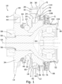
- a rolling bearing constituting a motor vehicle drive wheel assembly 10, comprising a fixed sub-assembly 12, intended to be secured to a suspension member of a motor vehicle (not shown) and defining an axis of revolution XX , a rotating sub-assembly 14, capable of rotating around the axis of revolution XX inside the fixed sub-assembly 12, and rolling guide bodies 16, 18 between the rotating sub-assembly 14 and the sub-assembly fixed assembly 12.
- the fixed subassembly 12 is here constituted by a solid one-piece outer metal ring 20 on which are formed in this embodiment two coaxial outer raceways 22, 24 defining the axis of revolution XX, one of the raceways exteriors 22 being intended to be positioned on an exterior side of the vehicle, and the other 24 being intended to be positioned on an interior side of the vehicle, that is to say closer to a median longitudinal vertical plane of the vehicle.
- the outer ring further comprises at least one fixing flange 26 extending radially outwards, in which bores 28 are formed for fixing the fixing flange 26 to a suspension member 30, in this case a suspension leg pivot, via fixing elements 32.
- the rotating subassembly 14 comprises a wheel hub 34 which forms an inner bearing ring on the outer side of the vehicle, a second inner bearing ring 36 located on the inner side of the vehicle and a transmission bowl 38.
- the wheel hub 34 is a solid, one-piece metal part, which includes a flange 40 for fixing a drive wheel rim and/or a brake disc.
- the flange 40 has a flat support face 42 for the brake disc or the wheel rim, and is provided with fixing bores 44, allowing the insertion of fixing elements of the rim and/or the wheel rim. brake.
- On the wheel hub 34 a first inner raceway 46 is formed facing the first outer raceway 22.
- the transmission bowl 38 is a solid, one-piece metal part which, in this embodiment, has a solid end projecting portion 50 and a flared middle portion 52 delimiting a CV joint cavity 54 .
- the projecting portion 50 of the transmission bowl 38 is grooved and mounted free, adjusted or shrinked in a grooved tubular cavity 56 of the wheel hub 34, forming a grooved contact interface.
- we have illustrated with on the figure 1 means for fixing the transmission bowl 38 and the wheel hub 34, which use a nut 58 screwed to a threaded end of the projecting portion 50, and bearing against a shoulder of the wheel hub 34.
- the inner ring of bearing 36 on the interior side of the vehicle is hooped onto a cylindrical hooping surface 60 of the wheel hub 34 and pinched in the axial direction between the wheel hub 34 and the transmission bowl 38.
- An inner raceway 62 is formed on the inner bearing ring 36 facing the outer raceway 24 located on the inner side of the vehicle.
- the rolling bodies 16, 18 form on the one hand a first row of rolling bodies 16 which roll on the outer raceway 22 and the inner raceway 46 on the exterior side of the vehicle, and on the other hand a second row of bodies rolling wheels 18 which roll on the outer raceway 24 and the inner raceway 62 on the interior side of the vehicle.
- sealing devices located on the exterior side of the vehicle, positioned between the outer ring 20 and the wheel hub 34, and a sealing device 66 located on the side interior of the vehicle, positioned between the outer ring 20 and the inner bearing ring 36.
- the inner raceway 46 is formed on a rolling ring attached to the wheel hub 34.
- the inner ring 36 on the inner side of the vehicle can be fixed to the wheel hub 34 by a bolt and n 'have, if necessary, no contact with the transmission bowl 38.
- the attachment between the transmission bowl 38 and the wheel hub 34 can be achieved by any means.
- the bearing may only have one row of rolling bodies 16, and these may consist of balls or rollers.
- the sealing device 66 located on the interior side of the vehicle, illustrated in detail on the figure 2 , and which provides sealing between the outer bearing ring 20 and the inner bearing ring 36, and more specifically the protection of a volume V located between the raceway 24 of the outer ring 20 and the raceway 62 of the inner ring 36.
- the outer bearing ring 20 comprises a shrinking surface 68, which is here cylindrical and turned towards the axis of revolution XX, and an end wall 70, which makes it possible to define a reference plane PE of the outer bearing ring 20, perpendicular to the axis of revolution XX and tangent to the end face 70.
- the shrinking surface 68 extends, in the axial direction and in the circumferential direction, in a zone of the outer ring 20 located between the raceway 24 located on the interior side of the vehicle and the end face 70.
- the shrinking surface 68 of the outer ring is further from the axis of revolution XX than a pitch circle C of the row of rolling bodies 18, and, in this embodiment, further away from the axis of revolution XX than a bottom of the track FE of the raceway 24 of the outer ring 20.
- the inner bearing ring 36 also includes a hooping surface 72, which is here cylindrical and turned radially outwards, and an end wall 74, which makes it possible to define a reference plane PI of the inner bearing ring 36 , perpendicular to the axis of revolution XX and tangent to the end face 74.
- the shrinking surface 72 extends, in the axial direction and in the circumferential direction, in an area of the inner ring located between the raceway 62 located on the interior side of the vehicle and the end face 74.
- the face d The end 74 of the inner bearing ring and the end face 70 of the outer bearing ring are turned in a common direction D parallel to the reference axis XX, which will be an axial reference direction for the rest of the 'exposed.
- the reference plane PI of the inner bearing ring 36 is located at a distance from the reference plane PE of the outer bearing ring 20 and offset in the axial reference direction D, so that the inner bearing ring 36 projects relative to the outer bearing ring 20 in the axial reference direction D, and crosses the reference plane PE of the outer bearing ring 20.
- at least part of the bearing surface shrink-fit surface 72 of the inner bearing ring 36 is located on one side of the reference plane PE of the outer bearing ring 20 opposite the shrink-fit surface 68 of the outer bearing ring 20.
- the sealing device 66 comprises an outer structure 76 secured to the outer ring 20, and an inner structure 78 secured to the inner ring 36.
- the external structure 76 comprises a hooping portion 80 hooped on the hooping surface 68 of the outer ring 20, and a functional portion forming a gutter 82 open radially towards the outside, a baffle wall 84, and, in this mode of embodiment, two seal lips 86.
- the gutter 82 has a bottom 822 and side walls 824, which are located axially on either side of the bottom and are further away from the axis of revolution than the bottom.
- the external structure 76 comprises a rigid frame 762, for example made of sheet metal or plastic, and an overmolding 764.
- the frame 762 forms the hooping portion 80 and the gutter 82, while the overmolding 764 forms the baffle wall 84 and the seal lips 86.
- the interior structure 78 comprises a hooping portion 88 hooped on the hooping surface 72 of the inner ring 36, and a functional portion forming a seal seat 90 and a baffle wall 92 located opposite the baffle wall 84 of the exterior structure 76 to delimit a chicane passage S between the interior structure 78 and the exterior structure 76.
- the seal lips 86 are elastically deformable and bear on the seal seat 90 which, in this embodiment, is cylindrical .
- the interior structure 78 and the exterior structure 76 of the sealing device together delimit an annular housing L for the seal seat 90 and the seal lips 86, housing into which the chicane passage S opens and in communication with the internal volume V delimited by the raceway 24 of the outer bearing ring 20 and by the raceway 62 of the inner bearing ring 36.
- the hooping portion 88 and the functional portion of the interior structure 78 are on either side of the reference plane PI of the inner ring 36. It is thus possible to position the seal seat 90 at a closer distance from the axis of revolution XX than the shrinking portion 88. This arrangement aims to minimize the diameter of the seal seat 90 and makes it possible to minimize the friction torque between the seal lips 86 and the seal seat 90, and to reduce the heat produced by this friction.
- the chicane passage S has an entrance E delimited by an entrance portion of the chicane wall 84 of the exterior structure 76 and by an entrance portion of the chicane wall 92 of the interior structure 78.
- the entrance E of the chicane passage S and the hooping portion 80 of the external structure 76 are located axially on either side of the gutter 82.
- the chicane passage S and the gutter 82 are located on the same first side of the plane of reference PE of the outer ring 20 opposite the side of the reference plane PE where the hooping portion 80 of the outer structure 76 is located.
- the entrance to the chicane passage is further from the axis of revolution XX than the seat of seal 90.
- the baffle wall 84 of the outer structure 76 is formed by annular ribs 94 which project axially towards the baffle wall 92 of the inner structure 78.
- the baffle wall 92 of the inner structure 78 is formed by one or more annular ribs 96, which project axially towards the baffle wall 84 of the exterior structure 76 and are interposed in spaces between the annular ribs 94 of the exterior structure 76.
- the annular ribs 94 of the exterior structure 76 form one or more additional gutters 98 located inside the baffle passage S.
- the baffle wall 92 comprises frustoconical facets 922 facing the axis of revolution and frustoconical walls 924 facing radially outwards.
- the entry E of the chicane passage S is annular and turned in an axial direction opposite to the axial direction of reference D, towards the outer bearing ring 20.
- the entry E is further away from the axis of revolution XX than the bottom 822 of the gutter 82.
- the entrance E is preferably further away from the axis of revolution XX than the pitch circle C defined by the row of rolling bodies 18.
- the inlet portion of the baffle wall 92 of the interior structure 78 is preferably frustoconical as illustrated, so as to converge towards a vertex further away from the reference plane of the outer ring PE than the inlet E.
- the inlet portion of the baffle wall 84 of the outer structure 76 is preferably frustoconical as illustrated in the figures, so as to converge towards a vertex further away from the reference plane PE of the outer ring than the inlet E .
- the gutter 82 is located at least partially in axial overlap with the hooping surface 72 of the inner bearing ring 36 and with the hooping portion 88 of the interior structure 78.
- the baffle wall 84 of the outer structure 76 is located entirely on one side of the reference plane PI of the inner bearing ring 36, and entirely on one side of the gutter 82, so that the gutter 82 is located axially between the shrinking portion 80 of the exterior structure 76 and the baffle wall 84 of the exterior structure 76.
- the functional portion of the interior structure 78 can also form a seat 99 or a support for a static seal 102 cooperating directly or indirectly with the flared middle portion 52 of the transmission bowl 38 and/or an interface for fixing a sleeve of protection 104 of the transmission bowl 38.
- the interior structure 78 of the sealing device 66 comprises a reinforcement 782, preferably metallic, which forms the hooping portion 72 and can also form the seal seat 90.
- the seal seat 90 can be formed on an annular part attached to the frame 782, this frame 782 may or may not be made of a non-metallic material.
- the interior structure 78 further comprises a second part 784 fixed to a connection portion 785 of the frame 782 by any appropriate means, in particular by gluing, overmolding or mechanical fixing, for example by hooping or by fixing elements , or, as illustrated on the figures 1 to 3 , by elastic attachment.
- the connection portion 785 of the frame 782 here projects axially relative to the joint seat 90 in the reference direction D.
- the second part 784 can be made of plastic. It constitutes a deflector which forms the baffle wall 92 of the interior structure and where appropriate the seat 99 or the support for static seal 102, or even the static seal 102 itself.
- a third part 786 delimits with the second part 784 an additional gutter 106 near the joint seat 90.
- the part constituting the deflector can also form the seal seat.
- the interior structure 78 also serves as a support for an encoder 108, preferably annular, positioned facing a side wall 824 or the bottom 822 of the gutter 82, and which may in particular be a multipolar magnetic encoder or a tone wheel. It is thus possible, with a sensor 110 penetrating locally into the gutter 82, to read data remotely through the wall 824 of the gutter 82 , in particular position data, coded on the encoder 108. The reading can be radial if the encoder 108 is positioned on the hooping portion 88 of the interior structure 78, and if the hooping is controlled so as not to induce uncontrolled deformation of the encoder 108.
- an encoder 108 preferably annular, positioned facing a side wall 824 or the bottom 822 of the gutter 82, and which may in particular be a multipolar magnetic encoder or a tone wheel. It is thus possible, with a sensor 110 penetrating locally into the gutter 82, to read data remotely through the wall 824 of
- the reading is axial, as illustrated on the figures 1 And 2 , the encoder 108 then being supported by a plane annular flange 112 projecting radially from the hooping portion 88 towards the outer bearing ring 20.
- the flange plane annular ring 112 positioned facing and at a short distance from the side wall 824, can be advantageous, in that it makes it possible to confine the grease inside the volume V, making it possible, if necessary, to eliminate one of the seal lips 86 and thus contributing to a reduction in friction torque.
- FIG. 5 another variant is illustrated, which differs from the embodiment of the figures 1 And 2 by the fact that the frame 762 of the external structure 76 of the sealing device is constituted by two parts 7621, 7622 fixed to one another by any appropriate means, here by hooping and mechanical hooking.
- the seal seat may comprise a flat annular face, parallel to the reference plane of the inner ring, the external structure of the sealing device then comprising a seal lip bearing axially against this flat face.
- the sealing device described can be used in applications other than the protection of a wheel bearing, and will advantageously be applicable to any plain or rolling bearing, and in particular to any plain or rolling bearing whose outer ring is intended to be fixed and the inner ring is intended to rotate.
- the raceways 22, 24, 46, 62 will be referred to as guideways.
Landscapes
- Engineering & Computer Science (AREA)
- General Engineering & Computer Science (AREA)
- Mechanical Engineering (AREA)
- Rolling Contact Bearings (AREA)
- Sealing Of Bearings (AREA)
- Sealing Using Fluids, Sealing Without Contact, And Removal Of Oil (AREA)
- Sealing With Elastic Sealing Lips (AREA)
Applications Claiming Priority (2)
| Application Number | Priority Date | Filing Date | Title |
|---|---|---|---|
| FR2100908A FR3119427B1 (fr) | 2021-01-29 | 2021-01-29 | Palier lisse ou à roulement équipé d’un dispositif d’étanchéité avec un siège de joint proche de l’axe de révolution |
| PCT/EP2021/087876 WO2022161734A1 (fr) | 2021-01-29 | 2021-12-30 | Palier lisse ou a roulement equipe d'un dispositif d'etancheite avec un siege de joint proche de l'axe de revolution |
Publications (2)
| Publication Number | Publication Date |
|---|---|
| EP4204700A1 EP4204700A1 (fr) | 2023-07-05 |
| EP4204700B1 true EP4204700B1 (fr) | 2024-04-10 |
Family
ID=74860264
Family Applications (1)
| Application Number | Title | Priority Date | Filing Date |
|---|---|---|---|
| EP21840645.2A Active EP4204700B1 (fr) | 2021-01-29 | 2021-12-30 | Palier lisse ou à roulement equipé d'un dispositif d'étanchéité avec un siège de joint proche de l'axe de révolution |
Country Status (6)
| Country | Link |
|---|---|
| US (1) | US12338861B2 (https=) |
| EP (1) | EP4204700B1 (https=) |
| JP (1) | JP7837986B2 (https=) |
| CN (1) | CN116802411A (https=) |
| FR (1) | FR3119427B1 (https=) |
| WO (1) | WO2022161734A1 (https=) |
Families Citing this family (1)
| Publication number | Priority date | Publication date | Assignee | Title |
|---|---|---|---|---|
| FR3145309B1 (fr) * | 2023-01-26 | 2025-01-31 | Ntn Snr Roulements | Assemblage de ROue de véhicule automobile |
Family Cites Families (10)
| Publication number | Priority date | Publication date | Assignee | Title |
|---|---|---|---|---|
| FR2000720A1 (https=) | 1968-01-25 | 1969-09-12 | Windmoeller & Hoelscher | |
| ITTO20010708A1 (it) * | 2001-07-19 | 2003-01-19 | Skf Ind Spa | Dispositivo di tenuta per cuscinetti. |
| JP4040331B2 (ja) * | 2002-03-08 | 2008-01-30 | Ntn株式会社 | 車輪用軸受装置 |
| JP5121001B2 (ja) * | 2006-12-01 | 2013-01-16 | Ntn株式会社 | 車輪用軸受装置 |
| JP2008202733A (ja) * | 2007-02-21 | 2008-09-04 | Ntn Corp | センサ付シール装置および車輪用軸受装置 |
| JP2008286265A (ja) * | 2007-05-16 | 2008-11-27 | Ntn Corp | 回転速度検出装置付き車輪用軸受装置 |
| US8356941B2 (en) * | 2010-03-08 | 2013-01-22 | Amsted Rail Company, Inc. | Railway car bearing seal |
| US9377055B2 (en) * | 2012-02-16 | 2016-06-28 | Schaeffler Technologies AG & Co. KG | Wheel bearing arrangement with encoder protection and centering device |
| DE102017108386A1 (de) * | 2017-04-20 | 2018-10-25 | Schaeffler Technologies AG & Co. KG | Dichtungsanordnung eines Radlagers |
| KR102536970B1 (ko) * | 2019-02-15 | 2023-05-26 | 주식회사 일진글로벌 | 씰링 기능이 향상된 차량용 휠베어링 |
-
2021
- 2021-01-29 FR FR2100908A patent/FR3119427B1/fr active Active
- 2021-12-30 US US18/262,742 patent/US12338861B2/en active Active
- 2021-12-30 EP EP21840645.2A patent/EP4204700B1/fr active Active
- 2021-12-30 JP JP2023545949A patent/JP7837986B2/ja active Active
- 2021-12-30 WO PCT/EP2021/087876 patent/WO2022161734A1/fr not_active Ceased
- 2021-12-30 CN CN202180092459.7A patent/CN116802411A/zh active Pending
Also Published As
| Publication number | Publication date |
|---|---|
| FR3119427B1 (fr) | 2023-03-10 |
| CN116802411A (zh) | 2023-09-22 |
| JP2024504465A (ja) | 2024-01-31 |
| FR3119427A1 (fr) | 2022-08-05 |
| US12338861B2 (en) | 2025-06-24 |
| JP7837986B2 (ja) | 2026-03-31 |
| EP4204700A1 (fr) | 2023-07-05 |
| US20240392835A1 (en) | 2024-11-28 |
| WO2022161734A1 (fr) | 2022-08-04 |
Similar Documents
| Publication | Publication Date | Title |
|---|---|---|
| FR2729440A1 (fr) | Palier a roulement, notamment palier arriere d'alternateur de vehicule automobile | |
| FR2489754A1 (fr) | Ensemble de moyeu de roue pour vehicule automobile | |
| EP0631072A1 (fr) | Joint d'étanchéité pour arbre tournant | |
| EP2564209A1 (fr) | Assemblage instrumenté et rondelle frein associée | |
| EP1865206A2 (fr) | Mécanisme d'entrainement par courroie | |
| EP4204700B1 (fr) | Palier lisse ou à roulement equipé d'un dispositif d'étanchéité avec un siège de joint proche de l'axe de révolution | |
| EP4204701B1 (fr) | Roulement de roue equipé d'un dispositif d'étanchéité à gouttière et chicane | |
| FR3052104A1 (fr) | Assemblage de roue motrice de vehicule automobile | |
| FR2778217A1 (fr) | Butee de debrayage a amortissement de vibration | |
| FR2684729A1 (fr) | Logement pour fixation radiale d'un roulement. | |
| EP1264113A1 (fr) | Palier a roulement de colonne de direction pour vehicules automobiles | |
| WO2011135209A2 (fr) | Assemblage instrumenté pour fusée d'essieu | |
| EP2564210A2 (fr) | Assemblage instrumente pour fusee d'essieu et procede de montage | |
| EP4008929B1 (fr) | Ensemble satellite, train epicycloïdale d'engrenages muni d'un tel ensemble et boite de transmission de puissance | |
| EP4281689B1 (fr) | Boitier de transmission et engin roulant equipe d'un tel boitier de transmission | |
| EP1348611B1 (fr) | Dispositif de fixation de pivot de roue de véhicule automobile | |
| EP1707843A1 (fr) | Double volant amortisseur pour véhicule automobile | |
| WO2002021021A1 (fr) | Appareil d'accouplement hydrocinetique, notamment pour vehicule automobile | |
| EP2053248A2 (fr) | Mécanisme d'entraînement par courroie et son procédé de fabrication | |
| FR3106635A1 (fr) | Assemblage de ROue de véhicule automobile | |
| FR2729441A1 (fr) | Dispositif pour monter un arbre de sortie dans un carter de transmission de vehicule automobile | |
| EP4406756B1 (fr) | Assemblage de roue de vehicule automobile | |
| EP4522469B1 (fr) | Actionneur électrique de frein à disque avec reducteur differentiel amorti en vibrations, composants, frein et procédé d'assemblage | |
| FR2908728A1 (fr) | Dispositif de fixation de pivot de roue de vehicule automobile. | |
| FR2745051A1 (fr) | Montage de butee de debrayage, notamment pour vehicule automobile |
Legal Events
| Date | Code | Title | Description |
|---|---|---|---|
| STAA | Information on the status of an ep patent application or granted ep patent |
Free format text: STATUS: UNKNOWN |
|
| STAA | Information on the status of an ep patent application or granted ep patent |
Free format text: STATUS: THE INTERNATIONAL PUBLICATION HAS BEEN MADE |
|
| PUAI | Public reference made under article 153(3) epc to a published international application that has entered the european phase |
Free format text: ORIGINAL CODE: 0009012 |
|
| STAA | Information on the status of an ep patent application or granted ep patent |
Free format text: STATUS: REQUEST FOR EXAMINATION WAS MADE |
|
| 17P | Request for examination filed |
Effective date: 20230328 |
|
| AK | Designated contracting states |
Kind code of ref document: A1 Designated state(s): AL AT BE BG CH CY CZ DE DK EE ES FI FR GB GR HR HU IE IS IT LI LT LU LV MC MK MT NL NO PL PT RO RS SE SI SK SM TR |
|
| RAP3 | Party data changed (applicant data changed or rights of an application transferred) |
Owner name: NTN EUROPE |
|
| GRAP | Despatch of communication of intention to grant a patent |
Free format text: ORIGINAL CODE: EPIDOSNIGR1 |
|
| STAA | Information on the status of an ep patent application or granted ep patent |
Free format text: STATUS: GRANT OF PATENT IS INTENDED |
|
| DAV | Request for validation of the european patent (deleted) | ||
| DAX | Request for extension of the european patent (deleted) | ||
| INTG | Intention to grant announced |
Effective date: 20240102 |
|
| GRAS | Grant fee paid |
Free format text: ORIGINAL CODE: EPIDOSNIGR3 |
|
| GRAA | (expected) grant |
Free format text: ORIGINAL CODE: 0009210 |
|
| STAA | Information on the status of an ep patent application or granted ep patent |
Free format text: STATUS: THE PATENT HAS BEEN GRANTED |
|
| AK | Designated contracting states |
Kind code of ref document: B1 Designated state(s): AL AT BE BG CH CY CZ DE DK EE ES FI FR GB GR HR HU IE IS IT LI LT LU LV MC MK MT NL NO PL PT RO RS SE SI SK SM TR |
|
| REG | Reference to a national code |
Ref country code: GB Ref legal event code: FG4D Free format text: NOT ENGLISH |
|
| REG | Reference to a national code |
Ref country code: CH Ref legal event code: EP |
|
| REG | Reference to a national code |
Ref country code: DE Ref legal event code: R096 Ref document number: 602021011744 Country of ref document: DE |
|
| REG | Reference to a national code |
Ref country code: IE Ref legal event code: FG4D Free format text: LANGUAGE OF EP DOCUMENT: FRENCH |
|
| REG | Reference to a national code |
Ref country code: LT Ref legal event code: MG9D |
|
| REG | Reference to a national code |
Ref country code: NL Ref legal event code: MP Effective date: 20240410 |
|
| REG | Reference to a national code |
Ref country code: AT Ref legal event code: MK05 Ref document number: 1675186 Country of ref document: AT Kind code of ref document: T Effective date: 20240410 |
|
| PG25 | Lapsed in a contracting state [announced via postgrant information from national office to epo] |
Ref country code: NL Free format text: LAPSE BECAUSE OF FAILURE TO SUBMIT A TRANSLATION OF THE DESCRIPTION OR TO PAY THE FEE WITHIN THE PRESCRIBED TIME-LIMIT Effective date: 20240410 |
|
| PG25 | Lapsed in a contracting state [announced via postgrant information from national office to epo] |
Ref country code: NL Free format text: LAPSE BECAUSE OF FAILURE TO SUBMIT A TRANSLATION OF THE DESCRIPTION OR TO PAY THE FEE WITHIN THE PRESCRIBED TIME-LIMIT Effective date: 20240410 |
|
| PG25 | Lapsed in a contracting state [announced via postgrant information from national office to epo] |
Ref country code: IS Free format text: LAPSE BECAUSE OF FAILURE TO SUBMIT A TRANSLATION OF THE DESCRIPTION OR TO PAY THE FEE WITHIN THE PRESCRIBED TIME-LIMIT Effective date: 20240810 |
|
| PG25 | Lapsed in a contracting state [announced via postgrant information from national office to epo] |
Ref country code: BG Free format text: LAPSE BECAUSE OF FAILURE TO SUBMIT A TRANSLATION OF THE DESCRIPTION OR TO PAY THE FEE WITHIN THE PRESCRIBED TIME-LIMIT Effective date: 20240410 |
|
| PG25 | Lapsed in a contracting state [announced via postgrant information from national office to epo] |
Ref country code: HR Free format text: LAPSE BECAUSE OF FAILURE TO SUBMIT A TRANSLATION OF THE DESCRIPTION OR TO PAY THE FEE WITHIN THE PRESCRIBED TIME-LIMIT Effective date: 20240410 Ref country code: FI Free format text: LAPSE BECAUSE OF FAILURE TO SUBMIT A TRANSLATION OF THE DESCRIPTION OR TO PAY THE FEE WITHIN THE PRESCRIBED TIME-LIMIT Effective date: 20240410 |
|
| PG25 | Lapsed in a contracting state [announced via postgrant information from national office to epo] |
Ref country code: GR Free format text: LAPSE BECAUSE OF FAILURE TO SUBMIT A TRANSLATION OF THE DESCRIPTION OR TO PAY THE FEE WITHIN THE PRESCRIBED TIME-LIMIT Effective date: 20240711 |
|
| PG25 | Lapsed in a contracting state [announced via postgrant information from national office to epo] |
Ref country code: PT Free format text: LAPSE BECAUSE OF FAILURE TO SUBMIT A TRANSLATION OF THE DESCRIPTION OR TO PAY THE FEE WITHIN THE PRESCRIBED TIME-LIMIT Effective date: 20240812 |
|
| PG25 | Lapsed in a contracting state [announced via postgrant information from national office to epo] |
Ref country code: ES Free format text: LAPSE BECAUSE OF FAILURE TO SUBMIT A TRANSLATION OF THE DESCRIPTION OR TO PAY THE FEE WITHIN THE PRESCRIBED TIME-LIMIT Effective date: 20240410 |
|
| PG25 | Lapsed in a contracting state [announced via postgrant information from national office to epo] |
Ref country code: AT Free format text: LAPSE BECAUSE OF FAILURE TO SUBMIT A TRANSLATION OF THE DESCRIPTION OR TO PAY THE FEE WITHIN THE PRESCRIBED TIME-LIMIT Effective date: 20240410 |
|
| PG25 | Lapsed in a contracting state [announced via postgrant information from national office to epo] |
Ref country code: PL Free format text: LAPSE BECAUSE OF FAILURE TO SUBMIT A TRANSLATION OF THE DESCRIPTION OR TO PAY THE FEE WITHIN THE PRESCRIBED TIME-LIMIT Effective date: 20240410 |
|
| PG25 | Lapsed in a contracting state [announced via postgrant information from national office to epo] |
Ref country code: LV Free format text: LAPSE BECAUSE OF FAILURE TO SUBMIT A TRANSLATION OF THE DESCRIPTION OR TO PAY THE FEE WITHIN THE PRESCRIBED TIME-LIMIT Effective date: 20240410 |
|
| PG25 | Lapsed in a contracting state [announced via postgrant information from national office to epo] |
Ref country code: PT Free format text: LAPSE BECAUSE OF FAILURE TO SUBMIT A TRANSLATION OF THE DESCRIPTION OR TO PAY THE FEE WITHIN THE PRESCRIBED TIME-LIMIT Effective date: 20240812 Ref country code: PL Free format text: LAPSE BECAUSE OF FAILURE TO SUBMIT A TRANSLATION OF THE DESCRIPTION OR TO PAY THE FEE WITHIN THE PRESCRIBED TIME-LIMIT Effective date: 20240410 Ref country code: NO Free format text: LAPSE BECAUSE OF FAILURE TO SUBMIT A TRANSLATION OF THE DESCRIPTION OR TO PAY THE FEE WITHIN THE PRESCRIBED TIME-LIMIT Effective date: 20240710 Ref country code: LV Free format text: LAPSE BECAUSE OF FAILURE TO SUBMIT A TRANSLATION OF THE DESCRIPTION OR TO PAY THE FEE WITHIN THE PRESCRIBED TIME-LIMIT Effective date: 20240410 Ref country code: IS Free format text: LAPSE BECAUSE OF FAILURE TO SUBMIT A TRANSLATION OF THE DESCRIPTION OR TO PAY THE FEE WITHIN THE PRESCRIBED TIME-LIMIT Effective date: 20240810 Ref country code: HR Free format text: LAPSE BECAUSE OF FAILURE TO SUBMIT A TRANSLATION OF THE DESCRIPTION OR TO PAY THE FEE WITHIN THE PRESCRIBED TIME-LIMIT Effective date: 20240410 Ref country code: GR Free format text: LAPSE BECAUSE OF FAILURE TO SUBMIT A TRANSLATION OF THE DESCRIPTION OR TO PAY THE FEE WITHIN THE PRESCRIBED TIME-LIMIT Effective date: 20240711 Ref country code: FI Free format text: LAPSE BECAUSE OF FAILURE TO SUBMIT A TRANSLATION OF THE DESCRIPTION OR TO PAY THE FEE WITHIN THE PRESCRIBED TIME-LIMIT Effective date: 20240410 Ref country code: ES Free format text: LAPSE BECAUSE OF FAILURE TO SUBMIT A TRANSLATION OF THE DESCRIPTION OR TO PAY THE FEE WITHIN THE PRESCRIBED TIME-LIMIT Effective date: 20240410 Ref country code: BG Free format text: LAPSE BECAUSE OF FAILURE TO SUBMIT A TRANSLATION OF THE DESCRIPTION OR TO PAY THE FEE WITHIN THE PRESCRIBED TIME-LIMIT Effective date: 20240410 Ref country code: AT Free format text: LAPSE BECAUSE OF FAILURE TO SUBMIT A TRANSLATION OF THE DESCRIPTION OR TO PAY THE FEE WITHIN THE PRESCRIBED TIME-LIMIT Effective date: 20240410 Ref country code: RS Free format text: LAPSE BECAUSE OF FAILURE TO SUBMIT A TRANSLATION OF THE DESCRIPTION OR TO PAY THE FEE WITHIN THE PRESCRIBED TIME-LIMIT Effective date: 20240710 |
|
| REG | Reference to a national code |
Ref country code: DE Ref legal event code: R097 Ref document number: 602021011744 Country of ref document: DE |
|
| PG25 | Lapsed in a contracting state [announced via postgrant information from national office to epo] |
Ref country code: DK Free format text: LAPSE BECAUSE OF FAILURE TO SUBMIT A TRANSLATION OF THE DESCRIPTION OR TO PAY THE FEE WITHIN THE PRESCRIBED TIME-LIMIT Effective date: 20240410 |
|
| PG25 | Lapsed in a contracting state [announced via postgrant information from national office to epo] |
Ref country code: EE Free format text: LAPSE BECAUSE OF FAILURE TO SUBMIT A TRANSLATION OF THE DESCRIPTION OR TO PAY THE FEE WITHIN THE PRESCRIBED TIME-LIMIT Effective date: 20240410 |
|
| PG25 | Lapsed in a contracting state [announced via postgrant information from national office to epo] |
Ref country code: CZ Free format text: LAPSE BECAUSE OF FAILURE TO SUBMIT A TRANSLATION OF THE DESCRIPTION OR TO PAY THE FEE WITHIN THE PRESCRIBED TIME-LIMIT Effective date: 20240410 |
|
| PG25 | Lapsed in a contracting state [announced via postgrant information from national office to epo] |
Ref country code: SK Free format text: LAPSE BECAUSE OF FAILURE TO SUBMIT A TRANSLATION OF THE DESCRIPTION OR TO PAY THE FEE WITHIN THE PRESCRIBED TIME-LIMIT Effective date: 20240410 Ref country code: RO Free format text: LAPSE BECAUSE OF FAILURE TO SUBMIT A TRANSLATION OF THE DESCRIPTION OR TO PAY THE FEE WITHIN THE PRESCRIBED TIME-LIMIT Effective date: 20240410 |
|
| PG25 | Lapsed in a contracting state [announced via postgrant information from national office to epo] |
Ref country code: SM Free format text: LAPSE BECAUSE OF FAILURE TO SUBMIT A TRANSLATION OF THE DESCRIPTION OR TO PAY THE FEE WITHIN THE PRESCRIBED TIME-LIMIT Effective date: 20240410 |
|
| PG25 | Lapsed in a contracting state [announced via postgrant information from national office to epo] |
Ref country code: SM Free format text: LAPSE BECAUSE OF FAILURE TO SUBMIT A TRANSLATION OF THE DESCRIPTION OR TO PAY THE FEE WITHIN THE PRESCRIBED TIME-LIMIT Effective date: 20240410 Ref country code: SK Free format text: LAPSE BECAUSE OF FAILURE TO SUBMIT A TRANSLATION OF THE DESCRIPTION OR TO PAY THE FEE WITHIN THE PRESCRIBED TIME-LIMIT Effective date: 20240410 Ref country code: RO Free format text: LAPSE BECAUSE OF FAILURE TO SUBMIT A TRANSLATION OF THE DESCRIPTION OR TO PAY THE FEE WITHIN THE PRESCRIBED TIME-LIMIT Effective date: 20240410 Ref country code: EE Free format text: LAPSE BECAUSE OF FAILURE TO SUBMIT A TRANSLATION OF THE DESCRIPTION OR TO PAY THE FEE WITHIN THE PRESCRIBED TIME-LIMIT Effective date: 20240410 Ref country code: DK Free format text: LAPSE BECAUSE OF FAILURE TO SUBMIT A TRANSLATION OF THE DESCRIPTION OR TO PAY THE FEE WITHIN THE PRESCRIBED TIME-LIMIT Effective date: 20240410 Ref country code: CZ Free format text: LAPSE BECAUSE OF FAILURE TO SUBMIT A TRANSLATION OF THE DESCRIPTION OR TO PAY THE FEE WITHIN THE PRESCRIBED TIME-LIMIT Effective date: 20240410 |
|
| PG25 | Lapsed in a contracting state [announced via postgrant information from national office to epo] |
Ref country code: IT Free format text: LAPSE BECAUSE OF FAILURE TO SUBMIT A TRANSLATION OF THE DESCRIPTION OR TO PAY THE FEE WITHIN THE PRESCRIBED TIME-LIMIT Effective date: 20240410 |
|
| PLBE | No opposition filed within time limit |
Free format text: ORIGINAL CODE: 0009261 |
|
| STAA | Information on the status of an ep patent application or granted ep patent |
Free format text: STATUS: NO OPPOSITION FILED WITHIN TIME LIMIT |
|
| 26N | No opposition filed |
Effective date: 20250113 |
|
| PG25 | Lapsed in a contracting state [announced via postgrant information from national office to epo] |
Ref country code: SI Free format text: LAPSE BECAUSE OF FAILURE TO SUBMIT A TRANSLATION OF THE DESCRIPTION OR TO PAY THE FEE WITHIN THE PRESCRIBED TIME-LIMIT Effective date: 20240410 |
|
| PG25 | Lapsed in a contracting state [announced via postgrant information from national office to epo] |
Ref country code: MC Free format text: LAPSE BECAUSE OF FAILURE TO SUBMIT A TRANSLATION OF THE DESCRIPTION OR TO PAY THE FEE WITHIN THE PRESCRIBED TIME-LIMIT Effective date: 20240410 |
|
| REG | Reference to a national code |
Ref country code: CH Ref legal event code: PL |
|
| PG25 | Lapsed in a contracting state [announced via postgrant information from national office to epo] |
Ref country code: LU Free format text: LAPSE BECAUSE OF NON-PAYMENT OF DUE FEES Effective date: 20241230 |
|
| PG25 | Lapsed in a contracting state [announced via postgrant information from national office to epo] |
Ref country code: SE Free format text: LAPSE BECAUSE OF FAILURE TO SUBMIT A TRANSLATION OF THE DESCRIPTION OR TO PAY THE FEE WITHIN THE PRESCRIBED TIME-LIMIT Effective date: 20240410 |
|
| REG | Reference to a national code |
Ref country code: BE Ref legal event code: MM Effective date: 20241231 |
|
| PG25 | Lapsed in a contracting state [announced via postgrant information from national office to epo] |
Ref country code: BE Free format text: LAPSE BECAUSE OF NON-PAYMENT OF DUE FEES Effective date: 20241231 |
|
| PG25 | Lapsed in a contracting state [announced via postgrant information from national office to epo] |
Ref country code: CH Free format text: LAPSE BECAUSE OF NON-PAYMENT OF DUE FEES Effective date: 20241231 |
|
| PG25 | Lapsed in a contracting state [announced via postgrant information from national office to epo] |
Ref country code: IE Free format text: LAPSE BECAUSE OF NON-PAYMENT OF DUE FEES Effective date: 20241230 |
|
| PGFP | Annual fee paid to national office [announced via postgrant information from national office to epo] |
Ref country code: DE Payment date: 20251211 Year of fee payment: 5 |
|
| PGFP | Annual fee paid to national office [announced via postgrant information from national office to epo] |
Ref country code: FR Payment date: 20251229 Year of fee payment: 5 |