EP4202766A1 - System and method for counting corrugations in a flexible material - Google Patents
System and method for counting corrugations in a flexible material Download PDFInfo
- Publication number
- EP4202766A1 EP4202766A1 EP22214536.9A EP22214536A EP4202766A1 EP 4202766 A1 EP4202766 A1 EP 4202766A1 EP 22214536 A EP22214536 A EP 22214536A EP 4202766 A1 EP4202766 A1 EP 4202766A1
- Authority
- EP
- European Patent Office
- Prior art keywords
- corrugations
- measuring area
- flexible material
- counting
- image recording
- Prior art date
- Legal status (The legal status is an assumption and is not a legal conclusion. Google has not performed a legal analysis and makes no representation as to the accuracy of the status listed.)
- Granted
Links
Images


Classifications
-
- G—PHYSICS
- G06—COMPUTING OR CALCULATING; COUNTING
- G06M—COUNTING MECHANISMS; COUNTING OF OBJECTS NOT OTHERWISE PROVIDED FOR
- G06M7/00—Counting of objects carried by a conveyor
- G06M7/02—Counting of objects carried by a conveyor wherein objects ahead of the sensing element are separated to produce a distinct gap between successive objects
- G06M7/06—Counting of flat articles, e.g. of sheets of paper
-
- G—PHYSICS
- G06—COMPUTING OR CALCULATING; COUNTING
- G06T—IMAGE DATA PROCESSING OR GENERATION, IN GENERAL
- G06T7/00—Image analysis
- G06T7/10—Segmentation; Edge detection
- G06T7/13—Edge detection
-
- G—PHYSICS
- G01—MEASURING; TESTING
- G01B—MEASURING LENGTH, THICKNESS OR SIMILAR LINEAR DIMENSIONS; MEASURING ANGLES; MEASURING AREAS; MEASURING IRREGULARITIES OF SURFACES OR CONTOURS
- G01B11/00—Measuring arrangements characterised by the use of optical techniques
- G01B11/24—Measuring arrangements characterised by the use of optical techniques for measuring contours or curvatures
-
- G—PHYSICS
- G06—COMPUTING OR CALCULATING; COUNTING
- G06M—COUNTING MECHANISMS; COUNTING OF OBJECTS NOT OTHERWISE PROVIDED FOR
- G06M3/00—Counters with additional facilities
- G06M3/02—Counters with additional facilities for performing an operation at a predetermined value of the count, e.g. arresting a machine
- G06M3/025—Counters with additional facilities for performing an operation at a predetermined value of the count, e.g. arresting a machine with dial, pointer, or similar type indicating means
-
- G—PHYSICS
- G06—COMPUTING OR CALCULATING; COUNTING
- G06T—IMAGE DATA PROCESSING OR GENERATION, IN GENERAL
- G06T7/00—Image analysis
- G06T7/70—Determining position or orientation of objects or cameras
-
- H—ELECTRICITY
- H04—ELECTRIC COMMUNICATION TECHNIQUE
- H04N—PICTORIAL COMMUNICATION, e.g. TELEVISION
- H04N23/00—Cameras or camera modules comprising electronic image sensors; Control thereof
- H04N23/56—Cameras or camera modules comprising electronic image sensors; Control thereof provided with illuminating means
-
- H—ELECTRICITY
- H04—ELECTRIC COMMUNICATION TECHNIQUE
- H04N—PICTORIAL COMMUNICATION, e.g. TELEVISION
- H04N5/00—Details of television systems
- H04N5/76—Television signal recording
- H04N5/765—Interface circuits between an apparatus for recording and another apparatus
- H04N5/77—Interface circuits between an apparatus for recording and another apparatus between a recording apparatus and a television camera
-
- G—PHYSICS
- G06—COMPUTING OR CALCULATING; COUNTING
- G06T—IMAGE DATA PROCESSING OR GENERATION, IN GENERAL
- G06T2207/00—Indexing scheme for image analysis or image enhancement
- G06T2207/30—Subject of image; Context of image processing
- G06T2207/30204—Marker
-
- G—PHYSICS
- G06—COMPUTING OR CALCULATING; COUNTING
- G06T—IMAGE DATA PROCESSING OR GENERATION, IN GENERAL
- G06T2207/00—Indexing scheme for image analysis or image enhancement
- G06T2207/30—Subject of image; Context of image processing
- G06T2207/30242—Counting objects in image
-
- H—ELECTRICITY
- H04—ELECTRIC COMMUNICATION TECHNIQUE
- H04N—PICTORIAL COMMUNICATION, e.g. TELEVISION
- H04N23/00—Cameras or camera modules comprising electronic image sensors; Control thereof
- H04N23/50—Constructional details
- H04N23/51—Housings
-
- H—ELECTRICITY
- H04—ELECTRIC COMMUNICATION TECHNIQUE
- H04N—PICTORIAL COMMUNICATION, e.g. TELEVISION
- H04N23/00—Cameras or camera modules comprising electronic image sensors; Control thereof
- H04N23/60—Control of cameras or camera modules
- H04N23/63—Control of cameras or camera modules by using electronic viewfinders
Definitions
- the invention relates to a system and method for counting corrugations in a flexible material, for example pleats in a fabric for window coverings, such as a pleated curtain.
- this production process comprises the production step of counting the necessary number of pleats or folds per fabric package. In practice, this is done manually. It is very time-consuming to do this accurately.
- the system mentioned in the preamble is provided with a carrier with a surface for positioning the flexible material, a light source for illuminating the flexible material on the carrier, receiving means for receiving light originating from the flexible material, counting means for determining the number of corrugations in the flexible material based on data from the receiving means.
- Such a system is known from US 3,935,997 .
- the known system comprises an endless feed belt for supply of pleated material for lamp shades from a roll past an assembly that counts the pleats in the passing material.
- the counting takes place by means of a photocell that captures light reflections from the pleats and a detector that converts the light reflections into pulses, which are counted.
- An operator keeps on marking the passing material manually when reaching the desired number of pulses, which is a measure of the number of pleats.
- the known system is not suitable for customising individual fabric packages for window coverings.
- the system according to the present invention is thereto characterized in that the carrier is provided with a measuring area and with aligning means for aligning the flexible material in the measuring area, in that the receiving means comprise a camera for making one or more image recordings of the measuring area and in that the counting means comprise a processor, which is arranged for counting the number of corrugations in one or more of the image recordings, wherein the system is further provided with means for displaying the number of counted corrugations in the flexible material in the measuring area.
- the method according to the present invention thereto comprises the following steps:
- the system and the method according to the invention offer an operator the opportunity to customise fabric packages for window coverings separately by counting the number of pleats dynamically.
- Suitable display means are a screen or a counter. The operator then receives direct feedback from the system of the situation at that moment.
- the processor is arranged for analysing the contrast between the flexible material and the measuring area in an image recording.
- the first preferred embodiment makes it possible to measure corrugations in various kinds of flexible materials, among which multi-layer fabrics, such as honeycomb pleats.
- the measuring area comprises light-permeable material and the light source forms a backlight source for the camera. This increases the contrast between the flexible material and the measuring area in the image recording further.
- the light source and the camera are arranged on opposite sides of the measuring area.
- the camera is accommodated in a housing, which housing is arranged on the surface of the carrier. The camera is now always in an aligned position with respect to the measuring area on the carrier.
- the aligning means comprise a stop, which defines a corner in the measuring area.
- the system according to the invention is further provided with marking tools for marking a line on the surface.
- the marking tools are arranged for projecting the line.
- the line serves as borderline for the measuring area and/or as cutting line. The operator can directly cut the flexible material with the desired number of corrugations to size along the cutting line.
- the marking tools for projecting the line are arranged for projecting the line along one of the legs of the corner of the stop.
- the processor is arranged for carrying out the following steps:
- the system can measure the number of corrugations very accurately, even with very translucent material, stains, patterns and/or colour gradient in the flexible material.
- the last step preferably takes place by the processor being arranged for carrying out the step of displaying an image recording, wherein the counted corrugations are marked. The operator can now check at a glance whether all present corrugations have actually been counted.
- the invention also relates to a computer program comprising instructions to let the system according to the invention carry out at least the steps b) up until f) of the method according to the invention.
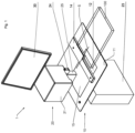
- Figure 1 shows a schematic view of a system 1 according to the invention in a preferred embodiment.
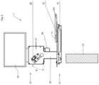
- Figure 2 shows a side view of the system 1 in cross-section.
- the system 1 is arranged for counting corrugations in a flexible material, for example pleats in a fabric of a window covering 100.
- the system 1 is thereto provided with a carrier 10 for positioning the flexible material 100.
- the carrier 10 comprises a substantially flat surface 11, on which a measuring area 12 is defined.
- the system 1 is provided with a light source 13 for illuminating the measuring area 12 on the carrier 10.
- the system 1 is further provided with a system 20 for receiving and analysing light originating from the flexible material 100 for counting the number of pleats in (a part of) the flexible material.
- the flexible material is a fabric with pleats for a window covering, such as a pleated curtain or pleated blind.
- a window covering such as a pleated curtain or pleated blind.
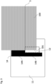
- Figure 3 shows a schematic display of a part of the carrier 10 with a pleated curtain fabric 100.
- the system 1 further comprises aligning means for aligning the fabric 100 in the measuring area 12 on the carrier 10.
- the aligning means comprise a stop 14 for aligning an edge 101 of the fabric.
- the aligning means also define the measuring area 12.
- the stop 14 is fixed on the carrier 10. In the shown preferred embodiment, the stop 14 adjoins the measuring area 12. In the shown preferred embodiment, the stop 14 delimits a corner of the measuring area 12.
- the stop 14 has a wider part 14A for aligning the pleated curtain fabric 100 and a smaller part 14B which borders on the measuring area 12. In use of the system 1, the measuring area 12 is partly covered by the flexible material 100 due to the stop 14.
- a screen 30 is provided for displaying the number of pleats that is present in the measuring area 12 at a certain moment.
- the screen preferably has a touchscreen.
- the screen can be part of the operating means.
- the system 20 comprises light-receiving means for receiving the light originating from the flexible material.
- the light-receiving means comprise a camera 22 for making image recordings of the measuring area 12 with the fabric.
- An example of such an image recording or image A1 is shown in figure 4 .
- the system 20 comprises a processor 23 for counting the number of pleats by analysing the image recordings.
- the processor is arranged for analysing the contrast in the image recordings between an edge 101 of the fabric 100 and the measuring area 12.
- the light source 13 forms a backlight source for the camera 22.
- the measuring area 12 is light-permeable and the light source 13 and the camera 22 are positioned on opposite sides of the measuring area 12 of the carrier 10.
- a suitable light source is a LED-light.
- a suitable, light-permeable material for the measuring area 12 is hardened glass, for example borosilicate glass.
- Figure 4 illustrates an image recording A1 of the measuring area 12 with the fabric 100 made using the camera 22.
- the pleats P that need to be counted are clearly visible.
- the processor 23 is arranged for counting the number of pleats P and carries out the following steps.
- the contrast between the fabric and the background, which is formed in system 1 by the measuring area 12 is made clearer.
- Suitable image processing techniques especially contrast-increasing image processing techniques, are hereto known in the relevant art and available for a person skilled in the art.
- a so-called binary image recording A2 is made, wherein the fabric is displayed in a certain colour and the background in a different colour, for example black.
- Figure 5 shows an example of such an image recording A2.
- a contour line C is determined, which follows the edge of the fabric with pleats.
- figure 6 shows an image recording A3, wherein the contour C is displayed.
- the contour C is determined as an x y chart, whereby for each x-coordinate the associated y-coordinate is determined by searching for the transition between the background (the measuring area 12) and the fabric 100.
- the contour C the coordinates of the peaks of the contour C, which correspond with the pleats, are determined. Suitable algorithms for this are known in the relevant art and available for a person skilled in the art.
- the processor 23 counts the number of peaks N and visualises this number.
- the number N is displayed on the screen 30.
- the peaks are marked in an image recording A4. This provides a user the option for a visual check to determine that all present pleats have been found and counted.
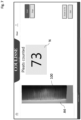
- Figure 7 shows a screenshot of the screen 30 of the system 1 with an example of an image recording A4.
- the system 1 displays the number of pleats dynamically.
- the user can slide the fabric over the carrier 10 in order to vary the number of pleats in the measuring area 12 until the desired number of pleats has been reached.
- the camera 22 preferably makes sufficient image recordings per unit of time to give the user the impression that the counting and the display of the number of pleats N takes places in real-time. In the preferred embodiment, a camera that depicts 17 frames per seconds is suitable.
- the system optionally comprises marking tools for marking the line S on the surface 11.
- the line S preferably runs over the transition between part 14A and 14B of the stop 14.
- the line S defines the measuring area 12.
- the line S forms an upper limit on the fabric 100 for the measured pleats of the fabric 100 and at the same time serves as cutting line.
- the marking tools comprise projection means 24, for example a laser, for temporary and contactless indication of the line S.
- the system 1 is provided with suitable operating means.
- the screen 30 is a touchscreen with, for example, operating buttons, such as 'start' and 'stop'.
- operating buttons such as 'start' and 'stop'.
- mechanical operating means such as a push button or a foot pedal, the operator can manually control the measurement.
- the system can start automatically upon presenting the fabric in the measuring area.
- the system 20 comprises a housing 21, wherein the camera 22 is accommodated.
- the marking tools 24 are fixed to the housing 21.
- the housing 21 is provided with a stand 25, which is fixed on the surface 11 of the carrier 10.
- a mounting plate 15 is hereto provided.
- the camera 22 is, with respect to the measuring area 12, set up obliquely on the carrier 10.
- the system 1 can be fixed on a larger work top by means of the carrier 10.
- the carrier 10 can for example be integrated in a suitable work top.
- the processor 23 can for example be placed under the work top.
- the screen 30 can for example stand on the housing 21.
- the present invention is based on the inventive idea of making a dynamic counting of the number of corrugations in a flexible material possible for all kinds of materials by carrying out a contrast measurement.
- the invention hereto provides a contrast analysing system and a method for the usage of the system.
- the above-mentioned contrast-increasing measures both separately as in combination, contribute to the pleats being detectable even with a small light gap between them.
- system 1 comprises for example multiple cameras 22 that each make image recordings of the measuring area.
- two cameras can for example be accommodated adjacent to each other.
- the image recordings of the different cameras can be merged into an image.
- Suitable techniques for this, such as ⁇ image stitching', are known in the relevant art.
- Usage of multiple cameras leads to a larger measuring area and makes the system according to the invention suitable for counting corrugations in flexible material with larger dimensions. The invention therefore extends to any embodiment falling within the scope of protection, such as defined in the claims and seen in the light of the preceding description and accompanying figures.
Landscapes
- Engineering & Computer Science (AREA)
- Physics & Mathematics (AREA)
- General Physics & Mathematics (AREA)
- Theoretical Computer Science (AREA)
- Computer Vision & Pattern Recognition (AREA)
- Multimedia (AREA)
- Signal Processing (AREA)
- Treatment Of Fiber Materials (AREA)
- Machines For Manufacturing Corrugated Board In Mechanical Paper-Making Processes (AREA)
- Separation, Sorting, Adjustment, Or Bending Of Sheets To Be Conveyed (AREA)
- Paper (AREA)
Abstract
The invention also relates to a method for counting a desired number of corrugations in a flexible material, for example pleats in fabric for a window covering, such as a pleated curtain. The invention furthermore relates to a computer program comprising instructions for carrying out the steps of the method.
Description
- The invention relates to a system and method for counting corrugations in a flexible material, for example pleats in a fabric for window coverings, such as a pleated curtain.
- It is an object of the invention to make the production process of customising an individual fabric package for window coverings proceed faster and more reliably. For pleated curtains this production process comprises the production step of counting the necessary number of pleats or folds per fabric package. In practice, this is done manually. It is very time-consuming to do this accurately.
- The system mentioned in the preamble is provided with a carrier with a surface for positioning the flexible material, a light source for illuminating the flexible material on the carrier, receiving means for receiving light originating from the flexible material, counting means for determining the number of corrugations in the flexible material based on data from the receiving means.
- Such a system is known from
US 3,935,997 . The known system comprises an endless feed belt for supply of pleated material for lamp shades from a roll past an assembly that counts the pleats in the passing material. The counting takes place by means of a photocell that captures light reflections from the pleats and a detector that converts the light reflections into pulses, which are counted. An operator keeps on marking the passing material manually when reaching the desired number of pulses, which is a measure of the number of pleats. - The known system is not suitable for customising individual fabric packages for window coverings.
- The system according to the present invention is thereto characterized in that the carrier is provided with a measuring area and with aligning means for aligning the flexible material in the measuring area, in that the receiving means comprise a camera for making one or more image recordings of the measuring area and in that the counting means comprise a processor, which is arranged for counting the number of corrugations in one or more of the image recordings, wherein the system is further provided with means for displaying the number of counted corrugations in the flexible material in the measuring area. The method according to the present invention thereto comprises the following steps:
- a) Positioning and spreading of at least a part of the flexible material in a measuring area on a carrier;
- b) Illuminating the measuring area;
- c) Making an image recording of the measuring area;
- d) Analysing the image recording; and
- e) Counting the number of corrugations in the image recording;
- f) Displaying the counted number of corrugations;
- g) Repeating the steps a) up until f) until the desired number of corrugations corresponds to the counted number of corrugations.
- The system and the method according to the invention offer an operator the opportunity to customise fabric packages for window coverings separately by counting the number of pleats dynamically.
- Examples of suitable display means are a screen or a counter. The operator then receives direct feedback from the system of the situation at that moment.
- In a first preferred embodiment of the system according to the invention, the processor is arranged for analysing the contrast between the flexible material and the measuring area in an image recording. The first preferred embodiment makes it possible to measure corrugations in various kinds of flexible materials, among which multi-layer fabrics, such as honeycomb pleats.
- According to a further preferred embodiment of the system according to the invention, the measuring area comprises light-permeable material and the light source forms a backlight source for the camera. This increases the contrast between the flexible material and the measuring area in the image recording further.
- In an elegant elaboration hereof with optimal contrast, the light source and the camera are arranged on opposite sides of the measuring area. In a practical preferred embodiment of the system according to the invention, the camera is accommodated in a housing, which housing is arranged on the surface of the carrier. The camera is now always in an aligned position with respect to the measuring area on the carrier.
- In a subsequent preferred embodiment of the system according to the invention, the aligning means comprise a stop, which defines a corner in the measuring area. When the flexible material lies against such a stop, a part of the measuring area automatically remains free, such that a contrast with the flexible material is always visible in the image recordings.
- In another preferred embodiment, the system according to the invention is further provided with marking tools for marking a line on the surface. Preferably, the marking tools are arranged for projecting the line. The line serves as borderline for the measuring area and/or as cutting line. The operator can directly cut the flexible material with the desired number of corrugations to size along the cutting line.
- In a very precise preferred embodiment of the system according to the invention with above-mentioned stop, the marking tools for projecting the line are arranged for projecting the line along one of the legs of the corner of the stop.
- In an optimal preferred embodiment of the system according to the invention, the processor is arranged for carrying out the following steps:
- Increasing the contrast between the flexible material and the measuring area in an image recording of the camera;
- Determining a contour line in the image recording, which follows the corrugations along an edge of the flexible material in the image recording;
- Determining the coordinates of the peaks of the contour line;
- Counting the number of peaks in the image recording as a measure of the number of corrugations; and
- Displaying the counted number of peaks as a measure of the number of corrugations.
- Due to these steps, the system can measure the number of corrugations very accurately, even with very translucent material, stains, patterns and/or colour gradient in the flexible material.
- In a further elaboration of the system, the last step preferably takes place by the processor being arranged for carrying out the step of displaying an image recording, wherein the counted corrugations are marked. The operator can now check at a glance whether all present corrugations have actually been counted.
- The invention also relates to a computer program comprising instructions to let the system according to the invention carry out at least the steps b) up until f) of the method according to the invention.
- The invention will now be explained in more detail with reference to the figures, wherein
-
Figure 1 shows a schematic view of a preferred embodiment of the system according to the invention; -
Figure 2 shows a side view of the system fromfigure 1 in cross-section; -
Figure 3 shows a schematic display of a part of the system fromfigure 1 ; -
Figure 4 shows an image recording of the flexible material, which is made using the system according to the invention; -
Figure 5 shows the image recording fromfigure 4 after editing; and -
Figure 6 shows the image recording fromfigure 5 with contour; and -
Figure 7 shows a display on a screen as part of the system fromfigure 1 . - Equal reference numbers in the different figures refer to equal parts.
-
Figure 1 shows a schematic view of a system 1 according to the invention in a preferred embodiment.Figure 2 shows a side view of the system 1 in cross-section. The system 1 is arranged for counting corrugations in a flexible material, for example pleats in a fabric of a window covering 100. The system 1 is thereto provided with acarrier 10 for positioning theflexible material 100. In the shown preferred embodiment, thecarrier 10 comprises a substantiallyflat surface 11, on which ameasuring area 12 is defined. - The system 1 is provided with a
light source 13 for illuminating themeasuring area 12 on thecarrier 10. - The system 1 is further provided with a
system 20 for receiving and analysing light originating from theflexible material 100 for counting the number of pleats in (a part of) the flexible material. - In the shown preferred embodiment, the flexible material is a fabric with pleats for a window covering, such as a pleated curtain or pleated blind. This includes all pleated fabrics known in the art with different pleat widths, among which the standard dimensions of 20, 25, 32 or 45 mm.
-
Figure 3 shows a schematic display of a part of thecarrier 10 with apleated curtain fabric 100. The system 1 further comprises aligning means for aligning thefabric 100 in the measuringarea 12 on thecarrier 10. In the shown preferred embodiment, the aligning means comprise astop 14 for aligning anedge 101 of the fabric. The aligning means also define the measuringarea 12. - Preferably the
stop 14 is fixed on thecarrier 10. In the shown preferred embodiment, thestop 14 adjoins the measuringarea 12. In the shown preferred embodiment, thestop 14 delimits a corner of the measuringarea 12. Thestop 14 has awider part 14A for aligning thepleated curtain fabric 100 and asmaller part 14B which borders on the measuringarea 12. In use of the system 1, the measuringarea 12 is partly covered by theflexible material 100 due to thestop 14. - A
screen 30 is provided for displaying the number of pleats that is present in the measuringarea 12 at a certain moment. - The screen preferably has a touchscreen. The screen can be part of the operating means.
- The
system 20 comprises light-receiving means for receiving the light originating from the flexible material. In the shown preferred embodiment, the light-receiving means comprise acamera 22 for making image recordings of the measuringarea 12 with the fabric. An example of such an image recording or image A1 is shown infigure 4 . Thesystem 20 comprises aprocessor 23 for counting the number of pleats by analysing the image recordings. - According to the invention, the processor is arranged for analysing the contrast in the image recordings between an
edge 101 of thefabric 100 and the measuringarea 12. According to the invention, thelight source 13 forms a backlight source for thecamera 22. In the shown preferred embodiment, the measuringarea 12 is light-permeable and thelight source 13 and thecamera 22 are positioned on opposite sides of the measuringarea 12 of thecarrier 10. - A suitable light source is a LED-light. A suitable, light-permeable material for the measuring
area 12 is hardened glass, for example borosilicate glass. -
Figure 4 illustrates an image recording A1 of the measuringarea 12 with thefabric 100 made using thecamera 22. The pleats P that need to be counted are clearly visible. Theprocessor 23 is arranged for counting the number of pleats P and carries out the following steps. - In a first step, the contrast between the fabric and the background, which is formed in system 1 by the measuring
area 12, is made clearer. Suitable image processing techniques, especially contrast-increasing image processing techniques, are hereto known in the relevant art and available for a person skilled in the art. Preferably a so-called binary image recording A2 is made, wherein the fabric is displayed in a certain colour and the background in a different colour, for example black.Figure 5 shows an example of such an image recording A2. - In a second step, a contour line C is determined, which follows the edge of the fabric with pleats. In order to illustrate,
figure 6 shows an image recording A3, wherein the contour C is displayed. The contour C is determined as an x y chart, whereby for each x-coordinate the associated y-coordinate is determined by searching for the transition between the background (the measuring area 12) and thefabric 100. Subsequently, in the contour C the coordinates of the peaks of the contour C, which correspond with the pleats, are determined. Suitable algorithms for this are known in the relevant art and available for a person skilled in the art. - The
processor 23 counts the number of peaks N and visualises this number. In the system 1, the number N is displayed on thescreen 30. Optionally, the peaks are marked in an image recording A4. This provides a user the option for a visual check to determine that all present pleats have been found and counted.Figure 7 shows a screenshot of thescreen 30 of the system 1 with an example of an image recording A4. - The system 1 displays the number of pleats dynamically. The user can slide the fabric over the
carrier 10 in order to vary the number of pleats in the measuringarea 12 until the desired number of pleats has been reached. Thecamera 22 preferably makes sufficient image recordings per unit of time to give the user the impression that the counting and the display of the number of pleats N takes places in real-time. In the preferred embodiment, a camera that depicts 17 frames per seconds is suitable. The system optionally comprises marking tools for marking the line S on thesurface 11. The line S preferably runs over the transition betweenpart stop 14. The line S defines the measuringarea 12. The line S forms an upper limit on thefabric 100 for the measured pleats of thefabric 100 and at the same time serves as cutting line. When the desired number of pleats has been reached, the fabric can be cut along the line S, for example by the operator. In the shown preferred embodiment, the marking tools comprise projection means 24, for example a laser, for temporary and contactless indication of the line S. - The system 1 is provided with suitable operating means. In the shown preferred embodiment, the
screen 30 is a touchscreen with, for example, operating buttons, such as 'start' and 'stop'. By means of these operating buttons or alternative, mechanical operating means, such as a push button or a foot pedal, the operator can manually control the measurement. Optionally, the system can start automatically upon presenting the fabric in the measuring area. - In the shown preferred embodiment, the
system 20 comprises ahousing 21, wherein thecamera 22 is accommodated. The markingtools 24 are fixed to thehousing 21. Thehousing 21 is provided with astand 25, which is fixed on thesurface 11 of thecarrier 10. Optionally, a mountingplate 15 is hereto provided. - The
camera 22 is, with respect to the measuringarea 12, set up obliquely on thecarrier 10. Thecamera 22 makes optimal image recordings of the measuring area at a camera angle α, wherein 40 < α < 50 degrees, preferably α = 45, wherein all corrugations are clearly visible. - In the shown preferred embodiment, the system 1 can be fixed on a larger work top by means of the
carrier 10. Thecarrier 10 can for example be integrated in a suitable work top. Theprocessor 23 can for example be placed under the work top. Thescreen 30 can for example stand on thehousing 21. - The present invention is based on the inventive idea of making a dynamic counting of the number of corrugations in a flexible material possible for all kinds of materials by carrying out a contrast measurement. The invention hereto provides a contrast analysing system and a method for the usage of the system. The above-mentioned contrast-increasing measures, both separately as in combination, contribute to the pleats being detectable even with a small light gap between them. One can think of a light gap of < 0,5 mm or even < 0,3 mm. This is advantageous in the case of a fabric package for a window covering that is usually pressed together very tightly in the packaging. The operator only needs to spread the fabric very lightly to be able to perform the counting.
- The invention is naturally not limited to the described and shown preferred embodiment. Optionally, system 1 comprises for example
multiple cameras 22 that each make image recordings of the measuring area. In thehousing 21 two cameras can for example be accommodated adjacent to each other. The image recordings of the different cameras can be merged into an image. Suitable techniques for this, such as `image stitching', are known in the relevant art. Usage of multiple cameras leads to a larger measuring area and makes the system according to the invention suitable for counting corrugations in flexible material with larger dimensions. The invention therefore extends to any embodiment falling within the scope of protection, such as defined in the claims and seen in the light of the preceding description and accompanying figures.
Claims (15)
- System (1) for counting corrugations in a flexible material (100), for example pleats in a fabric for window coverings, such as a pleated curtain, which system is provided with a carrier (10) with a surface (11) for positioning the flexible material, a light source (13) for illuminating the flexible material on the carrier, receiving means for receiving light originating from the flexible material, counting means for determining the number of corrugations in the flexible material based on data from the receiving means, characterized in that the carrier is provided with a measuring area (12) and with aligning means for aligning the flexible material in the measuring area, in that the receiving means comprise a camera (22) for making one or more image recordings of the measuring area and in that the counting means comprise a processor (23), which is arranged for counting the number of corrugations in one or more of the image recordings, wherein the system is further provided with means for displaying the number of counted corrugations in the flexible material in the measuring area.
- System (1) according to claim 1, wherein the processor (23) is arranged for analysing the contrast between the flexible material (100) and the measuring area (12) in an image recording.
- System (1) according to claim 1 or 2, wherein the measuring area (12) comprises light-permeable material and the light source (13) forms a backlight source for the camera (22).
- System (1) according to claim 3, wherein the light source (13) and the camera (22) are arranged on opposite sides of the measuring area.
- System (1) according to one of the preceding claims, wherein the camera (22) is accommodated in a housing (21), which housing is arranged on the surface (11) of the carrier (10).
- System (1) according to one of the preceding claims, wherein the camera (22) is, with respect to the measuring area (12), set up obliquely on the carrier (10).
- System (1) according to claim 6, wherein the camera (22) is set up at a camera angle α, wherein 40 < α < 50 degrees, preferably α = 45.
- System (1) according to one of the preceding claims, wherein the aligning means comprise a stop (14), which defines a corner in the measuring area (12).
- System (1) according to one of the preceding claims, wherein the system is further provided with marking tools (24) for marking a line (S) on the surface (11), preferably by means of projection.
- System (1) according to one of the preceding claims, wherein the system is arranged for displaying the number of counted corrugations in the measuring area in real-time.
- System according to one of the preceding claims 2-10, wherein the processor (23) is arranged for carrying out the following steps:- Increasing the contrast between the flexible material (100) and the measuring area (12) in an image recording of the camera (22);- Determining a contour line (C) in the image recording, which follows the corrugations along an edge of the flexible material (100) in the image recording;- Determining the coordinates of the peaks of the contour line;- Counting the number of peaks (N) in the image recording as a measure of the number of corrugations; and- Displaying the counted number of peaks (N) as a measure of the number of corrugations.
- System according to claim 11, wherein the processor (23) is arranged for carrying out the step of displaying an image recording, wherein the counted corrugations are marked.
- Method for counting a desired number of corrugations in a flexible material, for example pleats in fabric for a window covering, such as a pleated curtain, wherein the method comprises the following steps:a) Positioning and spreading of at least a part of the flexible material in a measuring area on a carrier;b) Illuminating the measuring area;c) Making an image recording of the measuring area;d) Analysing the image recording;e) Counting the number of corrugations in the image recording;f) Displaying the counted number of corrugations;g) Repeating the steps a) up until f) until the desired number of corrugations corresponds to the counted number of corrugations.
- Method according to claim 13, wherein use is made of the system according to one of the preceding claims 1-12.
- Computer program comprising instructions to let the system according to one of the preceding claims 1-12 carry out at least the steps b) up until f) of the method according to claim 13.
Applications Claiming Priority (1)
| Application Number | Priority Date | Filing Date | Title |
|---|---|---|---|
| NL2030264A NL2030264B1 (en) | 2021-12-23 | 2021-12-23 | SYSTEM AND METHOD FOR COUNTING WRINKLES IN A FLEXIBLE MATERIAL |
Publications (2)
| Publication Number | Publication Date |
|---|---|
| EP4202766A1 true EP4202766A1 (en) | 2023-06-28 |
| EP4202766B1 EP4202766B1 (en) | 2025-06-04 |
Family
ID=81648123
Family Applications (1)
| Application Number | Title | Priority Date | Filing Date |
|---|---|---|---|
| EP22214536.9A Active EP4202766B1 (en) | 2021-12-23 | 2022-12-19 | System and method for counting corrugations in a flexible material |
Country Status (4)
| Country | Link |
|---|---|
| US (1) | US20230206457A1 (en) |
| EP (1) | EP4202766B1 (en) |
| AU (1) | AU2022287598A1 (en) |
| NL (1) | NL2030264B1 (en) |
Families Citing this family (1)
| Publication number | Priority date | Publication date | Assignee | Title |
|---|---|---|---|---|
| DE102024102814A1 (en) * | 2024-01-31 | 2025-07-31 | Hunter Douglas Industries Switzerland Gmbh | Device and method for manufacturing a pleated curtain material |
Citations (3)
| Publication number | Priority date | Publication date | Assignee | Title |
|---|---|---|---|---|
| US3935997A (en) | 1973-10-29 | 1976-02-03 | Loje Michael R | Pleat counter apparatus |
| JP2014002701A (en) * | 2012-06-14 | 2014-01-09 | Kazuya Matsuda | Highly accurate method of counting folded paper sheet |
| US20200132506A1 (en) * | 2018-10-26 | 2020-04-30 | K&N Engineering, Inc | Pleat counter |
Family Cites Families (2)
| Publication number | Priority date | Publication date | Assignee | Title |
|---|---|---|---|---|
| US3935A (en) | 1845-02-28 | Improvement in machines for cutting sausage-meat | ||
| US997A (en) | 1838-11-03 | Nathaniel c |
-
2021
- 2021-12-23 NL NL2030264A patent/NL2030264B1/en active
-
2022
- 2022-12-12 US US18/064,304 patent/US20230206457A1/en not_active Abandoned
- 2022-12-14 AU AU2022287598A patent/AU2022287598A1/en active Pending
- 2022-12-19 EP EP22214536.9A patent/EP4202766B1/en active Active
Patent Citations (3)
| Publication number | Priority date | Publication date | Assignee | Title |
|---|---|---|---|---|
| US3935997A (en) | 1973-10-29 | 1976-02-03 | Loje Michael R | Pleat counter apparatus |
| JP2014002701A (en) * | 2012-06-14 | 2014-01-09 | Kazuya Matsuda | Highly accurate method of counting folded paper sheet |
| US20200132506A1 (en) * | 2018-10-26 | 2020-04-30 | K&N Engineering, Inc | Pleat counter |
Also Published As
| Publication number | Publication date |
|---|---|
| US20230206457A1 (en) | 2023-06-29 |
| AU2022287598A1 (en) | 2023-07-13 |
| NL2030264B1 (en) | 2023-06-29 |
| EP4202766B1 (en) | 2025-06-04 |
Similar Documents
| Publication | Publication Date | Title |
|---|---|---|
| US5025476A (en) | Redotopography apparatus and method using moire fringe analysis to measure foot shapes | |
| EP1741014B1 (en) | Systems and methods for using light to indicate defect locations on a composite structure | |
| EP4202766B1 (en) | System and method for counting corrugations in a flexible material | |
| EP2120183B1 (en) | Method and system for cancellation of ambient light using light frequency | |
| US10489647B2 (en) | Method for computing a unique identifier for a gemstone having facets | |
| US7809179B2 (en) | Manufacturing inspection of folded feminine hygiene products by cascading edge and skew detection | |
| US10812763B2 (en) | Image projection apparatus | |
| GB2031607A (en) | Apparatus for detecting visual field defects of the eye | |
| TWI579538B (en) | Luminance detecting device and luminance detecting method | |
| CN110849808A (en) | Colorimetric measurement analysis mobile platform equipment | |
| JP3530523B1 (en) | Digital zoom skin diagnostic device | |
| JPH0797024B2 (en) | Reflection image distortion measurement method | |
| TW201534275A (en) | A foot measurement device and method | |
| JP7268341B2 (en) | Inspection performance diagnostic device, inspection performance diagnostic method, program for inspection performance diagnostic device, and inspection performance diagnostic system | |
| KR102117697B1 (en) | Apparatus and method for surface inspection | |
| JP4063620B2 (en) | Touch panel device performance inspection method, inspection program, recording medium, and touch panel device | |
| CN108415799A (en) | Delay measurement system | |
| JP3421133B2 (en) | Brush length image processing measurement device | |
| US20070102556A1 (en) | Apparatus and method for measuring roll sidewall quality | |
| JP5912666B2 (en) | Measuring device and processing method thereof | |
| CN108427612B (en) | Delay measurement method | |
| JP2009058311A (en) | Marking inspection device | |
| EP3503542A1 (en) | Image projection apparatus | |
| DE19853120C1 (en) | Transparency, opacity and cloudiness measuring method, uses paper or foil sample fed manually through measuring slit where it is clamped between light source and photodetector | |
| JP2013217915A (en) | Fluorescent x-ray analyzer and fluorescent x-ray analysis method |
Legal Events
| Date | Code | Title | Description |
|---|---|---|---|
| PUAI | Public reference made under article 153(3) epc to a published international application that has entered the european phase |
Free format text: ORIGINAL CODE: 0009012 |
|
| STAA | Information on the status of an ep patent application or granted ep patent |
Free format text: STATUS: THE APPLICATION HAS BEEN PUBLISHED |
|
| AK | Designated contracting states |
Kind code of ref document: A1 Designated state(s): AL AT BE BG CH CY CZ DE DK EE ES FI FR GB GR HR HU IE IS IT LI LT LU LV MC ME MK MT NL NO PL PT RO RS SE SI SK SM TR |
|
| STAA | Information on the status of an ep patent application or granted ep patent |
Free format text: STATUS: REQUEST FOR EXAMINATION WAS MADE |
|
| 17P | Request for examination filed |
Effective date: 20231218 |
|
| RBV | Designated contracting states (corrected) |
Designated state(s): AL AT BE BG CH CY CZ DE DK EE ES FI FR GB GR HR HU IE IS IT LI LT LU LV MC ME MK MT NL NO PL PT RO RS SE SI SK SM TR |
|
| GRAP | Despatch of communication of intention to grant a patent |
Free format text: ORIGINAL CODE: EPIDOSNIGR1 |
|
| STAA | Information on the status of an ep patent application or granted ep patent |
Free format text: STATUS: GRANT OF PATENT IS INTENDED |
|
| INTG | Intention to grant announced |
Effective date: 20250128 |
|
| GRAS | Grant fee paid |
Free format text: ORIGINAL CODE: EPIDOSNIGR3 |
|
| GRAA | (expected) grant |
Free format text: ORIGINAL CODE: 0009210 |
|
| STAA | Information on the status of an ep patent application or granted ep patent |
Free format text: STATUS: THE PATENT HAS BEEN GRANTED |
|
| AK | Designated contracting states |
Kind code of ref document: B1 Designated state(s): AL AT BE BG CH CY CZ DE DK EE ES FI FR GB GR HR HU IE IS IT LI LT LU LV MC ME MK MT NL NO PL PT RO RS SE SI SK SM TR |
|
| REG | Reference to a national code |
Ref country code: GB Ref legal event code: FG4D |
|
| RIN1 | Information on inventor provided before grant (corrected) |
Inventor name: JANSSENS, MAARTEN PETRUS MARIA Inventor name: JUSUFOVIC, SASA Inventor name: KLEIN TUENTE, BASTIAAN FRANCISCUS Inventor name: DE VRIES, RUBEN HUBERT JAN |
|
| REG | Reference to a national code |
Ref country code: CH Ref legal event code: EP |
|
| REG | Reference to a national code |
Ref country code: DE Ref legal event code: R096 Ref document number: 602022015449 Country of ref document: DE |
|
| REG | Reference to a national code |
Ref country code: IE Ref legal event code: FG4D |
|
| REG | Reference to a national code |
Ref country code: NL Ref legal event code: MP Effective date: 20250604 |
|
| PG25 | Lapsed in a contracting state [announced via postgrant information from national office to epo] |
Ref country code: FI Free format text: LAPSE BECAUSE OF FAILURE TO SUBMIT A TRANSLATION OF THE DESCRIPTION OR TO PAY THE FEE WITHIN THE PRESCRIBED TIME-LIMIT Effective date: 20250604 Ref country code: ES Free format text: LAPSE BECAUSE OF FAILURE TO SUBMIT A TRANSLATION OF THE DESCRIPTION OR TO PAY THE FEE WITHIN THE PRESCRIBED TIME-LIMIT Effective date: 20250604 |
|
| REG | Reference to a national code |
Ref country code: LT Ref legal event code: MG9D |
|
| PG25 | Lapsed in a contracting state [announced via postgrant information from national office to epo] |
Ref country code: GR Free format text: LAPSE BECAUSE OF FAILURE TO SUBMIT A TRANSLATION OF THE DESCRIPTION OR TO PAY THE FEE WITHIN THE PRESCRIBED TIME-LIMIT Effective date: 20250905 Ref country code: NO Free format text: LAPSE BECAUSE OF FAILURE TO SUBMIT A TRANSLATION OF THE DESCRIPTION OR TO PAY THE FEE WITHIN THE PRESCRIBED TIME-LIMIT Effective date: 20250904 |
|
| PG25 | Lapsed in a contracting state [announced via postgrant information from national office to epo] |
Ref country code: PL Free format text: LAPSE BECAUSE OF FAILURE TO SUBMIT A TRANSLATION OF THE DESCRIPTION OR TO PAY THE FEE WITHIN THE PRESCRIBED TIME-LIMIT Effective date: 20250604 |
|
| PG25 | Lapsed in a contracting state [announced via postgrant information from national office to epo] |
Ref country code: BG Free format text: LAPSE BECAUSE OF FAILURE TO SUBMIT A TRANSLATION OF THE DESCRIPTION OR TO PAY THE FEE WITHIN THE PRESCRIBED TIME-LIMIT Effective date: 20250604 |
|
| PG25 | Lapsed in a contracting state [announced via postgrant information from national office to epo] |
Ref country code: HR Free format text: LAPSE BECAUSE OF FAILURE TO SUBMIT A TRANSLATION OF THE DESCRIPTION OR TO PAY THE FEE WITHIN THE PRESCRIBED TIME-LIMIT Effective date: 20250604 |
|
| PG25 | Lapsed in a contracting state [announced via postgrant information from national office to epo] |
Ref country code: RS Free format text: LAPSE BECAUSE OF FAILURE TO SUBMIT A TRANSLATION OF THE DESCRIPTION OR TO PAY THE FEE WITHIN THE PRESCRIBED TIME-LIMIT Effective date: 20250904 |
|
| PG25 | Lapsed in a contracting state [announced via postgrant information from national office to epo] |
Ref country code: LV Free format text: LAPSE BECAUSE OF FAILURE TO SUBMIT A TRANSLATION OF THE DESCRIPTION OR TO PAY THE FEE WITHIN THE PRESCRIBED TIME-LIMIT Effective date: 20250604 |
|
| PG25 | Lapsed in a contracting state [announced via postgrant information from national office to epo] |
Ref country code: NL Free format text: LAPSE BECAUSE OF FAILURE TO SUBMIT A TRANSLATION OF THE DESCRIPTION OR TO PAY THE FEE WITHIN THE PRESCRIBED TIME-LIMIT Effective date: 20250604 |
|
| PG25 | Lapsed in a contracting state [announced via postgrant information from national office to epo] |
Ref country code: PT Free format text: LAPSE BECAUSE OF FAILURE TO SUBMIT A TRANSLATION OF THE DESCRIPTION OR TO PAY THE FEE WITHIN THE PRESCRIBED TIME-LIMIT Effective date: 20251006 |
|
| REG | Reference to a national code |
Ref country code: AT Ref legal event code: MK05 Ref document number: 1801048 Country of ref document: AT Kind code of ref document: T Effective date: 20250604 |
|
| PG25 | Lapsed in a contracting state [announced via postgrant information from national office to epo] |
Ref country code: IS Free format text: LAPSE BECAUSE OF FAILURE TO SUBMIT A TRANSLATION OF THE DESCRIPTION OR TO PAY THE FEE WITHIN THE PRESCRIBED TIME-LIMIT Effective date: 20251004 |
|
| PG25 | Lapsed in a contracting state [announced via postgrant information from national office to epo] |
Ref country code: AT Free format text: LAPSE BECAUSE OF FAILURE TO SUBMIT A TRANSLATION OF THE DESCRIPTION OR TO PAY THE FEE WITHIN THE PRESCRIBED TIME-LIMIT Effective date: 20250604 Ref country code: SM Free format text: LAPSE BECAUSE OF FAILURE TO SUBMIT A TRANSLATION OF THE DESCRIPTION OR TO PAY THE FEE WITHIN THE PRESCRIBED TIME-LIMIT Effective date: 20250604 |
|
| PG25 | Lapsed in a contracting state [announced via postgrant information from national office to epo] |
Ref country code: CZ Free format text: LAPSE BECAUSE OF FAILURE TO SUBMIT A TRANSLATION OF THE DESCRIPTION OR TO PAY THE FEE WITHIN THE PRESCRIBED TIME-LIMIT Effective date: 20250604 |
|
| PG25 | Lapsed in a contracting state [announced via postgrant information from national office to epo] |
Ref country code: EE Free format text: LAPSE BECAUSE OF FAILURE TO SUBMIT A TRANSLATION OF THE DESCRIPTION OR TO PAY THE FEE WITHIN THE PRESCRIBED TIME-LIMIT Effective date: 20250604 |
|
| PG25 | Lapsed in a contracting state [announced via postgrant information from national office to epo] |
Ref country code: SK Free format text: LAPSE BECAUSE OF FAILURE TO SUBMIT A TRANSLATION OF THE DESCRIPTION OR TO PAY THE FEE WITHIN THE PRESCRIBED TIME-LIMIT Effective date: 20250604 |
|
| PG25 | Lapsed in a contracting state [announced via postgrant information from national office to epo] |
Ref country code: IT Free format text: LAPSE BECAUSE OF FAILURE TO SUBMIT A TRANSLATION OF THE DESCRIPTION OR TO PAY THE FEE WITHIN THE PRESCRIBED TIME-LIMIT Effective date: 20250604 |
|
| REG | Reference to a national code |
Ref country code: DE Ref legal event code: R097 Ref document number: 602022015449 Country of ref document: DE |
|
| PG25 | Lapsed in a contracting state [announced via postgrant information from national office to epo] |
Ref country code: RO Free format text: LAPSE BECAUSE OF FAILURE TO SUBMIT A TRANSLATION OF THE DESCRIPTION OR TO PAY THE FEE WITHIN THE PRESCRIBED TIME-LIMIT Effective date: 20250604 |
|
| PLBE | No opposition filed within time limit |
Free format text: ORIGINAL CODE: 0009261 |
|
| STAA | Information on the status of an ep patent application or granted ep patent |
Free format text: STATUS: NO OPPOSITION FILED WITHIN TIME LIMIT |
|
| PG25 | Lapsed in a contracting state [announced via postgrant information from national office to epo] |
Ref country code: DK Free format text: LAPSE BECAUSE OF FAILURE TO SUBMIT A TRANSLATION OF THE DESCRIPTION OR TO PAY THE FEE WITHIN THE PRESCRIBED TIME-LIMIT Effective date: 20250604 |
|
| REG | Reference to a national code |
Ref country code: CH Ref legal event code: L10 Free format text: ST27 STATUS EVENT CODE: U-0-0-L10-L00 (AS PROVIDED BY THE NATIONAL OFFICE) Effective date: 20260416 |
|
| 26N | No opposition filed |
Effective date: 20260305 |
|
| PG25 | Lapsed in a contracting state [announced via postgrant information from national office to epo] |
Ref country code: LT Free format text: LAPSE BECAUSE OF FAILURE TO SUBMIT A TRANSLATION OF THE DESCRIPTION OR TO PAY THE FEE WITHIN THE PRESCRIBED TIME-LIMIT Effective date: 20250604 |
|
| PG25 | Lapsed in a contracting state [announced via postgrant information from national office to epo] |
Ref country code: MC Free format text: LAPSE BECAUSE OF FAILURE TO SUBMIT A TRANSLATION OF THE DESCRIPTION OR TO PAY THE FEE WITHIN THE PRESCRIBED TIME-LIMIT Effective date: 20250604 |
|
| REG | Reference to a national code |
Ref country code: CH Ref legal event code: H13 Free format text: ST27 STATUS EVENT CODE: U-0-0-H10-H13 (AS PROVIDED BY THE NATIONAL OFFICE) Effective date: 20260723 |
|
| PG25 | Lapsed in a contracting state [announced via postgrant information from national office to epo] |
Ref country code: SE Free format text: LAPSE BECAUSE OF FAILURE TO SUBMIT A TRANSLATION OF THE DESCRIPTION OR TO PAY THE FEE WITHIN THE PRESCRIBED TIME-LIMIT Effective date: 20250604 |