EP4202446A1 - Speed sensor and manufacturing method therefor - Google Patents
Speed sensor and manufacturing method therefor Download PDFInfo
- Publication number
- EP4202446A1 EP4202446A1 EP22215861.0A EP22215861A EP4202446A1 EP 4202446 A1 EP4202446 A1 EP 4202446A1 EP 22215861 A EP22215861 A EP 22215861A EP 4202446 A1 EP4202446 A1 EP 4202446A1
- Authority
- EP
- European Patent Office
- Prior art keywords
- flange segment
- flange
- speed sensor
- detection part
- segment
- Prior art date
- Legal status (The legal status is an assumption and is not a legal conclusion. Google has not performed a legal analysis and makes no representation as to the accuracy of the status listed.)
- Pending
Links
Images

Classifications
-
- G—PHYSICS
- G01—MEASURING; TESTING
- G01P—MEASURING LINEAR OR ANGULAR SPEED, ACCELERATION, DECELERATION, OR SHOCK; INDICATING PRESENCE, ABSENCE, OR DIRECTION, OF MOVEMENT
- G01P1/00—Details of instruments
- G01P1/02—Housings
- G01P1/026—Housings for speed measuring devices, e.g. pulse generator
-
- G—PHYSICS
- G01—MEASURING; TESTING
- G01P—MEASURING LINEAR OR ANGULAR SPEED, ACCELERATION, DECELERATION, OR SHOCK; INDICATING PRESENCE, ABSENCE, OR DIRECTION, OF MOVEMENT
- G01P3/00—Measuring linear or angular speed; Measuring differences of linear or angular speeds
-
- G—PHYSICS
- G01—MEASURING; TESTING
- G01P—MEASURING LINEAR OR ANGULAR SPEED, ACCELERATION, DECELERATION, OR SHOCK; INDICATING PRESENCE, ABSENCE, OR DIRECTION, OF MOVEMENT
- G01P5/00—Measuring speed of fluids, e.g. of air stream; Measuring speed of bodies relative to fluids, e.g. of ship, of aircraft
-
- G—PHYSICS
- G01—MEASURING; TESTING
- G01D—MEASURING NOT SPECIALLY ADAPTED FOR A SPECIFIC VARIABLE; ARRANGEMENTS FOR MEASURING TWO OR MORE VARIABLES NOT COVERED IN A SINGLE OTHER SUBCLASS; TARIFF METERING APPARATUS; MEASURING OR TESTING NOT OTHERWISE PROVIDED FOR
- G01D11/00—Component parts of measuring arrangements not specially adapted for a specific variable
- G01D11/30—Supports specially adapted for an instrument; Supports specially adapted for a set of instruments
Definitions
- the present invention relates to the technical field of detection, in particular to a speed sensor and a manufacturing method therefor.
- the present invention provides a speed sensor and a manufacturing method therefor, which achieve the standardization and universalization of speed sensor manufacturing, and enable flexible assembly according to different requirements, thus greatly reducing the development cycle and manufacturing costs.
- the present invention provides a speed sensor, comprising a sensor detection part and a flange, wherein the flange comprises a first flange segment and a second flange segment, the flange is formed by combining the first flange segment and second flange segment, and once combined, the first flange segment and second flange segment together enclose an accommodating hole capable of accommodating the sensor detection part.
- each pair of the sensor detection part, the first flange segment and the second flange segment is fixedly connected together.
- first flange segment and second flange segment are constructed as two separate and independent components.
- first flange segment and second flange segment are constructed as conjoined components, partially connected to each other and hinged such that the two segments are able to move relative to each other.
- each pair of the sensor detection part, the first flange segment and the second flange segment is fixed together by ultrasonic welding.
- weld fusion lines are provided on contact surfaces of the first flange segment and second flange segment.
- multiple positioning ribs are provided on an outer wall of the sensor detection part, the positioning ribs extending in the direction of extension of the sensor detection part.
- multiple slots are formed in an inner wall of the accommodating hole enclosed by the first flange segment and second flange segment, the slots being able to accommodate the positioning ribs.
- the slots and the positioning ribs are provided in equal numbers, and are distributed uniformly in the circumferential direction.
- the present invention further provides a manufacturing method for a speed sensor, the manufacturing method comprising at least the following steps:
- the fixing step comprises a step of fixing together each pair of the sensor detection part, the first flange segment and the second flange segment by ultrasonic welding.
- the step of fitting together comprises a step of assembly in accordance with preset values of axial distance and circumferential angle of the sensor detection part relative to the first flange segment and second flange segment.
- the speed sensor and manufacturing method therefor of the present invention employ a split-body structure to manufacture a conventional speed sensor that is injection moulded in one piece. That is to say, the speed sensor is split into three constituent components, specifically the sensor detection part, the first flange segment and the second flange segment, and each of these constituent components can be produced in a standardized and universal way. Depending on customer requirements in different operating conditions, the required speed sensor can be obtained simply by fitting together the three constituent components according to different requirements and fixing them by fusion; thus, the flexibility of assembly of the three constituent components is higher.
- the technical solution of the present invention effectively avoids wastage of manpower and resources due to developing an excessive number of molds, increases production efficiency, lowers costs, and shortens the development cycle of new products.
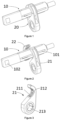
- Fig. 1 is a three-dimensional schematic drawing of a speed sensor in a preferred embodiment of the present invention
- Fig. 2 is an exploded schematic drawing of the speed sensor in a preferred embodiment of the present invention.
- a speed sensor comprising a sensor detection part 10 and a flange 20.
- the sensor detection part 10 is constructed as an independent component, formed by a resin or plastic material from a chip and an insertion pin, etc. by an injection molding process.
- the flange 20 comprises a first flange segment 21 and a second flange segment 22. As shown in Fig.
- the first flange segment 21 and second flange segment 22 are constructed as two separate and independent components; alternatively, in other embodiments, the first flange segment 21 and second flange segment 22 may also be constructed as conjoined components, partially connected to each other and hinged such that the two segments are able to move relative to each other.
- the first flange segment 21 and second flange segment 22 form the flange 20; moreover, once combined, the first flange segment 21 and second flange segment 22 enclose an accommodating hole capable of accommodating the sensor detection part 10.
- the sensor detection part 10 When assembly is performed, the sensor detection part 10 is able to move axially and rotate circumferentially in the accommodating hole of the flange 20, to adjust an axial distance and circumferential phase angle of a head sensing face 102 of the sensor detection part 10 relative to the flange 20.
- Fig. 3 is a schematic drawing of the first flange segment in a preferred embodiment of the present invention
- Fig. 4 is a schematic drawing of the second flange segment in a preferred embodiment of the present invention.
- weld fusion lines 211 are provided on the first flange segment 21, specifically on an accommodating hole surface in contact with the sensor detection part 10; preferably, there are three weld fusion lines 211, spaced apart parallel to each other.
- the first flange segment 21 is also provided with an installation hole 213 for a fixing bolt to pass through.
- Weld fusion lines 221 are also provided on the second flange segment 22, specifically on an accommodating hole surface in contact with the sensor detection part 10 and on surfaces in contact with the first flange segment 21; preferably, there are three weld fusion lines 211, spaced apart parallel to each other.
- the weld fusion lines 211, 221 can change to a molten state when heated by a fusion welding process, in particular by ultrasonic welding, etc.
- multiple positioning ribs 101 are provided on an outer wall of the sensor detection part 10; the multiple positioning ribs 101 extend in the direction of extension of the sensor detection part 10.
- Multiple slots 212, 222 are respectively provided in accommodating hole inner walls of the first flange segment 21 and second flange segment 22 that are in contact with the sensor detection part 10. These slots 212, 222 can accommodate the multiple positioning ribs 101 on the sensor detection part 10.
- the number of slots 212, 222 is no fewer than the number of positioning ribs 101, so that all of the positioning ribs 101 can be accommodated in the slots 212, 222.
- the slots 212, 222 and the positioning ribs 101 are provided in equal numbers, and are distributed uniformly in the circumferential direction.
- the positioning ribs 101 of the sensor detection part 10 can slide in the slots 212, 222, in order to adjust the axial distance between the head sensing face 102 of the sensor detection part 10 and the flange 20; and the slots 212, 222 can apply a circumferential positioning action to the positioning ribs 101, in order to keep the sensor detection part 10 at a predetermined circumferential angle relative to the flange 20.
- a manufacturing method for manufacturing the speed sensor described above is also provided.
- the manufacturing method comprises at least the following steps:
Landscapes
- Physics & Mathematics (AREA)
- General Physics & Mathematics (AREA)
- Engineering & Computer Science (AREA)
- Aviation & Aerospace Engineering (AREA)
- Transmission And Conversion Of Sensor Element Output (AREA)
- Injection Moulding Of Plastics Or The Like (AREA)
Abstract
Description
- The present invention relates to the technical field of detection, in particular to a speed sensor and a manufacturing method therefor.
- An existing speed sensor is injected molded from resin, to meet actual installation requirements. Once the speed sensor has been manufactured, the height of the sensing face of the head thereof (i.e. the detecting end of the sensor detection part) above the flange and the phase angle are both fixed values, which cannot be adjusted. To match different customers' installation requirements in different operating conditions, it is necessary to design speed sensors with different structures, and develop different molds to manufacture these speed sensors with different structures. Clearly, this consumes a considerable amount of manpower and resources. Some customers have quite similar installation requirements, but two different molds need to be developed to design similar sensor structures, which also causes wastage of resources. Furthermore, new products have a long mold development cycle, and a considerable amount of testing verification is subsequently needed; clearly, this cannot meet customers' time requirements either. Thus, there is a problem in urgent need of a solution in the art: how to achieve the standardization, flexibilization and universalization of speed sensors, and reduce the development cycle and costs.
- To overcome the shortcomings in the prior art, the present invention provides a speed sensor and a manufacturing method therefor, which achieve the standardization and universalization of speed sensor manufacturing, and enable flexible assembly according to different requirements, thus greatly reducing the development cycle and manufacturing costs.
- To achieve the above objective, the present invention provides a speed sensor, comprising a sensor detection part and a flange, wherein the flange comprises a first flange segment and a second flange segment, the flange is formed by combining the first flange segment and second flange segment, and once combined, the first flange segment and second flange segment together enclose an accommodating hole capable of accommodating the sensor detection part.
- Preferably, each pair of the sensor detection part, the first flange segment and the second flange segment is fixedly connected together.
- Preferably, the first flange segment and second flange segment are constructed as two separate and independent components.
- Preferably, the first flange segment and second flange segment are constructed as conjoined components, partially connected to each other and hinged such that the two segments are able to move relative to each other.
- Preferably, each pair of the sensor detection part, the first flange segment and the second flange segment is fixed together by ultrasonic welding.
- Preferably, weld fusion lines are provided on contact surfaces of the first flange segment and second flange segment.
- Preferably, multiple positioning ribs are provided on an outer wall of the sensor detection part, the positioning ribs extending in the direction of extension of the sensor detection part.
- Preferably, multiple slots are formed in an inner wall of the accommodating hole enclosed by the first flange segment and second flange segment, the slots being able to accommodate the positioning ribs.
- Preferably, the slots and the positioning ribs are provided in equal numbers, and are distributed uniformly in the circumferential direction.
- To achieve the abovementioned objective, the present invention further provides a manufacturing method for a speed sensor, the manufacturing method comprising at least the following steps:
- a step of separately manufacturing the sensor detection part, the first flange segment and the second flange segment;
- a step of fitting together the sensor detection part, the first flange segment and the second flange segment;
- a step of fixing together each pair of the sensor detection part, the first flange segment and the second flange segment.
- Preferably, the fixing step comprises a step of fixing together each pair of the sensor detection part, the first flange segment and the second flange segment by ultrasonic welding.
- Preferably, the step of fitting together comprises a step of assembly in accordance with preset values of axial distance and circumferential angle of the sensor detection part relative to the first flange segment and second flange segment.
- Compared with the prior art, the speed sensor and manufacturing method therefor of the present invention employ a split-body structure to manufacture a conventional speed sensor that is injection moulded in one piece. That is to say, the speed sensor is split into three constituent components, specifically the sensor detection part, the first flange segment and the second flange segment, and each of these constituent components can be produced in a standardized and universal way. Depending on customer requirements in different operating conditions, the required speed sensor can be obtained simply by fitting together the three constituent components according to different requirements and fixing them by fusion; thus, the flexibility of assembly of the three constituent components is higher. Thus, the technical solution of the present invention effectively avoids wastage of manpower and resources due to developing an excessive number of molds, increases production efficiency, lowers costs, and shortens the development cycle of new products.
-
-
Fig. 1 is a three-dimensional schematic drawing of a speed sensor in a preferred embodiment of the present invention. -
Fig. 2 is an exploded schematic drawing of the speed sensor in a preferred embodiment of the present invention. -
Fig. 3 is a schematic drawing of the first flange segment in a preferred embodiment of the present invention. -
Fig. 4 is a schematic drawing of the second flange segment in a preferred embodiment of the present invention. - The solution of the present invention will be further described below in conjunction with the drawings and preferred embodiments.
- Many details are given in the following description so that those skilled in the art can understand the invention more comprehensively. However, it will be obvious to those skilled in the art that the invention can be realized without some of these details. In addition, it should be understood that the invention is not limited to the specific embodiments described. On the contrary, one may consider using any combination of the following characteristics and elements to implement the invention, regardless of whether they relate to different embodiments. Therefore, the following aspects, characteristics, embodiments and advantages are only used to describe the invention, and should not be regarded as elements or definitions of the claims, unless expressly specified in the claims. In addition, terms indicating direction herein, such as up, down, left, right, upper side, lower side, etc., are merely based on the relative positions of components in the drawing concerned for the convenience of description, and should not be construed as limiting the scope of protection.
-
Fig. 1 is a three-dimensional schematic drawing of a speed sensor in a preferred embodiment of the present invention;Fig. 2 is an exploded schematic drawing of the speed sensor in a preferred embodiment of the present invention. - Referring to
Figs. 1 and 2 , in one embodiment of the present invention, a speed sensor is provided, comprising asensor detection part 10 and aflange 20. Thesensor detection part 10 is constructed as an independent component, formed by a resin or plastic material from a chip and an insertion pin, etc. by an injection molding process. Theflange 20 comprises afirst flange segment 21 and asecond flange segment 22. As shown inFig. 2 , thefirst flange segment 21 andsecond flange segment 22 are constructed as two separate and independent components; alternatively, in other embodiments, thefirst flange segment 21 andsecond flange segment 22 may also be constructed as conjoined components, partially connected to each other and hinged such that the two segments are able to move relative to each other. Once combined, thefirst flange segment 21 andsecond flange segment 22 form theflange 20; moreover, once combined, thefirst flange segment 21 andsecond flange segment 22 enclose an accommodating hole capable of accommodating thesensor detection part 10. When assembly is performed, thesensor detection part 10 is able to move axially and rotate circumferentially in the accommodating hole of theflange 20, to adjust an axial distance and circumferential phase angle of a head sensingface 102 of thesensor detection part 10 relative to theflange 20. -
Fig. 3 is a schematic drawing of the first flange segment in a preferred embodiment of the present invention;Fig. 4 is a schematic drawing of the second flange segment in a preferred embodiment of the present invention. - Referring to
Figs. 3 and4 ,weld fusion lines 211 are provided on thefirst flange segment 21, specifically on an accommodating hole surface in contact with thesensor detection part 10; preferably, there are threeweld fusion lines 211, spaced apart parallel to each other. Thefirst flange segment 21 is also provided with aninstallation hole 213 for a fixing bolt to pass through.Weld fusion lines 221 are also provided on thesecond flange segment 22, specifically on an accommodating hole surface in contact with thesensor detection part 10 and on surfaces in contact with thefirst flange segment 21; preferably, there are threeweld fusion lines 211, spaced apart parallel to each other. Theweld fusion lines sensor detection part 10, thefirst flange segment 21 and thesecond flange segment 22 have been fitted together, the weld fusion lines between the three components are heated to a molten state by fusion welding, such that gaps between each pair of the three components are filled by fusion line material in the molten state; once cooled, each pair of the three components is firmly fused together, finally forming a speed sensor that meets requirements. - Furthermore, as shown in
Fig. 2 ,multiple positioning ribs 101 are provided on an outer wall of thesensor detection part 10; themultiple positioning ribs 101 extend in the direction of extension of thesensor detection part 10.Multiple slots first flange segment 21 andsecond flange segment 22 that are in contact with thesensor detection part 10. Theseslots multiple positioning ribs 101 on thesensor detection part 10. The number ofslots positioning ribs 101, so that all of thepositioning ribs 101 can be accommodated in theslots slots positioning ribs 101 are provided in equal numbers, and are distributed uniformly in the circumferential direction. - When assembly is performed, the
positioning ribs 101 of thesensor detection part 10 can slide in theslots face 102 of thesensor detection part 10 and theflange 20; and theslots positioning ribs 101, in order to keep thesensor detection part 10 at a predetermined circumferential angle relative to theflange 20. - In an embodiment of the present invention, a manufacturing method for manufacturing the speed sensor described above is also provided.
- The manufacturing method comprises at least the following steps:
- A component pre-manufacturing step, in which three constituent components, specifically the
sensor detection part 10, thefirst flange segment 21 and thesecond flange segment 22, are separately manufactured. These three constituent components may be manufactured once or multiple times by mold injection molding or another process. - A component assembly step, in which the
sensor detection part 10, thefirst flange segment 21 and thesecond flange segment 22 are fitted together in accordance with requirements. When assembly is performed, the axial distance and circumferential phase angle of thesensor detection part 10 relative to thefirst flange segment 21 andsecond flange segment 22 are adjusted to preset values according to customer requirements. - A fixing step, in which the
sensor detection part 10, thefirst flange segment 21 and thesecond flange segment 22 are fixed together by fusion welding, e.g. ultrasonic welding, between each pair thereof. - Although the invention has been disclosed above with preferred embodiments, the invention is not limited to these. Any change or modification made by those skilled in the art without departing from the spirit and scope of the present invention should fall within the scope of protection of the invention. Therefore, the scope of protection of the invention should be the scope defined by the claims.
Claims (10)
- A speed sensor, comprising a sensor detection part and a flange, wherein the flange comprises a first flange segment and a second flange segment, the flange is formed by combining the first flange segment and second flange segment, and once combined, the first flange segment and second flange segment enclose an accommodating hole capable of accommodating the sensor detection part.
- The speed sensor as claimed in claim 1, wherein each pair of the sensor detection part, the first flange segment and the second flange segment is fixedly connected together.
- The speed sensor as claimed in claim 1, wherein the first flange segment and second flange segment are constructed as two separate and independent components.
- The speed sensor as claimed in claim 1, wherein the first flange segment and second flange segment are constructed as conjoined components, partially connected to each other and hinged such that the two segments are able to move relative to each other.
- The speed sensor as claimed in claim 2, wherein each pair of the sensor detection part, the first flange segment and the second flange segment is fixed together by ultrasonic welding.
- The speed sensor as claimed in any one of claims 1 - 5, wherein weld fusion lines are provided on contact surfaces of the first flange segment and second flange segment.
- The speed sensor as claimed in any one of claims 1 - 5, wherein multiple positioning ribs are provided on an outer wall of the sensor detection part, the positioning ribs extending in the direction of extension of the sensor detection part.
- The speed sensor as claimed in claim 7, wherein multiple slots are formed in an inner wall of the accommodating hole enclosed by the first flange segment and second flange segment, the slots being able to accommodate the positioning ribs.
- The speed sensor as claimed in claim 8, wherein the slots and the positioning ribs are provided in equal numbers, and are distributed uniformly in the circumferential direction.
- A manufacturing method for a speed sensor, wherein the speed sensor is the speed sensor as claimed in any one of claims 1 - 9, and the manufacturing method comprises at least the following steps:a step of separately manufacturing the sensor detection part, the first flange segment and the second flange segment;a step of fitting together the sensor detection part, the first flange segment and the second flange segment;a step of fixing together each pair of the sensor detection part, the first flange segment and the second flange segment.
Applications Claiming Priority (1)
| Application Number | Priority Date | Filing Date | Title |
|---|---|---|---|
| CN202111603914.3A CN116338228A (en) | 2021-12-24 | 2021-12-24 | A speed sensor and its manufacturing method |
Publications (1)
| Publication Number | Publication Date |
|---|---|
| EP4202446A1 true EP4202446A1 (en) | 2023-06-28 |
Family
ID=84569764
Family Applications (1)
| Application Number | Title | Priority Date | Filing Date |
|---|---|---|---|
| EP22215861.0A Pending EP4202446A1 (en) | 2021-12-24 | 2022-12-22 | Speed sensor and manufacturing method therefor |
Country Status (2)
| Country | Link |
|---|---|
| EP (1) | EP4202446A1 (en) |
| CN (1) | CN116338228A (en) |
Citations (6)
| Publication number | Priority date | Publication date | Assignee | Title |
|---|---|---|---|---|
| JP2010008329A (en) * | 2008-06-30 | 2010-01-14 | Bosch Corp | Sensor with mounting mechanism using seal ring and its mounting structure |
| US20160327416A1 (en) * | 2014-01-17 | 2016-11-10 | Alphinity, Llc | Fluid monitoring assembly with sensor functionality |
| EP3301342A1 (en) * | 2016-10-03 | 2018-04-04 | Pool Technologie | Instrument-holder for pipe and associated apparatus |
| CN211086335U (en) * | 2019-11-13 | 2020-07-24 | 大陆汽车电子(连云港)有限公司 | a wheel speed sensor |
| EP3848255A1 (en) * | 2020-01-08 | 2021-07-14 | Illinois Tool Works Inc. | Sensor housing for a sensor for detecting acceleration and / or tilt angle changes and sensor comprising such a sensor housing |
| WO2023277566A1 (en) * | 2021-06-30 | 2023-01-05 | 주식회사 만도 | Wheel speed sensing device |
Family Cites Families (5)
| Publication number | Priority date | Publication date | Assignee | Title |
|---|---|---|---|---|
| KR200286153Y1 (en) * | 1998-10-22 | 2002-11-18 | 주식회사 만도 | Flange fixing device for vehicle wheel speed sensor |
| KR101363217B1 (en) * | 2011-12-15 | 2014-02-14 | 대성전기공업 주식회사 | Wheel Speed Sensor for Vehicle |
| CN204341007U (en) * | 2014-12-02 | 2015-05-20 | 北汽福田汽车股份有限公司 | Wheel speed sensors assembly and wheel speed sensors assembly erecting device |
| DE102017007399A1 (en) * | 2017-08-04 | 2019-02-07 | Wabco Gmbh | Speed sensor for a vehicle, in particular a commercial vehicle, and a method for its production |
| JP2021173725A (en) * | 2020-04-30 | 2021-11-01 | 住友金属鉱山株式会社 | Rotating body for speed sensor |
-
2021
- 2021-12-24 CN CN202111603914.3A patent/CN116338228A/en active Pending
-
2022
- 2022-12-22 EP EP22215861.0A patent/EP4202446A1/en active Pending
Patent Citations (6)
| Publication number | Priority date | Publication date | Assignee | Title |
|---|---|---|---|---|
| JP2010008329A (en) * | 2008-06-30 | 2010-01-14 | Bosch Corp | Sensor with mounting mechanism using seal ring and its mounting structure |
| US20160327416A1 (en) * | 2014-01-17 | 2016-11-10 | Alphinity, Llc | Fluid monitoring assembly with sensor functionality |
| EP3301342A1 (en) * | 2016-10-03 | 2018-04-04 | Pool Technologie | Instrument-holder for pipe and associated apparatus |
| CN211086335U (en) * | 2019-11-13 | 2020-07-24 | 大陆汽车电子(连云港)有限公司 | a wheel speed sensor |
| EP3848255A1 (en) * | 2020-01-08 | 2021-07-14 | Illinois Tool Works Inc. | Sensor housing for a sensor for detecting acceleration and / or tilt angle changes and sensor comprising such a sensor housing |
| WO2023277566A1 (en) * | 2021-06-30 | 2023-01-05 | 주식회사 만도 | Wheel speed sensing device |
Also Published As
| Publication number | Publication date |
|---|---|
| CN116338228A (en) | 2023-06-27 |
Similar Documents
| Publication | Publication Date | Title |
|---|---|---|
| JP6029319B2 (en) | Plastic optical member, method of manufacturing plastic optical member, and lens | |
| US20210057957A1 (en) | One body type terminal assembly of driving motor for vehicle and manufacturing method thereof | |
| JP6028743B2 (en) | Resin spacer, insert molded product, and manufacturing method thereof | |
| US20150042003A1 (en) | Method for injection molding of thermoplastic pole parts, and mold for producing the same | |
| CN102322965B (en) | Temperature sensor and packaging equipment and packaging method thereof | |
| JP5930309B2 (en) | Rotation detecting device and manufacturing method thereof | |
| CN105228807A (en) | The mould of temperature sensor manufacture, manufacture method and temperature sensor | |
| US9897395B2 (en) | Tank for heat exchanger, and method for manufacturing the same | |
| US20120094045A1 (en) | Resin molding apparatus, process for manufacturing resin molded product, hollow molded product and container | |
| JP5507419B2 (en) | Method for molding hollow resin molding | |
| US10139254B2 (en) | Method for manufacturing a measurement sensor for a motor vehicle | |
| WO2021039026A1 (en) | Insulator and motor | |
| CN103226152B (en) | Rotation detection device and manufacturing method thereof | |
| JP2015124845A (en) | Pipe-like molded body and its process of manufacture | |
| JP6671123B2 (en) | Reel member, film container, and method of manufacturing reel member | |
| JP2012121157A (en) | Molding apparatus and molding method | |
| CN116338228A (en) | A speed sensor and its manufacturing method | |
| CN102756454B (en) | The manufacture method of resin-seal molding product | |
| JP7088681B2 (en) | Manufacturing method of molded product | |
| JP2014240689A (en) | Pipe-like molding and method of manufacturing the same | |
| JP2011218700A (en) | Method of molding hollow molded article, and hollow molded article | |
| JP2021079586A (en) | Lens holder molding mold | |
| JP2018109658A (en) | Plastic optical member and manufacturing method therefor | |
| CN102751061A (en) | Thermistor packaging technology | |
| KR101937357B1 (en) | Mold of vehicle clutch housing for diecasting and manufacturing method of vehicle clutch housing |
Legal Events
| Date | Code | Title | Description |
|---|---|---|---|
| PUAI | Public reference made under article 153(3) epc to a published international application that has entered the european phase |
Free format text: ORIGINAL CODE: 0009012 |
|
| STAA | Information on the status of an ep patent application or granted ep patent |
Free format text: STATUS: THE APPLICATION HAS BEEN PUBLISHED |
|
| AK | Designated contracting states |
Kind code of ref document: A1 Designated state(s): AL AT BE BG CH CY CZ DE DK EE ES FI FR GB GR HR HU IE IS IT LI LT LU LV MC ME MK MT NL NO PL PT RO RS SE SI SK SM TR |
|
| STAA | Information on the status of an ep patent application or granted ep patent |
Free format text: STATUS: REQUEST FOR EXAMINATION WAS MADE |
|
| 17P | Request for examination filed |
Effective date: 20240102 |
|
| RBV | Designated contracting states (corrected) |
Designated state(s): AL AT BE BG CH CY CZ DE DK EE ES FI FR GB GR HR HU IE IS IT LI LT LU LV MC ME MK MT NL NO PL PT RO RS SE SI SK SM TR |
|
| RAP3 | Party data changed (applicant data changed or rights of an application transferred) |
Owner name: CONTINENTAL AUTOMOTIVE TECHNOLOGIES GMBH |
|
| STAA | Information on the status of an ep patent application or granted ep patent |
Free format text: STATUS: EXAMINATION IS IN PROGRESS |
|
| 17Q | First examination report despatched |
Effective date: 20250219 |
|
| RAP3 | Party data changed (applicant data changed or rights of an application transferred) |
Owner name: AUMOVIO GERMANY GMBH |