EP4202196B1 - System und verfahren zur verhinderung von vereisung im verbrennungseinlassluftweg einer gasturbinenanlage - Google Patents
System und verfahren zur verhinderung von vereisung im verbrennungseinlassluftweg einer gasturbinenanlage Download PDFInfo
- Publication number
- EP4202196B1 EP4202196B1 EP22211615.4A EP22211615A EP4202196B1 EP 4202196 B1 EP4202196 B1 EP 4202196B1 EP 22211615 A EP22211615 A EP 22211615A EP 4202196 B1 EP4202196 B1 EP 4202196B1
- Authority
- EP
- European Patent Office
- Prior art keywords
- air
- inlet
- gas turbine
- turbine engine
- combustion
- Prior art date
- Legal status (The legal status is an assumption and is not a legal conclusion. Google has not performed a legal analysis and makes no representation as to the accuracy of the status listed.)
- Active
Links
Images

Classifications
-
- F—MECHANICAL ENGINEERING; LIGHTING; HEATING; WEAPONS; BLASTING
- F02—COMBUSTION ENGINES; HOT-GAS OR COMBUSTION-PRODUCT ENGINE PLANTS
- F02C—GAS-TURBINE PLANTS; AIR INTAKES FOR JET-PROPULSION PLANTS; CONTROLLING FUEL SUPPLY IN AIR-BREATHING JET-PROPULSION PLANTS
- F02C7/00—Features, components parts, details or accessories, not provided for in, or of interest apart form groups F02C1/00 - F02C6/00; Air intakes for jet-propulsion plants
- F02C7/04—Air intakes for gas-turbine plants or jet-propulsion plants
- F02C7/047—Heating to prevent icing
-
- F—MECHANICAL ENGINEERING; LIGHTING; HEATING; WEAPONS; BLASTING
- F01—MACHINES OR ENGINES IN GENERAL; ENGINE PLANTS IN GENERAL; STEAM ENGINES
- F01D—NON-POSITIVE DISPLACEMENT MACHINES OR ENGINES, e.g. STEAM TURBINES
- F01D21/00—Shutting-down of machines or engines, e.g. in emergency; Regulating, controlling, or safety means not otherwise provided for
- F01D21/003—Arrangements for testing or measuring
-
- F—MECHANICAL ENGINEERING; LIGHTING; HEATING; WEAPONS; BLASTING
- F02—COMBUSTION ENGINES; HOT-GAS OR COMBUSTION-PRODUCT ENGINE PLANTS
- F02C—GAS-TURBINE PLANTS; AIR INTAKES FOR JET-PROPULSION PLANTS; CONTROLLING FUEL SUPPLY IN AIR-BREATHING JET-PROPULSION PLANTS
- F02C7/00—Features, components parts, details or accessories, not provided for in, or of interest apart form groups F02C1/00 - F02C6/00; Air intakes for jet-propulsion plants
- F02C7/04—Air intakes for gas-turbine plants or jet-propulsion plants
- F02C7/045—Air intakes for gas-turbine plants or jet-propulsion plants having provisions for noise suppression
-
- F—MECHANICAL ENGINEERING; LIGHTING; HEATING; WEAPONS; BLASTING
- F02—COMBUSTION ENGINES; HOT-GAS OR COMBUSTION-PRODUCT ENGINE PLANTS
- F02C—GAS-TURBINE PLANTS; AIR INTAKES FOR JET-PROPULSION PLANTS; CONTROLLING FUEL SUPPLY IN AIR-BREATHING JET-PROPULSION PLANTS
- F02C7/00—Features, components parts, details or accessories, not provided for in, or of interest apart form groups F02C1/00 - F02C6/00; Air intakes for jet-propulsion plants
- F02C7/04—Air intakes for gas-turbine plants or jet-propulsion plants
- F02C7/05—Air intakes for gas-turbine plants or jet-propulsion plants having provisions for obviating the penetration of damaging objects or particles
- F02C7/052—Air intakes for gas-turbine plants or jet-propulsion plants having provisions for obviating the penetration of damaging objects or particles with dust-separation devices
-
- F—MECHANICAL ENGINEERING; LIGHTING; HEATING; WEAPONS; BLASTING
- F02—COMBUSTION ENGINES; HOT-GAS OR COMBUSTION-PRODUCT ENGINE PLANTS
- F02C—GAS-TURBINE PLANTS; AIR INTAKES FOR JET-PROPULSION PLANTS; CONTROLLING FUEL SUPPLY IN AIR-BREATHING JET-PROPULSION PLANTS
- F02C7/00—Features, components parts, details or accessories, not provided for in, or of interest apart form groups F02C1/00 - F02C6/00; Air intakes for jet-propulsion plants
- F02C7/04—Air intakes for gas-turbine plants or jet-propulsion plants
- F02C7/05—Air intakes for gas-turbine plants or jet-propulsion plants having provisions for obviating the penetration of damaging objects or particles
- F02C7/055—Air intakes for gas-turbine plants or jet-propulsion plants having provisions for obviating the penetration of damaging objects or particles with intake grids, screens or guards
-
- F—MECHANICAL ENGINEERING; LIGHTING; HEATING; WEAPONS; BLASTING
- F02—COMBUSTION ENGINES; HOT-GAS OR COMBUSTION-PRODUCT ENGINE PLANTS
- F02C—GAS-TURBINE PLANTS; AIR INTAKES FOR JET-PROPULSION PLANTS; CONTROLLING FUEL SUPPLY IN AIR-BREATHING JET-PROPULSION PLANTS
- F02C9/00—Controlling gas-turbine plants; Controlling fuel supply in air- breathing jet-propulsion plants
- F02C9/26—Control of fuel supply
- F02C9/28—Regulating systems responsive to plant or ambient parameters, e.g. temperature, pressure, rotor speed
-
- F—MECHANICAL ENGINEERING; LIGHTING; HEATING; WEAPONS; BLASTING
- F05—INDEXING SCHEMES RELATING TO ENGINES OR PUMPS IN VARIOUS SUBCLASSES OF CLASSES F01-F04
- F05D—INDEXING SCHEME FOR ASPECTS RELATING TO NON-POSITIVE-DISPLACEMENT MACHINES OR ENGINES, GAS-TURBINES OR JET-PROPULSION PLANTS
- F05D2220/00—Application
- F05D2220/30—Application in turbines
- F05D2220/32—Application in turbines in gas turbines
-
- F—MECHANICAL ENGINEERING; LIGHTING; HEATING; WEAPONS; BLASTING
- F05—INDEXING SCHEMES RELATING TO ENGINES OR PUMPS IN VARIOUS SUBCLASSES OF CLASSES F01-F04
- F05D—INDEXING SCHEME FOR ASPECTS RELATING TO NON-POSITIVE-DISPLACEMENT MACHINES OR ENGINES, GAS-TURBINES OR JET-PROPULSION PLANTS
- F05D2230/00—Manufacture
- F05D2230/90—Coating; Surface treatment
-
- F—MECHANICAL ENGINEERING; LIGHTING; HEATING; WEAPONS; BLASTING
- F05—INDEXING SCHEMES RELATING TO ENGINES OR PUMPS IN VARIOUS SUBCLASSES OF CLASSES F01-F04
- F05D—INDEXING SCHEME FOR ASPECTS RELATING TO NON-POSITIVE-DISPLACEMENT MACHINES OR ENGINES, GAS-TURBINES OR JET-PROPULSION PLANTS
- F05D2240/00—Components
- F05D2240/10—Stators
- F05D2240/14—Casings or housings protecting or supporting assemblies within
-
- F—MECHANICAL ENGINEERING; LIGHTING; HEATING; WEAPONS; BLASTING
- F05—INDEXING SCHEMES RELATING TO ENGINES OR PUMPS IN VARIOUS SUBCLASSES OF CLASSES F01-F04
- F05D—INDEXING SCHEME FOR ASPECTS RELATING TO NON-POSITIVE-DISPLACEMENT MACHINES OR ENGINES, GAS-TURBINES OR JET-PROPULSION PLANTS
- F05D2260/00—Function
- F05D2260/60—Fluid transfer
- F05D2260/607—Preventing clogging or obstruction of flow paths by dirt, dust, or foreign particles
-
- F—MECHANICAL ENGINEERING; LIGHTING; HEATING; WEAPONS; BLASTING
- F05—INDEXING SCHEMES RELATING TO ENGINES OR PUMPS IN VARIOUS SUBCLASSES OF CLASSES F01-F04
- F05D—INDEXING SCHEME FOR ASPECTS RELATING TO NON-POSITIVE-DISPLACEMENT MACHINES OR ENGINES, GAS-TURBINES OR JET-PROPULSION PLANTS
- F05D2300/00—Materials; Properties thereof
- F05D2300/50—Intrinsic material properties or characteristics
- F05D2300/512—Hydrophobic, i.e. being or having non-wettable properties
Definitions
- Embodiments of this disclosure relate generally to gas turbine systems, and more specifically, to a system and method for preventing icing in the combustion inlet air path of a gas turbine system.
- Gas turbine engines are utilized globally for electric power generation or as mechanical drives for operating equipment under a variety of climatic conditions. Operation during cold ambient temperature and high humidity conditions can lead to icing problems in gas turbine systems in which gas turbine engines are utilized. For example, ice can plug the filtration system of an air intake system to a gas turbine engine causing a significant drop in pressure in the air intake system, which in turn, leads to performance loss (e.g., gas turbine power output deterioration). In extreme cases, there is even a possibility that ice pieces can get ingested into a first blade stage of a compressor in the gas turbine engine, which can cause damage and may lead to some blades becoming inoperable.
- performance loss e.g., gas turbine power output deterioration
- Ice may also cause the disruption of compressor work because of excessive vibration, or surging by decreasing the inlet flow, all of which can reduce the operational efficiency of the gas turbine system. Consequently, gas turbine systems that are located in cold weather locations where icing conditions can exist are typically equipped with anti-icing systems that can heat the intake air before it enters the compressor of the gas turbine engine. These anti-icing systems, which can include inlet heating coils, can be costly to implement.
- US 9 200 568 B1 discloses a gas turbine system comprising a gas turbine engine, an air intake system to intake air for supply to the gas turbine engine, the air intake system comprising an air filter inlet house to filter the intake air, wherein the air filter inlet house includes at least one filter stage having an array of pulse filters, with each of the pulse filters being hydrophobic, and a combustion inlet air path in fluid communication with the air intake system and the gas turbine engine, the combustion inlet air path receiving the filtered air from the air filter inlet house and supplying the filtered air as combustion inlet air to an inlet of the gas turbine engine.
- US 2006/281861 A1 suggests to apply erosion resistant icephobic coatings on various gas turbine engine components, such as stators, inlets, nose cones, fan blades, leading edge structures, etc., to provide lower ice adhesion strengths and better erosion resistance, should the need arise.
- US 2016/061158 A1 discloses a filter media comprising a hydrophobic media layer for use e.g. in a filtration system for a gas turbine engine.
- US 7 632 339 B2 discloses a moisture removal system and method for a gas turbine system and suggests to provide a hydrophobic coating on weather hoods at the air inlet of the gas turbine system and use hydrophobic filter materials or fibers in primary filters in the air duct downstream of the air inlet.
- the various embodiments of the present invention are directed to providing a novel and nonobvious anti-icing approach for use with a gas turbine system utilizing a gas turbine engine without having to rely on an anti-icing system to heat the intake air.
- the solution provided by the various embodiments includes utilizing an array of hydrophobic pulse filters in the air filter inlet house of an air intake system to a gas turbine engine, along with at least one component in the combustion inlet air path between the air filter inlet house and the inlet of the gas turbine engine that has a surface with an anti-icing coating to prevent ice from forming.
- a pulse filter controller can be programmed to pulse the pulse filters to dislodge ice from the filters as conditions dictate.
- pulse filters that are hydrophobic blocks liquid water from passing through to the combustion inlet air path and into the inlet of the gas turbine engine. Blocking liquid water from passing through to the combustion inlet air path prevents ice accretion on the components in the path that can arise in cold weather conditions.
- icing conditions can still develop due to humidity that moves through the combustion inlet air path. Operation during cold ambient temperatures and high humidity are conditions that can lead to icing problems in gas turbine systems in which gas turbine engines are utilized.
- icing conditions can develop on components in the combustion inlet air path when ambient operating conditions include at least 70% humidity and a temperature that is below 4,4°C (40 degrees Fahrenheit (F)). Applying an anti-icing coating to at least one component in the combustion inlet air path prevents ice from forming when operating conditions include at least 70% humidity and a temperature that is below 4,4°C (40 degrees F).
- a foreign object damage (FOD) screen is one component in the combustion inlet air path between the air filter inlet house and the inlet of the gas turbine engine that has an anti-icing coating.
- a FOD screen which collectively includes one or more screens and an air sock, is used to protect the gas turbine engine from debris (e.g., weld slag) that could lead to damage (e.g., blade damage) if allowed to pass through into the gas turbine engine.
- the FOD screen which is placed upstream of the inlet of the gas turbine engine, provides "last chance” protection against foreign object damage to the gas turbine engine. Icing conditions (i.e., at least 70% humidity and a temperature that is below 4,4°C (40 degrees F)) can lead to ice formation on the FOD screen.
- Ice on the FOD screen can lead to a differential pressure across the FOD screen. As differential pressure increases across the FOD screen, it reduces the air flow going through the gas turbine engine. This can affect turbine operation due to icing build up in the FOD screen. This icing build up in the FOD screen can eventually cause the turbine to shut down. Applying the anti-icing coating to the FOD screen transforms the screen to an icephobic FOD screen that inhibits the formation of ice that can lead to damage of the gas turbine engine and possible shut down of the turbine.
- Other components in or upstream of the combustion inlet air path between the air filter inlet house and the inlet of the gas turbine engine can also have an anti-icing coating applied to a surface to prevent the formation of ice.
- These other components can include, but are not limited to, weather hoods mounted on the air filter inlet house that permit passage of a stream of inlet air and prevent weather elements from entering, the silencer that is used to reduce the "noise" associated with the stream of the combustion inlet air transmitted to the inlet of the gas turbine engine, the inlet plenum and inlet volute that supply the combustion inlet air to the inlet of the gas turbine engine, the inlet guide vanes that direct the combustion inlet air to the inlet of the gas turbine engine, and the inlet struts that support the combustion inlet air duct that supplies the combustion inlet air towards the inlet of the gas turbine engine. Applying an anti-icing coating to one or more of these components can complement the anti-icing coating applied to the FOD screen.
- the configuration of the array of hydrophobic pulse filters along with at least one component in the combustion inlet air path between the air filter inlet house and the inlet of the gas turbine engine that has a surface with an anti-icing coating allows the various embodiments of the present invention to eliminate the possibility of ice accretion in the combustion inlet duct. This allows the gas turbine engine to operate continuously during icing conditions.
- the configuration of the various embodiments obviates the need to utilize an anti-icing system to heat the intake air, thereby maximizing efficiency and cost effectiveness of the gas turbine system.
- the configuration of the various embodiments is suitable for use with gas turbine systems that are already implemented with an anti-icing system. To this extent, the configuration of the various embodiments can be utilized to avoid parasitic loads that are associated with the use of these anti-icing systems.
- a gas turbine system comprises: a gas turbine engine; an air intake system to intake air for supply to the gas turbine engine, the air intake system comprising an air filter inlet house to filter the intake air, wherein the air filter inlet house includes at least one filter stage having an array of pulse filters, with each of the pulse filters being hydrophobic, a combustion inlet air path in fluid communication with the air intake system and the gas turbine engine, the combustion inlet air path receiving the filtered air from the air filter inlet house and supplying the filtered air as combustion inlet air to an inlet of the gas turbine engine; and a foreign object damage (FOD) screen in the combustion inlet air path between the air filter inlet house and the inlet of the gas turbine engine to prevent debris from entering the inlet of the gas turbine engine, wherein the FOD screen includes one or more mesh screens and an air sock placed over the one or more mesh screens, the one or more mesh screens enclosed in a frame structure having horizontally and vertically extending rails defining
- a method for preventing icing in the combustion inlet air path of a gas turbine system having a gas turbine engine, an air intake system to intake air for supply to the gas turbine engine, and a combustion inlet air path to supply combustion inlet air to an inlet of the gas turbine engine is provided.
- the method comprises: filtering the intake air in the air intake system with an air filter inlet house including at least one filter stage having an array of hydrophobic pulse filters; supplying the filtered air as combustion inlet air to the inlet of the gas turbine engine; and applying an anti-icing coating to a surface of at least one component in a path of the combustion inlet air between the air filter inlet house and the inlet of the gas turbine engine to prevent ice from forming on the at least component.
- the at least one component comprises a foreign object damage (FOD) screen, wherein the FOD screen includes one or more mesh screens and an air sock placed over the one or more mesh screens.
- FOD foreign object damage
- the one or more mesh screens are enclosed in a frame structure having horizontally and vertically extending rails defining individual segments of sub-frame structures formed by intersections of the horizontally extending rails with the vertically extending rails, each individual segment of sub-frame structures enclosing portions of the one or more mesh screens, wherein a surface of each of the one or more mesh screens in the individual segments of sub-frame structures and the air sock placed over the one or more screens comprises the anti-icing coating to prevent ice formation thereon.
- the anti-icing coating is applied to each of the one or more mesh screens in the individual segments of sub-frame structures and the air sock in locations where there is direct particle impact with particles flowing through the combustion inlet air path and locations without direct particle impact with the particles flowing through the combustion inlet air path.
- This disclosure relates generally to gas turbine systems, and more specifically, to a system and method for preventing icing in the combustion inlet air path of a gas turbine system.
- the combustion inlet air path of a gas turbine system extends from the ambient air at the air intake system of the gas turbine system to the first stage of the gas turbine compressor.
- the various embodiments of the present invention prevent the formation of ice in the combustion inlet air path of a gas turbine system through the use of an array of hydrophobic pulse filters in the air filter inlet house of an air intake system to a gas turbine engine, along with at least one component in the combustion inlet air path between the air filter inlet house and the inlet of the gas turbine engine that has a surface with an anti-icing or icephobic coating to prevent ice from forming on the at least one component.
- the prevention of the formation of ice in the combustion inlet air path of a gas turbine system as described in the various embodiments is suitable for use with all types of gas turbine systems and gas turbine combustion systems utilizing turbomachinery regardless of their application (e.g., land-based, marine-based, and aviation based applications).
- Gas turbine systems and gas turbine combustion systems using turbomachines that include, but are not limited to, heavy frame industrial gas turbines, aeroderivative gas turbines, marine gas turbines, ammonia-fueled gas turbines, hydrogen-fueled gas turbines, aviation gas turbines, and general combustion turbines are non-limiting examples of systems that can have a need to prevent ice formation in the combustion inlet air path if deployed in cold weather locations, and thus, are applicable for use with the various embodiments.
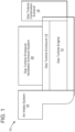
- FIG. 1 shows a schematic block diagram of a gas turbine system 10 in which a system for preventing icing in the combustion inlet air path of the gas turbine system can be implemented according to an embodiment of the invention.
- the gas turbine system 10 includes a gas turbine engine 12, a gas turbine enclosure 14 that houses the gas turbine engine 12, an air intake system 16 that provides filtered air to the gas turbine engine 12 for combustion, a gas turbine combustion exhaust 18 for releasing exhaust gases from the gas turbine engine 12, and a gas turbine enclosure ventilation exhaust system 20 to purge and ventilate heat and exhaust products from the gas turbine engine 12.
- the gas turbine engine 12 can include a compressor, a combustor, and a turbine.
- the compressor can compress an incoming flow of air.
- the compressor can deliver the compressed flow of air to the combustor, where the compressed flow of air mixes with a compressed flow of fuel.
- the combustor can ignite the air/fuel mixture to create a flow of combustion gases.
- the flow of combustion gases can be delivered to the turbine to drive the turbine to produce mechanical work.
- the mechanical work produced in the turbine can drive the compressor and an external load, such as an electrical generator or the like.
- the flow of combustion gases may be exhausted or otherwise disposed by the gas turbine combustion exhaust 18.
- the gas turbine engine 12 can use natural gas, various types of syngas, and/or other types of fuels.
- the gas turbine engine 12 may be any one of a number of different gas turbine engines such as those offered by the General Electric Company.
- the gas turbine enclosure 14 which encloses the gas turbine engine 12, can isolate the gas turbine engine.
- the gas turbine enclosure 14 can include a number of different components that operate in conjunction with the gas turbine engine 12.
- the gas turbine enclosure 14 can include piping for lube oil, NOx emissions, power augmentation, and the like.
- Other components can include, but are not limited to, a gas detection system and a fire detection and suppression system.
- the gas turbine enclosure 14 can perform a number of different functions that contribute to the operation of the gas turbine engine 12.
- the gas turbine enclosure 14 can serve as a sump for oil leaks from the gas turbine engine 12.
- the air intake system 16 can include an inlet screen or an air filter inlet house that includes one or more filter assemblies having a number of inlet air filters that remove moisture and/or particulate matter (such as dust, dirt, contaminants and/or debris) from intake air channeled for supply to the gas turbine engine 12.
- a clean air duct can receive the filtered air from the air filter inlet house.
- the air in the clean air duct can be divided into combustion inlet air that goes to the compressor of the gas turbine engine 12, and ventilation inlet air that is supplied to the gas turbine enclosure 14.
- a combustion inlet air duct can provide the combustion inlet air to the compressor, while a ventilation inlet air bypass conduit can supply the ventilation inlet air to the gas turbine enclosure 14.
- the gas turbine enclosure ventilation exhaust system 20 can include one or more ventilation fans that operate to generate an air flow to purge the gas turbine enclosure 14 of heat and exhaust products from the gas turbine engine 12.
- the gas turbine enclosure ventilation exhaust system 20 can include a damper that controls the flow of air containing the heat and exhaust products from the gas turbine engine 12 and the gas turbine enclosure 14.
- the gas turbine system 10 can include a number of other components not depicted in FIG. 1 .
- the gas turbine system 10 can include a shaft operatively coupled to the compressor and turbine of the gas turbine engine 12.
- the shaft may be connected to an electrical generator for power generation applications.
- the gas turbine system 10 depicted in FIG. 1 can take the form of an aeroderivative gas turbine system.
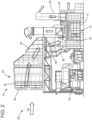
- FIG. 2 shows a schematic example of an aeroderivative gas turbine system 22, of which the system for preventing icing in the combustion inlet air path described herein can be implemented according to an embodiment of the invention.
- downstream and upstream are terms that indicate a direction relative to the flow of a fluid, such as the working fluid through the gas turbine system, for example, the flow of air through the air intake system or through one of the components of a gas turbine engine.
- the term “downstream” corresponds to the direction of flow of the fluid
- upstream refers to the direction opposite to the flow.
- the aeroderivative gas turbine system 22 of FIG. 2 shows the air intake system 16 having an air filter inlet house 24.
- the air intake system 16 can further include a weather hood 26 mounted on the air filter inlet house 24 that permits passage of a stream of inlet air 28 and prevents weather elements such as rain, snow, and the like from entering therein.
- the weather hood 26 may be largely of conventional design, and can include a plurality of inlet vane type separators and moisture separators to prevent heavy rain or heavy fog mist from entering the air filter inlet house 24.
- the inlet vane type separators can remove water droplet particles larger than a specified size (e.g., 5 microns in size) to prevent liquid droplets from carrying any absorbed salt downstream into the gas turbine engine 14.
- the moisture separators can remove water droplets particles that are smaller than the specified size.
- the moisture separators can collect smaller aerosol droplets and coalesce them into large droplets which can be easily removed with the help of the inertia of the larger droplets.
- the air filter inlet house 24 can include a filter module 30 that can further remove moisture as well as particulate matter (such as dust, sand, dirt, salt, water droplets, contaminants, and/or debris) from the stream of inlet air 28 channeled to the gas turbine engine 12.
- the filter module 30 can include a multiple of filter stages to filter the stream of inlet air 28 provided to the gas turbine engine 12. Note that for clarity, the filter module 30 of FIG. 2 only shows one filter stage.
- Each of the filter stages in the filter module 30 can include any suitable filtering component that may be configured to remove and/or filter out large and small particles and/or debris that may be found in the stream of inlet air 28, such as, sand grains, dirt, dust, salt, rain drops, snow, and other undesirable debris and contaminants.
- each of the filter stages in the filter module 30 can include an array of fabric filters such as hydrophobic pulse filters that can filter finer and/or smaller particulates from the stream of inlet air 28 flowing therethrough.
- the stream of inlet air 28 can then flow through a transition piece 34 that connects the air filter inlet house 24 to a silencer section 36 that can reduce the "noise" associated with the stream of inlet air 28 transmitted through the air intake system 16.
- the stream of inlet air 28 flows from the silencer section 36 to a foreign object damage (FOD) screen 40 via an inlet duct 38.
- the FOD screen 40 which collectively can include more than one screen, may be used to deflect contaminants or debris.
- the stream of inlet air 28 then may pass through an inlet plenum/volute 42 (a combustion inlet air duct) and into the gas turbine engine 12 as combustion inlet air for compression and combustion.
- the air intake system 16 can be configured to include other components, and thus, the description of the air intake system as depicted FIG. 2 as well as the other figures described herein is not meant to be limiting.
- the air filter inlet house 24 can be configured with heating or de-icing components (e.g., heating coils) to warm the stream of inlet air 28 and/or components of the air filter inlet house 24 such as for example, the filter module 30.
- Sensors e.g., temperature sensors, pressure sensors, humidity sensors, flow sensors, etc.
- Other components can include, but are not limited, to a by-pass duct that can divert clean, filtered inlet air from the inlet plenum 42 and supplies it as ventilation inlet air to a gas turbine enclosure 14 that encloses the gas turbine engine 12.
- the air intake system 16 depicted in FIG. 2 as well as FIG. 3 represent only one example of an air intake system that can be implemented with an aeroderivative gas turbine system, and is not meant to limit the various embodiments described herein.
- aeroderivative gas turbine systems can be implemented with an air intake system that takes on a different configuration than that depicted in FIGS. 2 and 3 .
- the gas turbine engine 12 may generally include a compressor, a combustor and a turbine that can operate in the manner previously discussed. That is, the compressor delivers a compressed flow of air to the combustor.
- the combustor mixes the compressed flow of air with a compressed flow of fuel and ignites the mixture in a chamber to create a flow of combustion gases.
- the flow of combustion gases is in turn delivered to a turbine to drive the turbine blades to rotate about a shaft along an axis of the gas turbine engine. In this manner, the mechanical work in the turbine can drive a load such as an electrical generator 44 to produce power.
- the aeroderivative gas turbine system 22 of FIG. 2 also can include a gas turbine enclosure ventilation exhaust system 20 that can generate an air flow to purge the gas turbine enclosure 14 of heat and exhaust products from the gas turbine engine 12. It is understood that the aeroderivative gas turbine system 22 depicted in FIG. 2 , as well as the other figures disclosed herein that illustrate gas turbine systems of other embodiments, can include a number of other components not specifically referenced or shown in the figures. For example, the aeroderivative gas turbine system 22 in FIGS.
- skids e.g., a water injection skid, a liquid fuel boost skid, a compressor discharge pressure (CDP) skid, and a CDP cooler skid
- struts to support the gas turbine engine.
- aeroderivative gas turbine system 22 of FIG. 2 as well as other figures ( FIG. 3 ) disclosed herein represent only one example of an aeroderivative gas turbine system and those skilled in the art will appreciate that aeroderivative gas turbine systems can be configured according to any of a number of possibilities.
- an aeroderivative gas turbine system can be configured as a multi shaft design that can include a low-pressure compressor, a highpressure compressor, and a power turbine in a multi shaft design.
- the system described herein for preventing icing in the combustion inlet air path of the gas turbine system should not be limited to the aeroderivative gas turbine system 22 depicted in FIGS. 2 and 3 .
- FIG. 3 shows a schematic diagram of a system 48 for preventing icing in the combustion inlet air path of a gas turbine system 50 according to an embodiment of the invention.
- the gas turbine system 50 includes a gas turbine engine 12 disposed in a gas turbine enclosure 14, an air intake system 16 that receives a stream of inlet air 28 and provides filtered air to the gas turbine engine 12 for combustion.
- a gas turbine combustion exhaust 18 releases exhaust gases from the gas turbine engine 12, and a gas turbine enclosure ventilation exhaust system 20 purges and ventilates heat and exhaust products from the gas turbine engine 12.
- FIG. 3 shows that the air intake system 16 can include an air filter inlet house 52 that removes moisture and/or particulate matter (such as dust and/or debris) from the intake air 28 channeled to the gas turbine engine 12.
- the air filter inlet house 52 can include a multiple of filter stages (e.g., Filter Stage 1, Filter Stage 2, Filter Stage 3) to filter the intake air 28 provided to the gas turbine engine 12. As shown in FIG.
- the filter stages can be disposed in series in the air filter inlet house 52 such that Filter Stage 1 applies a first filter to the intake air 28, while Filter Stage 2, which is downstream of Filter Stage 1, and Filter Stage 3, which is downstream of Filter Stage 2, each applies an additional filtering of the intake air 28 to further remove any moisture and/or particulate matter that may remain after filtering in the filter stage upstream therefrom.
- filter stages (Filter Stage 1, Filter Stage 2, Filter Stage 3) depicted in FIG. 3 are illustrative of a number of filter stages that may be deployed in the air filter inlet house 52, and is not meant to be limiting. Those skilled in the art will appreciate that the air filter inlet house 52 can have more or less filter stages than that what is depicted in FIG. 3 .
- Each of the filter stages in the air filter inlet house 52 can include any suitable filtering component that may be configured to remove and/or filter out large and small particles and/or debris that may be found in the intake air 28, such as, sand grains, dirt, rain drops, snow, and other undesirable debris.
- each of the filter stages in the air filter inlet house 52 can include an array of hydrophobic pulse filters 76.
- the air filter inlet house 52 can be configured to include other filtering components.
- the air filter inlet house 52 can include vane filters (e.g., weather hoods and/or screens) to remove and/or filter out large particles and/or debris that may be found in the intake air 28.
- the air filter inlet house 52 can be configured with vane filters formed at an inlet that receives the intake air 28 to remove and/or filter out large particles and/or debris, while the Filter Stages 1, 2 and 3 can filter out the smaller or finer particles that remain in the intake air 28.
- the air intake system 16 further includes a clear air duct 54 in fluid communication with the air filter inlet house 52.
- "in fluid communication with” means that there is a passage that allows a fluid to flow.
- the clean air duct 54 can receive the filtered air from the air filter inlet house 52. The air in the clean air duct 54 can then be divided into combustion inlet air that goes to the compressor 64 of the gas turbine engine 12, and ventilation inlet air that is supplied to the gas turbine enclosure 14.
- the inlet plenum/volute 42 (a combustion inlet air duct), that is in fluid communication with the clean air duct 54, provides the combustion inlet air to a compressor 64 of the gas turbine engine 12, while a ventilation inlet air bypass conduit 58, that is in fluid communication with the clean air duct 54, supplies the ventilation inlet air to the gas turbine enclosure 14.
- the clean air duct 54 receives the filtered intake air 28 from the last filter stage (e.g., Filter Stage 3) of the air filter inlet house 52, which the inlet plenum/volute 42 provides as combustion inlet air to the compressor 64, and the ventilation inlet air bypass conduit 58 supplies as ventilation inlet air into the gas turbine enclosure 14.
- a silencer 60 and a FOD screen 62 are other components that form part of the air-intake system 16 as depicted in FIG. 3 .
- the silencer 60 can be an assembly formed from a plurality of silencer panels that is located downstream of the air filter inlet house 52, about the clear air duct 54, to reduce the "noise" associated with the intake air 28 transmitted through the air intake system 16.
- the FOD screen 62 is used to deflect contaminants or debris (e.g., weld slag).
- the stream of inlet air 28 then may pass through the inlet plenum/volute 42 and into the gas turbine engine 12 as combustion inlet air for compression and combustion.
- the FOD screen can be implemented in a number of different locations depending on the aeroderivative gas engine package, and thus, the placement of the FOD screen 62 is not meant to be limiting.
- the FOD screen 62 can be placed in a number locations before the compressor 64, but downstream of the filters.
- the FOD screen 62 can be coupled to a wall (e.g., annular wall) of the housing of the silencer 60.
- the FOD screen 62 can be coupled to other walls in the combustion inlet air path that are not part of the housing of the silencer 60.
- the FOD screen 62 can be coupled to an upstream end of an engine bell mouth defining the inlet of the gas turbine engine 12.
- FIG. 3 shows the gas turbine engine 12 with the compressor 64, a combustor 66, and a turbine 68 that can operate in the manner previously discussed. That is, the compressor 64 delivers a compressed flow of air to the combustor 66.
- the combustor 66 mixes the compressed flow of air with a compressed flow of fuel and ignites the mixture in a chamber to create a flow of combustion gases.
- the flow of combustion gases is in turn delivered to the turbine 68 to drive the turbine blades to rotate about a shaft along an axis of the gas turbine engine 12. In this manner, the mechanical work in the turbine can drive a load such as an electrical generator to produce power.
- the gas turbine system 50 can further include a gas turbine enclosure ventilation exhaust system 20 to generate an air flow to purge the gas turbine enclosure 14 of heat and exhaust products from the gas turbine engine 12.
- the gas turbine enclosure ventilation exhaust system 20 can include one or more ventilation fans 70 to generate the air flow that purges the gas turbine enclosure 14 of heat and exhaust products from the gas turbine engine 12.
- Ventilation silencers and ducts 72 in fluid communication with each fan 70, can draw the air flow from the gas turbine enclosure 14 and direct it to ambient as ventilation outlet air.
- the gas turbine enclosure ventilation exhaust system 20 can include a ventilation air control damper that can be used to aid in directing the ventilation outlet air to ambient.
- the ventilation air control damper which can be an electronically controlled device, can be configured to also direct the ventilation outlet air from the gas turbine enclosure 14 to one or more air inlet heating ducts that are in fluid communication with a corresponding ventilation conduit 60. In this manner, the ventilation outlet air can be directed back to the air intake system 16 and used to heat the stream of inlet air 28 supplied to the air filter inlet house 52.
- the gas turbine system 50 of FIG. 3 can further include a controller 74 that is operatively coupled to the air intake system 16, the gas turbine engine 12, the gas turbine combustion exhaust 18, and the gas turbine enclosure ventilation exhaust system 20.
- the controller 74 can control the operation of various components associated with each of these parts of the gas turbine system 50.
- one or more sensors may be disposed about the gas turbine engine 12, the air intake system 16, the gas turbine combustion exhaust 18, and the gas turbine enclosure ventilation exhaust system 20 to detect any of a number of conditions.
- the sensors can be in communication with the controller 74 to provide measurements representative of any number of parameters that the sensors are configured to detect.
- a non-limiting list of sensors that are suitable for use include temperature sensors, pressure sensors, flow sensors, and humidity sensors.
- one or more temperature sensors can be disposed about the air intake system 16 to obtain temperature measurements about the air intake system.
- an ambient temperature sensor can be disposed about the inlet of the air intake system 16, while an air intake system temperature sensor can be disposed within the air intake system.
- the ambient temperature sensor can obtain ambient temperature measurements about the inlet of the air intake system 16, while the air intake system temperature sensor can obtain temperature measurements within the air intake system.
- the controller 74 can use these temperature measurements, along with humidity measurements obtained from humidity sensors located about the air intake system 16 to determine the presence of icing conditions.
- the various embodiments of the present invention are directed to preventing icing in the combustion inlet air path of a gas turbine system.
- the system 48 depicted in FIG. 3 prevents icing in the combustion inlet air path of the gas turbine system 50 without the use of an anti-icing heating system (e.g., heater coils and the use of the ventilation outlet air to heat the intake air) to heat the stream of inlet air 28.
- an anti-icing heating system e.g., heater coils and the use of the ventilation outlet air to heat the intake air
- the system 48 can prevent the formation of ice in the combustion inlet air path of the gas turbine system 50 through the use of the array of hydrophobic pulse filters 76 in the air filter inlet house 52, along with at least one component in the combustion inlet air path between the air filter inlet house 52 and the inlet of the gas turbine engine 12 that has a surface with an anti-icing or icephobic coating to prevent ice from forming on the at least one component.
- the controller 74 can direct the array of hydrophobic pulse filters 76 to be pulsed in response to determining the presence of ice on the filters or that icing conditions exist. Pulsing the filters 76 will dislodge any ice from the filters, preventing it from being ingested and traveling to the inlet of the gas turbine engine 12.
- the pulse filters 76 being hydrophobic.
- the hydrophobic pulse filters 76 block liquid water from passing through the air filter inlet house 52 into the combustion inlet air path and onto the inlet of the gas turbine engine. This blocking of liquid water from passing into the combustion inlet air path prevents ice accretion that can lead to icing in parts or components of the combustion inlet air path.
- icing conditions can still develop when the humidity and temperature reach certain levels.
- icing conditions can develop on components in the combustion inlet air path when ambient operating conditions include at least 70% humidity and a temperature that is below 4,4°C (40 degrees Fahrenheit (F)).
- the system 48 addresses this icing concern that can arise when conditions include at least 70% humidity and a temperature that is below 40 degrees F by applying the anti-icing or icephobic coating to at least one component in the combustion inlet air path.
- the anti-icing coating applied to at least one component in the combustion inlet air path prevents ice from forming when operating conditions include at least 70% humidity and a temperature that is below 4,4°C (40 degrees F).
- the anti-icing coating applied to the at least one component in the combustion inlet air path can prevent the formation of ice due to the coating having one or more properties that can include, but are not limited to, preventing ice nucleation (the way water vapor is triggered into freezing), lowering the freezing temperature for water that touches a surface containing the coating, making it difficult for ice to grab onto the surface containing the coating (low ice adhesion), and super-hydrophobicity in cold and humid climates.
- the anti-icing coating can comprise any of a number of commercially available anti-icing or icephobic coatings including, but not limited to icephobic/super hydrophobic and nano-textured super hydrophobic coatings that can inhibit the accretion of ice.
- a non-exhaustive list of anti-icing or icephobic coatings that are suitable for use in the various embodiments include, but are not limited to, AEROKRET 21, NEINCE, ADAPTIVE SURFACE TECHNOLOGIES' SLIP FOUL PROJECT, LUNA INNOVATIONS' GENTOO, BATTEL HEATCOAT, ECOLOGICAL COATINGS' 3000 Series icephobic coatings, KISS POLYMERS' KISS-COTE, NEI'S NANOMYTE coating, NBD NANO's REPELSHELL, and OPUS MATERIALS TECHNOLOGIES' ICEMART.
- anti-icing or icephobic coatings are available from KYNAR, HYGRATEK LLC, FRAUNHOFER IGB, and EQUINOR ASA. In addition to being effective anti-icing coatings, these coatings exhibit strong durability properties that make them suitable for use in gas turbine applications in which it is desirable to have coatings that can withstand the impact of debris that may arise during the usual operation of a gas turbine system.
- the FOD screen 62 is a particular component in the combustion inlet air path between the air filter inlet house 52 and the inlet of the gas turbine engine 12 that has an anti-icing coating.
- the FOD screen 62 which can collectively include one or more screen, including an air sock placed over the screen(s) can be formed from any of a number of materials.
- a non-limiting list of materials that are suitable for use in the screen(s) and the air sock of the FOD screen 62 can include, but is not limited to, a woven mesh of a flexible, non-metal material (e.g., mesh wires), a metal material, nylon, para-aramid synthetic fibers (e.g., Kevlar ® , Twaron ® , etc.) and combinations thereof. To this extent, these materials can enable each screen in the FOD screen 62 including the sock to block debris or foreign objects from entering the inlet of the gas turbine engine 12.
- a woven mesh of a flexible, non-metal material e.g., mesh wires
- a metal material e.g., nylon, para-aramid synthetic fibers (e.g., Kevlar ® , Twaron ® , etc.) and combinations thereof.
- these materials can enable each screen in the FOD screen 62 including the sock to block debris or foreign objects from entering the inlet of the
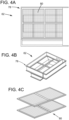
- FIGS. 4A-4C show various views of an example of the FOD screen 62 in which an anti-icing coating can be applied according to an embodiment of the invention.
- the FOD screen 62 comprises a frame structure 78 with a screen 80 enclosed by the frame structure.
- the frame structure 78 is formed from rails, support rods, or the like.
- the rails extend horizontally and vertically across to define individual segments of sub-frame structures each having a mesh screen. With this configuration, the anti-icing coating is applied on the surfaces of the screen 80 that are in the combustion inlet air path.
- the FOD screen 62 can include more than one screen 80 and includes an air sock placed over the screen(s).
- FIG. 4C shows an example of two screens 80 that can be placed over one another and placed in the frame structure 78 depicted in FIGS. 4A and 4B . With this configuration, the anti-icing coating can be applied on the surfaces of both of the screens 80.
- the anti-icing coating can be applied to the screen(s) and sock of the FOD screen 62 by using any of a number of well-known methodologies. In one embodiment, the anti-icing coating can be applied to each of the screen(s) and sock of the FOD screen 62 by using a spray and dip method. The regions of the screen(s) and sock of the FOD screen that are applied with the anti-icing coating include locations where there is direct particle impact and locations without direct particle impact. Applying the anti-icing coating to the screen(s) 80 and sock transforms the FOD screen 62 to an icephobic FOD screen that inhibits the formation of ice that can lead to damage of the gas turbine engine 12 and possible shut down of the turbine.
- the FOD screen 62 is described and depicted with a square or rectangular shape, it is understood that the FOD screen can take the form of other shapes that include, but are not limited to elliptical shapes.
- the shape of the FOD screen can depend on a variety of factors that include the shape of the ducts used in the combustion inlet air path, the location of FOD screen (e.g., against the wall of the silencer, abutting the bell mouth of the inlet of the gas turbine engine, etc.).
- the controller 74 can monitor the effectiveness of the anti-icing coating that is provided to the FOD screen 62. For example, since ice on the FOD screen 62 can lead to a differential pressure across the FOD screen, a differential pressure measurement obtained from FOD screen 62 can be used as an indication of the presence of ice on the screen.
- the system 48 can further include at least one differential pressure sensor operatively coupled to the FOD screen 62 to obtain a differential pressure measurement across the FOD screen.
- FIG. 3 shows a differential pressure sensor P1 and a differential pressure sensor P2 located on opposing sides of the FOD screen 62 in the combustion inlet air path. In this manner, the controller 74 can obtain the differential pressure measurements from the differential pressure sensors P1 and P2.
- controller 74 determines that there is a differential pressure increase across the FOD screen 62 (i.e., a reduction in the air flow going through the turbine engine 12), then the controller can correlate this to ice formation, assuming that the differential pressure increase is occurring in an environment in which icing conditions are present.
- Other components in the combustion inlet air path between the air filter inlet house 52 and the inlet of the gas turbine engine 12 can have an anti-icing coating applied to a surface to prevent the formation of ice.
- These other components can include, but are not limited to, the silencer 60, the inlet plenum/inlet volute 42 that supply the combustion inlet air to the inlet of the gas turbine engine, the inlet guide vanes that direct the combustion inlet air to the inlet of the gas turbine engine 12, and the inlet struts that support the combustion inlet air duct 56. Applying an anti-icing coating to one or more of these components can complement the anti-icing coating applied to the FOD screen 62.
- the configuration of the system 48 that is depicted in FIG. 3 that includes the array of hydrophobic pulse filters 76 along with at least one component (including the FOD screen) in the combustion inlet air path between the air filter inlet house 52 and the inlet of the gas turbine engine 12 that has a surface with an anti-icing coating, allows the various embodiments of the present invention to eliminate the possibility of ice accretion. This allows the gas turbine engine to operate continuously during icing conditions.
- system 48 obviates the need to utilize an anti-icing system to heat the intake air, thereby maximizing efficiency and cost effectiveness of the gas turbine system 50.
- the system 48 can be utilized to supplement the anti-icing features provided by those anti-icing systems by providing enhanced anti-icing in the combustion inlet air path.
- the system 48 can be used in place of those anti-icing systems already implemented in a gas turbine system. To this extent, the system 48 can be utilized to avoid parasitic loads that are associated with using these anti-icing systems.
- the anti-icing that is provided by the system 48 can be enhanced by configuring a heating unit about the combustion inlet air path that can have ice formation when icing conditions are present.
- FIG. 3 shows a schematic representation of an optional heating unit 82 that can be operatively coupled to the air filter inlet house 52.
- the heating unit 82 can be placed after the coil section (not illustrated) and the array of hydrophobic pulse filters 76.
- the controller 74 can direct the heating unit 82 to apply heat to the air intake system 16 in response to determining the presence of icing conditions.
Landscapes
- Engineering & Computer Science (AREA)
- Chemical & Material Sciences (AREA)
- Combustion & Propulsion (AREA)
- Mechanical Engineering (AREA)
- General Engineering & Computer Science (AREA)
- Filtering Of Dispersed Particles In Gases (AREA)
- Structures Of Non-Positive Displacement Pumps (AREA)
- Control Of Turbines (AREA)
Claims (8)
- Gasturbinensystem (10,16,50), umfassend:ein Gasturbinentriebwerk (12);ein Luftansaugsystem (16), um Luft für eine Zuführung an das Gasturbinentriebwerk (12) anzusaugen, das Luftansaugsystem (16) umfassend ein Luftfiltereinlassgehäuse (24,52), um die Ansaugluft zu filtern, wobei das Luftfiltereinlassgehäuse (24,52) mindestens eine Filterstufe einschließt, die eine Anordnung von Impulsfiltern (76) aufweist, wobei jeder der Impulsfilter hydrophob ist,einen Verbrennungseinlassluftweg in Fluidverbindung mit dem Luftansaugsystem (16) und dem Gasturbinentriebwerk (12), wobei der Verbrennungseinlassluftweg die gefilterte Luft aus dem Luftfiltereinlassgehäuse (24,52) empfängt und die gefilterte Luft als Verbrennungseinlassluft einem Einlass des Gasturbinentriebwerks (12) zuführt; undeinen Schirm (40,62) gegen Fremdkörperbeschädigung (FOD) in dem Verbrennungseinlassluftweg zwischen dem Luftfiltereinlassgehäuse (24,52) und dem Einlass des Gasturbinentriebwerks (12), um zu verhindern, dass Debris in den Einlass des Gasturbinentriebwerks (12) gelangt,dadurch gekennzeichnet, dassder FOD-Schirm (40,62) einen oder mehrere Maschenschirme (80) und einen Luftsack einschließt, der oberhalb des einen oder der mehreren Maschenschirme (80) platziert ist, wobei der eine oder die mehreren Maschenschirme (80) in einer Rahmenstruktur (78) umschlossen sind, die sich horizontal und vertikal erstreckende Schienen aufweist, die einzelne Segmente von Unterrahmenstrukturen definieren, die durch Schnittpunkte der sich horizontal erstreckenden Schienen mit den sich vertikal erstreckenden Schienen ausgebildet werden, wobei jedes einzelne Segment der Unterrahmenstrukturen Abschnitte des einen oder der mehreren Maschenschirme (80) umschließt, wobei eine Oberfläche jedes des einen oder der mehreren Maschenschirme (80) in den einzelnen Segmenten der Unterrahmenstrukturen und des Luftsacks, der oberhalb des einen oder der mehreren Schirme platziert ist, eine Vereisungsschutzbeschichtung umfasst, um eine Eisausbildung darauf zu verhindern, wobei die Vereisungsschutzbeschichtung auf jeden des einen oder der mehreren Maschenschirme (80) in den einzelnen Segmenten der Unterrahmenstrukturen und den Luftsack an Stellen, an denen es zu einem direkten Partikelaufprall mit Partikeln kommt, die durch den Verbrennungseinlassluftweg hindurch strömen, und an Stellen ohne direkten Partikelaufprall mit den Partikeln, die durch den Verbrennungseinlassluftweg hindurch strömen, aufgetragen ist.
- Gasturbinensystem (10,16,50) nach Anspruch 1, wobei die Vereisungsschutzbeschichtung ferner auf eine oder mehrere der folgenden Komponenten aufgetragen wird: Wetterhauben (26), die auf dem Luftfiltereinlassgehäuse (24,52) angebracht sind, und in dem Verbrennungseinlassluftweg: einen Schalldämpfer (36,60) der den Lärm verringert, der mit der Ansaugluft verknüpft ist, einer Einlasskammer/einen Einlassdiffusor (42), die die Verbrennungseinlassluft dem Einlass des Gasturbinentriebwerks (12) zuführen, Einlassleitschaufeln, die die Verbrennungseinlassluft zu dem Einlass des Gasturbinentriebwerks (12) leiten, und Einlassstreben, die die Einlasskammer/den Einlassdiffusor (42) stützen, die die Verbrennungseinlassluft dem Einlass des Gasturbinentriebwerks (12) zuführen.
- System nach Anspruch 1, ferner umfassend eine Heizeinheit (82), die mit dem Luftfiltereinlassgehäuse (24,52) wirkgekoppelt ist.
- Gasturbinensystem (10,16,50) nach Anspruch 1, ferner umfassend mindestens einen Differenzdrucksensor (P1,P2), der mit dem FOD-Schirm (40,62) wirkgekoppelt ist, wobei der mindestens eine Differenzdrucksensor (P1,P2) eine Differenzdruckmessung über den FOD-Schirm (40,62) erhält und die Differenzdruckmessung einen Hinweis auf Eisausbildung auf dem FOD-Schirm (40,62) bereitstellt.
- System nach Anspruch 6, ferner umfassend eine Steuervorrichtung (74), um die Differenzdruckmessung zu überwachen, um eine Eisausbildung auf mindestens einer Komponente zu bestimmen.
- System nach Anspruch 1, wobei das Gasturbinentriebwerk (12) eine aeroderivative Gasturbine (22) umfasst.
- Verfahren zum Verhindern einer Vereisung in dem Verbrennungseinlassluftweg eines Gasturbinensystems (10,16,50), das ein Gasturbinentriebwerk (12), ein Luftansaugsystem (16), um Luft für die Zuführung des Gasturbinentriebwerks (12) anzusaugen, und einen Verbrennungseinlassluftweg aufweist, um Verbrennungseinlassluft einem Einlass des Gasturbinentriebwerks (12) zuzuführen, das Verfahren umfassend:Filtern der Ansaugluft in dem Luftansaugsystem (16) mit einem Luftfiltereinlassgehäuse (24,52), das mindestens eine Filterstufe einschließt, die eine Anordnung von hydrophoben Impulsfiltern (76) aufweist;Zuführen der gefilterten Luft als Verbrennungseinlassluft zu dem Einlass des Gasturbinentriebwerks (12); undAuftragen einer Vereisungsschutzbeschichtung auf eine Oberfläche von mindestens einer Komponente in einem Weg der Verbrennungseinlassluft zwischen dem Luftfiltereinlassgehäuse (24,52) und dem Einlass des Gasturbinentriebwerks (12), um das Eis daran zu hindern, sich auf der mindestens einen Komponente auszubilden, wobei die mindestens eine Komponente einen Schirm (FOD) gegen Fremdkörperbeschädigung (40,62) umfasst, wobei der FOD-Schirm (40,62) ein oder mehrere Maschenschirme (80) und einen Luftsack einschließt, der oberhalb des einen oder der mehreren Maschenschirme (80) platziert ist, wobei der eine oder die mehreren Maschenschirme (80) in einer Rahmenstruktur (78) umschlossen sind, die sich horizontal und vertikal erstreckende Schienen aufweist, die einzelne Segmente von Unterrahmenstrukturen definieren, die durch Schnittpunkte der sich horizontal erstreckenden Schienen mit den sich vertikal erstreckenden Schienen ausgebildet werden, wobei jedes einzelne Segment von Unterrahmenstrukturen Abschnitte des einen oder der mehreren Maschenschirme (80) umschließt, wobei eine Oberfläche jedes des einen oder der mehreren Maschenschirme (80) in den einzelnen Segmenten von Unterrahmenstrukturen und des Luftsacks, der oberhalb des einen oder der mehreren Schirme die Vereisungsschutzbeschichtung umfasst, um Eisausbildung darauf zu verhindern, wobei die Vereisungsschutzbeschichtung auf jeden des einen oder der mehreren Maschenschirme (80) in den einzelnen Segmenten der Unterrahmenstrukturen und den Luftsack an Stellen, an denen es zu einem direkten Partikelaufprall mit Partikeln kommt, die durch den Verbrennungseinlassluftweg hindurch strömen, und an Stellen ohne direkten Partikelaufprall mit den Partikeln aufgetragen ist, die durch den Verbrennungseinlassluftweg hindurch strömen.
- Verfahren nach Anspruch 7, ferner umfassend das Auftragen der Vereisungsschutzbeschichtung auf eine oder mehrere der folgenden Komponenten: Wetterhauben (26), die auf dem Luftfiltereinlassgehäuse (24,52) angebracht sind, und in dem Verbrennungseinlassluftweg: einen Schalldämpfer (36,60), der den Lärm verringert, der mit der Ansaugluft verknüpft ist, einer Einlasskammer/einen Einlassdiffusor (42), die die Verbrennungseinlassluft dem Einlass des Gasturbinentriebwerks (12) zuführen, Einlassleitschaufeln, die die Verbrennungseinlassluft zu dem Einlass des Gasturbinentriebwerks (12) leiten, und Einlassstreben, die die Einlasskammer/den Einlassdiffusor (42) stützen, die die Verbrennungseinlassluft dem Einlass des Gasturbinentriebwerks (12) zuführen.
Applications Claiming Priority (1)
| Application Number | Priority Date | Filing Date | Title |
|---|---|---|---|
| US17/560,367 US11846231B2 (en) | 2021-12-23 | 2021-12-23 | System and method for preventing icing in the combustion inlet air path of a gas turbine system |
Publications (2)
| Publication Number | Publication Date |
|---|---|
| EP4202196A1 EP4202196A1 (de) | 2023-06-28 |
| EP4202196B1 true EP4202196B1 (de) | 2025-01-29 |
Family
ID=84421023
Family Applications (1)
| Application Number | Title | Priority Date | Filing Date |
|---|---|---|---|
| EP22211615.4A Active EP4202196B1 (de) | 2021-12-23 | 2022-12-06 | System und verfahren zur verhinderung von vereisung im verbrennungseinlassluftweg einer gasturbinenanlage |
Country Status (5)
| Country | Link |
|---|---|
| US (1) | US11846231B2 (de) |
| EP (1) | EP4202196B1 (de) |
| JP (1) | JP2023094558A (de) |
| KR (1) | KR20230096861A (de) |
| CN (1) | CN116335824A (de) |
Families Citing this family (2)
| Publication number | Priority date | Publication date | Assignee | Title |
|---|---|---|---|---|
| US12228075B2 (en) * | 2022-12-09 | 2025-02-18 | General Electric Company | Integral engine inlet frame air-cooled oil cooling apparatus |
| JP2025099125A (ja) * | 2023-12-21 | 2025-07-03 | 三菱重工業株式会社 | 凍結防止制御装置、吸気ダクト設備、ガスタービン設備、及び凍結防止方法 |
Family Cites Families (18)
| Publication number | Priority date | Publication date | Assignee | Title |
|---|---|---|---|---|
| US20060281861A1 (en) * | 2005-06-13 | 2006-12-14 | Putnam John W | Erosion resistant anti-icing coatings |
| US7632339B2 (en) * | 2006-12-18 | 2009-12-15 | General Electric Company | Moisture removal apparatus and method |
| US20090241509A1 (en) | 2008-03-25 | 2009-10-01 | Isaac Jon Hogate | Turbine engine inlet strut deicing |
| WO2012118805A2 (en) | 2011-02-28 | 2012-09-07 | Research Foundation Of The City University Of New York | Polymers having superhydrophobic surfaces |
| US9040145B2 (en) | 2011-02-28 | 2015-05-26 | Research Foundation Of The City University Of New York | Polymer having superhydrophobic surface |
| US9067679B2 (en) | 2011-12-30 | 2015-06-30 | Aerospace Filtration Systems, Inc. | Heated screen for air intake of aircraft engines |
| US9827735B2 (en) * | 2012-03-09 | 2017-11-28 | United Technologies Corporation | Erosion resistant and hydrophobic article |
| US9719423B2 (en) * | 2012-09-04 | 2017-08-01 | General Electric Company | Inlet air chilling system with humidity control and energy recovery |
| US9546280B2 (en) | 2012-12-07 | 2017-01-17 | Hrl Laboratories, Llc | Structural coatings with dewetting and anti-icing properties, and coating precursors for fabricating same |
| WO2015019096A1 (en) * | 2013-08-07 | 2015-02-12 | Isentropic Ltd | Hybrid power generation system |
| US10220353B2 (en) | 2014-08-28 | 2019-03-05 | Bha Altair, Llc | Filter water management using hydrophilic material |
| US9200568B1 (en) * | 2014-09-24 | 2015-12-01 | General Electric Company | Inlet air filtration system with self-cleaning filter bag |
| US9567907B2 (en) * | 2015-02-24 | 2017-02-14 | General Electrical Company | Imaging assisted gas turbine anti-icing system |
| RU2017140844A (ru) | 2015-04-27 | 2019-05-27 | Те Риджентс Оф Те Юниверсити Оф Мичиган | Долговечные антиобледенительные поверхности |
| US20180015403A1 (en) * | 2016-07-15 | 2018-01-18 | General Electric Company | De-icing of pulse filters |
| CN210031689U (zh) | 2019-05-20 | 2020-02-07 | 松花江水力发电有限公司丰满大坝重建工程建设局 | 大坝坝体防冻融保温防冰拔保护体系 |
| CN110863225A (zh) | 2019-11-28 | 2020-03-06 | 湖北理工学院 | 一种铝基材表面的疏冰改性方法 |
| CN111482341B (zh) | 2020-05-13 | 2021-09-03 | 清华大学 | 一种疏冰涂层及其制备方法和应用 |
-
2021
- 2021-12-23 US US17/560,367 patent/US11846231B2/en active Active
-
2022
- 2022-11-18 CN CN202211445443.2A patent/CN116335824A/zh active Pending
- 2022-11-22 JP JP2022186614A patent/JP2023094558A/ja active Pending
- 2022-12-06 EP EP22211615.4A patent/EP4202196B1/de active Active
- 2022-12-13 KR KR1020220174241A patent/KR20230096861A/ko active Pending
Also Published As
| Publication number | Publication date |
|---|---|
| US20230203990A1 (en) | 2023-06-29 |
| US11846231B2 (en) | 2023-12-19 |
| JP2023094558A (ja) | 2023-07-05 |
| EP4202196A1 (de) | 2023-06-28 |
| CN116335824A (zh) | 2023-06-27 |
| KR20230096861A (ko) | 2023-06-30 |
Similar Documents
| Publication | Publication Date | Title |
|---|---|---|
| CA2990761C (en) | System for reducing inlet air temperature of a device | |
| JP6408812B2 (ja) | ガスタービン用の防氷システム | |
| EP4202196B1 (de) | System und verfahren zur verhinderung von vereisung im verbrennungseinlassluftweg einer gasturbinenanlage | |
| EP2996792B1 (de) | Filterkammern für gasturbinen und verfahren zur wartung davon | |
| US8163072B2 (en) | Filter washing system for gas turbine engines | |
| CN104564346A (zh) | 旁通燃气轮机入口内聚结器的系统和方法 | |
| US9157367B2 (en) | Turbine inlet air filter system with elbow access gate | |
| CN103703228A (zh) | 用于运行固定式燃气轮机的方法和用于燃气轮机的吸入空气的吸入通道 | |
| KR20230048612A (ko) | 작동 장소에 맞추어진 침입 보호 코팅을 이용하여 가스 터빈 시스템의 공기 흡입 시스템으로의 미립자 침입을 완화시키기 위한 시스템 및 방법 | |
| Meher-Homji et al. | Inlet fogging of gas turbine engines: Part B—practical considerations, control, and O&M aspects | |
| US20180135514A1 (en) | Sound attenuating system for gas turbine engine | |
| EP4134532B1 (de) | System und verfahren zum steuern von niederdruck-rücklaufluft in gasturbinenmotoren | |
| EP2271829B1 (de) | Verfahren zur reinigung eines bauteils eines turboladers unter betriebsbedingungen und turbolader | |
| US20140360217A1 (en) | Cooling system for use in a turbine assembly and method of assembly | |
| US11815018B2 (en) | Box-shaped air intake silencer with vertical baffles for gas turbine system | |
| Mendeleev et al. | Performance Characteristics of A Gas Turbine Unit with Clogged Filters of an Air Filtering and Conditioning System | |
| Oswald et al. | More Efficient Applications for Naval Gas Turbines: Addressing the Mismatch Between Available Technology and the Requirements of Modern Naval Gas Turbine Inlets | |
| Lyons et al. | Utility perspective of selecting air filter for simple-cycle, heavy-duty combustion turbines | |
| Lyons et al. | Utility Perspective of Selecting Air Filter for Simple-Cycle, Heavy-Duty Combustion Turbines | |
| Effiom | Inlet Filtration for Industrial Gas Turbines |
Legal Events
| Date | Code | Title | Description |
|---|---|---|---|
| PUAI | Public reference made under article 153(3) epc to a published international application that has entered the european phase |
Free format text: ORIGINAL CODE: 0009012 |
|
| STAA | Information on the status of an ep patent application or granted ep patent |
Free format text: STATUS: THE APPLICATION HAS BEEN PUBLISHED |
|
| AK | Designated contracting states |
Kind code of ref document: A1 Designated state(s): AL AT BE BG CH CY CZ DE DK EE ES FI FR GB GR HR HU IE IS IT LI LT LU LV MC ME MK MT NL NO PL PT RO RS SE SI SK SM TR |
|
| RAP1 | Party data changed (applicant data changed or rights of an application transferred) |
Owner name: GENERAL ELECTRIC TECHNOLOGY GMBH |
|
| STAA | Information on the status of an ep patent application or granted ep patent |
Free format text: STATUS: REQUEST FOR EXAMINATION WAS MADE |
|
| 17P | Request for examination filed |
Effective date: 20231215 |
|
| RBV | Designated contracting states (corrected) |
Designated state(s): AL AT BE BG CH CY CZ DE DK EE ES FI FR GB GR HR HU IE IS IT LI LT LU LV MC ME MK MT NL NO PL PT RO RS SE SI SK SM TR |
|
| GRAP | Despatch of communication of intention to grant a patent |
Free format text: ORIGINAL CODE: EPIDOSNIGR1 |
|
| RIC1 | Information provided on ipc code assigned before grant |
Ipc: F02C 7/055 20060101ALI20240924BHEP Ipc: F02C 7/052 20060101ALI20240924BHEP Ipc: F02C 7/047 20060101ALI20240924BHEP Ipc: F02C 7/045 20060101AFI20240924BHEP |
|
| STAA | Information on the status of an ep patent application or granted ep patent |
Free format text: STATUS: GRANT OF PATENT IS INTENDED |
|
| GRAS | Grant fee paid |
Free format text: ORIGINAL CODE: EPIDOSNIGR3 |
|
| INTG | Intention to grant announced |
Effective date: 20241030 |
|
| GRAA | (expected) grant |
Free format text: ORIGINAL CODE: 0009210 |
|
| STAA | Information on the status of an ep patent application or granted ep patent |
Free format text: STATUS: THE PATENT HAS BEEN GRANTED |
|
| AK | Designated contracting states |
Kind code of ref document: B1 Designated state(s): AL AT BE BG CH CY CZ DE DK EE ES FI FR GB GR HR HU IE IS IT LI LT LU LV MC ME MK MT NL NO PL PT RO RS SE SI SK SM TR |
|
| REG | Reference to a national code |
Ref country code: GB Ref legal event code: FG4D |
|
| REG | Reference to a national code |
Ref country code: CH Ref legal event code: EP |
|
| REG | Reference to a national code |
Ref country code: DE Ref legal event code: R096 Ref document number: 602022010089 Country of ref document: DE |
|
| REG | Reference to a national code |
Ref country code: IE Ref legal event code: FG4D |
|
| REG | Reference to a national code |
Ref country code: NL Ref legal event code: FP |
|
| PG25 | Lapsed in a contracting state [announced via postgrant information from national office to epo] |
Ref country code: RS Free format text: LAPSE BECAUSE OF FAILURE TO SUBMIT A TRANSLATION OF THE DESCRIPTION OR TO PAY THE FEE WITHIN THE PRESCRIBED TIME-LIMIT Effective date: 20250429 |
|
| PG25 | Lapsed in a contracting state [announced via postgrant information from national office to epo] |
Ref country code: FI Free format text: LAPSE BECAUSE OF FAILURE TO SUBMIT A TRANSLATION OF THE DESCRIPTION OR TO PAY THE FEE WITHIN THE PRESCRIBED TIME-LIMIT Effective date: 20250129 |
|
| PG25 | Lapsed in a contracting state [announced via postgrant information from national office to epo] |
Ref country code: PL Free format text: LAPSE BECAUSE OF FAILURE TO SUBMIT A TRANSLATION OF THE DESCRIPTION OR TO PAY THE FEE WITHIN THE PRESCRIBED TIME-LIMIT Effective date: 20250129 |
|
| PG25 | Lapsed in a contracting state [announced via postgrant information from national office to epo] |
Ref country code: ES Free format text: LAPSE BECAUSE OF FAILURE TO SUBMIT A TRANSLATION OF THE DESCRIPTION OR TO PAY THE FEE WITHIN THE PRESCRIBED TIME-LIMIT Effective date: 20250129 |
|
| REG | Reference to a national code |
Ref country code: LT Ref legal event code: MG9D |
|
| PG25 | Lapsed in a contracting state [announced via postgrant information from national office to epo] |
Ref country code: NO Free format text: LAPSE BECAUSE OF FAILURE TO SUBMIT A TRANSLATION OF THE DESCRIPTION OR TO PAY THE FEE WITHIN THE PRESCRIBED TIME-LIMIT Effective date: 20250429 Ref country code: IS Free format text: LAPSE BECAUSE OF FAILURE TO SUBMIT A TRANSLATION OF THE DESCRIPTION OR TO PAY THE FEE WITHIN THE PRESCRIBED TIME-LIMIT Effective date: 20250529 |
|
| REG | Reference to a national code |
Ref country code: AT Ref legal event code: MK05 Ref document number: 1763637 Country of ref document: AT Kind code of ref document: T Effective date: 20250129 |
|
| PG25 | Lapsed in a contracting state [announced via postgrant information from national office to epo] |
Ref country code: HR Free format text: LAPSE BECAUSE OF FAILURE TO SUBMIT A TRANSLATION OF THE DESCRIPTION OR TO PAY THE FEE WITHIN THE PRESCRIBED TIME-LIMIT Effective date: 20250129 |
|
| PG25 | Lapsed in a contracting state [announced via postgrant information from national office to epo] |
Ref country code: LV Free format text: LAPSE BECAUSE OF FAILURE TO SUBMIT A TRANSLATION OF THE DESCRIPTION OR TO PAY THE FEE WITHIN THE PRESCRIBED TIME-LIMIT Effective date: 20250129 Ref country code: PT Free format text: LAPSE BECAUSE OF FAILURE TO SUBMIT A TRANSLATION OF THE DESCRIPTION OR TO PAY THE FEE WITHIN THE PRESCRIBED TIME-LIMIT Effective date: 20250529 |
|
| PG25 | Lapsed in a contracting state [announced via postgrant information from national office to epo] |
Ref country code: GR Free format text: LAPSE BECAUSE OF FAILURE TO SUBMIT A TRANSLATION OF THE DESCRIPTION OR TO PAY THE FEE WITHIN THE PRESCRIBED TIME-LIMIT Effective date: 20250430 Ref country code: BG Free format text: LAPSE BECAUSE OF FAILURE TO SUBMIT A TRANSLATION OF THE DESCRIPTION OR TO PAY THE FEE WITHIN THE PRESCRIBED TIME-LIMIT Effective date: 20250129 |
|
| PG25 | Lapsed in a contracting state [announced via postgrant information from national office to epo] |
Ref country code: AT Free format text: LAPSE BECAUSE OF FAILURE TO SUBMIT A TRANSLATION OF THE DESCRIPTION OR TO PAY THE FEE WITHIN THE PRESCRIBED TIME-LIMIT Effective date: 20250129 |
|
| PG25 | Lapsed in a contracting state [announced via postgrant information from national office to epo] |
Ref country code: SE Free format text: LAPSE BECAUSE OF FAILURE TO SUBMIT A TRANSLATION OF THE DESCRIPTION OR TO PAY THE FEE WITHIN THE PRESCRIBED TIME-LIMIT Effective date: 20250129 |
|
| RAP4 | Party data changed (patent owner data changed or rights of a patent transferred) |
Owner name: GE VERNOVA TECHNOLOGY GMBH |
|
| PG25 | Lapsed in a contracting state [announced via postgrant information from national office to epo] |
Ref country code: SM Free format text: LAPSE BECAUSE OF FAILURE TO SUBMIT A TRANSLATION OF THE DESCRIPTION OR TO PAY THE FEE WITHIN THE PRESCRIBED TIME-LIMIT Effective date: 20250129 |
|
| PG25 | Lapsed in a contracting state [announced via postgrant information from national office to epo] |
Ref country code: DK Free format text: LAPSE BECAUSE OF FAILURE TO SUBMIT A TRANSLATION OF THE DESCRIPTION OR TO PAY THE FEE WITHIN THE PRESCRIBED TIME-LIMIT Effective date: 20250129 |
|
| PG25 | Lapsed in a contracting state [announced via postgrant information from national office to epo] |
Ref country code: CZ Free format text: LAPSE BECAUSE OF FAILURE TO SUBMIT A TRANSLATION OF THE DESCRIPTION OR TO PAY THE FEE WITHIN THE PRESCRIBED TIME-LIMIT Effective date: 20250129 Ref country code: EE Free format text: LAPSE BECAUSE OF FAILURE TO SUBMIT A TRANSLATION OF THE DESCRIPTION OR TO PAY THE FEE WITHIN THE PRESCRIBED TIME-LIMIT Effective date: 20250129 |
|
| PG25 | Lapsed in a contracting state [announced via postgrant information from national office to epo] |
Ref country code: RO Free format text: LAPSE BECAUSE OF FAILURE TO SUBMIT A TRANSLATION OF THE DESCRIPTION OR TO PAY THE FEE WITHIN THE PRESCRIBED TIME-LIMIT Effective date: 20250129 |
|
| PG25 | Lapsed in a contracting state [announced via postgrant information from national office to epo] |
Ref country code: SK Free format text: LAPSE BECAUSE OF FAILURE TO SUBMIT A TRANSLATION OF THE DESCRIPTION OR TO PAY THE FEE WITHIN THE PRESCRIBED TIME-LIMIT Effective date: 20250129 |
|
| REG | Reference to a national code |
Ref country code: DE Ref legal event code: R097 Ref document number: 602022010089 Country of ref document: DE |
|
| PLBE | No opposition filed within time limit |
Free format text: ORIGINAL CODE: 0009261 |
|
| STAA | Information on the status of an ep patent application or granted ep patent |
Free format text: STATUS: NO OPPOSITION FILED WITHIN TIME LIMIT |
|
| PGFP | Annual fee paid to national office [announced via postgrant information from national office to epo] |
Ref country code: NL Payment date: 20251119 Year of fee payment: 4 |