EP4134532B1 - System und verfahren zum steuern von niederdruck-rücklaufluft in gasturbinenmotoren - Google Patents
System und verfahren zum steuern von niederdruck-rücklaufluft in gasturbinenmotoren Download PDFInfo
- Publication number
- EP4134532B1 EP4134532B1 EP22187148.6A EP22187148A EP4134532B1 EP 4134532 B1 EP4134532 B1 EP 4134532B1 EP 22187148 A EP22187148 A EP 22187148A EP 4134532 B1 EP4134532 B1 EP 4134532B1
- Authority
- EP
- European Patent Office
- Prior art keywords
- air
- gas turbine
- low pressure
- intake system
- air intake
- Prior art date
- Legal status (The legal status is an assumption and is not a legal conclusion. Google has not performed a legal analysis and makes no representation as to the accuracy of the status listed.)
- Active
Links
Images
Classifications
-
- F—MECHANICAL ENGINEERING; LIGHTING; HEATING; WEAPONS; BLASTING
- F02—COMBUSTION ENGINES; HOT-GAS OR COMBUSTION-PRODUCT ENGINE PLANTS
- F02C—GAS-TURBINE PLANTS; AIR INTAKES FOR JET-PROPULSION PLANTS; CONTROLLING FUEL SUPPLY IN AIR-BREATHING JET-PROPULSION PLANTS
- F02C7/00—Features, components parts, details or accessories, not provided for in, or of interest apart form groups F02C1/00 - F02C6/00; Air intakes for jet-propulsion plants
- F02C7/24—Heat or noise insulation
-
- F—MECHANICAL ENGINEERING; LIGHTING; HEATING; WEAPONS; BLASTING
- F01—MACHINES OR ENGINES IN GENERAL; ENGINE PLANTS IN GENERAL; STEAM ENGINES
- F01D—NON-POSITIVE DISPLACEMENT MACHINES OR ENGINES, e.g. STEAM TURBINES
- F01D17/00—Regulating or controlling by varying flow
- F01D17/10—Final actuators
- F01D17/12—Final actuators arranged in stator parts
- F01D17/14—Final actuators arranged in stator parts varying effective cross-sectional area of nozzles or guide conduits
- F01D17/141—Final actuators arranged in stator parts varying effective cross-sectional area of nozzles or guide conduits by means of shiftable members or valves obturating part of the flow path
- F01D17/145—Final actuators arranged in stator parts varying effective cross-sectional area of nozzles or guide conduits by means of shiftable members or valves obturating part of the flow path by means of valves, e.g. for steam turbines
-
- F—MECHANICAL ENGINEERING; LIGHTING; HEATING; WEAPONS; BLASTING
- F01—MACHINES OR ENGINES IN GENERAL; ENGINE PLANTS IN GENERAL; STEAM ENGINES
- F01D—NON-POSITIVE DISPLACEMENT MACHINES OR ENGINES, e.g. STEAM TURBINES
- F01D21/00—Shutting-down of machines or engines, e.g. in emergency; Regulating, controlling, or safety means not otherwise provided for
- F01D21/003—Arrangements for testing or measuring
-
- F—MECHANICAL ENGINEERING; LIGHTING; HEATING; WEAPONS; BLASTING
- F01—MACHINES OR ENGINES IN GENERAL; ENGINE PLANTS IN GENERAL; STEAM ENGINES
- F01D—NON-POSITIVE DISPLACEMENT MACHINES OR ENGINES, e.g. STEAM TURBINES
- F01D25/00—Component parts, details, or accessories, not provided for in, or of interest apart from, other groups
- F01D25/30—Exhaust heads, chambers, or the like
- F01D25/305—Exhaust heads, chambers, or the like with fluid, e.g. liquid injection
-
- F—MECHANICAL ENGINEERING; LIGHTING; HEATING; WEAPONS; BLASTING
- F02—COMBUSTION ENGINES; HOT-GAS OR COMBUSTION-PRODUCT ENGINE PLANTS
- F02C—GAS-TURBINE PLANTS; AIR INTAKES FOR JET-PROPULSION PLANTS; CONTROLLING FUEL SUPPLY IN AIR-BREATHING JET-PROPULSION PLANTS
- F02C6/00—Plural gas-turbine plants; Combinations of gas-turbine plants with other apparatus; Adaptations of gas-turbine plants for special use
- F02C6/04—Gas-turbine plants providing heated or pressurised working fluid for other apparatus, e.g. without mechanical power output
- F02C6/06—Gas-turbine plants providing heated or pressurised working fluid for other apparatus, e.g. without mechanical power output providing compressed gas
-
- F—MECHANICAL ENGINEERING; LIGHTING; HEATING; WEAPONS; BLASTING
- F02—COMBUSTION ENGINES; HOT-GAS OR COMBUSTION-PRODUCT ENGINE PLANTS
- F02C—GAS-TURBINE PLANTS; AIR INTAKES FOR JET-PROPULSION PLANTS; CONTROLLING FUEL SUPPLY IN AIR-BREATHING JET-PROPULSION PLANTS
- F02C6/00—Plural gas-turbine plants; Combinations of gas-turbine plants with other apparatus; Adaptations of gas-turbine plants for special use
- F02C6/18—Plural gas-turbine plants; Combinations of gas-turbine plants with other apparatus; Adaptations of gas-turbine plants for special use using the waste heat of gas-turbine plants outside the plants themselves, e.g. gas-turbine power heat plants
-
- F—MECHANICAL ENGINEERING; LIGHTING; HEATING; WEAPONS; BLASTING
- F02—COMBUSTION ENGINES; HOT-GAS OR COMBUSTION-PRODUCT ENGINE PLANTS
- F02C—GAS-TURBINE PLANTS; AIR INTAKES FOR JET-PROPULSION PLANTS; CONTROLLING FUEL SUPPLY IN AIR-BREATHING JET-PROPULSION PLANTS
- F02C7/00—Features, components parts, details or accessories, not provided for in, or of interest apart form groups F02C1/00 - F02C6/00; Air intakes for jet-propulsion plants
- F02C7/04—Air intakes for gas-turbine plants or jet-propulsion plants
- F02C7/047—Heating to prevent icing
-
- F—MECHANICAL ENGINEERING; LIGHTING; HEATING; WEAPONS; BLASTING
- F02—COMBUSTION ENGINES; HOT-GAS OR COMBUSTION-PRODUCT ENGINE PLANTS
- F02C—GAS-TURBINE PLANTS; AIR INTAKES FOR JET-PROPULSION PLANTS; CONTROLLING FUEL SUPPLY IN AIR-BREATHING JET-PROPULSION PLANTS
- F02C7/00—Features, components parts, details or accessories, not provided for in, or of interest apart form groups F02C1/00 - F02C6/00; Air intakes for jet-propulsion plants
- F02C7/04—Air intakes for gas-turbine plants or jet-propulsion plants
- F02C7/05—Air intakes for gas-turbine plants or jet-propulsion plants having provisions for obviating the penetration of damaging objects or particles
- F02C7/052—Air intakes for gas-turbine plants or jet-propulsion plants having provisions for obviating the penetration of damaging objects or particles with dust-separation devices
-
- F—MECHANICAL ENGINEERING; LIGHTING; HEATING; WEAPONS; BLASTING
- F02—COMBUSTION ENGINES; HOT-GAS OR COMBUSTION-PRODUCT ENGINE PLANTS
- F02C—GAS-TURBINE PLANTS; AIR INTAKES FOR JET-PROPULSION PLANTS; CONTROLLING FUEL SUPPLY IN AIR-BREATHING JET-PROPULSION PLANTS
- F02C7/00—Features, components parts, details or accessories, not provided for in, or of interest apart form groups F02C1/00 - F02C6/00; Air intakes for jet-propulsion plants
- F02C7/12—Cooling of plants
- F02C7/14—Cooling of plants of fluids in the plant, e.g. lubricant or fuel
- F02C7/141—Cooling of plants of fluids in the plant, e.g. lubricant or fuel of working fluid
-
- F—MECHANICAL ENGINEERING; LIGHTING; HEATING; WEAPONS; BLASTING
- F02—COMBUSTION ENGINES; HOT-GAS OR COMBUSTION-PRODUCT ENGINE PLANTS
- F02C—GAS-TURBINE PLANTS; AIR INTAKES FOR JET-PROPULSION PLANTS; CONTROLLING FUEL SUPPLY IN AIR-BREATHING JET-PROPULSION PLANTS
- F02C9/00—Controlling gas-turbine plants; Controlling fuel supply in air- breathing jet-propulsion plants
- F02C9/16—Control of working fluid flow
- F02C9/18—Control of working fluid flow by bleeding, bypassing or acting on variable working fluid interconnections between turbines or compressors or their stages
-
- F—MECHANICAL ENGINEERING; LIGHTING; HEATING; WEAPONS; BLASTING
- F05—INDEXING SCHEMES RELATING TO ENGINES OR PUMPS IN VARIOUS SUBCLASSES OF CLASSES F01-F04
- F05D—INDEXING SCHEME FOR ASPECTS RELATING TO NON-POSITIVE-DISPLACEMENT MACHINES OR ENGINES, GAS-TURBINES OR JET-PROPULSION PLANTS
- F05D2220/00—Application
- F05D2220/30—Application in turbines
- F05D2220/32—Application in turbines in gas turbines
-
- F—MECHANICAL ENGINEERING; LIGHTING; HEATING; WEAPONS; BLASTING
- F05—INDEXING SCHEMES RELATING TO ENGINES OR PUMPS IN VARIOUS SUBCLASSES OF CLASSES F01-F04
- F05D—INDEXING SCHEME FOR ASPECTS RELATING TO NON-POSITIVE-DISPLACEMENT MACHINES OR ENGINES, GAS-TURBINES OR JET-PROPULSION PLANTS
- F05D2260/00—Function
- F05D2260/20—Heat transfer, e.g. cooling
-
- F—MECHANICAL ENGINEERING; LIGHTING; HEATING; WEAPONS; BLASTING
- F05—INDEXING SCHEMES RELATING TO ENGINES OR PUMPS IN VARIOUS SUBCLASSES OF CLASSES F01-F04
- F05D—INDEXING SCHEME FOR ASPECTS RELATING TO NON-POSITIVE-DISPLACEMENT MACHINES OR ENGINES, GAS-TURBINES OR JET-PROPULSION PLANTS
- F05D2270/00—Control
- F05D2270/30—Control parameters, e.g. input parameters
- F05D2270/303—Temperature
Definitions
- Embodiments of this disclosure relate generally to gas turbine systems, and more specifically, to a system and method for controlling low pressure recoup air in a gas turbine engine.
- Gas turbine engines are utilized globally for electric power generation or as mechanical drives for operating equipment under a variety of climatic conditions. Operation during cold ambient temperature and high humidity conditions can lead to icing problems in gas turbine systems in which gas turbine engines are utilized. For example, ice can plug the filtration system of an air intake system to a gas turbine engine causing a significant drop in pressure in the air intake system, which in turn, leads to performance loss (e.g., gas turbine power output deterioration). In extreme cases, there is even a possibility that ice pieces can get ingested into a first blade stage of a compressor in the gas turbine engine, which can cause damage. Ice may also cause the disruption of compressor work because of excessive vibration, or surging by decreasing the inlet flow. Consequently, gas turbine systems that are located in areas where icing conditions can exist are typically equipped with an anti-icing system that can heat the intake air before it enters the compressor of the gas turbine engine.
- US-2017/342902-A1 discloses a system including a compressor having a compressor inlet, a turbine having a plurality of stages disposed within a turbine casing, and a turbine extraction gas (TEG) heating system.
- the turbine is configured to drive the compressor via expansion of combustion products through the plurality of stages.
- the TEG heating system includes a turbine gas extraction system coupled to the turbine casing and to the compressor inlet.
- the turbine gas extraction system is configured to receive a portion of the combustion products as a turbine extraction gas (TEG) from the turbine.
- TEG is received through the turbine casing, the TEG heating system is configured to supply a heated flow to the compressor inlet, and the heated flow includes the TEG.
- the various embodiments of the present invention are directed to providing a novel and nonobvious anti-icing approach for use with a gas turbine system utilizing a gas turbine engine.
- the solution provided by the various embodiments includes using low pressure recoup air vented from the gas turbine engine to aid in heating the air at the inlet of the air intake system to the gas turbine engine during icing conditions, or to aid in heating a gas turbine enclosure that encloses the gas turbine engine during colder ambient conditions.
- low pressure recoup air piping is operatively coupled to the gas turbine engine to carry the low pressure recoup air from the gas turbine engine to a gas turbine combustion exhaust that outputs an exhaust flow from the gas turbine engine to outside of the gas turbine enclosure.
- a first valve and a second valve are operatively coupled to the low pressure recoup air piping.
- the first valve can control a flow of the low pressure recoup air to the gas turbine combustion exhaust, while the second valve can divert the flow of the low pressure recoup air from the low pressure recoup air piping to the gas turbine enclosure.
- a controller is operatively coupled to the first valve and the second valve, and configured to automatically control the flow of the low pressure recoup air from the low pressure recoup air piping to the gas turbine combustion exhaust and/or the gas turbine enclosure and the air intake system.
- the controller comprises control logic that enables the controller to use the low pressure recoup air that is diverted from the low pressure recoup air piping to the gas turbine enclosure to aid in heating the air at the inlet of the air intake system along with air provided at the inlet by a gas turbine enclosure ventilation exhaust system that is operatively coupled to the air intake system, the gas turbine engine, and the gas turbine enclosure, to purge and ventilate heat and exhaust products from the gas turbine engine.
- control logic of the controller can be used for purposes of preventing icing in the air intake system.
- control logic of the controller can use the low pressure recoup air that is diverted from the low pressure recoup air piping to heat the gas turbine enclosure in colder ambient conditions.
- the controller can obtain a first temperature measurement representative of ambient temperature about the air intake system, and a second temperature measurement obtained within the air intake system.
- the logic of the controller enables the controller to control the flow of the low pressure recoup air in the low pressure recoup air piping to the gas turbine combustion exhaust and/or gas turbine enclosure and the air intake system as a function of the ambient temperature measurement, the air intake system temperature measurement, and a predetermined temperature requirement having an ambient temperature constraint and an air intake system temperature differential constraint.
- the controller can control the flow of the low pressure recoup air from the low pressure recoup air piping to the gas turbine combustion exhaust and/or the gas turbine enclosure and the air intake system based on values of the ambient temperature measurement and the air intake system temperature measurement in relation to the ambient temperature constraint and the air intake system temperature differential constraint.
- the ambient temperature constraint comprises an ambient temperature that is less than about 40 degrees F (4.4°C)
- the air intake system temperature differential constraint comprises a temperature difference between 40 degrees F (4.4°C) and the air intake system temperature measurement, or a 10 degree F (5.6°C) increase or rise from the air intake system temperature measurement, whichever is lower.
- the controller can direct the first valve to be 100% open and the second valve to be 0% open (i.e., closed).
- the low pressure recoup air piping will direct all of the flow of the low pressure recoup air to the gas turbine combustion exhaust.
- the controller will direct the gas turbine enclosure ventilation exhaust system to position a ventilation air control damper to move 100% of the ventilation exhaust air from the gas turbine enclosure to ambient.
- the controller will direct the gas turbine enclosure ventilation exhaust system to modulate or gradually position the ventilation air control damper to move a 100% of the ventilation exhaust air from the gas turbine enclosure to the air intake system via air inlet heating ducts in fluid communication with an air filter house of the air intake system.
- the controller can then monitor the effect that moving 100% of the gas turbine enclosure ventilation exhaust air to the air intake system by obtaining additional ambient temperature measurements about the air intake system and temperature measurements within the air intake system.
- the control logic of the controller will compare these temperature measurements to the temperature constraint and the air intake system temperature differential constraint of the predetermined temperature requirement.
- the controller can modulate or gradually open the second valve associated with the low pressure recoup air piping to be 100% open in order to divert a portion of the flow of the low pressure recoup air to the gas turbine enclosure.
- the gas turbine enclosure ventilation exhaust system can use the ventilation exhaust air from the gas turbine enclosure that will include the diverted low pressure recoup air and direct it to the air filter house of the air intake system via the air inlet heating ducts. The heat from the gas turbine enclosure ventilation exhaust air and the low pressure recoup air will heat the ambient air entering into the air intake system via the air filter housing.
- the controller can then receive additional ambient temperature measurements about the air intake system and temperature measurements within the air intake system to determine if opening the second valve resulted in the air intake system temperature differential constraint being met. If the objective of the air intake system temperature differential constraint still has not been met, then the controller will modulate the first valve until it is fully closed, resulting in all of the flow of the low pressure recoup air being diverted from the low pressure recoup air piping to the gas turbine enclosure. The controller can then maintain the positioning of the ventilation air control damper, the first valve and the second valve until the objective of the air intake system temperature differential constraint is met. Once the air intake system temperature differential constraint is met, the controller can maintain the ventilation air control damper and the valves at the positions that achieved the objective.
- the controller can then continue to monitor the ambient temperature about the air intake system and the temperature within the air intake system by obtaining further measurements.
- the controller senses improvement in the ambient temperature about the air intake system, the controller is configured to direct the ventilation air control damper, the first valve and the second valve to slowly revert back to their original designated positions for instances in which the ambient temperature is greater than about 40 degrees F (4.4°C) (i.e., the ventilation air control damper sends 100% of the gas turbine enclosure ventilation exhaust air to ambient, the first valve is 100% open to direct the low pressure recoup air to the gas turbine combustion exhaust, and the second valve is 0% open (closed) such that none of the low pressure recoup air is diverted.
- the ventilation air control damper sends 100% of the gas turbine enclosure ventilation exhaust air to ambient
- the first valve is 100% open to direct the low pressure recoup air to the gas turbine combustion exhaust
- the second valve is 0% open (closed) such that none of the low pressure recoup air is diverted.
- the various embodiments can control the low pressure recoup air vented from the gas turbine engine dependent upon temperature conditions about the gas turbine engine. This is advantageous for gas turbine engines that are situated in cold weather locations that are subject to icing conditions. To this extent, the approach provided by the various embodiments can be used as part of an anti-icing system.
- the low pressure recoup air diverted from the low pressure recoup piping can complement the gas turbine enclosure ventilation exhaust air provided to the air intake system in response to the existence of temperatures in which icing can occur.
- the heat from the gas turbine enclosure ventilation exhaust air and/or the diverted low pressure recoup air can heat the air intake system to a temperature that satisfies a predetermined temperature requirement that fulfills an anti-icing objective. If icing conditions are not an issue, but the temperatures are still considered to be cold ambient conditions (e.g., approaching 40 degrees F), the diverted low pressure recoup air can be used to heat the gas turbine enclosure. When the icing and cold ambient conditions are not an issue, the low pressure recoup piping can direct the low pressure recoup air to the gas turbine combustion exhaust, and the gas turbine enclosure ventilation exhaust air can be directed to ambient.
- a system for controlling low pressure recoup air vented from a gas turbine engine disposed in a gas turbine enclosure with low pressure recoup air piping coupled to a gas turbine combustion exhaust located outside of the enclosure and an air intake system to provide air to the gas turbine engine for combustion is provided.
- the system comprises: a first valve operatively coupled to the low pressure recoup air piping to control a flow of the low pressure recoup air to the gas turbine combustion exhaust; a second valve operatively coupled to the low pressure recoup air piping for diverting the low pressure recoup air to the gas turbine enclosure; and a controller operatively coupled to the first valve and the second valve to automatically control the flow of the low pressure recoup air from the low pressure recoup air piping to the gas turbine combustion exhaust and/or the gas turbine enclosure as a function of a first temperature measurement representative of ambient temperature about the air intake system, a second temperature measurement obtained within the air intake system, and a predetermined temperature requirement having an ambient temperature constraint and an air intake system temperature differential constraint.
- a system comprising: a gas turbine enclosure; a gas turbine engine disposed in the gas turbine enclosure; an air intake system operatively coupled to the gas turbine enclosure to direct air to the gas turbine engine, wherein the air intake system includes an air filter house to filter the air directed to the gas turbine engine; a gas turbine combustion exhaust operatively coupled to the gas turbine engine to output an exhaust flow generated from the gas turbine engine outside of the gas turbine enclosure; low pressure recoup air piping operatively coupled to the gas turbine engine, the gas turbine enclosure and the gas turbine combustion exhaust to provide low pressure recoup air vented from the gas turbine engine to the gas turbine combustion exhaust and/or the gas turbine enclosure; a first valve operatively coupled to the low pressure recoup air piping to control a flow of the low pressure recoup air to the gas turbine combustion exhaust; a second valve operatively coupled to the low pressure recoup air piping for diverting the low pressure recoup air from the low pressure recoup air piping to the gas turbine enclosure; and a
- a method for controlling low pressure recoup air vented from a gas turbine engine disposed in a gas turbine enclosure with low pressure recoup air piping coupled to a gas turbine combustion exhaust located outside of the enclosure, an air intake system to provide air to the gas turbine engine for combustion, and a gas turbine enclosure ventilation exhaust system to purge and ventilate heat and exhaust products from the gas turbine engine is provided.
- the method comprises: configuring a first valve to operate cooperatively with the low pressure recoup air piping to control a flow of the low pressure recoup air to the gas turbine combustion exhaust; configuring a second valve to operate cooperatively with the low pressure recoup air piping for diverting the low pressure recoup air from the low pressure recoup air piping to the gas turbine enclosure; obtaining an ambient temperature measurement about the air intake system; obtaining an air intake system temperature measurement from within the air intake system; and controlling the flow of the low pressure recoup air from the low pressure recoup air piping to the gas turbine combustion exhaust and/or the gas turbine enclosure as a function of the ambient temperature measurement, the air intake temperature measurement, and a predetermined temperature requirement having an ambient temperature constraint and an air intake temperature differential constraint, wherein the controlling of the flow of the low pressure recoup air from the low pressure recoup air piping to the gas turbine combustion exhaust and/or the gas turbine enclosure is based on values of the ambient temperature measurement and the air intake system temperature measurement in relation to satisfying the ambient temperature constraint
- Low pressure recoup air as used herein is the airflow that develops in an inner insulating chamber of a gas turbine engine bearing sump that houses a bearing(s) that supports a shaft of the engine at a particular location about the gas turbine engine (i.e., the compressor rear frame that provides mid support for the shaft and mounts and positions the combustor of the gas turbine engine).
- a gas turbine engine bearing sump about the compressor rear frame can have two insulating chambers (i.e., an outer insulating chamber and an inner insulating chamber) that protect lube oil of the sump from the heat of the main path gas.
- the outer insulating chamber and the inner insulating chamber are isolated from the high pressure compressor of the gas turbine engine by compressor discharge pressure (CDP) and vent labyrinth seals.
- the seals serve to form the outer insulating chamber and the inner insulating chamber into a high pressure recoup air chamber and a low pressure recoup air chamber, respectively.
- the high pressure recoup airflow in the high pressure recoup air chamber results from compressor discharge air leaking across the CDP seal, while the low pressure recoup airflow in the low pressure recoup air chamber develops from the high pressure recoup air leaking across the vent seal.
- the low pressure recoup air can be bled overboard from the compressor rear frame struts, collected, and controlled according to any of the various embodiments.
- the low pressure recoup air can be directed to the gas turbine combustion exhaust, used to aid in heating the air at the inlet of the air intake system to the gas turbine engine during icing conditions, or to aid in heating a gas turbine enclosure that encloses the gas turbine engine during colder ambient conditions.
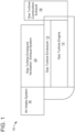
- FIG. 1 shows a schematic of a gas turbine system 10.
- the gas turbine system 10 includes a gas turbine engine 12, a gas turbine enclosure 14 that houses the gas turbine engine 12, an air intake system 16 that provides filtered air to the gas turbine engine 12 for combustion, a gas turbine combustion exhaust 18 for releasing exhaust gases from the gas turbine engine 12, and a gas turbine enclosure ventilation exhaust system 20 to purge and ventilate heat and exhaust products from the gas turbine engine 12.
- the gas turbine engine 12 can include a compressor, a combustor, and a turbine.
- the compressor can compress an incoming flow of air.
- the compressor can deliver the compressed flow of air to the combustor, where the compressed flow of air mixes with a compressed flow of fuel.
- the combustor can ignite the air/fuel mixture to create a flow of combustion gases.
- the flow of combustion gases can be delivered to the turbine to drive the turbine to produce mechanical work.
- the mechanical work produced in the turbine can drive the compressor and an external load, such as an electrical generator or the like.
- the flow of combustion gases may be exhausted or otherwise disposed by the gas turbine combustion exhaust 18.
- the gas turbine engine 12 can use natural gas, various types of syngas, and/or other types of fuels.
- the gas turbine engine 12 may be any one of a number of different gas turbine engines such as those offered by the General Electric Company.
- the gas turbine engine 12 can include an aeroderivative gas turbine.
- the gas turbine enclosure 14 which encloses the gas turbine engine 12, can isolate the gas turbine engine 12.
- the gas turbine enclosure 14 can include a number of different components that operate in conjunction with the gas turbine 12.
- the gas turbine enclosure 14 can include piping for lube oil, NOx emissions, power augmentation, and the like.
- Other components can include, but are not limited to, a gas detection system and a fire detection and suppression system.
- the gas turbine enclosure 14 can perform a number of different functions that contribute to the operation of the gas turbine engine 12.
- the gas turbine enclosure 14 can serve as a sump for oil leaks from the gas turbine engine 12.
- the air intake system 16 can include an inlet screen or an air filter house that includes one or more filter assemblies having a number of inlet air filters that remove moisture and/or particulate matter (such as dust, dirt, contaminants and/or debris) from intake air channeled for supply to the gas turbine engine 12.
- a clean air duct can receive the filtered air from the air filter house.
- the air in the clean air duct is divided into combustion inlet air that goes to the compressor of the gas turbine engine 12, and ventilation inlet air that is supplied to the gas turbine enclosure 14.
- a combustion inlet air duct can provide the combustion inlet air to the compressor, while a ventilation inlet air bypass conduit can supply the ventilation inlet air to the gas turbine enclosure 14.
- the gas turbine enclosure ventilation exhaust system 20 can include one or more ventilation fans that operate to generate an air flow to purge the gas turbine enclosure 14 of heat and exhaust products from the gas turbine engine 12.
- the gas turbine enclosure ventilation exhaust system 20 can include a damper that controls the flow of air containing the heat and exhaust products from the gas turbine engine 12 and the gas turbine enclosure 14.
- the damper can direct the gas turbine enclosure ventilation exhaust air to the air intake system 16 and/or venting to ambient.
- the gas turbine system 10 can include a number of other components not depicted in FIG. 1 .
- the gas turbine system 10 can include a shaft operatively coupled to the compressor and gas turbine of the gas turbine engine 12. To this extent, the shaft may be connected to an electrical generator for power generation applications.
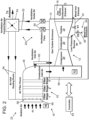
- FIG. 2 shows a schematic of a system 22 for controlling low pressure recoup air vented from the gas turbine engine 12 disposed in the gas turbine enclosure 14 with low pressure recoup air piping 24 coupled to the gas turbine combustion exhaust 18.
- the gas turbine engine 12 is disposed in the gas turbine enclosure 14.
- the gas turbine engine 12 includes a compressor 26, a combustor 28, and a turbine 30.
- the compressor 26 can compress the air received from the air intake system 16.
- the combustor 28 receives a mix of the compressed air from the compressor 26 with fuel for combustion thereof.
- one or more fuel nozzles can intake and mix the fuel with the compressed air from the compressor 26 and distribute the air-fuel mixture into the combustor 28 in a suitable ratio for combustion.
- the air-fuel mixture combusts in a chamber within the combustor 28 to create hot pressurized exhaust gases.
- the exhaust gases from the combustor 28 can be directed towards the turbine 30.
- the shaft can be connected to various components of the gas turbine engine 12, including the compressor 26.
- the compressor 26 also includes blades coupled to the shaft. To this extent, as the shaft rotates, the blades within the compressor 26 also rotate, thereby compressing the air intake from the air intake system 16 through the compressor 26 and into the fuel nozzles and the combustor 28.
- the shaft may also be connected to a load, such as an electrical generator. In this manner, the mechanical work in the turbine 30 can drive the electrical generator to produce power.
- the low pressure recoup air piping 24 can capture and reroute the low pressure recoup air from the gas turbine engine 12.
- the low pressure recoup air piping 24 is in fluid communication with the compressor 26, the gas turbine combustion exhaust 18, which vents the exhaust gases from the turbine 30, and the gas turbine enclosure 14 in which the gas turbine engine 12 is disposed.
- the term "in fluid communication" means that there is a passage that allows a fluid to flow.
- the low pressure recoup air piping 24 can direct the low pressure recoup air towards the gas turbine combustion exhaust 18 and/or into the gas turbine enclosure 14.
- the low pressure recoup air piping 24 can bleed the low pressure recoup air into the gas turbine combustion exhaust 18 and/or into the gas turbine enclosure 14.
- the low pressure recoup air piping 24 can include a first valve V1 operatively coupled to the low pressure recoup air piping 24 to control a flow of the low pressure recoup air from the gas turbine engine 12 to the gas turbine combustion exhaust 18.
- the low pressure recoup air piping 24 can further include a second valve V2 operatively coupled to the low pressure recoup air piping 24 for diverting the low pressure recoup air to the gas turbine enclosure.
- the first valve V1 and the second valve V2 can include any one of number of flow control valves.
- the first valve V1 and the second valve V2 can include electronic flow control values.
- the first valve V1 and the second valve V2 can include solenoid operated valves.
- the low pressure recoup air piping 24 can further include the respective piping to carry the low pressure recoup air from the gas turbine engine 12 into the gas turbine combustion exhaust 18 and the gas turbine enclosure 14.
- the low pressure recoup air piping 24 can include a low pressure recoup air conduit 32, a gas turbine combustion exhaust low pressure recoup air conduit 34, and a gas turbine enclosure low pressure recoup air conduit 36.
- the low pressure recoup air piping 32 is in fluid communication with the gas turbine engine 12 (e.g., the compressor 26) and the first valve V1 and the second valve V2.
- the gas turbine combustion exhaust low pressure recoup air conduit 34 is in fluid communication with the gas turbine combustion exhaust 18 and the first valve V1.
- the gas turbine enclosure low pressure recoup air conduit 36 is in fluid communication with the gas turbine enclosure 14 and the second valve V2.
- the low pressure recoup air conduit 32 can carry the low pressure recoup air towards the first valve V1 and the second valve V2
- the gas turbine combustion exhaust low pressure recoup air conduit 34 can carry the low pressure recoup air from the first valve V1 towards the gas turbine combustion exhaust 18, while the gas turbine enclosure low pressure recoup air conduit 36 can carry the low pressure recoup air from the second valve V2 towards the gas turbine enclosure 14.
- the gas turbine enclosure low pressure recoup air conduit 36 can be configured as a low pressure recoup air dispersion nozzle 38 with a multitude of dispersion holes 40 to deliver the low pressure recoup air into the gas turbine enclosure 14.
- the low pressure recoup air dispersion nozzle 38 with the multitude of dispersion holes 40 can deliver the low pressure recoup air into the gas turbine enclosure 14 in a broad, diverse pattern that precludes splashing of the low pressure recoup air at high velocities.
- the low pressure recoup air dispersion nozzle 38 with the multitude of dispersion holes 40 serves to smoothly distribute or mix the low pressure recoup air in the gas turbine enclosure 14.
- the air intake system 16 can include an air filter house 42 that removes moisture and/or particulate matter (such as dust and/or debris) from intake air 44 channeled to the gas turbine engine 12.
- the air filter house 42 can include a multiple of filter stages (e.g., Filter Stage 1, Filter Stage 2, Filter Stage 3) to filter the intake air 44 provided to the gas turbine engine 12. As shown in FIG.
- the filter stages can be disposed in series in the air filter house 42 such that Filter Stage 1 applies a first filter to the intake air 44, while Filter Stage 2, which is downstream of Filter Stage 1, and Filter Stage 3, which is downstream of Filter Stage 2, each applies an additional filtering of the intake air 44 to further remove any moisture and/or particulate matter that may remain after filtering in the filter stage upstream therefrom.
- downstream and upstream are terms that indicate a direction relative to the flow of a fluid, such as the working fluid through the gas turbine system, for example, the flow of air through the air intake system or through one of the components of a gas turbine engine.
- the term “downstream” corresponds to the direction of flow of the fluid
- upstream refers to the direction opposite to the flow.
- the air filter house 42 can be configured to include other filtering components and is not meant to be limited to the use of fabric filters in the various filter stages.
- the air filter house 42 can include vane filters (e.g., weather hoods and/or screens) to remove and/or filter out large particles and/or debris that may be found in the intake air 44.
- the air filter house 42 can be configured with vane filters formed at an inlet that receives the intake air 44 to remove and/or filter out large particles and/or debris, while the Filter Stages 1, 2 and 3 can filter out the smaller or finer particles that remain in the intake air 44.
- the air intake system 16 further includes a clear air duct 46 in fluid communication with the air filter house 42.
- the clean air duct 46 can receive the filtered air from the air filter house 42.
- the air in the clean air duct 46 is then divided into combustion inlet air that goes to the compressor 26 of the gas turbine engine 12, and ventilation inlet air that is supplied to the gas turbine enclosure 14.
- a combustion inlet air duct 48 that is in fluid communication with the clean air duct 46, provides the combustion inlet air to the compressor 26 of the gas turbine engine 12, while a ventilation inlet air bypass conduit 62, that is in fluid communication with the clean air duct 46, supplies the ventilation inlet air to the gas turbine enclosure 14.
- the clear air duct 46 receives the filtered intake air 44 from the last filter stage (e.g., Filter Stage 3) of the air filter house 42, which the combustion inlet air duct 48 provides as combustion inlet air to the compressor 26, and the ventilation inlet air bypass conduit 62 supplies as ventilation inlet air into the gas turbine enclosure 14.
- the last filter stage e.g., Filter Stage 3
- the combustion inlet air duct 48 provides as combustion inlet air to the compressor 26, and the ventilation inlet air bypass conduit 62 supplies as ventilation inlet air into the gas turbine enclosure 14.
- an inlet screen may be positioned upstream of the air filter house 42, about the inlet that receives the intake air 44, to remove and/or filter out large particles and/or debris, while a silencer assembly formed from a plurality of silencer panels can be located downstream of the air filter house 42, about the clear air duct 46 to reduce the "noise" associated with the intake air 44 transmitted through the air intake system 16.
- the gas turbine enclosure ventilation exhaust system 20 can include one or more ventilation fans 50 to generate an air flow to purge the gas turbine enclosure 14 of heat and exhaust products from the gas turbine engine 12.
- a ventilation conduit 52 in fluid communication with each fan 50, can draw the air flow from the gas turbine enclosure 14 and direct it to a ventilation air control damper 54 as ventilation outlet air.
- the ventilation air control damper 54 which can be an electronically control device, can direct the ventilation outlet air from the gas turbine enclosure 14 to ambient and/or to one or more air inlet heating ducts 56 in fluid communication with a corresponding ventilation conduit 52.
- the air intake system 16 can include a header or manifold 58 that receives the heated air from the gas turbine enclosure ventilation exhaust system 20 via the air inlet heating ducts 56 and distributes the heated air into the flow of intake air 44 entering the air filter house 42.
- the heated air distributed by the header 58 into the intake air 44 increases the temperature of the intake air, thereby providing heat to the air filter house 42, which prevents any ice formation therein that can lead to ice debris and turbine blade damage, as well as a loss of performance if not mitigated.
- the header 58 can include a multiple of ventilation air dispersion nozzles 60 to distribute the heated air from the gas turbine enclosure ventilation exhaust system 20 via the air inlet heating ducts 56 into the flow of intake air 44.
- the multiple ventilation air dispersion nozzles 60 can distribute the heated air into the flow of intake air 44 in a broad pattern. It is understood that the ventilation air dispersion nozzles 60 is one type of distribution pipes that can be used to inject the heated air from the air inlet heating ducts 56 into the flow of intake air 44, and is not meant to be limiting.
- the system 22 of FIG. 2 includes a controller 64 that is operatively coupled with the valves (Valve 1 and Valve 2) associated with the low pressure recoup air piping 24, the ventilation air control damper 54, and the ventilation fans 50.
- the controller 64 can control the operation of Valve 1, Valve 2, the ventilation air control damper 54, and the ventilation fans 50 as a function of one or more conditions detected about the gas turbine engine 12, the air intake system 16, and the gas turbine enclosure ventilation exhaust system 20.
- one or more sensors may be disposed about the gas turbine engine 12, the air intake system 16, and the gas turbine enclosure ventilation exhaust system 20 to detect any of a number of conditions.
- the sensors can be in communication with the controller 64 to provide measurements representative of any number of parameters that the sensors are configured to detect.
- one or more temperature sensors can be disposed about the air intake system 16 to obtain temperature measurements about the air intake system.
- an ambient temperature sensor T0 can be disposed about the inlet of the air intake system 16, while an air intake system temperature sensor T2 can be disposed within the air intake system.
- the ambient temperature sensor T0 can obtain ambient temperature measurements about the inlet of the air intake system 16
- the air intake system temperature sensor T2 can obtain temperature measurements within the air intake system.
- the air intake system temperature sensor T2 can be disposed about the combustion inlet air duct 48. It is understood that temperature sensors can be placed in different locations within the air intake system 16, or alternatively in other locations within the air intake system in addition to temperature sensors T0 and T2.
- temperature sensors can be disposed in other locations in addition to those mentioned for the air intake system 16.
- temperature sensors can be disposed in the gas turbine engine 12, the gas turbine enclosure 14 and the gas turbine enclosure ventilation exhaust system 20.
- sensors can be deployed about the gas turbine engine 12, the gas turbine enclosure 14, the air intake system 16, and the gas turbine enclosure ventilation exhaust system 20.
- sensors that are suitable for use with the gas turbine engine 12, the gas turbine enclosure 14, the air intake system 16, and the gas turbine enclosure ventilation exhaust system 20 include pressure sensors, flow sensors, and humidity sensors.
- the controller 64 can automatically control the flow of the low pressure recoup air from the low pressure recoup air piping 24 to the gas turbine combustion exhaust 18 and/or the gas turbine enclosure 14 and eventually the air intake system 16 as a function of a first temperature measurement representative of ambient temperature about the air intake system 16 obtained by temperature sensor T0, a second temperature measurement obtained within the air intake system by the air intake temperature sensor T2, and a predetermined temperature requirement having an ambient temperature constraint and an air intake system temperature differential constraint.
- the controller 64 can control the flow of the low pressure recoup air from the low pressure recoup air piping 24 to the gas turbine combustion exhaust 18 and/or the air intake system 16 based on values of the first temperature measurement and the second temperature measurement in relation to satisfying the ambient temperature constraint and the air intake system temperature differential constraint.
- the ambient temperature constraint can include an ambient temperature that is less than about 40 degrees Fahrenheit (F) (4.4°C), and the air intake system temperature differential constraint can include a temperature difference between 40 degrees F (4.4°C) and an instant second temperature measurement obtained at T2 or a 10 degree F (5.6°C) increase from the instant second temperature measurement, whichever is lower.
- the valving Valve 1 and Valve 2
- the ventilation air control damper 54 to heat the air intake system 16, as a function of the predetermined temperature requirement is discussed below.
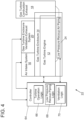
- FIG. 4 shows a schematic block diagram of the system 22 depicted in FIG. 2 with further details of the control logic of the controller 64 that can control the low pressure recoup air vented from the gas turbine engine 12 by the low pressure recoup air piping 24 according to an embodiment of the invention.
- the controller 64 can automatically control the flow of the low pressure recoup air in the low pressure recoup air piping 24 to the gas turbine combustion exhaust 18 and/or the gas turbine enclosure 14.
- controller 64 can use the flow of the low pressure recoup air in the low pressure recoup air piping 24 to aid in heating the air intake system 16 for purposes of preventing icing when the ambient temperatures about the gas turbine engine 12 are prone to icing and subsequent performance issues and other issues including, but not limited to, damage of gas turbine engine components.
- controller 64 can use ambient temperature measurements (T0) located about the air intake system 16, and air intake system temperature measurements (T2), along with the aforementioned predetermined temperature requirement to control how the air intake system 16 is heated to remove or mitigate the icing conditions.
- the controller 64 can use the heated air from the gas turbine enclosure ventilation exhaust system 20 to heat the air intake system 16 according to the underlying objective associated with the predetermined temperature requirement.
- controller 64 When controller 64 senses an improvement in ambient temperature as measured by T0, then the controller can slowly revert the Valve 1, Valve 2 and the ventilation air control damper 54 back to their original positions.
- an "improvement in ambient temperature” means temperature above 40 degrees F, where icing temperatures begin.
- FIG. 4 shows a schematic representation of the control logic that the controller 64 can use to perform the above-described operations.
- the control logic refers to the instructions stored on a non-transitory tangible computer readable medium that enable the controller 64 to perform the various operations associated with controlling the gas turbine engine 12, air intake system 16 and the gas turbine enclosure ventilation exhaust system 20 and their respective components.
- the controller 64 can include turbine operation logic 66, low pressure recoup piping logic 68, and ventilation logic 70.
- the low pressure recoup piping logic 68 can include logic that is configured to control the opening and closing of the valving (Valve 1 and Valve 2) associated with the low pressure recoup piping 24.
- this logic can include modulating (gradually opening or closing) Valve 1 and Valve 2 between fully opened (100%) and fully closed (0)%) positions.
- the ventilation logic 70 can include logic that is configured to control the positioning of the ventilation air control damper 54.
- this logic can include modulating (gradually opening or closing) the ventilation air control damper 54 between positions that fully direct the heated air from the gas turbine enclosure 14 to ambient, to positions that fully direct the heated air from the gas turbine enclosure 14 into the air inlet heating ducts 56 and the air intake system 16, to positions that divert the heated air to both ambient and the air intake system.
- the ventilation logic 70 can include other logic that is directed to other operations performed by the gas turbine enclosure ventilation exhaust system 20.
- the ventilation logic 70 can include logic configured to activate the one or more ventilation fans 50 to purge the gas turbine enclosure 14, as well as logic configured to deactivate the one or more ventilation fans 50 after a purge operation.
- the controller 64 may be coupled to one or more actuators or drives, which in turn, can be coupled to the Valve V1, the Valve V2, and the ventilation air control damper 54.
- the actuators or drives can be configured to drive the Valve V1, the Valve V2, and the ventilation air control damper 54 to positions that correspond with the positions dictated by the corresponding control logic.
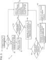
- FIG. 5 shows a flow chart 72 describing the operations associated with the control logic of the controller depicted in FIG. 4 , for controlling the flow of the low pressure recoup air from the low pressure recoup air piping 24 to the gas turbine combustion exhaust 18 and/or to the gas turbine enclosure 14 for eventual heating of the air intake system 16.
- the flow chart 72 of FIG. 5 starts at 74 where the T0 sensor obtains an ambient temperature measurement about the air intake system 16, and the T2 sensor obtains an air intake system temperature measurement within the air intake system.
- the controller 64 can direct the low pressure recoup air in the low pressure recoup air piping 24 to the gas turbine combustion exhaust 18, and the ventilated heated exhaust air from the gas turbine enclosure 14 to ambient at 78.
- the controller 64 can direct valve V1 to be 100% open and the valve V2 to be 0% open (i.e., closed) in order to direct the low pressure recoup air to the gas turbine combustion exhaust 18, while also directing the ventilation air control damper 54 to direct 100% of the ventilated heated exhaust air from the gas turbine enclosure 14 to ambient.
- the controller 64 will direct the gas turbine enclosure ventilation exhaust system 20 to modulate the ventilation air control damper 54 at 80 to direct the gas turbine enclosure ventilation exhaust air towards the air inlet heating ducts 56 and the air intake system 16. This includes moving the ventilation air control damper 54 from a position that moves 0% of the gas turbine enclosure ventilation exhaust air to the air intake system 16 via the air inlet heating ducts 56, to a position that moves 100% of the gas turbine enclosure ventilation exhaust air to air filter house 42 of the air intake system 16.
- the controller 64 can then monitor the effect that modulating the ventilation air control damper 54 from a position that moves 0% of the gas turbine enclosure ventilation exhaust air to the air intake system 16 to a position that moves 100% of the gas turbine enclosure ventilation exhaust air to the air intake system 16 by obtaining additional ambient temperature measurements about the air intake system and temperature measurements within the air intake system. As shown in FIG. 5 , the controller 64 monitors temperature measurements from the T0 and T2 sensors at 82.
- the control logic of the controller 64 will compare these temperature measurements to the temperature constraint and the air intake system temperature differential constraint of the predetermined temperature requirement.
- the temperature constraint comprises an ambient temperature that is less than about 40 degrees F (4.4°C)
- the air intake system temperature differential constraint comprises a temperature difference between 40 degrees F (4.4°C) and the air intake system temperature measurement, or a 10 degree F (5.6°C) increase or rise from the air intake system temperature measurement, whichever is lower.
- an instant air intake system temperature measurement is 32 degrees F (0°C)
- an 8 degrees F (4.4°C) rise e.g., in the air intake system
- the 8 degrees F rise from 32 degrees F to 40 degrees F is less than a 10 degrees F rise or increase from 32 degrees F reading.
- a 10 degrees F rise to 25 degrees F would satisfy the objective of the air intake system temperature differential constraint (i.e., the 10 degrees F rise to 25 degrees is less than the 15 degrees F from 25 degrees F to 40 degrees F).
- the controller 64 can modulate valve V2 at 86 to achieve the underlying objective of the air intake system temperature differential constraint.
- the controller 64 can gradually open the Valve V2 associated with the low pressure recoup air piping 24 to move it from a position in which Valve V2 is 0% open, to a position that is 100% open in order to divert a portion of the flow of the low pressure recoup air to the gas turbine enclosure.
- the gas turbine enclosure ventilation exhaust system 20 can use the ventilation exhaust air from the gas turbine enclosure 14, that will now include the diverted low pressure recoup air, and direct it to the air intake system 16 via the air inlet heating ducts 56.
- the heat from the gas turbine enclosure ventilation exhaust air and the low pressure recoup air will heat the ambient air entering into the air intake system 16 via the air filter house 42.
- the controller 64 can modulate or gradually close the Valve V1 associated with the low pressure recoup air piping at 90 to be 0% open.
- the temperature of the ventilation exhaust air from the gas turbine enclosure 14 should increase because no flow of the low pressure recoup air is being directed out to ambient through the gas turbine combustion exhaust 18.
- the increased heat from the gas turbine enclosure ventilation exhaust air will provide more heat to the ambient air entering into the air intake system 16 via the air filter house 42.
- the controller 64 will modulate Valves V1 and V2 and the ventilation air control damper 54 to slowly revert back to their original positions (Valve 1 - 100% open, Valve 2 -0% open, and damper directing 100% to ambient) at 92.
- the controller 64 can direct the low pressure recoup air piping 24 to supply the low pressure recoup air to the gas turbine combustion exhaust 18, and the ventilation air control damper 54 to direct the gas turbine enclosure ventilation exhaust air to ambient.
- the algorithm embodied by the flow chart 72 depicted in FIG. 5 is amenable for industrial application in that it relates to the technical field of gas turbine systems and presents a solution to a technical problem that temperatures that lead to icing conditions can have on the operation and performance of various components including, but not limited to, the air intake system and the gas turbine engine.
- the algorithm embodied by the flow chart 72 of FIG. 5 can be used for preventing icing in the air intake system 16, including components such as the air filter house 42, in response to the existence of temperatures in which icing can occur.
- the heat from the gas turbine enclosure ventilation exhaust air and/or the diverted low pressure recoup air can heat the air intake system 16 to a temperature that satisfies a predetermined temperature requirement that fulfills an anti-icing objective.
- the low pressure recoup air is vented into the gas turbine enclosure 14 at cold ambient conditions, and the gas turbine enclosure ventilation exhaust system 20 can use this to supplement the heat in the enclosure from the exhaust products of the gas turbine engine 12 and enclosure for preventing icing in the inlet region of the air intake system 16.
- the algorithm can be used to heat the gas turbine enclosure 14 in colder ambient conditions
- the low pressure recoup piping can direct the low pressure recoup air to the gas turbine combustion exhaust 18, and the gas turbine enclosure ventilation exhaust air can be directed to ambient. With the approach described herein, the amount of heated air in the gas turbine enclosure 14 and the gas turbine combustion exhaust 18 can be automatically controlled based on need.
- the system depicted in FIGS. 1 , 2 and 4 may include the necessary electronics, software, memory, storage, databases, firmware, logic/state machines, microprocessors, communication links, displays or other visual or audio user interfaces, printing devices, and any other input/output interfaces to perform the functions described herein and/or to achieve the results described herein, which may be accomplished in real-time.
- the controller 64 depicted in FIGS. 2 and 4 may include at least one processor and system memory / data storage structures, which may include random access memory (RAM) and read-only memory (ROM).
- the at least one processor of the controller 64 may include one or more conventional microprocessors and one or more supplementary co-processors such as math co-processors or the like.
- the data storage structures discussed herein may include an appropriate combination of magnetic, optical and/or semiconductor memory, and may include, for example, RAM, ROM, flash drive, an optical disc such as a compact disc and/or a hard disk or drive.
- a software application that adapts the controller 64 to perform the operations disclosed herein may be read into a main memory of the at least one processor from a computer-readable medium.
- the term "computer-readable medium,” as used herein, refers to any medium that provides or participates in providing instructions to the at least one processor of the controller 64 (or any other processor of a device described herein) for execution. Such a medium may take many forms, including but not limited to, non-volatile media and volatile media.
- Non-volatile media include, for example, optical, magnetic, or opto-magnetic disks, such as memory.
- Volatile media include dynamic random-access memory (DRAM), which typically constitutes the main memory.
- Computer-readable media include, for example, a floppy disk, a flexible disk, hard disk, magnetic tape, any other magnetic medium, a CD-ROM, DVD, any other optical medium, a RAM, a PROM, an EPROM or EEPROM (electronically erasable programmable read-only memory), a FLASH-EEPROM, any other memory chip or cartridge, or any other medium from which a computer can read.
Landscapes
- Engineering & Computer Science (AREA)
- Chemical & Material Sciences (AREA)
- Combustion & Propulsion (AREA)
- Mechanical Engineering (AREA)
- General Engineering & Computer Science (AREA)
- Physics & Mathematics (AREA)
- Fluid Mechanics (AREA)
- Control Of Turbines (AREA)
- Supercharger (AREA)
Claims (13)
- System (22), umfassend:ein Gasturbinengehäuse (14);einen Gasturbinenmotor (12), der in dem Gasturbinengehäuse (14) angeordnet ist;ein Lufteinlasssystem (16), das mit dem Gasturbinengehäuse (14) wirkgekoppelt ist, um Luft zu dem Gasturbinenmotor (12) zu lenken, wobei das Lufteinlasssystem (16) ein Luftfiltergehäuse (42) einschließt, um die Luft, die zu dem Gasturbinenmotor (12) gelenkt wird, zu filtern;einen Gasturbinenverbrennungsauslass (18), der mit dem Gasturbinenmotor (12) wirkgekoppelt ist, um einen Abgasstrom, der von dem Gasturbinenmotor (12) erzeugt wird, außerhalb des Gasturbinengehäuses (14) auszustoßen;eine Niederdruck-Rückgewinnungsluftleitung (24), die mit dem Gasturbinenmotor (12), dem Gasturbinengehäuse (14) und dem Gasturbinenverbrennungsauslass (18) wirkgekoppelt ist, um Niederdruck-Rückgewinnungsluft, die von dem Gasturbinenmotor (12) ausgetrieben wird, dem Gasturbinenverbrennungsauslass (18) und/oder dem Gasturbinengehäuse (14) bereitzustellen;ein erstes Ventil (V1), das mit der Niederdruck-Rückgewinnungsluftleitung (24) wirkgekoppelt ist, um einen Strom der Niederdruck-Rückgewinnungsluft zu dem Gasturbinenverbrennungsauslass (18) zu steuern;ein zweites Ventil (V2), das mit der Niederdruck-Rückgewinnungsluftleitung (24) zum Umleiten der Niederdruck-Rückgewinnungsluft von der Niederdruck-Rückgewinnungsluftleitung (24) zu dem Gasturbinengehäuse (14) wirkgekoppelt ist; undeine Steuervorrichtung (64), die mit dem ersten Ventil und dem zweiten Ventil wirkgekoppelt ist, um den Strom der Niederdruck-Rückgewinnungsluft von der Niederdruck-Rückgewinnungsluftleitung (24) zu dem Gasturbinenverbrennungsauslass (18) und/oder dem Gasturbinengehäuse (14) zu steuern, wobei die Steuervorrichtung (64) eine Steuerlogik einschließt, die konfiguriert ist, um den Strom der Niederdruck-Rückgewinnungsluft in Abhängigkeit von einer Umgebungstemperaturmessung, die um des Lufteinlasssystem (16) herum erhalten wird, einer Lufteinlasssystemtemperaturmessung, die innerhalb des Lufteinlasssystems (16) erhalten wird, und einer zuvor bestimmten Temperaturanforderung, die eine Umgebungstemperaturbeschränkung und eine Lufteinlasssystemtemperaturdifferenzbeschränkung aufweist, zu steuern, wobei die Steuerlogik konfiguriert ist, um den Strom der Niederdruck-Rückgewinnungsluft von der Niederdruck-Rückgewinnungsluftleitung (24) zu dem Gasturbinenverbrennungsauslass (18) und/oder dem Gasturbinengehäuse (14) basierend auf Werten der Umgebungstemperaturmessung und der Lufteinlasssystemtemperaturmessung in Bezug auf ein Erfüllen der Umgebungstemperaturbeschränkung und der Verbrennungslufteinlasssystemtemperaturdifferenzbeschränkung zu steuern.
- System (22) nach Anspruch 1, wobei die Steuerlogik konfiguriert ist, um, als Reaktion darauf, dass die Lufteinlasssystemtemperaturmessung die Umgebungstemperaturbeschränkung erfüllt, das erste Ventil (V1) und das zweite Ventil (V2) zu steuern, um den Strom der Niederdruck-Rückgewinnungsluft von der Niederdruck-Rückgewinnungsluftleitung (24) zu dem Gasturbinenverbrennungsauslass (18) zu lenken.
- System (22) nach Anspruch 1, wobei die Steuerlogik konfiguriert ist, um, als Reaktion auf ein Bestimmen, dass die Lufteinlasssystemtemperaturmessung sowohl die Umgebungstemperaturbeschränkung als auch die Verbrennungslufteinlasssystemtemperaturdifferenzbeschränkung nicht erfüllt, das erste Ventil (V1) und das zweite Ventil (V2) zu steuern, um mindestens einen Anteil des Stroms der Niederdruck-Rückgewinnungsluft zu dem Gasturbinenverbrennungsauslass (14) zu lenken.
- System (22) nach Anspruch 3, wobei die Steuerlogik konfiguriert ist, um das zweite Ventil (V2) von einer 0 % offenen Position in eine 100 % offene Position zu modulieren, um die Verbrennungslufteinlasssystemtemperaturdifferenzbeschränkung zu erfüllen.
- System (22) nach Anspruch 4, wobei die Steuerlogik konfiguriert ist, um das erste Ventil (V1) von einer 100 % offenen Position in eine 0 % offene Position zu modulieren, um die Verbrennungslufteinlasssystemtemperaturdifferenzbeschränkung zu erfüllen.
- System (22) nach Anspruch 5, wobei die Steuerlogik konfiguriert ist, um, als Reaktion auf eine Feststellung, dass die Umgebungstemperaturmessung den zuvor bestimmten Umgebungstemperaturschwellenwert erfüllt, das erste Ventil (V1) und das zweite Ventil (V2) zu steuern, um den Strom der Niederdruck-Rückgewinnungsluft von dem Gasturbinengehäuse (14) graduell weg und in Richtung des Gasturbinenverbrennungsauslasses (18) zu lenken.
- System (22) nach Anspruch 1, ferner umfassend:
ein Gasturbinengehäusebelüftungsauslasssystem (20), das mit dem Lufteinlasssystem (16), dem Gasturbinenmotor (12) und dem Gasturbinengehäuse (14) wirkgekoppelt ist, um Wärme- und Abgasprodukte aus dem Gasturbinenmotor (12) zu spülen und zu belüften, wobei das Gasturbinengehäusebelüftungsauslasssystem (20) eine Belüftungsluftsteuerklappe (54) einschließt, die konfiguriert ist, um Belüftungsauslassluft aus dem Gasturbinengehäuse (14) in die Umgebung und/oder zum Luftfiltergehäuse (42) zu lenken. - System (22) nach Anspruch 7, wobei die Steuerlogik konfiguriert ist, um einen Strom der Belüftungsauslassluft in die Umgebung und/oder zu dem Luftfiltergehäuse (42) zu steuern.
- System (22) nach Anspruch 8, wobei die Steuerlogik konfiguriert ist, um den Strom der Belüftungsauslassluft in die Umgebung und/oder zu dem Luftfiltergehäuse (42) in Abhängigkeit von der Umgebungstemperaturmessung, der Lufteinlasssystemtemperaturmessung und der zuvor bestimmten Temperaturanforderung zu steuern.
- System (22) nach Anspruch 9, wobei die Steuerlogik konfiguriert ist, um eine oder mehrere der Belüftungsauslassluft von dem Gasturbinengehäusebelüftungsauslasssystem (20) und die Niederdruck-Rückgewinnungsluft von dem Gasturbinengehäuse (12) zu dem Luftfiltergehäuse (42) zu lenken, um eine Erfüllung der Lufteinlasssystemtemperaturdifferenzbeschränkung und der zuvor bestimmten Temperaturanforderung zu erreichen.
- System (22) nach Anspruch 10, wobei die Steuerlogik konfiguriert ist, um einen Betrieb des ersten Ventils (V1), des zweiten Ventils (V2) und der Belüftungsluftsteuerklappe (54) graduell zu steuern, um, als Reaktion auf das Bestimmen einer Verbesserung der Umgebungstemperatur in Bezug auf die Umgebungstemperaturbeschränkung in ihre ursprünglichen Betriebspositionen zurückzukehren.
- Verfahren zum Steuern von Niederdruck-Rückgewinnungsluft, die von einem Gasturbinenmotor (12), der in einem Gasturbinengehäuse (14) angeordnet ist, mit einer Niederdruck-Rückgewinnungsluftleitung (24) ausgetrieben wird, die mit einem Gasturbinenverbrennungsauslass (18), der sich außerhalb des Gehäuses befindet, einem Lufteinlasssystem (16), um dem Gasturbinenmotor (12) Luft für Verbrennung bereitzustellen, und einem Gasturbinengehäusebelüftungsauslasssystem (20), um Wärme- und Abgasprodukte aus dem Gasturbinenmotor (12) zu spülen und zu belüften, gekoppelt ist, das Verfahren umfassend:Konfigurieren eines ersten Ventils (V1), um es mit der Niederdruck-Rückgewinnungsluftleitung (24) zusammenwirkend zu betreiben, um einen Strom der Niederdruck-Rückgewinnungsluft zu dem Gasturbinenverbrennungsauslass (18) zu steuern;Konfigurieren eines zweiten Ventils (V2), um es mit der Niederdruck-Rückgewinnungsluftleitung (24) zusammenwirkend zu betreiben zum Umleiten der Niederdruck-Rückgewinnungsluft von der Niederdruck-Rückgewinnungsluftleitung (24) zu dem Gasturbinengehäuse (14);Erhalten einer Umgebungstemperaturmessung um das Lufteinlasssystem (16) herumErhalten einer Lufteinlasssystemtemperaturmessung von innerhalb des Lufteinlasssystems; undSteuern des Stroms der Niederdruck-Rückgewinnungsluft von der Niederdruck-Rückgewinnungsluftleitung (24) zu dem Gasturbinenverbrennungsauslass (18) und/oder dem Gasturbinengehäuse (14) in Abhängigkeit von der Umgebungstemperaturmessung, der Lufteinlasstemperaturmessung und einer zuvor bestimmten Temperaturanforderung, die eine Umgebungstemperaturbeschränkung und eine Lufteinlasstemperaturdifferenzbeschränkung aufweist, wobei das Steuern des Stroms der Niederdruck-Rückgewinnungsluft von der Niederdruck-Rückgewinnungsluftleitung (24) zu dem Gasturbinenverbrennungsauslass (18) und/oder dem Gasturbinengehäuse (14) auf Werten der Umgebungstemperaturmessung und der Lufteinlasssystemtemperaturmessung in Bezug auf das Erfüllen der Umgebungstemperaturbeschränkung und der Gasturbinenmotortemperaturdifferenzbeschränkung basiert.
- Verfahren nach Anspruch 12, ferner umfassend das Steuern eines Stroms von Belüftungsauslassluft von dem Gasturbinengehäusebelüftungsauslasssystem (20) in die Umgebung und/oder zum dem Lufteinlasssystem (16).
Applications Claiming Priority (1)
| Application Number | Priority Date | Filing Date | Title |
|---|---|---|---|
| US17/400,337 US11643966B2 (en) | 2021-08-12 | 2021-08-12 | System and method for controlling low pressure recoup air in gas turbine engine |
Publications (2)
| Publication Number | Publication Date |
|---|---|
| EP4134532A1 EP4134532A1 (de) | 2023-02-15 |
| EP4134532B1 true EP4134532B1 (de) | 2025-01-29 |
Family
ID=82748592
Family Applications (1)
| Application Number | Title | Priority Date | Filing Date |
|---|---|---|---|
| EP22187148.6A Active EP4134532B1 (de) | 2021-08-12 | 2022-07-27 | System und verfahren zum steuern von niederdruck-rücklaufluft in gasturbinenmotoren |
Country Status (5)
| Country | Link |
|---|---|
| US (1) | US11643966B2 (de) |
| EP (1) | EP4134532B1 (de) |
| JP (1) | JP2023026750A (de) |
| KR (1) | KR20230024842A (de) |
| CN (1) | CN115704338A (de) |
Families Citing this family (1)
| Publication number | Priority date | Publication date | Assignee | Title |
|---|---|---|---|---|
| EP4223986A1 (de) * | 2022-02-07 | 2023-08-09 | Rolls-Royce Deutschland Ltd & Co KG | Turbinengeneratorsystem |
Family Cites Families (12)
| Publication number | Priority date | Publication date | Assignee | Title |
|---|---|---|---|---|
| US9091215B2 (en) | 2011-06-28 | 2015-07-28 | General Electric Company | System for ventilating a gas turbine enclosure |
| US8844258B2 (en) * | 2011-11-23 | 2014-09-30 | General Electric Company | Systems and methods for de-icing a gas turbine engine inlet screen and dehumidifying inlet air filters |
| US20130269355A1 (en) | 2012-04-12 | 2013-10-17 | General Electric Company | Method and system for controlling an extraction pressure and temperature of a stoichiometric egr system |
| US20140020394A1 (en) | 2012-07-20 | 2014-01-23 | General Electric Company | System and method for turbomachine housing ventilation |
| US20140230400A1 (en) * | 2013-02-15 | 2014-08-21 | Kevin M. Light | Heat retention and distribution system for gas turbine engines |
| US20150322866A1 (en) * | 2014-05-12 | 2015-11-12 | General Electric Company | Enhanced Turbine Cooling System Using a Blend of Compressor Bleed Air and Turbine Compartment Air |
| US20150345390A1 (en) | 2014-05-29 | 2015-12-03 | General Electric Company | Systems and methods for de-icing inlet screens and dehumidifying inlet air filters for gas turbine engines |
| US10260371B2 (en) * | 2016-05-20 | 2019-04-16 | Pratt & Whitney Canada Corp. | Method and assembly for providing an anti-icing airflow |
| US20170342902A1 (en) | 2016-05-27 | 2017-11-30 | General Electric Company | System and method of compressor inlet temperature control |
| US11713719B2 (en) * | 2020-05-07 | 2023-08-01 | The Boeing Company | Engine bleed power recovery systems and related methods |
| US11459951B2 (en) * | 2020-12-22 | 2022-10-04 | General Electric Company | Anti-icing system with a flow-deflector assembly |
| CN113153527A (zh) | 2020-12-22 | 2021-07-23 | 中国船舶重工集团公司第七0三研究所 | 一种改进的h-25燃气轮机发电机组ibh系统 |
-
2021
- 2021-08-12 US US17/400,337 patent/US11643966B2/en active Active
-
2022
- 2022-07-07 CN CN202210796290.XA patent/CN115704338A/zh active Pending
- 2022-07-08 JP JP2022110688A patent/JP2023026750A/ja active Pending
- 2022-07-27 EP EP22187148.6A patent/EP4134532B1/de active Active
- 2022-08-05 KR KR1020220097733A patent/KR20230024842A/ko active Pending
Also Published As
| Publication number | Publication date |
|---|---|
| JP2023026750A (ja) | 2023-02-28 |
| US20230046896A1 (en) | 2023-02-16 |
| KR20230024842A (ko) | 2023-02-21 |
| US11643966B2 (en) | 2023-05-09 |
| EP4134532A1 (de) | 2023-02-15 |
| CN115704338A (zh) | 2023-02-17 |
Similar Documents
| Publication | Publication Date | Title |
|---|---|---|
| US9091215B2 (en) | System for ventilating a gas turbine enclosure | |
| US8721753B2 (en) | Method and apparatus for an air filter cartridge replacement assembly | |
| US9399951B2 (en) | Modular louver system | |
| US8257017B2 (en) | Method and device for cooling a component of a turbine | |
| JP2017106444A (ja) | 入口抽気加熱制御システム | |
| EP4134532B1 (de) | System und verfahren zum steuern von niederdruck-rücklaufluft in gasturbinenmotoren | |
| EP4124737B1 (de) | System und verfahren zum verhindern des eindringens von partikeln und fremdkörpern in verbrennungssysteme | |
| EP4202196A1 (de) | System und verfahren zur verhinderung von vereisung im verbrennungseinlassluftweg einer gasturbinenanlage | |
| US9896964B2 (en) | Core case heating for gas turbine engines | |
| US10036321B2 (en) | Systems and methods for utilizing gas turbine compartment ventilation discharge air | |
| US20230111717A1 (en) | Flame detector lens maintenance system | |
| EP2314883A1 (de) | Vorrichtung zur Zufuhr von Luft zu einem Verdichter einer Gasturbine | |
| US11519331B2 (en) | Gas turbine apparatus and manufacturing method for the same, and operation method for gas turbine apparatus | |
| Aamodt | Gas Turbine Operation-Drift av Gassturbiner | |
| WO2018110477A1 (ja) | ガスタービンエンジン | |
| EP3910178A1 (de) | Gasturbine mit filtereinheit | |
| US20170306849A1 (en) | Electronic module location for mechanical components | |
| US20110250046A1 (en) | Turbofan engine performance recovery system and method | |
| JPS6158927A (ja) | ガスタ−ビン用セルフクリ−ニングタイプ空気取入方法 |
Legal Events
| Date | Code | Title | Description |
|---|---|---|---|
| PUAI | Public reference made under article 153(3) epc to a published international application that has entered the european phase |
Free format text: ORIGINAL CODE: 0009012 |
|
| STAA | Information on the status of an ep patent application or granted ep patent |
Free format text: STATUS: THE APPLICATION HAS BEEN PUBLISHED |
|
| AK | Designated contracting states |
Kind code of ref document: A1 Designated state(s): AL AT BE BG CH CY CZ DE DK EE ES FI FR GB GR HR HU IE IS IT LI LT LU LV MC MK MT NL NO PL PT RO RS SE SI SK SM TR |
|
| STAA | Information on the status of an ep patent application or granted ep patent |
Free format text: STATUS: REQUEST FOR EXAMINATION WAS MADE |
|
| 17P | Request for examination filed |
Effective date: 20230630 |
|
| RBV | Designated contracting states (corrected) |
Designated state(s): AL AT BE BG CH CY CZ DE DK EE ES FI FR GB GR HR HU IE IS IT LI LT LU LV MC MK MT NL NO PL PT RO RS SE SI SK SM TR |
|
| RAP1 | Party data changed (applicant data changed or rights of an application transferred) |
Owner name: GENERAL ELECTRIC TECHNOLOGY GMBH |
|
| GRAP | Despatch of communication of intention to grant a patent |
Free format text: ORIGINAL CODE: EPIDOSNIGR1 |
|
| STAA | Information on the status of an ep patent application or granted ep patent |
Free format text: STATUS: GRANT OF PATENT IS INTENDED |
|
| RIC1 | Information provided on ipc code assigned before grant |
Ipc: F02C 7/047 20060101ALI20241003BHEP Ipc: F02C 6/06 20060101ALI20241003BHEP Ipc: F02C 7/24 20060101AFI20241003BHEP |
|
| INTG | Intention to grant announced |
Effective date: 20241011 |
|
| GRAS | Grant fee paid |
Free format text: ORIGINAL CODE: EPIDOSNIGR3 |
|
| GRAA | (expected) grant |
Free format text: ORIGINAL CODE: 0009210 |
|
| STAA | Information on the status of an ep patent application or granted ep patent |
Free format text: STATUS: THE PATENT HAS BEEN GRANTED |
|
| AK | Designated contracting states |
Kind code of ref document: B1 Designated state(s): AL AT BE BG CH CY CZ DE DK EE ES FI FR GB GR HR HU IE IS IT LI LT LU LV MC MK MT NL NO PL PT RO RS SE SI SK SM TR |
|
| REG | Reference to a national code |
Ref country code: GB Ref legal event code: FG4D |
|
| REG | Reference to a national code |
Ref country code: CH Ref legal event code: EP |
|
| REG | Reference to a national code |
Ref country code: DE Ref legal event code: R096 Ref document number: 602022010009 Country of ref document: DE |
|
| REG | Reference to a national code |
Ref country code: IE Ref legal event code: FG4D |
|
| REG | Reference to a national code |
Ref country code: NL Ref legal event code: MP Effective date: 20250129 |
|
| PG25 | Lapsed in a contracting state [announced via postgrant information from national office to epo] |
Ref country code: NL Free format text: LAPSE BECAUSE OF FAILURE TO SUBMIT A TRANSLATION OF THE DESCRIPTION OR TO PAY THE FEE WITHIN THE PRESCRIBED TIME-LIMIT Effective date: 20250129 |
|
| PG25 | Lapsed in a contracting state [announced via postgrant information from national office to epo] |
Ref country code: RS Free format text: LAPSE BECAUSE OF FAILURE TO SUBMIT A TRANSLATION OF THE DESCRIPTION OR TO PAY THE FEE WITHIN THE PRESCRIBED TIME-LIMIT Effective date: 20250429 |
|
| PG25 | Lapsed in a contracting state [announced via postgrant information from national office to epo] |
Ref country code: FI Free format text: LAPSE BECAUSE OF FAILURE TO SUBMIT A TRANSLATION OF THE DESCRIPTION OR TO PAY THE FEE WITHIN THE PRESCRIBED TIME-LIMIT Effective date: 20250129 |
|
| PG25 | Lapsed in a contracting state [announced via postgrant information from national office to epo] |
Ref country code: PL Free format text: LAPSE BECAUSE OF FAILURE TO SUBMIT A TRANSLATION OF THE DESCRIPTION OR TO PAY THE FEE WITHIN THE PRESCRIBED TIME-LIMIT Effective date: 20250129 |
|
| PG25 | Lapsed in a contracting state [announced via postgrant information from national office to epo] |
Ref country code: ES Free format text: LAPSE BECAUSE OF FAILURE TO SUBMIT A TRANSLATION OF THE DESCRIPTION OR TO PAY THE FEE WITHIN THE PRESCRIBED TIME-LIMIT Effective date: 20250129 |
|
| REG | Reference to a national code |
Ref country code: LT Ref legal event code: MG9D |
|
| PG25 | Lapsed in a contracting state [announced via postgrant information from national office to epo] |
Ref country code: NO Free format text: LAPSE BECAUSE OF FAILURE TO SUBMIT A TRANSLATION OF THE DESCRIPTION OR TO PAY THE FEE WITHIN THE PRESCRIBED TIME-LIMIT Effective date: 20250429 Ref country code: IS Free format text: LAPSE BECAUSE OF FAILURE TO SUBMIT A TRANSLATION OF THE DESCRIPTION OR TO PAY THE FEE WITHIN THE PRESCRIBED TIME-LIMIT Effective date: 20250529 |
|
| REG | Reference to a national code |
Ref country code: AT Ref legal event code: MK05 Ref document number: 1763641 Country of ref document: AT Kind code of ref document: T Effective date: 20250129 |
|
| PG25 | Lapsed in a contracting state [announced via postgrant information from national office to epo] |
Ref country code: HR Free format text: LAPSE BECAUSE OF FAILURE TO SUBMIT A TRANSLATION OF THE DESCRIPTION OR TO PAY THE FEE WITHIN THE PRESCRIBED TIME-LIMIT Effective date: 20250129 |
|
| PG25 | Lapsed in a contracting state [announced via postgrant information from national office to epo] |
Ref country code: LV Free format text: LAPSE BECAUSE OF FAILURE TO SUBMIT A TRANSLATION OF THE DESCRIPTION OR TO PAY THE FEE WITHIN THE PRESCRIBED TIME-LIMIT Effective date: 20250129 Ref country code: PT Free format text: LAPSE BECAUSE OF FAILURE TO SUBMIT A TRANSLATION OF THE DESCRIPTION OR TO PAY THE FEE WITHIN THE PRESCRIBED TIME-LIMIT Effective date: 20250529 |
|
| PG25 | Lapsed in a contracting state [announced via postgrant information from national office to epo] |
Ref country code: GR Free format text: LAPSE BECAUSE OF FAILURE TO SUBMIT A TRANSLATION OF THE DESCRIPTION OR TO PAY THE FEE WITHIN THE PRESCRIBED TIME-LIMIT Effective date: 20250430 Ref country code: BG Free format text: LAPSE BECAUSE OF FAILURE TO SUBMIT A TRANSLATION OF THE DESCRIPTION OR TO PAY THE FEE WITHIN THE PRESCRIBED TIME-LIMIT Effective date: 20250129 |
|
| PG25 | Lapsed in a contracting state [announced via postgrant information from national office to epo] |
Ref country code: AT Free format text: LAPSE BECAUSE OF FAILURE TO SUBMIT A TRANSLATION OF THE DESCRIPTION OR TO PAY THE FEE WITHIN THE PRESCRIBED TIME-LIMIT Effective date: 20250129 |
|
| PG25 | Lapsed in a contracting state [announced via postgrant information from national office to epo] |
Ref country code: SE Free format text: LAPSE BECAUSE OF FAILURE TO SUBMIT A TRANSLATION OF THE DESCRIPTION OR TO PAY THE FEE WITHIN THE PRESCRIBED TIME-LIMIT Effective date: 20250129 |
|
| RAP4 | Party data changed (patent owner data changed or rights of a patent transferred) |
Owner name: GE VERNOVA TECHNOLOGY GMBH |
|
| PG25 | Lapsed in a contracting state [announced via postgrant information from national office to epo] |
Ref country code: SM Free format text: LAPSE BECAUSE OF FAILURE TO SUBMIT A TRANSLATION OF THE DESCRIPTION OR TO PAY THE FEE WITHIN THE PRESCRIBED TIME-LIMIT Effective date: 20250129 |
|
| PG25 | Lapsed in a contracting state [announced via postgrant information from national office to epo] |
Ref country code: DK Free format text: LAPSE BECAUSE OF FAILURE TO SUBMIT A TRANSLATION OF THE DESCRIPTION OR TO PAY THE FEE WITHIN THE PRESCRIBED TIME-LIMIT Effective date: 20250129 |
|
| PGFP | Annual fee paid to national office [announced via postgrant information from national office to epo] |
Ref country code: DE Payment date: 20250620 Year of fee payment: 4 |
|
| PGFP | Annual fee paid to national office [announced via postgrant information from national office to epo] |
Ref country code: IT Payment date: 20250731 Year of fee payment: 4 |
|
| PGFP | Annual fee paid to national office [announced via postgrant information from national office to epo] |
Ref country code: CH Payment date: 20250801 Year of fee payment: 4 |
|
| PG25 | Lapsed in a contracting state [announced via postgrant information from national office to epo] |
Ref country code: EE Free format text: LAPSE BECAUSE OF FAILURE TO SUBMIT A TRANSLATION OF THE DESCRIPTION OR TO PAY THE FEE WITHIN THE PRESCRIBED TIME-LIMIT Effective date: 20250129 Ref country code: CZ Free format text: LAPSE BECAUSE OF FAILURE TO SUBMIT A TRANSLATION OF THE DESCRIPTION OR TO PAY THE FEE WITHIN THE PRESCRIBED TIME-LIMIT Effective date: 20250129 |
|
| PG25 | Lapsed in a contracting state [announced via postgrant information from national office to epo] |
Ref country code: RO Free format text: LAPSE BECAUSE OF FAILURE TO SUBMIT A TRANSLATION OF THE DESCRIPTION OR TO PAY THE FEE WITHIN THE PRESCRIBED TIME-LIMIT Effective date: 20250129 |
|
| PG25 | Lapsed in a contracting state [announced via postgrant information from national office to epo] |
Ref country code: SK Free format text: LAPSE BECAUSE OF FAILURE TO SUBMIT A TRANSLATION OF THE DESCRIPTION OR TO PAY THE FEE WITHIN THE PRESCRIBED TIME-LIMIT Effective date: 20250129 |
|
| REG | Reference to a national code |
Ref country code: DE Ref legal event code: R097 Ref document number: 602022010009 Country of ref document: DE |
|
| PLBE | No opposition filed within time limit |
Free format text: ORIGINAL CODE: 0009261 |
|
| STAA | Information on the status of an ep patent application or granted ep patent |
Free format text: STATUS: NO OPPOSITION FILED WITHIN TIME LIMIT |