EP4201752A1 - Collision energy absorption component for automobile, and method for manufacturing said collision energy absorption component for automobile - Google Patents
Collision energy absorption component for automobile, and method for manufacturing said collision energy absorption component for automobile Download PDFInfo
- Publication number
- EP4201752A1 EP4201752A1 EP21857994.4A EP21857994A EP4201752A1 EP 4201752 A1 EP4201752 A1 EP 4201752A1 EP 21857994 A EP21857994 A EP 21857994A EP 4201752 A1 EP4201752 A1 EP 4201752A1
- Authority
- EP
- European Patent Office
- Prior art keywords
- coating
- automotive
- crashworthiness
- energy absorption
- tubular member
- Prior art date
- Legal status (The legal status is an assumption and is not a legal conclusion. Google has not performed a legal analysis and makes no representation as to the accuracy of the status listed.)
- Pending
Links
- 238000010521 absorption reaction Methods 0.000 title claims abstract description 60
- 238000004519 manufacturing process Methods 0.000 title claims description 42
- 238000000034 method Methods 0.000 title claims description 32
- 238000000576 coating method Methods 0.000 claims abstract description 191
- 239000011248 coating agent Substances 0.000 claims abstract description 177
- 238000004070 electrodeposition Methods 0.000 claims abstract description 63
- 239000003973 paint Substances 0.000 claims abstract description 36
- 239000000463 material Substances 0.000 claims abstract description 26
- 239000011247 coating layer Substances 0.000 claims description 21
- 229920001187 thermosetting polymer Polymers 0.000 claims description 5
- 238000012360 testing method Methods 0.000 description 50
- 230000000052 comparative effect Effects 0.000 description 49
- 229910000831 Steel Inorganic materials 0.000 description 34
- 239000010959 steel Substances 0.000 description 34
- 239000006260 foam Substances 0.000 description 16
- 238000005304 joining Methods 0.000 description 15
- 230000000694 effects Effects 0.000 description 14
- 230000001965 increasing effect Effects 0.000 description 13
- 238000013016 damping Methods 0.000 description 11
- 239000002184 metal Substances 0.000 description 11
- 239000004918 carbon fiber reinforced polymer Substances 0.000 description 10
- 230000008569 process Effects 0.000 description 10
- 238000005452 bending Methods 0.000 description 8
- 239000000945 filler Substances 0.000 description 7
- 125000002091 cationic group Chemical group 0.000 description 5
- 230000002787 reinforcement Effects 0.000 description 5
- 229920000877 Melamine resin Polymers 0.000 description 4
- 229920005989 resin Polymers 0.000 description 4
- 239000011347 resin Substances 0.000 description 4
- 238000005316 response function Methods 0.000 description 4
- 229920002430 Fibre-reinforced plastic Polymers 0.000 description 3
- 238000001035 drying Methods 0.000 description 3
- 238000011156 evaluation Methods 0.000 description 3
- 239000000835 fiber Substances 0.000 description 3
- 239000011151 fibre-reinforced plastic Substances 0.000 description 3
- 230000009467 reduction Effects 0.000 description 3
- 238000010998 test method Methods 0.000 description 3
- 239000013585 weight reducing agent Substances 0.000 description 3
- 238000003466 welding Methods 0.000 description 3
- 239000004593 Epoxy Substances 0.000 description 2
- 230000001133 acceleration Effects 0.000 description 2
- 239000000853 adhesive Substances 0.000 description 2
- 230000001070 adhesive effect Effects 0.000 description 2
- 238000004364 calculation method Methods 0.000 description 2
- 239000002131 composite material Substances 0.000 description 2
- 238000000151 deposition Methods 0.000 description 2
- 230000008021 deposition Effects 0.000 description 2
- 238000013461 design Methods 0.000 description 2
- 239000004088 foaming agent Substances 0.000 description 2
- 229920002635 polyurethane Polymers 0.000 description 2
- 239000004814 polyurethane Substances 0.000 description 2
- 238000005482 strain hardening Methods 0.000 description 2
- 238000004381 surface treatment Methods 0.000 description 2
- 230000002889 sympathetic effect Effects 0.000 description 2
- 239000011800 void material Substances 0.000 description 2
- 238000005406 washing Methods 0.000 description 2
- 238000012935 Averaging Methods 0.000 description 1
- 229910000576 Laminated steel Inorganic materials 0.000 description 1
- 238000004458 analytical method Methods 0.000 description 1
- 230000004323 axial length Effects 0.000 description 1
- 230000005540 biological transmission Effects 0.000 description 1
- 238000006243 chemical reaction Methods 0.000 description 1
- 238000004040 coloring Methods 0.000 description 1
- 230000003247 decreasing effect Effects 0.000 description 1
- 238000005238 degreasing Methods 0.000 description 1
- 238000011161 development Methods 0.000 description 1
- 230000018109 developmental process Effects 0.000 description 1
- 230000002708 enhancing effect Effects 0.000 description 1
- 238000002474 experimental method Methods 0.000 description 1
- 238000004880 explosion Methods 0.000 description 1
- 238000005187 foaming Methods 0.000 description 1
- 238000010438 heat treatment Methods 0.000 description 1
- 230000006872 improvement Effects 0.000 description 1
- JEIPFZHSYJVQDO-UHFFFAOYSA-N iron(III) oxide Inorganic materials O=[Fe]O[Fe]=O JEIPFZHSYJVQDO-UHFFFAOYSA-N 0.000 description 1
- 239000010410 layer Substances 0.000 description 1
- 238000003754 machining Methods 0.000 description 1
- 230000000873 masking effect Effects 0.000 description 1
- 238000005457 optimization Methods 0.000 description 1
- 238000010422 painting Methods 0.000 description 1
- 230000002265 prevention Effects 0.000 description 1
- 238000012545 processing Methods 0.000 description 1
- 230000002040 relaxant effect Effects 0.000 description 1
- 230000000452 restraining effect Effects 0.000 description 1
- 238000009751 slip forming Methods 0.000 description 1
- 239000007787 solid Substances 0.000 description 1
- 239000007921 spray Substances 0.000 description 1
- 238000005507 spraying Methods 0.000 description 1
- 238000003892 spreading Methods 0.000 description 1
- 230000007480 spreading Effects 0.000 description 1
- 239000000126 substance Substances 0.000 description 1
- 238000002834 transmittance Methods 0.000 description 1
Images


Classifications
-
- C—CHEMISTRY; METALLURGY
- C25—ELECTROLYTIC OR ELECTROPHORETIC PROCESSES; APPARATUS THEREFOR
- C25D—PROCESSES FOR THE ELECTROLYTIC OR ELECTROPHORETIC PRODUCTION OF COATINGS; ELECTROFORMING; APPARATUS THEREFOR
- C25D13/00—Electrophoretic coating characterised by the process
- C25D13/12—Electrophoretic coating characterised by the process characterised by the article coated
- C25D13/14—Tubes; Rings; Hollow bodies
-
- F—MECHANICAL ENGINEERING; LIGHTING; HEATING; WEAPONS; BLASTING
- F16—ENGINEERING ELEMENTS AND UNITS; GENERAL MEASURES FOR PRODUCING AND MAINTAINING EFFECTIVE FUNCTIONING OF MACHINES OR INSTALLATIONS; THERMAL INSULATION IN GENERAL
- F16F—SPRINGS; SHOCK-ABSORBERS; MEANS FOR DAMPING VIBRATION
- F16F7/00—Vibration-dampers; Shock-absorbers
- F16F7/12—Vibration-dampers; Shock-absorbers using plastic deformation of members
- F16F7/124—Vibration-dampers; Shock-absorbers using plastic deformation of members characterised by their special construction from fibre-reinforced plastics
-
- B—PERFORMING OPERATIONS; TRANSPORTING
- B62—LAND VEHICLES FOR TRAVELLING OTHERWISE THAN ON RAILS
- B62D—MOTOR VEHICLES; TRAILERS
- B62D21/00—Understructures, i.e. chassis frame on which a vehicle body may be mounted
- B62D21/15—Understructures, i.e. chassis frame on which a vehicle body may be mounted having impact absorbing means, e.g. a frame designed to permanently or temporarily change shape or dimension upon impact with another body
-
- B—PERFORMING OPERATIONS; TRANSPORTING
- B60—VEHICLES IN GENERAL
- B60R—VEHICLES, VEHICLE FITTINGS, OR VEHICLE PARTS, NOT OTHERWISE PROVIDED FOR
- B60R19/00—Wheel guards; Radiator guards, e.g. grilles; Obstruction removers; Fittings damping bouncing force in collisions
- B60R19/02—Bumpers, i.e. impact receiving or absorbing members for protecting vehicles or fending off blows from other vehicles or objects
- B60R19/24—Arrangements for mounting bumpers on vehicles
- B60R19/26—Arrangements for mounting bumpers on vehicles comprising yieldable mounting means
- B60R19/34—Arrangements for mounting bumpers on vehicles comprising yieldable mounting means destroyed upon impact, e.g. one-shot type
-
- B—PERFORMING OPERATIONS; TRANSPORTING
- B62—LAND VEHICLES FOR TRAVELLING OTHERWISE THAN ON RAILS
- B62D—MOTOR VEHICLES; TRAILERS
- B62D29/00—Superstructures, understructures, or sub-units thereof, characterised by the material thereof
- B62D29/001—Superstructures, understructures, or sub-units thereof, characterised by the material thereof characterised by combining metal and synthetic material
- B62D29/005—Superstructures, understructures, or sub-units thereof, characterised by the material thereof characterised by combining metal and synthetic material preformed metal and synthetic material elements being joined together, e.g. by adhesives
-
- B—PERFORMING OPERATIONS; TRANSPORTING
- B60—VEHICLES IN GENERAL
- B60Y—INDEXING SCHEME RELATING TO ASPECTS CROSS-CUTTING VEHICLE TECHNOLOGY
- B60Y2306/00—Other features of vehicle sub-units
- B60Y2306/01—Reducing damages in case of crash, e.g. by improving battery protection
-
- B—PERFORMING OPERATIONS; TRANSPORTING
- B62—LAND VEHICLES FOR TRAVELLING OTHERWISE THAN ON RAILS
- B62D—MOTOR VEHICLES; TRAILERS
- B62D21/00—Understructures, i.e. chassis frame on which a vehicle body may be mounted
- B62D21/15—Understructures, i.e. chassis frame on which a vehicle body may be mounted having impact absorbing means, e.g. a frame designed to permanently or temporarily change shape or dimension upon impact with another body
- B62D21/152—Front or rear frames
Landscapes
- Engineering & Computer Science (AREA)
- Mechanical Engineering (AREA)
- Chemical & Material Sciences (AREA)
- Combustion & Propulsion (AREA)
- Transportation (AREA)
- General Engineering & Computer Science (AREA)
- Electrochemistry (AREA)
- Chemical Kinetics & Catalysis (AREA)
- Materials Engineering (AREA)
- Metallurgy (AREA)
- Organic Chemistry (AREA)
- Structural Engineering (AREA)
- Architecture (AREA)
- Body Structure For Vehicles (AREA)
- Laminated Bodies (AREA)
Abstract
Description
- The present invention relates to an automotive crashworthiness energy absorption part and a method for manufacturing the automotive crashworthiness energy absorption part, and more particularly to an automotive crashworthiness energy absorption part that is axially crushed when a crashworthiness load is input from a front side or a rear side of an automotive body to absorb crashworthiness energy, and a method for manufacturing the automotive crashworthiness energy absorption part. Background
- As techniques for improving crashworthiness energy absorptive properties of automobiles, there exist many techniques such as optimization of a shape, a structure, a material, and the like of automotive parts. Moreover, in recent years, many techniques have been proposed to achieve both improvement of crashworthiness energy absorptive properties of automotive parts and weight reduction of automotive bodies, by causing resin to foam and filling the inside of automotive parts having a closed cross section shape.
- For example,
Patent Literature 1 discloses a technique in which, in an automotive structural member having a structure in which a closed space is formed inside by aligning the direction of top portions of hat-shaped cross section parts such as a side sill, a floor member, a pillar, and overlapping flange portions, bending strength and torsional stiffness of the automotive structural member are improved while suppressing an increase in weight by filling the inside with a foam filler, and stiffness and collision safety of the automotive body are improved. - In addition,
Patent Literature 2 discloses a technique in which, when an inner space of a closed cross section shape such as a pillar in which hat-shaped cross section parts face each other and flange portions are combined is filled with a high stiffness foam body, the high stiffness foam body is fixed by compressive counterforce due to filling and foaming of the high stiffness foam body to improve vibration damping performance that suppresses transmission of vibration sound, and improve strength, stiffness, and crashworthiness energy absorptive properties. -
Patent Literature 3 discloses a metal-carbon fiber reinforced plastic (CFRP) composite material in which a reinforcement material formed of CFRP in which a plurality of fiber layers are laminated is adhered to a surface of a metal member with a thermosetting adhesive. The metal-CFRP composite material has a structure that includes a residual shear stress relaxing portion with a thickness gradually decreasing from a main body portion of the reinforcement material toward an outer edge so as to relax the residual shear stress generated in the thermosetting adhesive due to a difference in a coefficient of linear thermal expansion between the metal member and the reinforcement material after adhesion. - Moreover, Patent Literature 4 discloses an automotive part that includes a front side member including: an energy absorption portion formed of fiber reinforced plastic (FRP) having a tubular-shaped cross section that causes sequential axial crush from an input end side by an input load in an axial direction; and a support portion continuously formed with the energy absorption portion and formed of FRP, and joined to automotive parts. The energy absorption portion has reinforcement fibers equally oriented in a longitudinal direction of the front side member and a direction perpendicular to the longitudinal direction, the support portion has reinforcement fibers oriented with isotropy, and the automotive part can be integrally molded.
-
- Patent Literature 1:
JP 2006-240134 A - Patent Literature 2:
JP 2000-318075 A - Patent Literature 3:
JP 2017-61068 A - Patent Literature 4:
JP 2005-271875 A - According to the techniques disclosed in
Patent Literatures - However, for automotive parts such as a front side member and a crash box that absorb crashworthiness energy by buckling deformation in a bellows shape when a crashworthiness load is input from the front side or the rear side of an automobile and causes axial crushing, even when the technique of filling the inside of the automotive part with a foam filler or a foam body is applied, since the foam filler or the foam body is simply filled inside the automotive part, adhesion force between the automotive part and the foam filler or the foaming agent is insufficient. As a result, there has been a problem that the foam filler or foaming agent inside the part blows out through a gap or the like formed in a joining portion of the part at the time of collision, making it difficult to improve crashworthiness energy absorptive properties. In addition, there has also been a problem that an additional process of filling with foam resin without forming any gap is required, and production cost in manufacturing automotive parts increases.
- In addition, according to the techniques disclosed in
Patent Literatures 3 and 4, it is stated that bending strength can be improved by adhering CFRP to the surface of a metal, and a reduction in part assembly man-hours and a reduction in weight increase due to a reduction in the number of fastening parts can be achieved by integrally manufacturing parts in consideration of orientation of CFRP itself. - However, even when CFRP is applied to an axial crush part that involves deformation, CFRP has high strength, but significantly low elongation. Therefore, there has been a problem that break and fracture of CFRP occur as soon as bellows-shaped deformation starts, and crashworthiness energy absorptive properties are not improved. In addition, there has also been a problem that CFRP has a significantly high cost.
- The present invention has been made to solve the above problems, and an object of the present invention is to provide: an automotive crashworthiness energy absorption part such as a front side member and a crash box that, when a crashworthiness load is input from the front side or the rear side of an automotive body and causes axial crushing, improves crashworthiness energy absorbing effect by forming a thick coating film of coating on an outer surface, can function as a vibration-damping material that absorbs vibration generated in the automotive body, and can reduce additional production processes, thus preventing a large increase in the production cost; and a method for manufacturing the automotive crashworthiness energy absorption part.
- The inventors have intensively studied a method for solving the above problems, and have found that it is possible to improve the crashworthiness energy absorbing effect without requiring an additional process of filling with a filler such as foam resin without forming any gap by utilizing an electrodeposition paint, which is generally used in a coating process in automobile manufacturing. The present invention has been made on the basis of such findings, and specifically includes the following configurations.
- An automotive crashworthiness energy absorption part according to the present invention is provided in a front portion or a rear portion of an automotive body, the automotive crashworthiness energy absorption part being axially crushed when a crashworthiness load is input from a front side or a rear side of the automotive body to absorb crashworthiness energy, and includes: a tubular member formed by using a hat-shaped section part including a top portion and a side-wall portion; a coating part made of a material having a lower strength than the tubular member, the coating part being arranged on outer surfaces of the top portion and the side-wall portion at a portion including a corner portion configured to connect the top portion and the side-wall portion, with a gap of 0.2 mm or more and 3 mm or less from the outer surface of the top portion, the outer surface of the side-wall portion, and an outer surface of the corner portion; and a coating film of an electrodeposition paint formed in the gap.
- A method for manufacturing an automotive crashworthiness energy absorption part according to the present invention provided in a front portion or a rear portion of an automotive body, the automotive crashworthiness energy absorption part being axially crushed when a crashworthiness load is input from a front side or a rear side of the automotive body to absorb crashworthiness energy, includes: a part manufacturing step of manufacturing a pre-coated part including: a tubular member formed by using a hat-shaped section part including a top portion and a side-wall portion; and a coating part made of a material having a lower strength than the tubular member, the coating part being arranged on an outer surface of the tubular member at a portion including a corner portion configured to connect the top portion and the side-wall portion, with a gap of 0.2 mm or more and 3 mm or less from an outer surface of the top portion, an outer surface of the side-wall portion, and an outer surface of the corner portion; and a coating step of forming a coating layer on a surface of a part including the gap by an electrodeposition coating process by electrodeposition coating in a state where the pre-coated part is attached to the automotive body, and forming a coating film by thermosetting the coating layer by paint baking treatment subsequent to the electrodeposition coating process. Advantageous Effects of Invention
- According to the present invention, in the course of compressive deformation of the tubular member that absorbs crashworthiness energy by axial crushing when a crashworthiness load is input from the front side or the rear side of the automotive body, buckling strength of the tubular member is improved, and buckling deformation in a bellows-shaped can be caused without reducing deformation resistance of the tubular member, further, fracture of the bending portion in the buckling deformation of the tubular member can be prevented, and absorptive properties of crashworthiness energy can be significantly improved. In addition, vibration from the automotive engine and vibration input to the automotive body from various directions during driving an automobile are absorbed, and vibration-damping properties can be improved. Moreover, the coating part is included in the present invention. Therefore, it is possible to form a coating film having a target thickness in electrodeposition coating, which is generally performed in the coating process in automobile manufacturing, and to manufacture the coating film using a conventional automobile manufacturing line as it is.
-
-
FIG. 1 is a perspective view illustrating an automotive crashworthiness energy absorption part according to a first embodiment of the present invention. -
FIG. 2 is a perspective view illustrating a state before a coating film is formed on the automotive crashworthiness energy absorption part according to the first embodiment of the present invention. -
FIG. 3 is a graph illustrating a relationship between tensile strength of a steel sheet and a ratio of a critical curvature radius for fracture to a sheet thickness of the steel sheet. -
FIG. 4 is an explanatory view of a method for manufacturing an automotive crashworthiness energy absorption part according to a second embodiment of the present invention. -
FIG. 5 is a view illustrating another aspect of the automotive crashworthiness energy absorption part according to the present invention (part 1). -
FIG. 6 is a view illustrating another aspect of the automotive crashworthiness energy absorption part according to the present invention (part 2). -
FIG. 7 is a view illustrating another aspect of the automotive crashworthiness energy absorption part according to the present invention (part 3). -
FIG. 8 is a view illustrating another aspect of the automotive crashworthiness energy absorption part according to the present invention (part 4). -
FIG. 9 is a view illustrating another aspect of the automotive crashworthiness energy absorption part according to the present invention (part 5). -
FIG. 10 is a view for describing an axial crushing test method in an example. -
FIG. 11 is a view for describing an impact vibration test method in the example. -
FIG. 12 is a view illustrating a vibration mode as a target for the calculation of a character frequency in vibration characteristic evaluation by the impact vibration test method in the example. -
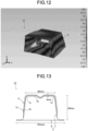
FIG. 13 is a view illustrating a structure of a test specimen used as an invention example in the example. -
FIG. 14 is a view illustrating a structure of a test specimen used as a comparative example in the example. Description of Embodiments - An automotive crashworthiness energy absorption part according to the present embodiment will be described below. Note that, in the present specification and the drawings, elements having substantially the same function and configuration are denoted by the same reference numerals, and redundant description is omitted.
- An automotive crashworthiness energy absorption part 1 (
FIG. 1 ) according to the present embodiment is provided in a front portion or a rear portion of an automotive body, and is axially crushed when a crashworthiness load is input from a front side or a rear side of the automotive body to absorb crashworthiness energy. In a state where the automotive crashworthinessenergy absorption part 1 is attached to the automotive body, a coating layer of electrodeposition paint is formed on a surface thereof, and the coating layer is cured by paint baking treatment to form a coating film. As illustrated inFIG. 1 , acoating part 5 is provided on an outer surface side of atubular member 3 formed using a hat-shaped section part, and acoating film 13 of an electrodeposition paint is formed in a gap between the hat-shaped section part and thecoating part 5.FIG. 2 illustrates a state of the automotive crashworthinessenergy absorption part 1 before electrodeposition coating (hereinafter, referred to as a pre-coated part 2). Each member will be described below with reference toFIGS. 1 and 2 . - The
tubular member 3 is formed of a metal sheet such as a steel sheet, and is formed in a tubular shape by joining anouter part 7 having a hat-shaped cross section shape (hat-shaped section part in the present invention) including atop portion 7a, side-wall portions 7b, andcorner portions 7c that connect thetop portion 7a and the side-wall portions 7b with aninner part 9 having a flat sheet shape at joiningportions 10 that are flange portions of theouter part 7. In a course of a crashworthiness load being input to a tip end of the automotive crashworthinessenergy absorption part 1 in the axial direction and thetubular member 3 being axially crushed when the crashworthiness load exceeds the buckling strength, the automotive crashworthinessenergy absorption part 1 including such atubular member 3 absorbs crashworthiness energy by repeatedly causing buckling deformation in a bellows shape in thetubular member 3. - The
coating part 5 is formed of a metal sheet such as a steel sheet, disposed on an outer surface side of theouter part 7 at a portion including thecorner portions 7c so as to form agap 11 of 0.2 mm or more and 3 mm or less, and is joined by spot welding or the like at joining portions 12 (seeFIG. 2 ). Thecoating part 5 may be provided over the entire length of theouter part 7 in the axial direction, but may be provided only over a range in which the automotive crashworthinessenergy absorption part 1 is desired to be deformed in a bellows shape. For example, in a case where the automotive crashworthinessenergy absorption part 1 is installed on the front portion of an automotive body and desired to be deformed in a bellows shape in a range from the front end to a middle portion in the axial direction, thecoating part 5 is sufficient to be provided in this range of theouter part 7. In addition, a portion of theouter part 7 where thecoating part 5 is not provided, for example, a range from the middle portion to the rear end in the axial direction is sufficient to be formed, for example, in a bead-shape extending in the axial direction, or to have a large sheet thickness so as to increase the deformation strength. - The
coating film 13 of an electrodeposition paint is formed in thegap 11 during electrodeposition coating, which is a general coating process in automobile manufacturing (seeFIG. 1 ). As examples of the type of electrodeposition paint, a polyurethane cationic electrodeposition paint, an epoxy cationic electrodeposition paint, a urethane cationic electrodeposition paint, an acrylic anionic electrodeposition paint, a fluororesin electrodeposition paint, and the like are named, for example. The electrodeposition coating will be specifically described in a second embodiment described later. - Normally, when electrodeposition coating is performed, a coating film of about 0.05 mm is formed on the surface of a steel sheet. However, in the present embodiment, the
coating part 5 is provided on the outer surface side of theouter part 7 in thepre-coated part 2 and hence, the electrodeposition paint enters thegap 11 to form a coating layer, and the coating layer is subjected to heat treatment, whereby thecoating film 13 having a thickness of 0.2 mm or more and 3 mm or less as illustrated inFIG. 1 can be formed. The reason why the crashworthiness energy absorbing effect of the automotive crashworthinessenergy absorption part 1 is improved by forming such acoating film 13 will be described below. - In a course of a crashworthiness load being input to a tip end of the automotive crashworthiness energy absorption part in the axial direction and the tubular member exceeding buckling strength and being axially crushed, the automotive crashworthiness energy absorption part including the tubular member formed of a metal sheet such as a steel sheet absorbs crashworthiness energy by repeatedly causing buckling deformation in a bellows shape in the tubular member.
- However, a bellows-shaped bent portion has a small curvature radius unique to a metal sheet, so that stress is concentrated on the outer surface of the bent portion and fracture is likely to occur. If fracture occurs in the bent portion in the course of axial crushing, the crashworthiness energy absorbing effect is significantly reduced. Therefore, in order to improve the crashworthiness energy absorbing effect, it has been necessary to prevent the fracture occurring in the tubular member that buckles and deforms in a bellows shape.
- In particular, in recent years, high-strength steel sheets adopted for automotive parts for the purpose of achieving both crashworthiness characteristics and weight reduction of automotive bodies have a small elongation as compared with conventional strength steel sheets. The relationship between the steel sheet tensile strength level and the critical curvature radius R for fracture/sheet thickness t of the steel sheet illustrated in Table 1 and
FIG. 3 (see the following Reference 1) indicates that, in a case of the same sheet thickness, the higher the tensile strength TS of the steel sheet, the more likely fracture occurs even if the curvature radius is large. That is, when the automotive crashworthiness energy absorption part using a high-strength steel sheet buckles and deforms in a bellows shape, fracture is likely to occur in a bent tip end in the bellows shape with an increase in steel sheet strength. This has been also a factor that hinders further development of enhancing strength of steel sheets used for automotive crashworthiness energy absorption parts for weight reduction of automotive bodies of automobiles. (Reference 1) Hasegawa Kohei, Kaneko Shinjiro, Seto Kazuhiro, "Cold-rolled and Galvannealed (GA) High Strength Steel Sheets for Automotive Cabin Structure", JFE Technical Report, No. 30 (August 2012), p. 6-12.Table 1 Steel sheet strength level TS [MPa] R/t [-] 780 MPa-class 810 Less than 1.0 980 MPa-class 1020 1.0 1180 MPa-class 1210 1.5 1320 MPa-class 1330 2.0 1470 MPa-class 1510 2.5 - On the other hand, in the present invention, when the
tubular member 3 buckles and deforms in a bellows shape at the time of collision, an object is interposed and sandwiched between a metal sheet and a metal sheet at a bending portion deformed in a concave shape and compressed, thereby increasing the curvature radius of the bending portion deformed in the concave shape, so that fracture of the bent tip end of the bellows shape is prevented. Here, the object interposed between the metal sheet and the metal sheet is preferably an object as lightweight as possible to prevent the weight of the automotive crashworthiness energy absorption part from increasing. Moreover, the object is preferably an object that can be manufactured using a conventional automobile manufacturing line as it is without requiring additional material or process in part manufacturing as in a foam resin or the like in the conventional example. In view of the above, in the present invention, a coating for electrodeposition coating, which is generally performed in automobile manufacturing, is utilized. - In addition, in the
tubular member 3, a region capable of highly absorbing crashworthiness energy is thecorner portion 7c that connects thetop portion 7a and the side-wall portion 7b. However, thecorner portion 7c is also a region that is most likely subjected to machining and where work hardening occurs when theouter part 7 is press formed, and the elongation thereof is further reduced by the work hardening. Therefore, the bent tip end portion of the bellows shape in thecorner portion 7c is a region where fracture is particularly likely to occur. - In view of the above, in the present invention, the
coating part 5 is provided on the outer surface side of theouter part 7 including thecorner portions 7c such that thegap 11 of 0.2 mm to 3 mm is formed between thecoating part 5 and the outer surface. Therefore, the electrodeposition paint enters thegap 11 during electrodeposition coating, and a coating layer having a predetermined thickness can be formed. The coating layer is cured in a baking process of electrodeposition coating, is fixed in thegap 11, and becomes thecoating film 13. The automotive crashworthinessenergy absorption part 1 according to the present embodiment can suppress, when thetubular member 3 has buckled and deformed at the time of collision, occurrence of fracture of the bent tip end portion of a bellows shape by interposing thecoating film 13 inside the concave-shaped bending portion of the bellows shape to increase the curvature radius of the concave-shaped bending portion. Therefore, the crashworthiness energy absorbing effect is improved. Note that the appropriate thickness of thecoating film 13 being from 0.2 mm to 3 mm will be described in examples described later. - The
coating film 13 in the automotive crashworthinessenergy absorption part 1 according to the present embodiment also functions as a vibration-damping material that absorbs vibration. For example, in a case where the automotive crashworthinessenergy absorption part 1 is used as a front side member, which is a part that absorbs crashworthiness energy by axial crushing, thecoating film 13 absorbs vibration of an automotive engine mounted on the front side member, thereby improving vibration-damping properties. The advantageous effects of improving the vibration-damping properties will also be described in the examples described later. - As described above, the
coating part 5 is intended to form thecoating film 13 having a predetermined thickness during electrodeposition coating and does not require strength. Therefore, thecoating part 5 may have a lower strength and a thinner sheet thickness as compared with theouter part 7 and theinner part 9. Furthermore, if the strength of thecoating part 5 is too high, smooth buckling deformation in a bellows shape of thetubular member 3 at the time of collision is hindered. Therefore, the strength is preferably 440 MPa-class or less, for example. - In the present embodiment, a method for manufacturing the automotive crashworthiness
energy absorption part 1 described in the first embodiment will be described. The method for manufacturing the automotive crashworthinessenergy absorption part 1 according to the present embodiment includes a part manufacturing process of manufacturing thepre-coated part 2 in which thecoating part 5 is provided on thetubular member 3, and a coating process of forming a coating layer on thepre-coated part 2 after thepre-coated part 2 is attached to an automotive body and forming thecoating film 13 by thermosetting the coating layer by baking treatment. Each process will be specifically described below with reference toFIG. 4 , which is cross-sectional views of the automotive crashworthinessenergy absorption part 1 illustrated inFIGS. 1 and 2 . - The part manufacturing process is a process of manufacturing the
pre-coated part 2 in which thecoating part 5 is provided on the outer surface side of thetubular member 3 formed by joining theouter part 7 and theinner part 9. As illustrated in an example inFIG. 4(a) , thecoating part 5 is installed on the outer side of theouter part 7 in a range including thecorner portions 7c with thegap 11 of 0.2 mm to 3 mm between thecoating part 5 and the outer surface of theouter part 7, and is joined to the outer surfaces of the side-wall portions 7b by spot welding or the like. In addition, thecoating part 5 may be brought into contact with thetop portion 7a of theouter part 7 to be further joined (seeFIGS. 6(b) and7(b) ). Either the joining of theouter part 7 and theinner part 9 or the joining of theouter part 7 and thecoating part 5 may be performed first. - The coating process is a process of forming the
coating film 13 in thegap 11. In a state of being attached to an automotive body, thepre-coated part 2 manufactured in the part manufacturing process described above is subjected to electrodeposition coating, which is generally performed in the course of automobile manufacturing, whereby thecoating film 13 is formed in thegap 11. Hereinafter, the process will be described while outlining electrodeposition coating and other coating processes in automobile manufacturing. - In general, in order to improve weatherability, design, anticorrosion properties, and the like, a steel sheet of an automotive body of an automobile is sequentially subjected to electrodeposition coating, intermediate coat coating, top coat base coating, and top coat clear coating. In particular, the electrodeposition coating, which the steel sheet is first subjected to, is an important process to improve rust prevention of the automotive body, and has been widely used. In the electrodeposition coating, a treatment for forming a coating layer on the steel sheet by electrodeposition and a treatment for curing the coating layer using a drying furnace (oven) or the like are performed. Hereinafter, an example of the electrodeposition coating will be described, and the correspondence with the coating process in the present embodiment will be given.
- In general electrodeposition coating, first, as a pretreatment, a surface treatment such as degreasing, washing, or a chemical conversion treatment is performed on an automotive part formed by press-forming or the like of a steel sheet. Thereafter, the automotive part on which the surface treatment has been performed is immersed into an electrodeposition tank containing an electrodeposition paint to electrically conduct an object to be coated (automotive part) as a cathode and the electrodeposition paint as an anode. Accordingly, a coating layer of the electrodeposition paint is formed on the surface of the steel sheet (cationic electrodeposition coating). The automotive part in which the coating layer of the electrodeposition paint is formed on the surface by electrical conduction in the electrodeposition tank is subjected to the subsequent treatment such as washing and conveyed to a high-temperature drying furnace (oven), and the coating layer is cured by baking treatment.
- Similarly, when the pre-coated part 2 (see
FIG. 4(a) ) manufactured in the part manufacturing process in the present embodiment is immersed in the electrodeposition tank described above in a state of being attached to the automotive body frame, the electrodeposition paint enters thegap 11, and a coating layer is formed by the subsequent electrical conduction. The coating layer of the electrodeposition paint is formed also on the surface of the steel sheet in a region other than thegap 11, but the thickness thereof is as thin as about 0.05 mm, and thus illustration is omitted. - The automotive crashworthiness
energy absorption part 1 on which the coating layer is formed is then subjected to the baking treatment described above and the coating layer is cured, and thecoating film 13 having a predetermined thickness is fixed in the gap 11 (FIG. 4(b) ). Note that thecoating film 13 is preferably formed in a solid state over the entire region in thegap 11, but a case is conceivable where thecoating film 13 is formed in a state in which a void exists in a portion of thegap 11. Even in such a case, the advantageous effects of the present invention can be achieved as compared with a case where there is nocoating film 13. Therefore, a case where a void exists in a portion of thegap 11 is not excluded. - The electrodeposition coating has high deposition properties to an object to be coated (properties of spreading coating to an uncoated portion). Therefore, the electrodeposition coating is particularly effective for inner sheet members having many irregularities (such as an automotive body frame portion and an engine room). There are various types of electrodeposition paints, and the electrodeposition paints are selectively used according to a coating target and requested functions (deposition properties, energy saving, anticorrosion properties, and the like). It is assumed that electrodeposition coating with a flexible coating film mainly used for an inner sheet (interior) is applied for the automotive crashworthiness
energy absorption part 1 of the present invention, and as examples of the type, a polyurethane cationic electrodeposition paint, an epoxy cationic electrodeposition paint, a urethane cationic electrodeposition paint, an acrylic anionic electrodeposition paint, a fluororesin electrodeposition paint, and the like can be named, for example. - The automotive part subjected to the electrodeposition coating is subjected to intermediate coat coating, top coat base coating, and top coat clear coating. These coatings are mainly performed using a method, referred to as electrostatic painting, of spraying charged coating onto an object to be coated using spray and the like. The intermediate coat coating has functions of roughness masking and light transmittance restraining for an electrodeposition coating surface, and the top coat base coating and the top coat clear coating have functions of design such as coloring, durability, and the like. As examples of coating used for the intermediate coat coating, the top coat base coating, and the top coat clear coating, a polyester-melamine paint, an acrylic-melamine paint, an acrylic-polyester-melamine paint, an alkyd-polyester-melamine paint, and the like are named.
- As described above, according to the method for manufacturing the automotive crashworthiness
energy absorption part 1 described in the present embodiment, thecoating part 5 is provided on thetubular member 3. Therefore, thecoating film 13 of an electrodeposition paint is formed in thegap 11 between thetubular member 3 and thecoating part 5 during electrodeposition coating, which is generally performed in the coating process in automobile manufacturing. Accordingly, it is possible to manufacture the automotive crashworthinessenergy absorption part 1 having high crashworthiness energy absorbing effect without significantly increasing the production cost. - In the first and second embodiments, as illustrated in the cross-sectional views in
FIG. 4 , an example has been described in which the joiningportions 12 of thecoating part 5 are provided on the side-wall portions 7b of theouter part 7, and thecoating film 13 is formed over the outer surfaces of thetop portion 7a, thecorner portions 7c, and portions of the side-wall portions 7b. However, the present invention is not limited thereto. For example, as illustrated inFIG. 5 , the coating film may be formed mainly on the outer surfaces of thetop portion 7a and thecorner portions 7c and only slightly on outer surfaces of the side-wall portions 7b. In addition, as described above, if the coating film is formed on the outer surfaces of thecorner portions 7c where fracture is particularly likely to occur at the time of collision, the crashworthiness energy absorbing effect can be expected to be improved. Therefore, as illustrated inFIG. 6 , thecoating film 13 may be formed mainly on the outer surfaces of thecorner portions 7c. In this process, twocoating parts 5 may be used and joiningportions 12 may each be provided on thetop portion 7a and the side-wall portion 7b (FIG. 6(a) ), or onecoating part 5 may be used and brought into contact with the center of thetop portion 7a to be further joined, and the joiningportions 12 may be provided on the side-wall portions 7b (FIG. 6(b) ). - In addition, as illustrated in
FIG. 7 , thecoating film 13 may be formed on the outer surfaces of the side-wall portions 7b and thecorner portions 7c. Similarly toFIG. 6 , twocoating parts 5 may be used and the joiningportions 12 may each be provided on thetop portion 7a and the side-wall portion 7b (FIG. 7(a) ), or onecoating part 5 may be used and brought into contact with the center of thetop portion 7a to be further joined, and the joiningportions 12 may be provided on the side-wall portions 7b (FIG. 7(b) ). Moreover, as illustrated inFIG. 8 , thecoating part 5 of a hat-shaped cross section type may be fitted on theouter part 7 and theinner part 9, and joined at the joiningportions 10. - In the present embodiment, the
tubular member 3 including theouter part 7 having a hat-shaped cross section shape and theinner part 9 having a flat sheet shape is used as an example, but the present invention is not limited thereto. As illustrated in examples inFIG. 9 , the present embodiment is also applicable to a tubular member formed by making hat-shaped section parts face each other and combining the flange portions.FIG. 9(a) is an example in which thecoating part 5 of the aspect illustrated inFIG. 5 is provided on each of the hat-shaped section parts facing each other. Similarly,FIG. 9(b) is an example in which thecoating part 5 of the aspect illustrated inFIG. 6(a) is provided,FIG. 9(c) is an example in which thecoating part 5 of the aspect illustrated inFIG. 7(b) is provided, andFIG. 9(d) is an example in which thecoating part 5 of the aspect illustrated inFIG. 8 is provided. Note that inFIG. 9 , theouter parts 7 are denoted by the same reference numerals as those inFIG. 4 to FIG. 8 , and theinner parts 9 are denoted by the reference numerals corresponding to theouter parts 7. In addition,FIG. 9 illustrates examples in which theouter part 7 and theinner part 9 are hat-shaped section parts having the same shape, but theinner part 9 may also be a hat-shaped section part having a shape different from that of theouter part 7. - Experiments were performed to confirm the advantageous effects of the automotive crashworthiness
energy absorption part 1 according to the present invention, and the results thereof will be described below. - In the present example, the automotive crashworthiness energy absorption part according to the present invention was used as a test specimen, and evaluation of crashworthiness energy absorption characteristics by an axial crushing test and evaluation of damping characteristics by measuring a frequency response function and calculating a character frequency in an impact vibration test were performed.
- In the axial crushing test, as illustrated in
FIG. 10 , a load was input to atest specimen 21 including thetubular member 3 in the axial direction at a test speed of 17.8 m/s, then a load-stroke curve indicating a relationship between a load and a stroke (amount of axial crush deformation) was measured when thetest specimen 21 underwent an axial crush deformation of 80 mm from a test specimen length (an axial length L0 of the test specimen 21) of 200 mm to 120 mm. Furthermore, taking images with a high-speed camera was performed to observe the state of deformation and the presence or absence of the occurrence of fracture in thetubular member 3. Moreover, absorbed energy at a stroke of from 0 to 80 mm was obtained from the measured load-stroke curve. - On the other hand, in the impact vibration test, as illustrated in
FIG. 11 , an acceleration sensor (manufactured by Ono Sokki Co., Ltd.: NP-3211) was attached to the hangingtest specimen 21 near an edge on the inner side of thetop portion 7a of theouter part 7. Then, impact vibration was applied to the inner side of the side-wall portion 7b of theouter part 7 of thetest specimen 21 with an impact hammer (manufactured by Ono Sokki Co., Ltd.: GK-3100), an impact force and acceleration generated in thetest specimen 21 were taken into an FFT analyzer (manufactured by Ono Sokki Co., Ltd.: CF-7200A), and a frequency response function was calculated. Here, the frequency response function was calculated by averaging processing and curve fitting of five strokes. Then, vibration mode analysis was performed by using the calculated frequency response function, and a character frequency in the same mode was obtained.FIG. 12 illustrates a target vibration mode. -
FIG. 13 illustrates the structure and the shape of thetest specimen 21 that is the automotive crashworthiness energy absorption part 1(FIG. 1 andFIG. 4 (b) ) in which thecoating film 13 according to the first and second embodiments described above is formed. Thetest specimen 21 includes thetubular member 3 in which theouter part 7 and theinner part 9 are joined by spot welding, and thecoating part 5 is joined to the outer surfaces of the side-wall portions 7b of theouter part 7. Thecoating film 13 is formed between theouter part 7 and thecoating part 5. -
FIG. 13 illustrates an example in which thegap 11 that is formed from thetop portion 7a, thecorner portions 7c, and to the side-wall portions 7b, and between them and thecoating part 5 is 3 mm. However, in the present example,test specimens 21 having thegap 11 of 2 mm, 1 mm, and 0.2 mm were also prepared, and the test was performed while changing the thickness of thecoating film 13 formed in thegap 11. - Moreover, as comparative examples, as illustrated in
FIG. 14 ,test specimens 31 including thetubular member 3 and thecoating part 5 and in which thecoating film 13 is not formed are prepared, and the axial crushing test and the impact vibration test were performed similarly to invention examples. Table 2 illustrates the structures of thetest specimens 21 that are the invention examples and thetest specimens 31 that are the comparative examples, conditions of the coating films, and weights of the test specimens, furthermore, calculation results of absorbed energy when the axial crushing test was performed, and results of character frequency obtained by the impact vibration test.Table 2 Structure Coating film Weight of test specimen [kg] Presence or absence of fracture in tubular member Absorbed energy [Test speed 17.8 m/s] Vibration characteristics [Character frequency] (1) Outer part (2) Coating part (3) Inner part Gap between (1) and (2) Presence or absence Thickness [mm] [kJ] [kJ/ kg] [Hz] Material [MPa] Sheet thickness [mm] Material [MPa] Sheet thickness [mm] Material [MPa] Sheet thickness [mm] Invention example 1 590 1.2 270 0.5 590 1.2 3 Presence 3 1.28 Absence 11.1 8.7 430 Invention example 2 590 1.2 270 0.5 590 1.2 2 Presence 2 1.21 Absence 9.0 7.4 340 Invention example 3 590 1.2 440 0.5 590 1.2 2 Presence 2 1.21 Absence 9.5 7.9 340 Invention example 4 1180 1.2 270 0.5 590 1.2 1 Presence 1 1.17 Absence 11.2 9.6 310 Invention example 5 1180 1.2 270 0.5 590 1.2 0.2 Presence 0.2 1.10 Absence 10.7 9.7 280 Comparative example 1 590 1.2 270 0.5 590 1.2 3 Absence - 1.08 Absence 6.5 6.0 155 Comparative example 2 590 1.4 270 0.5 590 1.2 2 Absence - 1.19 Absence 7.0 5.9 175 Comparative example 3 980 1.2 270 0.5 590 1.2 1 Absence - 1.08 Presence 8.1 7.5 155 Comparative example 4 1180 1.2 270 0.5 590 1.2 1 Absence - 1.09 Presence 8.5 7.8 155 Comparative example 5 1180 1.2 - - 590 1.2 - Presence 0.05 0.96 Presence 8.7 9.1 155 Comparative example 6 590 1.2 780 0.5 590 1.2 3 Presence 3 1.28 Presence 8.1 6.3 350 - In each of the invention examples 1 to 5, the test specimen 21 (
FIG. 13 ) including thecoating part 5 and thecoating film 13 was used, and the strength (material) of theouter part 7 and thecoating part 5, and the thickness of thecoating film 13 were changed. On the other hand, in the comparative examples 1 to 4, the test specimen 31 (FIG. 14 ) including thecoating part 5 but not formed with thecoating film 13 was used, and the strength (material) and a sheet thickness of theouter part 7, and thegap 11 between theouter part 7 and thecoating part 5 were changed. In the comparative example 5, a coating film was formed without including thecoating part 5. In the comparative example 6, thecoating part 5 and thecoating film 13 were included similarly to thetest specimen 21, but the strength of the material of thecoating part 5 exceeds that of the material of theouter part 7 and theinner part 9. - For the test specimens formed with the
coating film 13, the weight of the test specimen illustrated in Table 2 is the sum of the respective weights of theouter part 7, theinner part 9, thecoating part 5, and thecoating film 13. For the test specimens without the coating film 13 (the comparative examples 1 to 4), the weight of the test specimen is the sum of the respective weights of theouter part 7, theinner part 9, and thecoating part 5. - In the comparative example 1, the weight of the test specimen was 1.08 kg, and the absorbed energy was 6.5 kJ. Moreover, the character frequency was 155 Hz.
- In the comparative example 2, the sheet thickness of the
outer part 7 and the gap between theouter part 7 and thecoating part 5 were changed from those in the comparative example 1, and the weight of the test specimen was 1.19 kg, and the absorbed energy was 7.0 kJ, which was increased as compared with the comparative example 1. The character frequency was 175 Hz. - In the comparative example 3, a high-strength steel sheet of 980 MPa-class was used for the
outer part 7, and the weight of the test specimen was 1.08 kg. The absorbed energy was 8.1 kJ, which was further increased as compared with the comparative example 2, but fracture occurred in thetubular member 3. The character frequency was 155 Hz. - In the comparative example 4, a high-strength steel sheet of 1180 MPa-class was used for the
outer part 7, and the weight of the test specimen was 1.09 kg. The absorbed energy was 8.5 kJ, which was further increased as compared with the comparative example 3, but fracture occurred in thetubular member 3. The character frequency was 155 Hz. - In the comparative example 5, a high-strength steel sheet of 1180 MPa-class was used for the
outer part 7, and a coating film was formed without installing thecoating part 5, and the thickness of thecoating film 13 was 0.05 mm. The weight of the test specimen was 0.96 kg, and the absorbed energy was 8.7 kJ, which was increased as compared with the comparative example 4, but fracture occurred in thetubular member 3. The character frequency was 155 Hz. - In the comparative example 6, the strength of the material of the
coating part 5 exceeds that of the material of theouter part 7 and the inner part 9 (tubular member 3), and thecoating film 13 having a thickness of 3 mm was further formed. The weight of the test specimen was 1.28 kg, and the absorbed energy was 8.1 kJ, which was increased as compared with the comparative example 1, but fracture occurred in thetubular member 3. The character frequency was 350 Hz. - In the invention example 1, the
test specimen 21 in which a steel sheet having a steel sheet strength of 590 MPa-class was used for theouter part 7, and the thickness of thecoating film 13 was 3 mm was used. The absorbed energy in the invention example 1 was 11.1 kJ. The absorbed energy was significantly improved as compared with the absorbed energy (= 6.5 kJ) in the comparative example 1 using the same material but not formed with thecoating film 13, and fracture did not occur in thetubular member 3. In addition, the absorbed energy was significantly improved even as compared with the comparative example 3 (= 8.1 kJ) in which the high-strength steel sheet of 980 MPa-class was used for theouter part 7 and the comparative example 4 (= 8.5 kJ) in which the high-strength steel sheet of 1180 MPa-class was used for theouter part 7. The weight of the test specimen (= 1.28 kg) in the invention example 1 was increased as compared with the comparative example 1 (= 1.08 kg), the comparative example 3 (= 1.08 kg), and the comparative example 4 (= 1.09 kg), but the absorbed energy per unit weight obtained by dividing the absorbed energy by the weight of the test specimen was 8.7 kJ/kg, which was improved as compared with the comparative example 1 (= 6.0 kJ/kg), the comparative example 3 (= 7.5 kJ/kg), and the comparative example 4 (= 7.8 kJ/kg). In addition, the character frequency in the invention example 1 was 430 Hz, which was significantly increased as compared with the comparative example 1, the comparative example 3, and the comparative example 4 (= 155 Hz). - In the invention example 2, the same material as in the invention example 1 was used, and the thickness of the
coating film 13 was set to 2 mm. The weight of the test specimen was 1.21 kg, which was lighter in weight than that in the invention example 1 (= 1.28 kg). The absorbed energy in the invention example 2 was 9.0 kJ, which was improved as compared with the absorbed energy (= 7.0 kJ) in the comparative example 2 having the same shape and in which the sheet thickness of theouter part 7 is large. Fracture did not occur in thetubular member 3. Moreover, the absorbed energy per unit weight in the invention example 2 was 7.4 kJ/kg, which was improved as compared with the comparative example 2 (= 5.9 kJ/kg). In addition, the character frequency in the invention example 2 was 340 Hz, which was significantly increased as compared with the comparative example 2 (= 175 Hz). - In the invention example 3, the thickness of the
coating film 13 was set to 2 mm similarly to the invention example 2, and the steel sheet strength of thecoating part 5 was set to 440 MPa-class. In the comparative example 6 in which the steel sheet strength of thecoating part 5 was 780 MPa exceeding the steel sheet strength of theouter part 7, fracture occurred in thetubular member 3, but fracture did not occur in the invention example 3. In addition, the absorbed energy in the invention example 3 was 9.5 kJ, which was improved as compared with the comparative example 6 (= 8.1 kJ). - In the invention example 4, a high-strength steel sheet having a steel sheet strength of 1180 MPa-class was used for the
outer part 7, and the thickness of thecoating film 13 was set to 1 mm. The absorbed energy in the invention example 4 was 11.2 kJ, and fracture did not occur in thetubular member 3. The absorbed energy was significantly improved as compared with the comparative example 4 (= 8.5 kJ) in which a steel sheet of the same material was used for theouter part 7 and fracture occurred. In addition, the weight of the test specimen in the invention example 4 was 1.17 kg, which was lighter in weight than that in the invention example 1, furthermore, the absorbed energy per unit weight (= 9.6 kJ/kg) was improved as compared with the invention example 1 (= 8.7 kJ/kg) and the comparative example 4 (= 7.8 kJ/kg). Moreover, the character frequency in the invention example 4 was 310 Hz, which was significantly increased as compared with the comparative example 4 (= 155 Hz). - In the invention example 5, in the same material as that in the invention example 4, the thickness of the
coating film 13 was set to 0.2 mm, which is about the same thickness as a laminate in a normal laminated steel sheet, and the weight of the test specimen was 1.10 kg. The absorbed energy in the invention example 5 was 10.7 kJ, and the absorbed energy per unit weight was 9.7 kJ/kg, which was improved as compared with the comparative example 5 (= 9.1 kJ/kg) in which a coating film of 0.05 mm was formed without including thecoating part 5. In addition, fracture occurred in the tubular member in the comparative example 5, but fracture did not occur in the invention example 5. Moreover, the character frequency in the invention example 5 was 280 Hz, which was increased as compared with the comparative example 5 (= 155 Hz). - Note that, although not illustrated in the table, in a case where the gap between the
outer part 7 and thecoating part 5 was set to 4 mm or more, that is, in a case where thecoating film 13 having a thickness of 4 mm or more was formed, sufficient drying could not be performed in the baking treatment of the electrodeposition coating, and dripping of the coating occurred, and the dried coating film was not formed up to a predetermined gap. Therefore, in the present invention, the appropriate thickness of thecoating film 13 was set to 0.2 mm to 3 mm. - In this manner, it has been shown that the automotive crashworthiness
energy absorption part 1 according to the present invention can efficiently improve the crashworthiness energy absorbing effect while suppressing an increase in weight in a case where a crashworthiness load is input in the axial direction and causes axial crushing, and the character frequency when an impact is applied increases and the vibration-damping properties can be improved. - Note that the reason why the vibration-damping properties are improved with an increase in the character frequency is as follows. When the character frequency of the
tubular member 3, which is a crashworthiness member like the front side member described above, falls within a frequency range of vibration of an engine mounted on the member, sympathetic vibration occurs and the vibration increases. For example, when the engine rotates at 4000 rpm, which is a high rotation range of normal driving, the crankshaft turns at the same rotation speed, and in a four-cycle engine, explosion and vibrates occur once every two rotations. Therefore, the frequency of the vibration is 133 Hz in a four-cylinder engine, 200 Hz in a six-cylinder engine, and 267 Hz in an eight-cylinder engine. Accordingly, with the character frequency of about 280 Hz or more as in the present invention, the sympathetic vibration described above can be reliably prevented, and the vibration-damping properties are improved. - According to the present invention, it is possible to provide: an automotive crashworthiness energy absorption part such as a front side member and a crash box that, when a crashworthiness load is input from the front side or the rear side of an automotive body and causes axial crushing, improves crashworthiness energy absorbing effect by forming a thick coating film of coating on an outer surface, can function as a vibration-damping material that absorbs vibration generated in the automotive body, and can reduce additional production processes, thus preventing a large increase in the production cost; and a method for manufacturing the automotive crashworthiness energy absorption part.
-
- 1
- AUTOMOTIVE CRASHWORTHINESS ENERGY ABSORPTION PART
- 2
- PRE-COATED PART
- 3
- TUBULAR MEMBER
- 5
- COATING PART
- 7
- OUTER PART
- 7a
- TOP PORTION
- 7b
- SIDE-WALL PORTION
- 7c
- CORNER PORTION
- 9
- INNER PART
- 9a
- TOP PORTION
- 9b
- SIDE-WALL PORTION
- 9c
- CORNER PORTION
- 10
- JOINING PORTION (TUBULAR MEMBER)
- 11
- GAP
- 12
- JOINING PORTION (COATING PART)
- 13
- COATING FILM
- 21
- TEST SPECIMEN (INVENTION EXAMPLE)
- 31
- TEST SPECIMEN (COMPARATIVE EXAMPLE)
Claims (2)
- An automotive crashworthiness energy absorption part for being provided in a front portion or a rear portion of an automotive body, the automotive crashworthiness energy absorption part being axially crushed when a crashworthiness load is input from a front side or a rear side of the automotive body to absorb crashworthiness energy, and comprising:a tubular member formed by using a hat-shaped section part including a top portion and a side-wall portion;a coating part made of a material having a lower strength than the tubular member, the coating part being arranged on outer surfaces of the top portion and the side-wall portion at a portion including a corner portion configured to connect the top portion and the side-wall portion, with a gap of 0.2 mm or more and 3 mm or less from the outer surface of the top portion, the outer surface of the side-wall portion, and an outer surface of the corner portion; anda coating film of an electrodeposition paint formed in the gap.
- A method for manufacturing an automotive crashworthiness energy absorption part provided in a front portion or a rear portion of an automotive body, the automotive crashworthiness energy absorption part being axially crushed when a crashworthiness load is input from a front side or a rear side of the automotive body to absorb crashworthiness energy, the method comprising:a part manufacturing step of manufacturing a pre-coated part including: a tubular member formed by using a hat-shaped section part including a top portion and a side-wall portion; and a coating part made of a material having a lower strength than the tubular member, the coating part being arranged on an outer surface of the tubular member at a portion including a corner portion configured to connect the top portion and the side-wall portion, with a gap of 0.2 mm or more and 3 mm or less from an outer surface of the top portion, an outer surface of the side-wall portion, and an outer surface of the corner portion; anda coating step of forming a coating layer on a surface of a part including the gap by an electrodeposition coating process by electrodeposition coating in a state where the pre-coated part is attached to the automotive body, and forming a coating film by thermosetting the coating layer by paint baking treatment subsequent to the electrodeposition coating process.
Applications Claiming Priority (2)
| Application Number | Priority Date | Filing Date | Title |
|---|---|---|---|
| JP2020137778A JP7238867B2 (en) | 2020-08-18 | 2020-08-18 | Automobile collision energy absorbing part, method for manufacturing the automobile collision energy absorbing part |
| PCT/JP2021/017682 WO2022038842A1 (en) | 2020-08-18 | 2021-05-10 | Collision energy absorption component for automobile, and method for manufacturing said collision energy absorption component for automobile |
Publications (2)
| Publication Number | Publication Date |
|---|---|
| EP4201752A1 true EP4201752A1 (en) | 2023-06-28 |
| EP4201752A4 EP4201752A4 (en) | 2024-02-07 |
Family
ID=80322854
Family Applications (1)
| Application Number | Title | Priority Date | Filing Date |
|---|---|---|---|
| EP21857994.4A Pending EP4201752A4 (en) | 2020-08-18 | 2021-05-10 | Collision energy absorption component for automobile, and method for manufacturing said collision energy absorption component for automobile |
Country Status (7)
| Country | Link |
|---|---|
| US (1) | US20230257899A1 (en) |
| EP (1) | EP4201752A4 (en) |
| JP (1) | JP7238867B2 (en) |
| KR (1) | KR20230036150A (en) |
| CN (1) | CN115867466A (en) |
| MX (1) | MX2023001873A (en) |
| WO (1) | WO2022038842A1 (en) |
Families Citing this family (2)
| Publication number | Priority date | Publication date | Assignee | Title |
|---|---|---|---|---|
| JP6950871B2 (en) * | 2019-01-23 | 2021-10-13 | Jfeスチール株式会社 | Body skeleton parts |
| WO2022025098A1 (en) * | 2020-07-31 | 2022-02-03 | 日本製鉄株式会社 | Structural member for automobile body |
Family Cites Families (11)
| Publication number | Priority date | Publication date | Assignee | Title |
|---|---|---|---|---|
| JP3620340B2 (en) | 1999-05-12 | 2005-02-16 | 東海ゴム工業株式会社 | High rigidity foam filling structure |
| JP3928371B2 (en) * | 2001-05-16 | 2007-06-13 | 日産自動車株式会社 | Side sill structure of automobile |
| KR20040104765A (en) * | 2003-06-03 | 2004-12-13 | 현대자동차주식회사 | Side Sill Outer Panel Structure |
| JP4462978B2 (en) | 2004-03-26 | 2010-05-12 | 日産自動車株式会社 | Energy absorption structure of automobile |
| JP2006240134A (en) | 2005-03-04 | 2006-09-14 | Nissan Motor Co Ltd | Structural member for car and its production method |
| JP2008162427A (en) * | 2006-12-28 | 2008-07-17 | Daihatsu Motor Co Ltd | Reinforcement structure for side member |
| KR101637617B1 (en) * | 2008-07-29 | 2016-07-07 | 다우 글로벌 테크놀로지스 엘엘씨 | Toughened expandable epoxy resins for stiffening and energy dissipation in automotive cavities |
| JP6276230B2 (en) | 2015-09-24 | 2018-02-07 | 本田技研工業株式会社 | Method for improving strength and rigidity of automobile body |
| JP6315292B2 (en) * | 2016-02-04 | 2018-04-25 | マツダ株式会社 | Vehicle frame structure |
| JP6631560B2 (en) | 2017-03-02 | 2020-01-15 | Jfeスチール株式会社 | Automotive collision energy absorbing parts |
| JP6729762B1 (en) | 2019-05-28 | 2020-07-22 | Jfeスチール株式会社 | Collision energy absorbing component for automobile and manufacturing method thereof |
-
2020
- 2020-08-18 JP JP2020137778A patent/JP7238867B2/en active Active
-
2021
- 2021-05-10 KR KR1020237005056A patent/KR20230036150A/en unknown
- 2021-05-10 WO PCT/JP2021/017682 patent/WO2022038842A1/en unknown
- 2021-05-10 MX MX2023001873A patent/MX2023001873A/en unknown
- 2021-05-10 CN CN202180046335.5A patent/CN115867466A/en active Pending
- 2021-05-10 US US18/012,719 patent/US20230257899A1/en active Pending
- 2021-05-10 EP EP21857994.4A patent/EP4201752A4/en active Pending
Also Published As
| Publication number | Publication date |
|---|---|
| CN115867466A (en) | 2023-03-28 |
| EP4201752A4 (en) | 2024-02-07 |
| US20230257899A1 (en) | 2023-08-17 |
| KR20230036150A (en) | 2023-03-14 |
| MX2023001873A (en) | 2023-03-10 |
| WO2022038842A1 (en) | 2022-02-24 |
| JP7238867B2 (en) | 2023-03-14 |
| JP2022034129A (en) | 2022-03-03 |
Similar Documents
| Publication | Publication Date | Title |
|---|---|---|
| KR102519996B1 (en) | Automotive crashworthiness energy absorptive part and method for manufacturing same | |
| EP4201752A1 (en) | Collision energy absorption component for automobile, and method for manufacturing said collision energy absorption component for automobile | |
| KR102602085B1 (en) | Automotive crashworthiness energy absorption part and method for manufacturing the same | |
| WO2021009974A1 (en) | Collision energy absorption component for automobile, and method for manufacturing said collision energy absorption component for automobile | |
| US20100196736A1 (en) | Vibration-damping composite component | |
| EP4227167A1 (en) | Manufacturing method for automotive body including automotive crash energy absorption component | |
| JP6693605B1 (en) | Vehicle structural member | |
| JP7140094B2 (en) | Method for manufacturing vehicle body having collision energy absorbing parts for automobile | |
| JP7078146B1 (en) | A method for manufacturing a collision energy absorbing component for an automobile and a collision energy absorbing component for an automobile. | |
| WO2021048958A1 (en) | Center pillar inner and center pillar |
Legal Events
| Date | Code | Title | Description |
|---|---|---|---|
| STAA | Information on the status of an ep patent application or granted ep patent |
Free format text: STATUS: THE INTERNATIONAL PUBLICATION HAS BEEN MADE |
|
| PUAI | Public reference made under article 153(3) epc to a published international application that has entered the european phase |
Free format text: ORIGINAL CODE: 0009012 |
|
| STAA | Information on the status of an ep patent application or granted ep patent |
Free format text: STATUS: REQUEST FOR EXAMINATION WAS MADE |
|
| 17P | Request for examination filed |
Effective date: 20230214 |
|
| AK | Designated contracting states |
Kind code of ref document: A1 Designated state(s): AL AT BE BG CH CY CZ DE DK EE ES FI FR GB GR HR HU IE IS IT LI LT LU LV MC MK MT NL NO PL PT RO RS SE SI SK SM TR |
|
| DAV | Request for validation of the european patent (deleted) | ||
| DAX | Request for extension of the european patent (deleted) | ||
| A4 | Supplementary search report drawn up and despatched |
Effective date: 20240108 |
|
| RIC1 | Information provided on ipc code assigned before grant |
Ipc: B62D 21/15 20060101ALI20240102BHEP Ipc: B60R 19/34 20060101AFI20240102BHEP |