WO2022025098A1 - Structural member for automobile body - Google Patents
Structural member for automobile body Download PDFInfo
- Publication number
- WO2022025098A1 WO2022025098A1 PCT/JP2021/027843 JP2021027843W WO2022025098A1 WO 2022025098 A1 WO2022025098 A1 WO 2022025098A1 JP 2021027843 W JP2021027843 W JP 2021027843W WO 2022025098 A1 WO2022025098 A1 WO 2022025098A1
- Authority
- WO
- WIPO (PCT)
- Prior art keywords
- bead
- top plate
- structural member
- side wall
- longitudinal direction
- Prior art date
Links
- 239000011324 bead Substances 0.000 claims abstract description 202
- 238000005304 joining Methods 0.000 claims abstract description 40
- 229910000831 Steel Inorganic materials 0.000 claims description 25
- 239000010959 steel Substances 0.000 claims description 25
- 238000000926 separation method Methods 0.000 claims description 19
- 238000013001 point bending Methods 0.000 description 37
- 238000005452 bending Methods 0.000 description 27
- 230000007423 decrease Effects 0.000 description 13
- 230000001965 increasing effect Effects 0.000 description 13
- 238000004088 simulation Methods 0.000 description 12
- 239000000463 material Substances 0.000 description 10
- 230000004048 modification Effects 0.000 description 9
- 238000012986 modification Methods 0.000 description 9
- 230000000694 effects Effects 0.000 description 7
- 238000010586 diagram Methods 0.000 description 5
- 238000012360 testing method Methods 0.000 description 5
- 239000004918 carbon fiber reinforced polymer Substances 0.000 description 4
- 239000013585 weight reducing agent Substances 0.000 description 4
- 238000003466 welding Methods 0.000 description 4
- 229910052751 metal Inorganic materials 0.000 description 3
- 239000002184 metal Substances 0.000 description 3
- 229910000838 Al alloy Inorganic materials 0.000 description 2
- RTAQQCXQSZGOHL-UHFFFAOYSA-N Titanium Chemical compound [Ti] RTAQQCXQSZGOHL-UHFFFAOYSA-N 0.000 description 2
- 229910052782 aluminium Inorganic materials 0.000 description 2
- XAGFODPZIPBFFR-UHFFFAOYSA-N aluminium Chemical compound [Al] XAGFODPZIPBFFR-UHFFFAOYSA-N 0.000 description 2
- 230000006866 deterioration Effects 0.000 description 2
- 238000011156 evaluation Methods 0.000 description 2
- 238000000034 method Methods 0.000 description 2
- 238000000465 moulding Methods 0.000 description 2
- 230000002093 peripheral effect Effects 0.000 description 2
- 238000003825 pressing Methods 0.000 description 2
- 238000012545 processing Methods 0.000 description 2
- 239000011347 resin Substances 0.000 description 2
- 229920005989 resin Polymers 0.000 description 2
- 239000010936 titanium Substances 0.000 description 2
- 229910052719 titanium Inorganic materials 0.000 description 2
- 239000006096 absorbing agent Substances 0.000 description 1
- 229910001566 austenite Inorganic materials 0.000 description 1
- 230000004888 barrier function Effects 0.000 description 1
- 238000005219 brazing Methods 0.000 description 1
- 230000008859 change Effects 0.000 description 1
- 230000003111 delayed effect Effects 0.000 description 1
- 230000002708 enhancing effect Effects 0.000 description 1
- 230000001747 exhibiting effect Effects 0.000 description 1
- 230000008569 process Effects 0.000 description 1
- 238000010791 quenching Methods 0.000 description 1
- 230000000171 quenching effect Effects 0.000 description 1
- 230000009467 reduction Effects 0.000 description 1
- 239000012779 reinforcing material Substances 0.000 description 1
- 230000003313 weakening effect Effects 0.000 description 1
Images


Classifications
-
- B—PERFORMING OPERATIONS; TRANSPORTING
- B60—VEHICLES IN GENERAL
- B60R—VEHICLES, VEHICLE FITTINGS, OR VEHICLE PARTS, NOT OTHERWISE PROVIDED FOR
- B60R19/00—Wheel guards; Radiator guards, e.g. grilles; Obstruction removers; Fittings damping bouncing force in collisions
- B60R19/02—Bumpers, i.e. impact receiving or absorbing members for protecting vehicles or fending off blows from other vehicles or objects
- B60R19/18—Bumpers, i.e. impact receiving or absorbing members for protecting vehicles or fending off blows from other vehicles or objects characterised by the cross-section; Means within the bumper to absorb impact
-
- B—PERFORMING OPERATIONS; TRANSPORTING
- B62—LAND VEHICLES FOR TRAVELLING OTHERWISE THAN ON RAILS
- B62D—MOTOR VEHICLES; TRAILERS
- B62D21/00—Understructures, i.e. chassis frame on which a vehicle body may be mounted
- B62D21/15—Understructures, i.e. chassis frame on which a vehicle body may be mounted having impact absorbing means, e.g. a frame designed to permanently or temporarily change shape or dimension upon impact with another body
-
- B—PERFORMING OPERATIONS; TRANSPORTING
- B62—LAND VEHICLES FOR TRAVELLING OTHERWISE THAN ON RAILS
- B62D—MOTOR VEHICLES; TRAILERS
- B62D25/00—Superstructure or monocoque structure sub-units; Parts or details thereof not otherwise provided for
- B62D25/02—Side panels
- B62D25/025—Side sills thereof
-
- B—PERFORMING OPERATIONS; TRANSPORTING
- B62—LAND VEHICLES FOR TRAVELLING OTHERWISE THAN ON RAILS
- B62D—MOTOR VEHICLES; TRAILERS
- B62D25/00—Superstructure or monocoque structure sub-units; Parts or details thereof not otherwise provided for
- B62D25/04—Door pillars ; windshield pillars
-
- B—PERFORMING OPERATIONS; TRANSPORTING
- B60—VEHICLES IN GENERAL
- B60R—VEHICLES, VEHICLE FITTINGS, OR VEHICLE PARTS, NOT OTHERWISE PROVIDED FOR
- B60R19/00—Wheel guards; Radiator guards, e.g. grilles; Obstruction removers; Fittings damping bouncing force in collisions
- B60R19/02—Bumpers, i.e. impact receiving or absorbing members for protecting vehicles or fending off blows from other vehicles or objects
- B60R19/18—Bumpers, i.e. impact receiving or absorbing members for protecting vehicles or fending off blows from other vehicles or objects characterised by the cross-section; Means within the bumper to absorb impact
- B60R2019/1806—Structural beams therefor, e.g. shock-absorbing
- B60R2019/1813—Structural beams therefor, e.g. shock-absorbing made of metal
- B60R2019/1826—Structural beams therefor, e.g. shock-absorbing made of metal of high-tension steel
Definitions
- the present invention relates to a structural member of an automobile body.
- the present application claims priority based on Japanese Patent Application No. 2020-130553 filed in Japan on July 31, 2020, the contents of which are incorporated herein by reference.
- Patent Document 1 describes a collision-resistant reinforcing material for vehicles having excellent buckling resistance, which is designed to provide a concave bead so as to extend in the center of the width direction of the main body along the longitudinal direction of the main body. It has been disclosed.
- Patent Document 2 discloses a metal absorber for a vehicle having concave or convex beads substantially parallel to the front-rear direction of the vehicle on one or both of the upper web and the lower web.
- the present invention has been made in view of the above problems, and an object of the present invention is to exhibit excellent collision safety performance by improving the load capacity at the initial stage of the deformation of the deformation in the local buckling mode. Is to provide a structural member capable of.
- the first aspect of the present invention is a top plate portion extending in the longitudinal direction and a pair of side wall portions extending through first corner portions formed at both ends in the width direction of the top plate portion.
- a hat-shaped member having a pair of flange portions extending through a second corner portion formed at an end portion of the pair of side wall portions opposite to the first corner portion, and the hat-shaped member.
- a joining member having a pair of joining portions to be joined to the pair of flange portions and a top plate facing portion facing the top plate portion of the hat-shaped member is provided on the top plate portion.
- a structural member of an automobile body in which a first bead extending along the longitudinal direction is formed, and two or more second beads extending along the direction intersecting the longitudinal direction are formed on the pair of side wall portions. Is.
- two or more of the first beads may be formed in parallel in the width direction.
- the first bead may be formed so that the center of the first bead in the width direction is located in a region up to a point having a separation distance of 1/4 of the width of the first bead.
- in the cross section perpendicular to the longitudinal direction from the boundary point between the top plate portion and the first corner portion to a point having a separation distance of 20 mm.
- the first bead may be formed so that the boundary point between the first bead and the top plate portion is located in the region of. (5)
- the second bead may extend from the first corner portion. (6)
- the second bead may extend to the second corner portion.
- the width of the first bead is 5 mm to 20 mm, and the depth of the first bead is 5 mm to 20 mm. It may be.
- the aspect ratio calculated by the depth / width of the first bead is 0.25 to 4.0. There may be.
- the width of the second bead is 10 mm to 60 mm, and the depth of the second bead is 2 mm to 10 mm. It may be.
- the aspect ratio calculated by the depth / width of the second bead is 0.05 to 1.0. There may be. (11) In the structural member of the automobile body according to any one of (1) to (10) above, even if the top plate portion of the hat-shaped member is formed of a steel plate having a plate thickness of 1.2 mm or less. good. (12) In the structural member of the automobile body according to any one of (1) to (11) above, the top plate portion of the hat-shaped member may be formed of a steel plate having a tensile strength of 980 MPa or more. .. (13) In the structural member of the automobile body according to any one of (1) to (12) above, the hat-shaped member may be a hardened member.
- the deformation resistance to each of the stress in the longitudinal direction and the stress in the height direction generated in the part is increased, and a thin plate thickness material is used.
- high collision safety performance can be obtained.
- FIG. 1 is a schematic diagram for explaining the three-point bending characteristic of the local buckling mode
- (b) is a schematic diagram for explaining the three-point bending characteristic of the wall surface buckling mode
- (c) is a schematic diagram. It is a schematic diagram for demonstrating the moment bending characteristic.
- FIG. 2 is a cross-sectional view taken along the line AA'in FIG.
- It is a schematic plan view of the structural member 100 which concerns on 1st Embodiment.
- It is an enlarged view of the part B of FIG.
- FIG. 10 is a cross-sectional view taken along the line BB'in FIG. It is a perspective view which shows the state after deformation of the structural member 200 which concerns on 2nd Embodiment. It is a schematic diagram for demonstrating the three-point bending condition. It is a graph which shows the result of an Example.
- the bending and crushing characteristics of automobile parts are the three-point bending characteristics when the impact of a collision is directly applied to the crushed part of the part and deformed, and the bending and crushing characteristics when the impact of a collision is indirectly applied to the crushed part of the part and deformed. It is roughly divided into moment bending characteristics. Of these, the three-point bending characteristics are classified into three-point bending characteristics in the local buckling mode and three-point bending characteristics in the wall surface buckling mode. For the 3-point bending characteristics in the local buckling mode and the 3-point bending characteristics in the wall buckling mode, perform a 3-point bending test in which the impactor directly collides with the component as shown in FIGS. 1 (a) and 1 (b).
- the moment bending characteristic is often evaluated by the moment bending characteristic obtained by performing a moment bending test in which the impactor or the like does not come into contact with the crushed portion of the component.
- the present inventor examined the shape of a component for enhancing the collision safety performance against deformation of the local buckling mode as shown in FIG. 1 (a), and obtained the following findings.
- the axial direction of the structural member that is, the direction in which the axis extends is referred to as the longitudinal direction Z.
- the direction parallel to the top plate portion on the plane perpendicular to the longitudinal direction Z is referred to as the width direction X
- the direction perpendicular to the longitudinal direction Z and the width direction X is referred to as the height direction Y.
- the direction away from the axis of the structural member is called the outer direction, and the opposite direction is called the inner direction.
- the structural member 100 (hereinafter referred to as the structural member 100) of the automobile body according to the first embodiment of the present invention will be described.
- the structural member 100 is a member having a closed cross-section structure composed of a hat-shaped member 110 and a joining member 120.
- Examples of the application of the structural member 100 include a B-pillar, a side sill, a bumper line force, and the like.
- the structural member 100 according to the present embodiment is a component assuming that the hat-shaped member 110 faces the outside of the vehicle and the joining member 120 faces the inside of the vehicle.
- FIG. 3 is a cross-sectional view taken along the line AA'of FIG.
- the hat-shaped member 110 includes a top plate portion 111 extending along the longitudinal direction Z and first corner portions 113, 113 formed at both ends of the top plate portion 111 in the width direction X. Through a pair of side wall portions 115, 115 extending through and a second corner portion 117, 117 formed at an end of the pair of side wall portions 115, 115 opposite to the first corner portions 113, 113. It has a pair of extending flange portions 119 and 119.
- the hat-shaped member 110 may be a member made of a resin plate, a CFRP (Carbon Fiber Reinforced Plastic) plate, or a metal plate (aluminum plate, aluminum alloy plate, stainless plate, titanium plate, steel plate, etc.).
- the hat-shaped member 110 can be easily formed by, for example, cold-pressing or warm-pressing the plate material. Further, the hat mold member 110 may be formed by hot stamping, in which the steel sheet is heated to a high temperature in the austenite region and then press-formed by the mold, and at the same time, quenching treatment is performed in the mold. Therefore, the hat-shaped member 110 may be a hardened member.
- the top plate portion 111 corresponds to a portion in direct contact with the impactor in the three-point bending test in the local buckling mode shown in FIG.
- the structural member 100 according to the present embodiment is installed in the automobile in a posture in which the hat-shaped member 110 faces the outside of the vehicle. Therefore, when an impact load from the outside of the vehicle is input to the top plate portion 111 and the structural member 100 is bent and deformed, a compressive stress is generated in the top plate portion 111 along the longitudinal direction Z.
- the top plate portion 111 is preferably formed of a steel plate having a plate thickness of 1.2 mm or less, and more preferably formed of a steel plate having a plate thickness of 1.0 mm or less.
- the lower limit of the plate thickness of the top plate portion 111 is not particularly limited, and may be 0.3 mm or more.
- the top plate portion 111 is preferably formed of a steel plate having a tensile strength of 980 MPa or more, and more preferably formed of a steel plate having a tensile strength of 1470 MPa or more. ..
- the width W of the top plate portion 111 may be 40 mm or more and 200 mm or less. As shown in FIG. 3, the width W of the top plate portion 111 is between the boundary points between the top plate portion 111 and the first corner portions 113, 113 at both ends thereof in a cross section perpendicular to the longitudinal direction Z of the structural member 100. Is the separation distance in the width direction X.
- the first bead 150 formed on the top plate portion 111 will be described later.
- the pair of side wall portions 115, 115 extend through the first corner portions 113, 113 formed at both ends of the top plate portion 111 in the width direction X.
- the first corner portions 113 and 113 have an R portion having a radius of curvature of, for example, 1 mm to 10 mm. Since the structural member 100 according to the present embodiment is installed in the automobile in a posture in which the hat-shaped member 110 faces the outside of the vehicle, an impact load from the outside of the vehicle is input to the top plate portion 111 to bend and deform the structural member 100.
- a compressive stress along the direction intersecting the longitudinal direction Z that is, a compressive stress along the sidewall 115 in the cross section perpendicular to the longitudinal direction Z of the structural member 100 is generated in the pair of side wall portions 115, 115. ..
- the second bead 160 formed on the side wall portion 115 will be described later.
- the plate thickness and tensile strength of the side wall portion 115 may be the same as the tensile strength and plate thickness of the top plate portion 111.
- the height H of the side wall portion 115 may be 20 mm or more and 150 mm or less. As shown in FIG. 3, the height H of the side wall portion 115 is the boundary point between the side wall portion 115 and the first corner portion 113 in the cross section perpendicular to the longitudinal direction Z of the structural member 100, and the side wall portion 115 and the second side wall portion 115. It is a separation distance in the height direction Y from the boundary point with the corner portion 117.
- the second corner portions 117 and 117 have an R portion having a radius of curvature of, for example, 1 mm to 10 mm.
- the second corner portions 117 and 117 are formed at the ends of the pair of side wall portions 115 and 115 opposite to the first corner portions 113 and 113.
- the pair of flange portions 119,119 are formed so as to extend outward from the second corner portions 117,117.
- Spot welds 170 for joining to the joining member 120 are formed on the flange portion 119 at a predetermined pitch in the longitudinal direction Z. Note that spot welding is an example of means for joining, and may be laser welding or brazing.
- the joining member 120 is a member that is joined to the hat-shaped member 110. Since the structural member 100 according to the present embodiment is installed in the automobile in a posture in which the joining member 120 faces the inside of the vehicle, an impact load from the outside of the vehicle is input to the top plate portion 111 and the structural member 100 is bent and deformed. When this occurs, a tensile stress is generated in the joining member 120 along the longitudinal direction Z. Therefore, by joining the joining member 120 to the hat-shaped member 110, it is possible to increase the deformation resistance against the tensile stress along the longitudinal direction Z, so that high collision safety performance can be exhibited.
- the joining member 120 by joining the joining member 120 to the hat-shaped member 110, it is possible to prevent the side wall portion 115 from opening in the width direction X when the structural member 100 is bent and deformed. Therefore, it is possible to prevent deterioration of the three-point bending characteristic and to exhibit high collision safety performance.
- the joining member 120 may be a member made of a resin plate, a CFRP (Carbon Fiber Reinforced Plastic) plate, or a metal plate (aluminum plate, aluminum alloy plate, stainless plate, titanium plate, steel plate, etc.).
- CFRP Carbon Fiber Reinforced Plastic
- the tensile strength and plate thickness of the joining member 120 are not particularly limited. As described above, when the impact load from the outside of the vehicle is input to the top plate portion 111 and the structural member 100 is bent and deformed, a tensile stress is generated in the joint member 120 along the longitudinal direction Z.
- the plate thickness and strength of the member greatly affect the buckling deformation due to the compressive stress, but in the case of tensile stress, the plate thickness and low strength are thin as long as the member is not broken by the tensile deformation.
- the material can be used. Therefore, for example, the tensile strength and the plate thickness of the joining member 120 may be lower than the top plate portion 111 of the hat-shaped member 110, or may be a thin plate thickness. However, the joining member 120 may be a hardened member.
- the joining member 120 has a pair of joining portions 121 and 121 provided at both ends in the width direction X, and a top plate facing portion 123 provided at the center of the width direction X.
- the pair of joint portions 121, 121 is a portion where the pair of flange portions 119, 119 of the hat-shaped member 110 to be joined by spot welding or the like come into surface contact with each other.
- the top plate facing portion 123 is a portion of the joining member 120 excluding the joining portion 121, and is a portion facing the top plate portion 111 of the hat-shaped member 110.
- the top plate facing portion 123 does not have a structure that supports the top plate portion 111 from the inside.
- the top plate facing portion 123 is not in contact with the inner surface of the top plate portion 111. Since the cross-sectional circumference per area surrounded by the closed cross section of the structural member 100 can be reduced, the three-point bending characteristic (for example, maximum load) obtained per member weight can be efficiently improved. That is, weight reduction can be realized.
- the joint member 120 is composed of a single flat plate-shaped steel plate, the joint portion 121 and the top plate facing portion 123 are regions adjacent to each other in the same plane.
- the width of the top plate facing portion 123 may be 40 mm or more and 200 mm or less.
- the width of the top plate facing portion 123 is preferably larger than the width W of the top plate portion 111.
- the pair of side wall portions 115 and 115 are inclined in a direction extending outward from the first corner portions 113 and 113 to the second corner portions 117 and 117.
- the structural member 100 according to the present embodiment is composed of the hat-shaped member 110 and the joining member 120, the cross-sectional peripheral length per area surrounded by the closed cross-section can be reduced, and the cross-sectional peripheral length can be obtained per member weight. It is also possible to efficiently improve the three-point bending characteristics (for example, maximum load).
- the first bead and the second bead will be described below.
- first beads 150, 150 are formed in parallel on the top plate portion 111 along the longitudinal direction Z. As shown in FIG. 3, the first bead 150 is formed so as to bulge inward from the top plate portion 111 at the central portion of the top plate portion 111 in the width direction X.
- the first bead 150 may have an R portion having a predetermined radius of curvature at the end portion on the top plate portion 111 side. In that case, the first bead 150 is connected to the top plate portion 111 via the R portion of the first bead 150.
- first bead 150 By providing such a first bead 150, it is possible to increase the deformation resistance against the compressive stress generated in the top plate portion 111 along the longitudinal direction Z. As a result, when the structural member 100 is subjected to bending deformation, the occurrence of early buckling deformation at the top plate portion 111 is suppressed and the maximum load is increased.
- the first bead 150 may be simultaneously molded with the same die when the top plate portion 111, the side wall portion 115, and the flange portion 119 are press-molded, and the top plate portion 111, the side wall portion 115, and the flange portion 119 may be simultaneously molded. It may be molded with another die or tool before press molding.
- the first bead 150 is formed by a pair of bead side walls 151, 151 and a bead bottom plate 152.
- the pair of bead side walls 151 and 151 bends from the top plate portion 111 and extends inward.
- the bead bottom plate 152 extends so as to connect the ends of the pair of bead side walls 151 and 151 opposite to the top plate portion 111.
- the first bead 150 has a predetermined depth d1 and a predetermined width w1.
- the depth d1 of the first bead 150 is the separation distance in the height direction Y from the outer surface of the top plate portion 111 to the outer surface of the bead bottom plate 152 in the first bead 150.
- the maximum value of the separation distance in the height direction Y from the top plate portion 111 to the bead bottom plate 152 is defined as the depth d1.
- the depth d1 of the first bead 150 is preferably 5 mm or more, and more preferably 8 mm or more.
- the pair of bead side walls 151 and 151 tend to fall in the direction of approaching each other immediately after the impact load from the outside of the vehicle is input to the top plate portion 111. There is.
- the pair of side wall portions 115 and 115 are also likely to fall in the direction of approaching each other.
- the time when the deformation resistance to the compressive stress generated in the top plate portion 111 along the longitudinal direction Z increases may be delayed.
- the depth d1 of the first bead 150 is preferably 20 mm or less, and more preferably 16 mm or less.
- the width w1 of the first bead 150 extends a virtual straight line extending one bead side wall 151 of the first bead 150 and an extension of the top plate portion 111 on the outer surface of the top plate portion 111 having a cross section perpendicular to the longitudinal direction Z. It is a separation distance between the intersection with the virtual straight line and the intersection of the virtual straight line extending the other bead side wall 151 of the first bead 150 and the virtual straight line extending the top plate portion 111.
- the separation distance in the cross section where the separation distance is maximum is defined as the width w1.
- the width w1 of the first bead 150 is smaller, the deformation resistance against the compressive stress generated in the top plate portion 111 along the longitudinal direction Z can be increased, and the early buckling deformation in the top plate portion 111 is suppressed to the maximum.
- the load increases. Therefore, the width w1 of the first bead 150 is preferably 20 mm or less, and more preferably 15 mm or less.
- the width w1 of the first bead 150 is preferably 5 mm or more, and more preferably 8 mm or more.
- the first bead 150 does not necessarily have to be formed on the entire length of the top plate portion 111 in the longitudinal direction Z, and may be formed on a part of the total length of the top plate portion 111.
- a position to be most strengthened as the bending crushing characteristic of the structural member 100 for example, a position where the impactor contacts (a position where a collision load is input) and its vicinity may be selected. ..
- the first beads 150 may be formed at a plurality of positions in the longitudinal direction Z.
- the depth d1 and the width w1 of the first bead 150 affect the deformation resistance to the compressive stress along the longitudinal direction Z generated in the top plate portion 111.
- the aspect ratio A1 obtained by the depth d1 (depth d1 / width w1) with respect to the width w1 of the first bead 150 is 0.25 or more and 4.0 or less, it is along the longitudinal direction Z generated in the top plate portion 111. It is preferable because the effect of increasing the deformation resistance against compressive stress can be more reliably exerted. It is more preferable that the aspect ratio A1 is 0.5 or more and 2.0 or less.
- FIG. 4 is a schematic plan view of the structural member 100 according to the present embodiment
- FIG. 5 is an enlarged view of a portion B of FIG.
- the second bead 160 is formed so as to bulge inward from the side wall portion 115.
- the second bead 160 may have an R portion having a predetermined radius of curvature at the end portion on the side wall portion 115 side. In that case, the second bead 160 is connected to the side wall portion 115 via the R portion of the second bead 160.
- the second bead 160 is preferably formed on each side wall portion 115 of the pair of side wall portions 115, 115. Thereby, as compared with the case where the second bead 160 is formed only on one side wall portion 115, the deformation resistance to the compressive stress along the direction intersecting the longitudinal direction Z generated in the side wall portion 115 can be further increased.
- the second bead 160 is formed so as to extend from the first corner portion 113 to the second corner portion 117. Since the second bead 160 is formed so as to extend from the first corner portion 113, the second bead 160 also contributes to the deformation resistance of the first corner portion 113 in the height direction Y, and the first corner The portion 113 is less likely to be crushed. Since the first corner portion 113 is less likely to be crushed, the upper portion of the side wall portion 115 connected to the first corner portion 113 is also less likely to be crushed.
- the first corner portion 113 and the side wall portion 115 are less likely to be crushed, the decrease in bending rigidity in the height direction Y of the cross section intersecting the longitudinal direction Z due to the decrease in height of the structural member 100 is suppressed, and local buckling is suppressed. It is preferable because it can prevent deterioration of the three-point bending characteristic of the mode.
- the second bead 160 is formed so as to extend from the first corner portion 113 in this way, the first corner portion 113 is formed along the longitudinal direction Z along the second bead described later.
- a step is formed between the portion of the bead bottom plate 162 of the 160 and the portion of the side wall portion 115 on which the second bead 160 is not formed.
- the second bead 160 since the second bead 160 is formed so as to extend from the first corner portion 113 to the second corner portion 117, the second bead 160 has a deformation resistance in the height direction Y of the second corner portion 117. Also, the second corner portion 117 is less likely to be crushed. Therefore, since the first corner portion 113, the side wall portion 115, and the second corner portion 117 are less likely to be crushed, the bending rigidity of the cross section intersecting the longitudinal direction Z in the height direction Y due to the decrease in the height of the structural member 100 It is preferable because the decrease can be further suppressed and the decrease in the three-point bending characteristic in the local buckling mode can be further prevented.
- the second bead 160 may be simultaneously molded with the same mold when the top plate portion 111, the side wall portion 115, and the flange portion 119 are press-molded, and the top plate portion 111 and the side wall portion may be simultaneously molded.
- the portion 115 and the flange portion 119 may be molded by another mold or tool before being press-molded.
- the second bead 160 is formed by a pair of bead side walls 161 and 161 and a bead bottom plate 162.
- the pair of bead side walls 161, 161 bends from the side wall portion 115 and extends inward.
- the bead bottom plate 162 extends so as to connect the ends of the pair of bead side walls 161 and 161 opposite to the side wall portion 115.
- the second bead 160 has a predetermined depth d2 and a predetermined width w2.
- the depth d2 of the second bead 160 is the separation distance in the width direction X from the outer surface of the side wall portion 115 to the outer surface of the bead bottom plate 162 in the second bead 160.
- the maximum value of the separation distance in the width direction X from the side wall portion 115 to the bead bottom plate 162 is defined as the depth d2.
- the depth d2 of the second bead 160 is preferably 2 mm or more, and more preferably 4 mm or more.
- the depth d2 of the second bead 160 is too large, the dimension of the structural member 100 in the width direction X becomes a locally small value, and the bending rigidity in the cross section intersecting the longitudinal direction Z becomes too small, which is desired. In some cases, the three-point bending characteristic of is not obtained. Further, as will be described later, in the configuration in which the first bead 150 is formed in the vicinity of the end portion of the top plate portion 111 in the width direction X, if the depth d2 of the second bead 160 is too large, the first bead 150 is placed at a desired position. It may not be possible to form the bead 150.
- the depth d2 of the second bead 160 is preferably 10 mm or less, and more preferably 8 mm or less.
- the plurality of second beads 160 are preferably formed at a distance between beads of 50 mm or less in the longitudinal direction Z of the side wall portion 115, and more preferably formed at a distance between beads of 30 mm or less. In this case, it is possible to further increase the deformation resistance against the compressive stress generated in the side wall portion 115 along the direction intersecting the longitudinal direction Z. As shown in FIG. 5, the distance between beads means a distance between one end of the second bead 160 and the other end of the adjacent second bead 160.
- the plurality of second beads 160 do not have to be formed over the entire length of the side wall portion 115, and may be formed at a part of the total length of the side wall portion 115.
- a position to be most strengthened as the bending crushing characteristic of the structural member 100 for example, a position where the impactor contacts and a vicinity thereof may be selected.
- the plurality of second beads 160 need not be formed side by side at the side wall portion 115 at an equal distance between the beads. For example, when three second beads 160 are formed, the distance between the two beads is set. It may be a different value.
- the plurality of second beads 160 do not necessarily have to be formed at the same position in the longitudinal direction Z in the pair of side wall portions 115 and 115.
- the second side wall portion 115 may not have the second bead 160 formed.
- the width w2 of the second bead 160 extends a virtual straight line extending one bead side wall 161 of the second bead 160 and a side wall portion 115 on the outer surface of the side wall portion 115 having a cross section perpendicular to the height direction Y. It is a separation distance between the intersection with the virtual straight line and the intersection of the virtual straight line extending the other bead side wall 161 of the second bead 160 and the virtual straight line extending the side wall portion 115.
- the width of the second bead 160 changes along the direction intersecting the longitudinal direction Z, the separation distance in the cross section where the separation distance is maximum is defined as the width w2.
- the width w2 of the second bead 160 is preferably 60 mm or less, and more preferably 40 mm or less.
- the width w2 of the second bead 160 is preferably 10 mm or more, and more preferably 15 mm or more.
- the depth d2 and the width w2 of the second bead 160 affect the deformation resistance to the compressive stress along the direction intersecting the longitudinal direction Z generated in the side wall portion 115.
- the aspect ratio A2 obtained by the depth d2 (depth d2 / width w2) with respect to the width w2 of the second bead 160 is 0.05 or more and 1.0 or less, it intersects the longitudinal direction Z generated in the side wall portion 115. It is preferable because the effect of increasing the deformation resistance against the compressive stress along the direction can be more reliably exerted. It is more preferable that the aspect ratio A2 is 0.1 or more and 0.5 or less.
- the structural member 100 forms a first bead 150, 150 and a second bead 160 on at least one of a pair of side wall portions 115, 115 in a cross section perpendicular to the longitudinal direction Z. It has a vertical cross-section.
- the top plate portion Deformation resistance to compressive stress (A) along the longitudinal direction Z generated in 111, deformation resistance to compressive stress (B) along the direction Z intersecting the longitudinal direction Z generated in the side wall portion 115, and deformation resistance to occur in the joining member 120.
- Deformation resistance against tensile stress (C) along the longitudinal direction Z can be exhibited in combination.
- the load capacity is improved especially at the initial stage of the stroke, and the collision safety performance can be improved.
- the deformation resistance decreases as the plate material becomes thinner, so in the past, the reduction in deformation resistance due to thinning was one of the barriers to weight reduction due to the use of thin-walled, high-strength materials. That is, for example, even if the deformation resistance of the top plate portion 111 in the longitudinal direction Z is increased by increasing the strength or devising the shape of the component, the side wall portion 115 is easily buckled and deformed due to bending deformation or the like due to the thinning. , The structural member 100 cannot exhibit good three-point bending characteristics.
- the top plate portion 111 is easily buckled due to bending and deformation due to the thinning. If deformed, the structural member 100 cannot exhibit good three-point bending characteristics.
- the structural member 100 according to the present embodiment since the deformation resistance of the top plate portion 111, the side wall portion 115, and the joining member 120 can be exhibited in a complex manner, a thin-walled high-strength material is used. Even so, it is possible to demonstrate excellent collision safety performance.
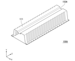
- first bead 150A may be formed on the top plate portion 111.
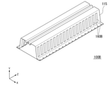
- the second bead 160 is formed from the first corner portion 113 to the second corner portion 117, as in the structural member 100B of the second modification shown in FIG.
- the second bead 160B may be formed only in the center of the side wall portion 115 in the height direction.
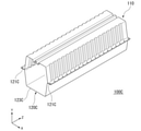
- the joining member 120 In the structural member 100 according to the first embodiment, one steel plate is used as the joining member 120, but as in the structural member 100C of the third modification shown in FIG. 9, the pair of flange portions 121C and 121C and the top plate A hat-shaped member having the portion 123C may be used as the joining member 120C.
- the top plate portion 123C of the joining member 120C corresponds to the top plate facing portion 123 of the structural member 100 according to the first embodiment.
- the side wall portion of the joining member 120C is flat, but a bead extending in the height direction may be formed.
- the structural member 100 according to the present embodiment has a uniform cross section along the longitudinal direction Z, but may have a different cross section along the longitudinal direction Z.
- the structural member 100 may be curved in the longitudinal direction Z, or the cross section perpendicular to the longitudinal direction Z may change.
- the cross sections of the first bead 150 and the second bead 160 are trapezoidal, but the cross sections may be rectangular, semicircular, or wedge-shaped.
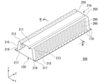
- the structural member 200 according to the second embodiment of the present invention will be described.
- the first bead 150 is formed in the central portion of the top plate portion 111 of the hat-shaped member 110 in the width direction X.
- the structural member 200 according to the present embodiment is different from the structural member 100 according to the first embodiment in that the first bead is formed in the vicinity of the end portion of the top plate portion of the hat-shaped member in the width direction X.
- the same reference numerals are used for configurations that overlap with those described in the first embodiment, such as the side wall portion 115 and the joining member 120, and the description thereof will be omitted.
- the structural member 200 is a member having a closed cross-section structure composed of a hat-shaped member 210 and a joining member 120.
- Examples of the application of the structural member 200 include a B-pillar, a side sill, a bumper line force, and the like.
- the structural member 200 according to the present embodiment is installed in the automobile in a posture in which the hat type member 210 faces the outside of the vehicle and the joining member 120 faces the inside of the vehicle. It is a part that assumes.
- FIG. 11 is a cross-sectional view taken along the line BB'of FIG.
- the hat-shaped member 210 includes a top plate portion 211 extending along the longitudinal direction Z and first corner portions 213, 213 formed at both ends of the top plate portion 211 in the width direction X.
- first corner portions 213, 213 formed at both ends of the top plate portion 211 in the width direction X.
- second corner portion 217, 217 formed at an end of the pair of side wall portions 215, 215 opposite to the first corner portions 213, 213. It has a pair of extending flange portions 219 and 219.
- first beads 250, 250 are formed in parallel on the top plate portion 211 along the longitudinal direction Z in the width direction X. As shown in FIG. 11, each of the first beads 250 and 250 is arranged so that the center in the width direction of the first bead 250 is arranged in the vicinity portions P at both ends of the width direction X of the top plate portion 211. It is formed so as to bulge inward from the top plate portion 211.
- the vicinity portion P is the width of the top plate portion 211 in the width direction X from the boundary point between the top plate portion 211 and the first corner portion 213 in the cross section perpendicular to the longitudinal direction Z of the structural member 200. It is a region up to a point where the separation distance is 1/4 of W.
- each of the first beads 250, 250 is from the boundary point between the top plate portion 211 and the first corner portion 213 to the point where the separation distance is 20 mm in the cross section perpendicular to the longitudinal direction Z. It may be formed so as to bulge inward from the top plate portion 211 so that the boundary point between the first bead 250 and the top plate portion 211 is located in the region.
- a plurality of second beads 260 are formed in parallel on the pair of side wall portions 215 and 215 along the direction intersecting the longitudinal direction Z.
- the structural member 200 according to the present embodiment described above forms a first bead 250, 250 and a second bead 260 on at least one of a pair of side wall portions 215, 215 in a cross section perpendicular to the longitudinal direction Z. It has a vertical cross-section.
- the top plate portion Deformation resistance to compressive stress (A) along the longitudinal direction Z generated in 211, deformation resistance to compressive stress (B) along the direction Z intersecting the longitudinal direction Z generated in the side wall portion 215, and deformation resistance to be generated in the joining member 120.
- Deformation resistance against tensile stress (C) along the longitudinal direction Z can be exhibited in combination.
- the first corner portion 213 and the first bead 250 are arranged at a short distance. Therefore, in the region from the first corner portion 213 to the first bead 250, the bending rigidity in the height direction Y of the cross section intersecting the longitudinal direction Z can be effectively improved.
- the first corner portion 213 is a portion where compressive stress in the longitudinal direction Z is generated when the structural member 100 is bent and deformed like the top plate portion 211, the first corner portion 213 is formed on the side wall portion 215.
- the deformation resistance of the first corner portion 213 to the compressive stress in the longitudinal direction Z is weakened.
- the structural member 200 according to the present embodiment since the first bead 250 is formed in the vicinity of the first corner portion 213, the deformation resistance of the first corner portion 213 to the compressive stress in the longitudinal direction Z. Can be efficiently compensated for weakening. Therefore, as shown in FIG. 12, the top plate portion 211 does not undergo large bending deformation at an early stage, and the bending of the side wall portion 215 can also be suppressed. Therefore, the load capacity at the initial stage of the stroke can be dramatically improved, and the collision safety performance can be further improved as compared with the structural member 100 according to the first embodiment.
- Examples 1 to 7 include a hat-shaped member to which a steel plate having a plate thickness of 0.8 mm and a tensile strength of 2.5 GPa class is applied, and a joining member to which a steel plate having a plate thickness of 0.8 mm and a tensile strength of 440 MPa class is applied.
- a simulation model of the constructed structural members was prepared. Regarding the simulation model of the structural member, the first bead and the second bead were appropriately applied, and the maximum load at the initial stage of the stroke was evaluated by the simulation assuming three-point bending.
- the basic conditions are as follows.
- the inclination angle of the side wall of the bead of the first bead is the same as the inclination angle of the side wall of the hat-shaped member.
- Top plate width W 90 mm Height of side wall H: 60 mm Radius of curvature of the first corner (inside bending): 5 mm Radius of curvature of the second corner (inside bending): 5 mm
- Overall length L of structural member 800 mm Spot welding: 40 mm pitch
- Top plate facing part width 130 mm
- Table 1 shows the evaluation results of the bead application conditions and the maximum load at the initial stage of the stroke.
- Example 5 to 7 in which the first bead and the second bead are formed in a complex manner, the deformation resistance to the compressive stress along the longitudinal direction Z generated in the top plate portion and the longitudinal direction generated in the side wall portion.
- the deformation resistance against the compressive stress along the direction intersecting Z and the deformation resistance against the tensile stress along the longitudinal direction Z generated in the joining member are exhibited in combination, and the load capacity at the initial stage of the stroke is improved.
- Example 6 and Example 7 in Example 7 in which one first bead is arranged at both ends, compared with Example 6 in which two first beads are arranged in the center. It was shown that the load capacity at the initial stage of the stroke is increased by 1.5 times or more.
- Example 1A a three-point bending is performed on a simulation model of a structural member in which the hat-shaped member of Example 1 is changed to a hat-shaped member to which a steel plate having a plate thickness of 1.6 mm and a tensile strength of 2.5 GPa is applied.
- the maximum load at the beginning of the stroke was evaluated by the assumed simulation.
- Examples 4A, 6A, 7A the hat-shaped member of Examples 4, 6 and 7 is changed to a hat-shaped member to which a steel plate having a plate thickness of 1.6 mm and a tensile strength of 2.5 GPa is applied.
- the maximum load at the beginning of the stroke was evaluated by the simulation model assuming three-point bending.
- the ratio of the maximum load obtained in Examples 4A, 6A, and 7A was calculated when the maximum load obtained in Example 1A was set to a reference value of 1.0.
- Example 1B a three-point bending is performed on a simulation model of a structural member in which the hat-shaped member of Example 1 is changed to a hat-shaped member to which a steel plate having a plate thickness of 0.8 mm and a tensile strength of 1.5 GPa is applied.
- the maximum load at the beginning of the stroke was evaluated by the assumed simulation.
- Examples 4B, 6B, 7B the hat-shaped member of Examples 4, 6 and 7 is changed to a hat-shaped member to which a steel plate having a plate thickness of 0.8 mm and a tensile strength of 1.5 GPa is applied.
- the maximum load at the beginning of the stroke was evaluated by the simulation model assuming three-point bending.
- the ratio of the maximum load obtained in Examples 4B, 6B, and 7B was calculated when the maximum load obtained in Example 1B was set to a reference value of 1.0.
- Example 1C a three-point bending is performed on a simulation model of a structural member in which the hat-shaped member of Example 1 is changed to a hat-shaped member to which a steel plate having a plate thickness of 1.6 mm and a tensile strength of 1.5 GPa is applied.
- the maximum load at the beginning of the stroke was evaluated by the assumed simulation.
- Examples 4C, 6C, 7C the hat-shaped member of Examples 4, 6 and 7 is changed to a hat-shaped member to which a steel plate having a plate thickness of 1.6 mm and a tensile strength of 1.5 GPa is applied.
- the maximum load at the beginning of the stroke was evaluated by bending at three points in the simulation model of.
- the ratio of the maximum load obtained in Examples 4C, 6C, and 7C was calculated when the maximum load obtained in Example 1C was set to a reference value of 1.0.
- the evaluation results are shown in Table 2.
- FIG. 14 is a graph showing the results of Table 2 collectively. From this graph, according to the present invention, an excellent load capacity can be exhibited at the initial stage of the stroke regardless of the plate thickness and strength, and when one first bead is arranged at both ends of the top plate portion. It was shown that a higher load capacity can be exhibited when the wall thickness is reduced. In addition, even when the hat-shaped member is thinned, it is possible to suppress the decrease in deformation resistance due to the decrease in plate thickness, and it is possible to demonstrate excellent collision safety performance even when a thin-walled, high-strength material is used. Was shown to be. Further, the effect of suppressing the decrease in deformation resistance when the hat-shaped member is thinned is remarkable in Examples 7 and 7B in which one first bead is arranged at both ends of the top plate portion. Was shown.
- the present invention it is possible to provide a structural member capable of exhibiting excellent collision safety performance by improving the load capacity at the initial stage of the deformation of the deformation in the local buckling mode.
Abstract
Description
特許文献2には、上部ウェブ、下部ウェブの一方又は両方に、車両の前後方向に略平行な凹状又は凸状のビードを有する車両用金属製アブソーバが開示されている。
(1)本発明の第一の態様は、長手方向に延びる天板部と、前記天板部の幅方向の両端部に形成された第一コーナ部を介して延在する一対の側壁部と、前記一対の側壁部における前記第一コーナ部とは反対側の端部に形成された第二コーナ部を介して延在する一対のフランジ部と、を有するハット型部材と、前記ハット型部材の前記一対のフランジ部に接合される一対の接合部と、前記ハット型部材の前記天板部に対向する天板対向部と、を有する接合部材と、を備え、前記天板部に、前記長手方向に沿って延在する第一ビードが形成され、前記一対の側壁部に、前記長手方向に交差する方向に沿って延在する第二ビードが二本以上形成される自動車車体の構造部材である。 Specific embodiments of the present invention are as follows.
(1) The first aspect of the present invention is a top plate portion extending in the longitudinal direction and a pair of side wall portions extending through first corner portions formed at both ends in the width direction of the top plate portion. A hat-shaped member having a pair of flange portions extending through a second corner portion formed at an end portion of the pair of side wall portions opposite to the first corner portion, and the hat-shaped member. A joining member having a pair of joining portions to be joined to the pair of flange portions and a top plate facing portion facing the top plate portion of the hat-shaped member is provided on the top plate portion. A structural member of an automobile body in which a first bead extending along the longitudinal direction is formed, and two or more second beads extending along the direction intersecting the longitudinal direction are formed on the pair of side wall portions. Is.
(3)上記(2)に記載の自動車車体の構造部材では、前記長手方向に垂直な断面において、前記天板部と前記第一コーナ部との境界点から、前記幅方向に前記天板部の幅の1/4の離間距離となる点までの領域に、前記第一ビードの前記幅方向の中心が位置するように前記第一ビードが形成されてもよい。
(4)上記(2)に記載の自動車車体の構造部材では、前記長手方向に垂直な断面において、前記天板部と前記第一コーナ部との境界点から、20mmの離間距離となる点までの領域に、前記第一ビードと天板部との境界点が位置するように前記第一ビードが形成されてもよい。
(5)上記(1)~(4)のいずれか一項に記載の自動車車体の構造部材では、前記第二ビードは、前記第一コーナ部から延在してもよい。
(6)上記(5)に記載の自動車車体の構造部材では、前記第二ビードは、前記第二コーナ部まで延在してもよい。 (2) In the structural member of the automobile body according to the above (1), two or more of the first beads may be formed in parallel in the width direction.
(3) In the structural member of the automobile body according to (2) above, the top plate portion in the width direction from the boundary point between the top plate portion and the first corner portion in the cross section perpendicular to the longitudinal direction. The first bead may be formed so that the center of the first bead in the width direction is located in a region up to a point having a separation distance of 1/4 of the width of the first bead.
(4) In the structural member of the automobile body according to (2) above, in the cross section perpendicular to the longitudinal direction, from the boundary point between the top plate portion and the first corner portion to a point having a separation distance of 20 mm. The first bead may be formed so that the boundary point between the first bead and the top plate portion is located in the region of.
(5) In the structural member of the automobile body according to any one of (1) to (4) above, the second bead may extend from the first corner portion.
(6) In the structural member of the automobile body according to (5) above, the second bead may extend to the second corner portion.
(8)上記(1)~(7)のいずれか一項に記載の自動車車体の構造部材では、前記第一ビードの深さ/幅で算出されるアスペクト比が0.25~4.0であってもよい。
(9)上記(1)~(8)のいずれか一項に記載の自動車車体の構造部材では、前記第二ビードの幅が10mm~60mmであり、前記第二ビードの深さが2mm~10mmであってもよい。
(10)上記(1)~(9)のいずれか一項に記載の自動車車体の構造部材では、前記第二ビードの深さ/幅で算出されるアスペクト比が0.05~1.0であってもよい。
(11)上記(1)~(10)のいずれか一項に記載の自動車車体の構造部材では、前記ハット型部材の前記天板部が板厚1.2mm以下の鋼板により形成されていてもよい。(12)上記(1)~(11)のいずれか一項に記載の自動車車体の構造部材では、前記ハット型部材の前記天板部が引張強さ980MPa以上の鋼板により形成されていてもよい。
(13)上記(1)~(12)のいずれか一項に記載の自動車車体の構造部材では、前記ハット型部材が焼き入れ部材であってもよい。 (7) In the structural member of the automobile body according to any one of (1) to (6) above, the width of the first bead is 5 mm to 20 mm, and the depth of the first bead is 5 mm to 20 mm. It may be.
(8) In the structural member of the automobile body according to any one of (1) to (7) above, the aspect ratio calculated by the depth / width of the first bead is 0.25 to 4.0. There may be.
(9) In the structural member of the automobile body according to any one of (1) to (8) above, the width of the second bead is 10 mm to 60 mm, and the depth of the second bead is 2 mm to 10 mm. It may be.
(10) In the structural member of the automobile body according to any one of (1) to (9) above, the aspect ratio calculated by the depth / width of the second bead is 0.05 to 1.0. There may be.
(11) In the structural member of the automobile body according to any one of (1) to (10) above, even if the top plate portion of the hat-shaped member is formed of a steel plate having a plate thickness of 1.2 mm or less. good. (12) In the structural member of the automobile body according to any one of (1) to (11) above, the top plate portion of the hat-shaped member may be formed of a steel plate having a tensile strength of 980 MPa or more. ..
(13) In the structural member of the automobile body according to any one of (1) to (12) above, the hat-shaped member may be a hardened member.
このうち、3点曲げ特性は、局部座屈モードの3点曲げ特性と、壁面座屈モードの3点曲げ特性と、に分類される。
局部座屈モードの3点曲げ特性及び壁面座屈モードの3点曲げ特性は、図1の(a)及び(b)に示すように、インパクタが部品に直接衝突する3点曲げ試験を行うことで得られる3点曲げ特性により評価することが多い。
局部座屈モードの3点曲げ特性では、3点曲げ試験において荷重を支持する支点間の距離が長い条件で、インパクタによる荷重負荷位置での屈曲変形が主体となる。
壁面座屈モードの3点曲げ特性では、3点曲げ試験において荷重を支持する支点間の距離が短い条件で、インパクタによる荷重負荷位置を中心に側壁が部品高さ方向に潰される変形が主体となる。
また、モーメント曲げ特性は、図1の(c)に示すように、部品の圧潰部にインパクタ等が接触しないモーメント曲げ試験を行うことで得られるモーメント曲げ特性で評価することが多い。 The bending and crushing characteristics of automobile parts are the three-point bending characteristics when the impact of a collision is directly applied to the crushed part of the part and deformed, and the bending and crushing characteristics when the impact of a collision is indirectly applied to the crushed part of the part and deformed. It is roughly divided into moment bending characteristics.
Of these, the three-point bending characteristics are classified into three-point bending characteristics in the local buckling mode and three-point bending characteristics in the wall surface buckling mode.
For the 3-point bending characteristics in the local buckling mode and the 3-point bending characteristics in the wall buckling mode, perform a 3-point bending test in which the impactor directly collides with the component as shown in FIGS. 1 (a) and 1 (b). It is often evaluated based on the three-point bending characteristics obtained in.
In the three-point bending characteristic in the local buckling mode, bending deformation at the load-bearing position by the impactor is the main component under the condition that the distance between the fulcrums supporting the load is long in the three-point bending test.
In the three-point bending characteristic of the wall buckling mode, the main component is deformation in which the side wall is crushed in the component height direction around the load load position by the impactor under the condition that the distance between the fulcrums that support the load is short in the three-point bending test. Become.
Further, as shown in FIG. 1 (c), the moment bending characteristic is often evaluated by the moment bending characteristic obtained by performing a moment bending test in which the impactor or the like does not come into contact with the crushed portion of the component.
(あ)圧潰部がインパクタに接触する3点曲げでは、部品の長手方向の曲げ内側の圧縮応力と曲げ外側の引張応力に加えて、部品の高さ方向に圧縮応力が生じること。
(い)部品の高さ方向の圧縮応力は部品の側壁に生じることから、特に素材の板厚が薄い場合には、高さ方向の圧縮応力により側壁が容易に座屈変形してしまい、局部座屈モードを想定した部品であっても変形の初期において壁面座屈モードに近い変形状態になる場合があること。
(う)壁面座屈モードに近い変形状態になった場合、側壁の座屈変形が容易に生じると、壁面座屈モードとしての良好な3点曲げ特性が得られないだけでなく、側壁が潰れることで圧潰部の部品高さが減少して、長手方向に交差する断面の高さ方向の曲げ剛性が低下するため、その後の変形において局部座屈モードの変形状態になったとしても局部座屈モードとしての良好な3点曲げ特性も得られない場合があること。
(え)従って、曲げ内側の圧縮応力に対する変形抵抗、曲げ外側の引張応力に対する変形抵抗、及び、高さ方向の圧縮応力に対する変形抵抗を同時に高めることができる部品形状とすることで、局部座屈モードの変形における、特にストローク初期における耐荷重を向上することができ、従来よりも更に優れた衝突安全性能を発揮することが可能となること。 The present inventor examined the shape of a component for enhancing the collision safety performance against deformation of the local buckling mode as shown in FIG. 1 (a), and obtained the following findings.
(A) In the three-point bending where the crushed part contacts the impactor, in addition to the compressive stress inside the bend in the longitudinal direction of the component and the tensile stress outside the bend, compressive stress is generated in the height direction of the component.
(I) Since the compressive stress in the height direction of the component is generated on the side wall of the component, the side wall is easily buckled and deformed by the compressive stress in the height direction, especially when the plate thickness of the material is thin. Even a part that assumes a buckling mode may be in a deformed state close to the wall buckling mode at the initial stage of deformation.
(C) In the case of a deformation state close to the wall surface buckling mode, if the side wall buckling deformation easily occurs, not only the good three-point bending characteristic as the wall surface buckling mode cannot be obtained, but also the side wall is crushed. As a result, the height of the parts in the crushed portion decreases, and the bending rigidity in the height direction of the cross section intersecting the longitudinal direction decreases. Therefore, even if the deformation is in the local buckling mode in the subsequent deformation, the local buckling It may not be possible to obtain good 3-point bending characteristics as a mode.
(E) Therefore, by making the component shape that can simultaneously increase the deformation resistance against the compressive stress inside the bend, the deformation resistance against the tensile stress outside the bend, and the deformation resistance against the compressive stress in the height direction, local buckling It is possible to improve the load capacity in the deformation of the mode, especially at the initial stage of the stroke, and to exhibit even better collision safety performance than before.
また、長手方向Zに垂直な面における、天板部に平行な方向を幅方向Xと呼称し、長手方向Zと幅方向Xに垂直な方向を高さ方向Yと呼称する。
構造部材の軸線から離れる方向を外方と呼称し、その反対方向を内方と呼称する。 In the following description, the axial direction of the structural member, that is, the direction in which the axis extends is referred to as the longitudinal direction Z.
Further, the direction parallel to the top plate portion on the plane perpendicular to the longitudinal direction Z is referred to as the width direction X, and the direction perpendicular to the longitudinal direction Z and the width direction X is referred to as the height direction Y.
The direction away from the axis of the structural member is called the outer direction, and the opposite direction is called the inner direction.
以下、本発明の第一実施形態に係る自動車車体の構造部材100(以下、構造部材100と呼称する)について説明する。 (First Embodiment)
Hereinafter, the structural member 100 (hereinafter referred to as the structural member 100) of the automobile body according to the first embodiment of the present invention will be described.
図2に示すように、構造部材100は、ハット型部材110と接合部材120とにより構成される閉断面構造の部材である。構造部材100の適用例としては、Bピラー、サイドシル、バンパリーンフォース等が挙げられる。 First, the schematic configuration of the
As shown in FIG. 2, the
図3は、図2のA-A’断面図である。図3に示すように、ハット型部材110は、長手方向Zに沿って延在する天板部111と、天板部111の幅方向Xの両端に形成された第一コーナ部113,113を介して延在する一対の側壁部115,115と、一対の側壁部115,115における第一コーナ部113,113とは反対側の端部に形成された第二コーナ部117,117を介して延在する一対のフランジ部119,119とを有する。
ハット型部材110は、樹脂板、CFRP(Carbon Fiber Reinforced Plastic)板、又は金属板(アルミ板、アルミ合金板、ステンレス板、チタン板、又は鋼板等)からなる部材であればよい。 (Hat type member)
FIG. 3 is a cross-sectional view taken along the line AA'of FIG. As shown in FIG. 3, the hat-shaped
The hat-shaped
また、ハット型部材110は、鋼板をオーステナイト域の高温まで加熱した後に金型でプレス成形を実施すると同時に、その金型内において焼入れ処理を実施するホットスタンプ加工により成形されてもよい。従って、ハット型部材110は、焼き入れ部材であってもよい。 The hat-shaped
Further, the
天板部111は、図1に示す局部座屈モードの3点曲げ試験における、インパクタが直接接触する部位に相当する。
本実施形態に係る構造部材100は、ハット型部材110が車外側に対向する姿勢で自動車に設置される。このため、車外側からの衝撃荷重が天板部111に入力されて構造部材100に曲げ変形が生じると、天板部111には長手方向Zに沿う圧縮応力が発生する。 (Top plate)
The
The
更に、衝突安全性能の観点からは、天板部111は、引張強さが980MPa以上の鋼板により形成されていることが好ましく、引張強さが1470MPa以上の鋼板で形成されていることがより好ましい。 From the viewpoint of weight reduction, the
Further, from the viewpoint of collision safety performance, the
天板部111に形成される第一ビード150については後述する。 The width W of the
The
一対の側壁部115,115は、天板部111の幅方向Xの両端部に形成された第一コーナ部113,113を介して延在する。尚、第一コーナ部113,113は、例えば1mm~10mmの曲率半径のR部を有する。
本実施形態に係る構造部材100は、ハット型部材110が車外側に対向する姿勢で自動車に設置されるため、車外側からの衝撃荷重が天板部111に入力されて構造部材100に曲げ変形が生じると、一対の側壁部115,115には長手方向Zに交差する方向に沿う圧縮応力、すなわち、構造部材100の長手方向Zに垂直な断面における、側壁部115に沿う圧縮応力が発生する。
側壁部115に形成される第二ビード160については後述する。 (Wall wall)
The pair of
Since the
The
図2~図5に示すように、一対の側壁部115,115における、第一コーナ部113,113とは反対側の端部には、第二コーナ部117,117が形成される。一対のフランジ部119,119は、第二コーナ部117,117から外方に向けて延在するように形成される。
フランジ部119には、接合部材120に接合するためのスポット溶接部170が長手方向Zに所定のピッチで形成されている。なお、スポット溶接は接合するための手段の一例であり、レーザ溶接やろう付けであってもよい。 (Flange part)
As shown in FIGS. 2 to 5, the
以下、接合部材120について説明する。
接合部材120は、ハット型部材110に接合される部材である。本実施形態に係る構造部材100は、接合部材120が車内側に対向する姿勢で自動車に設置されるため、車外側からの衝撃荷重が天板部111に入力されて構造部材100に曲げ変形が生じると、接合部材120には長手方向Zに沿う引張応力が発生する。
従って、接合部材120がハット型部材110に接合されることにより、長手方向Zに沿う引張応力に対する変形抵抗を高めることができるため、高い衝突安全性能を発揮することが可能となる。
また、接合部材120は、ハット型部材110に接合されることにより、構造部材100に曲げ変形が生じた際に側壁部115が幅方向Xに開くことを防ぐことができる。従って、3点曲げ特性の低下を防ぎ、高い衝突安全性能を発揮することが可能となる。 (Joining member)
Hereinafter, the joining
The joining
Therefore, by joining the joining
Further, by joining the joining
接合部材120は、樹脂板、CFRP(Carbon Fiber Reinforced Plastic)板、又は金属板(アルミ板、アルミ合金板、ステンレス板、チタン板、又は鋼板等)からなる部材であればよい。
接合部材120の引張強さ及び板厚は、特に限定されるものではない。前述のように車外側からの衝撃荷重が天板部111に入力されて構造部材100に曲げ変形が生じると、接合部材120には長手方向Zに沿う引張応力が発生する。仮に圧縮応力が発生する場合、圧縮応力による座屈変形には部材の板厚や強度が大きく影響するが、引張応力の場合は、引張変形により部材が破断しない範囲で薄い板厚や低い強度の素材を使用することができる。このため、例えば接合部材120の引張強さ及び板厚は、ハット型部材110の天板部111よりも低い引張強さであっても、薄い板厚であってもよい。ただし、接合部材120は、焼き入れ部材であってもよい。 As shown in FIGS. 2 and 3, in the
The joining
The tensile strength and plate thickness of the joining
一対の接合部121,121は、スポット溶接等で接合されるハット型部材110の一対のフランジ部119,119が面接触する部位である。
天板対向部123は、接合部材120の接合部121を除く部位であって、ハット型部材110の天板部111に対向する部位である。天板対向部123は、天板部111を内方から支える構造ではない。すなわち、天板対向部123は、天板部111の内方の表面に接触していない。構造部材100の閉断面で囲まれる面積あたりの断面周長を小さくすることができるため、部材重量あたりで得られる3点曲げ特性(例えば最大荷重)を効率よく高めることができる。すなわち、軽量化が実現できる。
本実施形態に係る構造部材100では、接合部材120は一枚の平板状の鋼板で構成されるため、接合部121と天板対向部123は同一面内で互いに隣接する領域である。 As shown in FIG. 3, the joining
The pair of
The top
In the
天板部111には長手方向Zに沿って二本の第一ビード150,150が並列して形成される。
図3に示すように、第一ビード150は、天板部111の幅方向Xの中央部分において、天板部111から内方に向けて膨出するように形成される。
第一ビード150は、天板部111側の端部に所定の曲率半径のR部を有する場合がある。その場合、第一ビード150は、第一ビード150のR部を介して天板部111に繋がる。 (First bead)
Two
As shown in FIG. 3, the
The
一対のビード側壁151,151は、天板部111から屈曲して内方に向かって延在する。
ビード底板152は、一対のビード側壁151,151における天板部111とは反対側の端部間を繋ぐように延在する。 As shown in FIG. 3, the
The pair of
The
第一ビード150が長手方向Zに沿って幅が変化する形状である場合、上記離間距離が最大となる断面における離間距離を幅w1とする。 The width w1 of the
When the
一対の側壁部115,115には長手方向Zに交差する方向に沿って複数の第二ビード160が並列して形成される。
図4は、本実施形態に係る構造部材100の概略平面図であり、図5は、図4の部分Bの拡大図である。
図4及び図5に示すように、第二ビード160は、側壁部115から内方に向けて膨出するように形成されている。
第二ビード160は、側壁部115側の端部に所定の曲率半径のR部を有する場合がある。その場合、第二ビード160は、第二ビード160のR部を介して側壁部115に繋がる。
このような第二ビード160が設けられることにより、側壁部115に発生する長手方向Zに交差する方向に沿う圧縮応力に対する変形抵抗を高めることができる。これにより、側壁部115での早期の座屈変形が抑制されて最大荷重が増加する。
第二ビード160は、一対の側壁部115,115のそれぞれの側壁部115に形成されることが好ましい。これにより、第二ビード160が一方の側壁部115のみに形成される場合と比べて、側壁部115に発生する長手方向Zに交差する方向に沿う圧縮応力に対する変形抵抗を更に高めることができる。 (Second bead)
A plurality of
FIG. 4 is a schematic plan view of the
As shown in FIGS. 4 and 5, the
The
By providing such a
The
第二ビード160が、第一コーナ部113から延在するように形成されていることにより、第二ビード160が第一コーナ部113の高さ方向Yの変形抵抗にも寄与し、第一コーナ部113が潰れにくくなる。第一コーナ部113が潰れにくくなることで、第一コーナ部113と繋がる側壁部115の上部も更に潰れにくくなる。第一コーナ部113及び側壁部115が潰れにくくなることで、構造部材100の高さ減少に伴う、長手方向Zに交差する断面の高さ方向Yの曲げ剛性の低下を抑制し、局部座屈モードの3点曲げ特性の低下を防ぐことができるため、好ましい。尚、このように、第二ビード160が、第一コーナ部113から延在するように形成されている場合には、第一コーナ部113は、長手方向Zに沿って、後述する第二ビード160のビード底板162の部位と、第二ビード160が形成されていない側壁部115の部位とによる段差が形成されることになる。 In the
Since the
一対のビード側壁161,161は、側壁部115から屈曲して内方に向かって延在する。
ビード底板162は、一対のビード側壁161,161における側壁部115とは反対側の端部間を繋ぐように延在する。 As shown in FIG. 5, the
The pair of
The
また、複数の第二ビード160は、側壁部115に均等のビード間距離で並んで形成される必要はなく、例えば、三本の第二ビード160が形成される場合、二つのビード間距離は異なる値であってよい。
更に、複数の第二ビード160は、一対の側壁部115,115において、必ずしも長手方向Zの同じ位置に形成される必要はない。例えば一方の側壁部115に形成された第二ビード160と同じ長手方向Zの位置において、他方の側壁部115には第二ビード160が形成されていなくてもよい。 It should be noted that the plurality of
Further, the plurality of
Further, the plurality of
第二ビード160が長手方向Zに交差する方向に沿って幅が変化する形状である場合、上記離間距離が最大となる断面における離間距離を幅w2とする。 The width w2 of the
When the width of the
第一実施形態に係る構造部材100では、二本の第一ビードが天板部111に形成されているが、図7に示す第一変形例の構造部材100Aのように、一本の第一ビード150Aが天板部111に形成されていてもよい。 (First modification)
In the
第一実施形態に係る構造部材100では、第二ビード160は、第一コーナ部113から第二コーナ部117に亘り形成されているが、図8に示す第二変形例の構造部材100Bのように、側壁部115の高さ方向の中央のみに第二ビード160Bが形成されていてもよい。 (Second modification)
In the
第一実施形態に係る構造部材100では、一枚の鋼板を接合部材120として用いるが、図9に示す第三変形例の構造部材100Cのように、一対のフランジ部121C,121Cと、天板部123Cとを有するハット型部材を接合部材120Cとして用いてもよい。この場合、接合部材120Cの天板部123Cが、第一実施形態に係る構造部材100における天板対向部123に対応する。尚、図9に示す例では接合部材120Cの側壁部は平面であるが、高さ方向に延びるビードが形成されていてもよい。 (Third modification example)
In the
本実施形態に係る構造部材100では、第一ビード150及び第二ビード160の断面が台形形状であるが、断面は矩形状、半円形状、又は楔形状であってもよい。 The
In the
以下、本発明の第二実施形態に係る構造部材200について説明する。
第一実施形態に係る構造部材100では、ハット型部材110の天板部111の幅方向Xの中央部分に、第一ビード150を形成する構成としている。
本実施形態に係る構造部材200では、ハット型部材の天板部の幅方向Xの端部近傍部分に、第一ビードを形成する点で、第一実施形態に係る構造部材100と異なる。
側壁部115や接合部材120など、第一実施形態での説明と重複する構成については同一符号を用いて説明を省略する。 (Second embodiment)
Hereinafter, the
In the
The
The same reference numerals are used for configurations that overlap with those described in the first embodiment, such as the
図10に示すように、構造部材200は、ハット型部材210と接合部材120とにより構成される閉断面構造の部材である。構造部材200の適用例としては、Bピラー、サイドシル、バンパリーンフォース等が挙げられる。 First, with reference to FIG. 10, the schematic configuration of the
As shown in FIG. 10, the
図11は、図10のB-B’断面図である。図11に示すように、ハット型部材210は、長手方向Zに沿って延在する天板部211と、天板部211の幅方向Xの両端に形成された第一コーナ部213,213を介して延在する一対の側壁部215,215と、一対の側壁部215,215における第一コーナ部213,213とは反対側の端部に形成された第二コーナ部217,217を介して延在する一対のフランジ部219,219とを有する。 (Hat type member)
FIG. 11 is a cross-sectional view taken along the line BB'of FIG. As shown in FIG. 11, the hat-shaped
天板部211には長手方向Zに沿って二本の第一ビード250,250が幅方向Xに並列して形成される。
図11に示すように、それぞれの第一ビード250,250は、天板部211の幅方向Xの両端の近傍部分Pにおいて第一ビード250の幅方向の中心が配置されるように、且つ、天板部211から内方に向けて膨出するように形成される。 (First bead)
Two
As shown in FIG. 11, each of the
一対の側壁部215,215には長手方向Zに交差する方向に沿って複数の第二ビード260が並列して形成される。 (Second bead)
A plurality of
特に、第一ビード250は、天板部211の幅方向Xの両端の近傍部分Pにおいて形成されていることから、第一コーナ部213と第一ビード250とが近い距離で配置される。従って、第一コーナ部213から第一ビード250までの領域において、長手方向Zに交差する断面の高さ方向Yの曲げ剛性を効果的に向上することができる。また、第一コーナ部213は、天板部211と同様、構造部材100に曲げ変形が生じた際には長手方向Zの圧縮応力が発生する部位であるため、側壁部215に形成された第二ビード260が第一コーナ部213の近傍まで延びている場合には、第一コーナ部213の長手方向Zの圧縮応力への変形抵抗が弱まる。しかしながら、本実施形態に係る構造部材200によれば、第一ビード250が第一コーナ部213の近傍に形成されていることにより、第一コーナ部213の長手方向Zの圧縮応力への変形抵抗が弱まることを効率よく補うことができる。このため図12に示すように、天板部211に早期に大きな撓み変形を生じさせることがなく、さらに側壁部215の撓みも抑制することができる。このため、ストローク初期における耐荷重を飛躍的に向上することができ、第一実施形態に係る構造部材100と比較して更に衝突安全性能を高めることができる。 The
In particular, since the
以下、本発明の効果を実施例により具体的に説明する。なお、以下に説明する実施例は、あくまでも本発明の一例であって、本発明を限定するものではない。 (Example)
Hereinafter, the effects of the present invention will be specifically described with reference to Examples. It should be noted that the examples described below are merely examples of the present invention and do not limit the present invention.
構造部材のシミュレーションモデルについて、第一ビードと第二ビードを適宜付与し、3点曲げを想定したシミュレーションによりストローク初期の最大荷重を評価した。基本条件は下記の通りである。尚、本実施例では、第一ビードのビード側壁の傾斜角は、ハット型部材の側壁部の傾斜角と同じ角度とした。
天板部の幅W:90mm
側壁部の高さH:60mm
第一コーナ部の曲率半径(曲げ内側):5mm
第二コーナ部の曲率半径(曲げ内側):5mm
構造部材の全長L:800mm
スポット溶接:40mmピッチ
天板対向部の幅:130mm Examples 1 to 7 include a hat-shaped member to which a steel plate having a plate thickness of 0.8 mm and a tensile strength of 2.5 GPa class is applied, and a joining member to which a steel plate having a plate thickness of 0.8 mm and a tensile strength of 440 MPa class is applied. A simulation model of the constructed structural members was prepared.
Regarding the simulation model of the structural member, the first bead and the second bead were appropriately applied, and the maximum load at the initial stage of the stroke was evaluated by the simulation assuming three-point bending. The basic conditions are as follows. In this embodiment, the inclination angle of the side wall of the bead of the first bead is the same as the inclination angle of the side wall of the hat-shaped member.
Top plate width W: 90 mm
Height of side wall H: 60 mm
Radius of curvature of the first corner (inside bending): 5 mm
Radius of curvature of the second corner (inside bending): 5 mm
Overall length L of structural member: 800 mm
Spot welding: 40 mm pitch Top plate facing part width: 130 mm

更に、実施例6と実施例7とを比較すると、両端部に一本ずつ第一ビードを配置した実施例7では、中央部に二本の第一ビードを配置した実施例6と比較してストローク初期における耐荷重が1.5倍以上高まることが示された。 On the other hand, in Examples 5 to 7 in which the first bead and the second bead are formed in a complex manner, the deformation resistance to the compressive stress along the longitudinal direction Z generated in the top plate portion and the longitudinal direction generated in the side wall portion. The deformation resistance against the compressive stress along the direction intersecting Z and the deformation resistance against the tensile stress along the longitudinal direction Z generated in the joining member are exhibited in combination, and the load capacity at the initial stage of the stroke is improved.
Further, comparing Example 6 and Example 7, in Example 7 in which one first bead is arranged at both ends, compared with Example 6 in which two first beads are arranged in the center. It was shown that the load capacity at the initial stage of the stroke is increased by 1.5 times or more.
同様に、実施例4A、6A、7Aとして、実施例4、6、7のハット型部材を、板厚1.6mm、引張強さ2.5GPaの鋼板を適用したハット型部材に変更した構造部材のシミュレーションモデルについて、3点曲げを想定したシミュレーションによりストローク初期の最大荷重を評価した。
そして、実施例1Aで得られた最大荷重を基準値1.0とした場合の、実施例4A、6A、7Aで得られた最大荷重の比率を算出した。 Further, as Example 1A, a three-point bending is performed on a simulation model of a structural member in which the hat-shaped member of Example 1 is changed to a hat-shaped member to which a steel plate having a plate thickness of 1.6 mm and a tensile strength of 2.5 GPa is applied. The maximum load at the beginning of the stroke was evaluated by the assumed simulation.
Similarly, as Examples 4A, 6A, 7A, the hat-shaped member of Examples 4, 6 and 7 is changed to a hat-shaped member to which a steel plate having a plate thickness of 1.6 mm and a tensile strength of 2.5 GPa is applied. The maximum load at the beginning of the stroke was evaluated by the simulation model assuming three-point bending.
Then, the ratio of the maximum load obtained in Examples 4A, 6A, and 7A was calculated when the maximum load obtained in Example 1A was set to a reference value of 1.0.
同様に、実施例4B、6B、7Bとして、実施例4、6、7のハット型部材を、板厚0.8mm、引張強さ1.5GPaの鋼板を適用したハット型部材に変更した構造部材のシミュレーションモデルについて、3点曲げを想定したシミュレーションによりストローク初期の最大荷重を評価した。
そして、実施例1Bで得られた最大荷重を基準値1.0とした場合の、実施例4B、6B、7Bで得られた最大荷重の比率を算出した。 Further, as Example 1B, a three-point bending is performed on a simulation model of a structural member in which the hat-shaped member of Example 1 is changed to a hat-shaped member to which a steel plate having a plate thickness of 0.8 mm and a tensile strength of 1.5 GPa is applied. The maximum load at the beginning of the stroke was evaluated by the assumed simulation.
Similarly, as Examples 4B, 6B, 7B, the hat-shaped member of Examples 4, 6 and 7 is changed to a hat-shaped member to which a steel plate having a plate thickness of 0.8 mm and a tensile strength of 1.5 GPa is applied. The maximum load at the beginning of the stroke was evaluated by the simulation model assuming three-point bending.
Then, the ratio of the maximum load obtained in Examples 4B, 6B, and 7B was calculated when the maximum load obtained in Example 1B was set to a reference value of 1.0.
同様に、実施例4C、6C、7Cとして、実施例4、6、7のハット型部材を、板厚1.6mm、引張強さ1.5GPaの鋼板を適用したハット型部材に変更した構造部材のシミュレーションモデルについて、3点曲げによりストローク初期の最大荷重を評価した。 そして、実施例1Cで得られた最大荷重を基準値1.0とした場合の、実施例4C、6C、7Cで得られた最大荷重の比率を算出した。
評価結果を表2に示す。 Further, as Example 1C, a three-point bending is performed on a simulation model of a structural member in which the hat-shaped member of Example 1 is changed to a hat-shaped member to which a steel plate having a plate thickness of 1.6 mm and a tensile strength of 1.5 GPa is applied. The maximum load at the beginning of the stroke was evaluated by the assumed simulation.
Similarly, as Examples 4C, 6C, 7C, the hat-shaped member of Examples 4, 6 and 7 is changed to a hat-shaped member to which a steel plate having a plate thickness of 1.6 mm and a tensile strength of 1.5 GPa is applied. The maximum load at the beginning of the stroke was evaluated by bending at three points in the simulation model of. Then, the ratio of the maximum load obtained in Examples 4C, 6C, and 7C was calculated when the maximum load obtained in Example 1C was set to a reference value of 1.0.
The evaluation results are shown in Table 2.

また、ハット型部材を薄肉化した場合であっても、板厚低下による変形抵抗の減少を抑制することができ、薄肉高強度の素材を用いても優れた衝突安全性能を発揮することが可能となることが示された。
更には、ハット型部材を薄肉化した場合において変形抵抗の減少を抑制する効果は、天板部の両端部に一本ずつの第一ビードを配置した実施例7と実施例7Bにおいて顕著であることが示された。 FIG. 14 is a graph showing the results of Table 2 collectively. From this graph, according to the present invention, an excellent load capacity can be exhibited at the initial stage of the stroke regardless of the plate thickness and strength, and when one first bead is arranged at both ends of the top plate portion. It was shown that a higher load capacity can be exhibited when the wall thickness is reduced.
In addition, even when the hat-shaped member is thinned, it is possible to suppress the decrease in deformation resistance due to the decrease in plate thickness, and it is possible to demonstrate excellent collision safety performance even when a thin-walled, high-strength material is used. Was shown to be.
Further, the effect of suppressing the decrease in deformation resistance when the hat-shaped member is thinned is remarkable in Examples 7 and 7B in which one first bead is arranged at both ends of the top plate portion. Was shown.
110、210 ハット型部材
111、211 天板部
113、213 第一コーナ部
115、215 側壁部
117、217 第二コーナ部
119、219 フランジ部
120、120C 接合部材
121 接合部
121C フランジ部
123 天板対向部
123C 天板部
150、150A、250 第一ビード
160、160B、260 第二ビード 100, 100A, 100B, 100C, 200
Claims (13)
- 長手方向に延びる天板部と、
前記天板部の幅方向の両端部に形成された第一コーナ部を介して延在する一対の側壁部と、
前記一対の側壁部における前記第一コーナ部とは反対側の端部に形成された第二コーナ部を介して延在する一対のフランジ部と、
を有するハット型部材と、
前記ハット型部材の前記一対のフランジ部に接合される一対の接合部と、
前記ハット型部材の前記天板部に対向する天板対向部と、
を有する接合部材と、
を備え、
前記天板部に、前記長手方向に沿って延在する第一ビードが形成され、
前記一対の側壁部に、前記長手方向に交差する方向に沿って延在する第二ビードが二本以上形成される
ことを特徴とする自動車車体の構造部材。 The top plate extending in the longitudinal direction and
A pair of side wall portions extending through the first corner portions formed at both ends in the width direction of the top plate portion, and
A pair of flange portions extending through a second corner portion formed at an end portion of the pair of side wall portions opposite to the first corner portion, and a pair of flange portions.
With a hat-shaped member
A pair of joints joined to the pair of flanges of the hat-shaped member,
The top plate facing portion facing the top plate portion of the hat type member and the top plate facing portion
With a joining member with
Equipped with
A first bead extending along the longitudinal direction is formed on the top plate portion.
A structural member of an automobile body, characterized in that two or more second beads extending along a direction intersecting the longitudinal direction are formed on the pair of side wall portions. - 前記第一ビードが二本以上、前記幅方向に並列して形成される
ことを特徴とする請求項1に記載の自動車車体の構造部材。 The structural member of an automobile body according to claim 1, wherein two or more of the first beads are formed in parallel in the width direction. - 前記長手方向に垂直な断面において、前記天板部と前記第一コーナ部との境界点から、前記幅方向に前記天板部の幅の1/4の離間距離となる点までの領域に、前記第一ビードの前記幅方向の中心が位置するように前記第一ビードが形成される
ことを特徴とする請求項2に記載の自動車車体の構造部材。 In the cross section perpendicular to the longitudinal direction, in the region from the boundary point between the top plate portion and the first corner portion to the point where the separation distance is 1/4 of the width of the top plate portion in the width direction. The structural member of an automobile body according to claim 2, wherein the first bead is formed so that the center of the first bead in the width direction is located. - 前記長手方向に垂直な断面において、前記天板部と前記第一コーナ部との境界点から、20mmの離間距離となる点までの領域に、前記第一ビードと天板部との境界点が位置するように前記第一ビードが形成される
ことを特徴とする請求項2に記載の自動車車体の構造部材。 In the cross section perpendicular to the longitudinal direction, the boundary point between the first bead and the top plate portion is located in the region from the boundary point between the top plate portion and the first corner portion to the point where the separation distance is 20 mm. The structural member of an automobile body according to claim 2, wherein the first bead is formed so as to be located. - 前記第二ビードは、前記第一コーナ部から延在する
ことを特徴とする請求項1~4のいずれか一項に記載の自動車車体の構造部材。 The structural member of an automobile body according to any one of claims 1 to 4, wherein the second bead extends from the first corner portion. - 前記第二ビードは、前記第二コーナ部まで延在する
ことを特徴とする請求項5に記載の自動車車体の構造部材。 The structural member of an automobile body according to claim 5, wherein the second bead extends to the second corner portion. - 前記第一ビードの幅が5mm~20mmであり、
前記第一ビードの深さが5mm~20mmである
ことを特徴とする請求項1~6のいずれか一項に記載の自動車車体の構造部材。 The width of the first bead is 5 mm to 20 mm.
The structural member of an automobile body according to any one of claims 1 to 6, wherein the depth of the first bead is 5 mm to 20 mm. - 前記第一ビードの深さ/幅で算出されるアスペクト比が0.25~4.0である
ことを特徴とする請求項1~7のいずれか一項に記載の自動車車体の構造部材。 The structural member of an automobile body according to any one of claims 1 to 7, wherein the aspect ratio calculated by the depth / width of the first bead is 0.25 to 4.0. - 前記第二ビードの幅が10mm~60mmであり、
前記第二ビードの深さが2mm~10mmである
ことを特徴とする請求項1~8のいずれか一項に記載の自動車車体の構造部材。 The width of the second bead is 10 mm to 60 mm, and the width of the second bead is 10 mm to 60 mm.
The structural member of an automobile body according to any one of claims 1 to 8, wherein the depth of the second bead is 2 mm to 10 mm. - 前記第二ビードの深さ/幅で算出されるアスペクト比が0.05~1.0である
ことを特徴とする請求項1~9のいずれか一項に記載の自動車車体の構造部材。 The structural member of an automobile body according to any one of claims 1 to 9, wherein the aspect ratio calculated by the depth / width of the second bead is 0.05 to 1.0. - 前記ハット型部材の前記天板部が板厚1.2mm以下の鋼板により形成されている
ことを特徴とする請求項1~10のいずれか一項に記載の自動車車体の構造部材。 The structural member of an automobile body according to any one of claims 1 to 10, wherein the top plate portion of the hat-shaped member is formed of a steel plate having a plate thickness of 1.2 mm or less. - 前記ハット型部材の前記天板部が引張強さ980MPa以上の鋼板により形成されている
ことを特徴とする請求項1~11のいずれか一項に記載の自動車車体の構造部材。 The structural member of an automobile body according to any one of claims 1 to 11, wherein the top plate portion of the hat-shaped member is formed of a steel plate having a tensile strength of 980 MPa or more. - 前記ハット型部材が焼き入れ部材である
ことを特徴とする請求項1~12のいずれか一項に記載の自動車車体の構造部材。 The structural member of an automobile body according to any one of claims 1 to 12, wherein the hat-shaped member is a hardened member.
Priority Applications (4)
| Application Number | Priority Date | Filing Date | Title |
|---|---|---|---|
| CN202180058691.9A CN116056956A (en) | 2020-07-31 | 2021-07-28 | Automobile body construction part |
| EP21849350.0A EP4190646A4 (en) | 2020-07-31 | 2021-07-28 | Structural member for automobile body |
| JP2022539517A JP7376835B2 (en) | 2020-07-31 | 2021-07-28 | Structural components of automobile bodies |
| US18/016,260 US20230271649A1 (en) | 2020-07-31 | 2021-07-28 | Structural member for automobile body |
Applications Claiming Priority (2)
| Application Number | Priority Date | Filing Date | Title |
|---|---|---|---|
| JP2020-130553 | 2020-07-31 | ||
| JP2020130553 | 2020-07-31 |
Publications (1)
| Publication Number | Publication Date |
|---|---|
| WO2022025098A1 true WO2022025098A1 (en) | 2022-02-03 |
Family
ID=80035693
Family Applications (1)
| Application Number | Title | Priority Date | Filing Date |
|---|---|---|---|
| PCT/JP2021/027843 WO2022025098A1 (en) | 2020-07-31 | 2021-07-28 | Structural member for automobile body |
Country Status (5)
| Country | Link |
|---|---|
| US (1) | US20230271649A1 (en) |
| EP (1) | EP4190646A4 (en) |
| JP (1) | JP7376835B2 (en) |
| CN (1) | CN116056956A (en) |
| WO (1) | WO2022025098A1 (en) |
Citations (8)
| Publication number | Priority date | Publication date | Assignee | Title |
|---|---|---|---|---|
| JPS5434914U (en) * | 1977-08-15 | 1979-03-07 | ||
| JP2009166557A (en) * | 2008-01-11 | 2009-07-30 | Toyota Motor Corp | Vehicle body structure of vehicle |
| JP4330652B2 (en) | 2007-03-28 | 2009-09-16 | ユニプレス株式会社 | Vehicle metal absorber, vehicle bumper system, automobile bumper absorber and automobile bumper system |
| JP5119477B2 (en) | 2008-05-30 | 2013-01-16 | 新日鐵住金株式会社 | Collision resistant reinforcing material for vehicle excellent in buckling resistance and manufacturing method thereof |
| JP2013220807A (en) * | 2012-04-19 | 2013-10-28 | Toyota Motor Corp | Vehicle body side structure |
| WO2017159425A1 (en) * | 2016-03-15 | 2017-09-21 | Jfeスチール株式会社 | Lap laser-welded joint, method for producing same, and automobile skeleton component |
| JP2020026151A (en) * | 2018-08-09 | 2020-02-20 | トヨタ自動車株式会社 | Vehicle body framework member |
| JP2020130553A (en) | 2019-02-19 | 2020-08-31 | 富士フイルム株式会社 | Endoscope system |
Family Cites Families (18)
| Publication number | Priority date | Publication date | Assignee | Title |
|---|---|---|---|---|
| SE516760C2 (en) * | 1999-12-14 | 2002-02-26 | Accra Teknik Ab | Bumper beam |
| JP4872541B2 (en) * | 2006-08-31 | 2012-02-08 | マツダ株式会社 | Automotive bumper structure |
| JP5543756B2 (en) * | 2009-11-05 | 2014-07-09 | アイシン精機株式会社 | Bumper device for vehicle |
| CN112867637A (en) * | 2018-10-24 | 2021-05-28 | 日本制铁株式会社 | Automobile framework component and electric automobile |
| JP6933203B2 (en) * | 2018-12-20 | 2021-09-08 | Jfeスチール株式会社 | Collision energy absorbing parts for automobiles, methods for manufacturing the collision energy absorbing parts for automobiles |
| WO2020170569A1 (en) * | 2019-02-22 | 2020-08-27 | Jfeスチール株式会社 | Collision energy absorption component for automobiles |
| CN113557190B (en) * | 2019-03-06 | 2023-11-07 | 日本制铁株式会社 | Vehicle skeleton member |
| JP6729762B1 (en) * | 2019-05-28 | 2020-07-22 | Jfeスチール株式会社 | Collision energy absorbing component for automobile and manufacturing method thereof |
| JP7120175B2 (en) * | 2019-07-18 | 2022-08-17 | Jfeスチール株式会社 | Automobile collision energy absorbing part, method for manufacturing the automobile collision energy absorbing part |
| JP7173940B2 (en) * | 2019-08-29 | 2022-11-16 | 株式会社神戸製鋼所 | structural member |
| JP7167883B2 (en) * | 2019-09-02 | 2022-11-09 | トヨタ自動車株式会社 | battery frame |
| JP7186893B2 (en) * | 2019-10-04 | 2022-12-09 | 本田技研工業株式会社 | Body side structure |
| EP4054777B1 (en) * | 2019-11-08 | 2023-09-13 | Autotech Engineering S.L. | A forming sheet metal part for a vehicle frame and corresponding production method |
| JP7212648B2 (en) * | 2020-06-17 | 2023-01-25 | Jfeスチール株式会社 | Collision energy absorption parts for automobiles |
| WO2022009589A1 (en) * | 2020-07-08 | 2022-01-13 | 日本製鉄株式会社 | Automotive structural member |
| JP7238867B2 (en) * | 2020-08-18 | 2023-03-14 | Jfeスチール株式会社 | Automobile collision energy absorbing part, method for manufacturing the automobile collision energy absorbing part |
| US20230062947A1 (en) * | 2021-08-30 | 2023-03-02 | Shape Corp. | Multi-tubular beam with forged weld seam |
| KR20230037301A (en) * | 2021-09-09 | 2023-03-16 | 현대자동차주식회사 | Side sill assembly of vehicle with improved stiffness and method for manufacturing of the same |
-
2021
- 2021-07-28 WO PCT/JP2021/027843 patent/WO2022025098A1/en active Application Filing
- 2021-07-28 US US18/016,260 patent/US20230271649A1/en active Pending
- 2021-07-28 EP EP21849350.0A patent/EP4190646A4/en active Pending
- 2021-07-28 JP JP2022539517A patent/JP7376835B2/en active Active
- 2021-07-28 CN CN202180058691.9A patent/CN116056956A/en active Pending
Patent Citations (8)
| Publication number | Priority date | Publication date | Assignee | Title |
|---|---|---|---|---|
| JPS5434914U (en) * | 1977-08-15 | 1979-03-07 | ||
| JP4330652B2 (en) | 2007-03-28 | 2009-09-16 | ユニプレス株式会社 | Vehicle metal absorber, vehicle bumper system, automobile bumper absorber and automobile bumper system |
| JP2009166557A (en) * | 2008-01-11 | 2009-07-30 | Toyota Motor Corp | Vehicle body structure of vehicle |
| JP5119477B2 (en) | 2008-05-30 | 2013-01-16 | 新日鐵住金株式会社 | Collision resistant reinforcing material for vehicle excellent in buckling resistance and manufacturing method thereof |
| JP2013220807A (en) * | 2012-04-19 | 2013-10-28 | Toyota Motor Corp | Vehicle body side structure |
| WO2017159425A1 (en) * | 2016-03-15 | 2017-09-21 | Jfeスチール株式会社 | Lap laser-welded joint, method for producing same, and automobile skeleton component |
| JP2020026151A (en) * | 2018-08-09 | 2020-02-20 | トヨタ自動車株式会社 | Vehicle body framework member |
| JP2020130553A (en) | 2019-02-19 | 2020-08-31 | 富士フイルム株式会社 | Endoscope system |
Non-Patent Citations (1)
| Title |
|---|
| See also references of EP4190646A4 |
Also Published As
| Publication number | Publication date |
|---|---|
| CN116056956A (en) | 2023-05-02 |
| EP4190646A4 (en) | 2024-01-10 |
| EP4190646A1 (en) | 2023-06-07 |
| JP7376835B2 (en) | 2023-11-09 |
| US20230271649A1 (en) | 2023-08-31 |
| JPWO2022025098A1 (en) | 2022-02-03 |
Similar Documents
| Publication | Publication Date | Title |
|---|---|---|
| EP3037187B1 (en) | Production method for press-molded body, and press molding device | |
| WO2018207668A1 (en) | Structural member, vehicle structure, and bumper reinforcement | |
| CN112703130B (en) | Bumper beam with steel reinforcement | |
| JP4973180B2 (en) | Method for manufacturing shock absorbing member | |
| US11884332B2 (en) | Automobile hood | |
| JP2010042753A (en) | Bumper reinforcement and method for manufacturing the same | |
| JP4983373B2 (en) | Shock absorbing member and manufacturing method thereof | |
| WO2018131516A1 (en) | Structural member and vehicle structural member | |
| WO2020145199A1 (en) | Automobile hood | |
| JP2005178695A (en) | Anti-collision reinforcing member for vehicle | |
| KR20200035149A (en) | Bumper beam and vehicle | |
| JP6973517B2 (en) | Structural members for vehicles | |
| WO2022025098A1 (en) | Structural member for automobile body | |
| WO2022025105A1 (en) | Structural member of vehicle body | |
| WO2020085381A1 (en) | Automobile frame member and electric vehicle | |
| WO2020009033A1 (en) | Reinforcing member for structural member for vehicle | |
| JP6399268B1 (en) | Structural members, body structure and bumper reinforcement | |
| JP6677839B1 (en) | Automotive bumper reinforcement | |
| JP2022135071A (en) | Structural member of automobile body | |
| JP7363829B2 (en) | Vehicle side structure | |
| JP2020111088A (en) | Structure for vehicles | |
| EP3932750B1 (en) | Structural member for vehicle | |
| JP7207452B2 (en) | Automobile structural member and manufacturing method thereof | |
| JP7192837B2 (en) | Vehicle structural member | |
| JP7425306B2 (en) | Molded products, structural members for automobiles, and methods for manufacturing molded products |
Legal Events
| Date | Code | Title | Description |
|---|---|---|---|
| 121 | Ep: the epo has been informed by wipo that ep was designated in this application |
Ref document number: 21849350 Country of ref document: EP Kind code of ref document: A1 |
|
| ENP | Entry into the national phase |
Ref document number: 2022539517 Country of ref document: JP Kind code of ref document: A |
|
| WWE | Wipo information: entry into national phase |
Ref document number: 2021849350 Country of ref document: EP |
|
| ENP | Entry into the national phase |
Ref document number: 2021849350 Country of ref document: EP Effective date: 20230228 |
|
| NENP | Non-entry into the national phase |
Ref country code: DE |