EP4201746A1 - Storage assembly for a vehicle, vehicle, and method for closing a lid of a storage assembly - Google Patents
Storage assembly for a vehicle, vehicle, and method for closing a lid of a storage assembly Download PDFInfo
- Publication number
- EP4201746A1 EP4201746A1 EP21216674.8A EP21216674A EP4201746A1 EP 4201746 A1 EP4201746 A1 EP 4201746A1 EP 21216674 A EP21216674 A EP 21216674A EP 4201746 A1 EP4201746 A1 EP 4201746A1
- Authority
- EP
- European Patent Office
- Prior art keywords
- storage
- lid
- storage assembly
- deformable element
- closing
- Prior art date
- Legal status (The legal status is an assumption and is not a legal conclusion. Google has not performed a legal analysis and makes no representation as to the accuracy of the status listed.)
- Granted
Links
- 238000000034 method Methods 0.000 title claims abstract description 16
- 238000007789 sealing Methods 0.000 claims abstract description 33
- 230000007246 mechanism Effects 0.000 claims abstract description 17
- 239000000463 material Substances 0.000 claims description 13
- 230000009467 reduction Effects 0.000 claims description 8
- 239000004033 plastic Substances 0.000 claims description 5
- 229920003023 plastic Polymers 0.000 claims description 5
- 239000004744 fabric Substances 0.000 claims description 2
- 230000006835 compression Effects 0.000 description 5
- 238000007906 compression Methods 0.000 description 5
- 230000000694 effects Effects 0.000 description 4
- 230000008901 benefit Effects 0.000 description 2
- 230000001419 dependent effect Effects 0.000 description 2
- 238000011038 discontinuous diafiltration by volume reduction Methods 0.000 description 2
- 230000009471 action Effects 0.000 description 1
- 230000001788 irregular Effects 0.000 description 1
- 230000002441 reversible effect Effects 0.000 description 1
- 239000000126 substance Substances 0.000 description 1
- 230000007704 transition Effects 0.000 description 1
- XLYOFNOQVPJJNP-UHFFFAOYSA-N water Substances O XLYOFNOQVPJJNP-UHFFFAOYSA-N 0.000 description 1
Images
Classifications
-
- B—PERFORMING OPERATIONS; TRANSPORTING
- B62—LAND VEHICLES FOR TRAVELLING OTHERWISE THAN ON RAILS
- B62D—MOTOR VEHICLES; TRAILERS
- B62D25/00—Superstructure or monocoque structure sub-units; Parts or details thereof not otherwise provided for
- B62D25/08—Front or rear portions
- B62D25/10—Bonnets or lids, e.g. for trucks, tractors, busses, work vehicles
-
- B—PERFORMING OPERATIONS; TRANSPORTING
- B60—VEHICLES IN GENERAL
- B60R—VEHICLES, VEHICLE FITTINGS, OR VEHICLE PARTS, NOT OTHERWISE PROVIDED FOR
- B60R5/00—Compartments within vehicle body primarily intended or sufficiently spacious for trunks, suit-cases, or the like
- B60R5/04—Compartments within vehicle body primarily intended or sufficiently spacious for trunks, suit-cases, or the like arranged at rear of vehicle
- B60R5/044—Compartments within vehicle body primarily intended or sufficiently spacious for trunks, suit-cases, or the like arranged at rear of vehicle luggage covering means, e.g. parcel shelves
- B60R5/045—Compartments within vehicle body primarily intended or sufficiently spacious for trunks, suit-cases, or the like arranged at rear of vehicle luggage covering means, e.g. parcel shelves collapsible or transformable
-
- B—PERFORMING OPERATIONS; TRANSPORTING
- B60—VEHICLES IN GENERAL
- B60R—VEHICLES, VEHICLE FITTINGS, OR VEHICLE PARTS, NOT OTHERWISE PROVIDED FOR
- B60R5/00—Compartments within vehicle body primarily intended or sufficiently spacious for trunks, suit-cases, or the like
-
- B—PERFORMING OPERATIONS; TRANSPORTING
- B60—VEHICLES IN GENERAL
- B60R—VEHICLES, VEHICLE FITTINGS, OR VEHICLE PARTS, NOT OTHERWISE PROVIDED FOR
- B60R5/00—Compartments within vehicle body primarily intended or sufficiently spacious for trunks, suit-cases, or the like
- B60R5/02—Compartments within vehicle body primarily intended or sufficiently spacious for trunks, suit-cases, or the like arranged at front of vehicle
-
- B—PERFORMING OPERATIONS; TRANSPORTING
- B62—LAND VEHICLES FOR TRAVELLING OTHERWISE THAN ON RAILS
- B62D—MOTOR VEHICLES; TRAILERS
- B62D25/00—Superstructure or monocoque structure sub-units; Parts or details thereof not otherwise provided for
- B62D25/08—Front or rear portions
- B62D25/087—Luggage compartments
-
- B—PERFORMING OPERATIONS; TRANSPORTING
- B62—LAND VEHICLES FOR TRAVELLING OTHERWISE THAN ON RAILS
- B62D—MOTOR VEHICLES; TRAILERS
- B62D25/00—Superstructure or monocoque structure sub-units; Parts or details thereof not otherwise provided for
- B62D25/08—Front or rear portions
- B62D25/10—Bonnets or lids, e.g. for trucks, tractors, busses, work vehicles
- B62D25/105—Bonnets or lids, e.g. for trucks, tractors, busses, work vehicles for motor cars
-
- B—PERFORMING OPERATIONS; TRANSPORTING
- B62—LAND VEHICLES FOR TRAVELLING OTHERWISE THAN ON RAILS
- B62D—MOTOR VEHICLES; TRAILERS
- B62D25/00—Superstructure or monocoque structure sub-units; Parts or details thereof not otherwise provided for
- B62D25/08—Front or rear portions
- B62D25/10—Bonnets or lids, e.g. for trucks, tractors, busses, work vehicles
- B62D25/12—Parts or details thereof
-
- E—FIXED CONSTRUCTIONS
- E05—LOCKS; KEYS; WINDOW OR DOOR FITTINGS; SAFES
- E05C—BOLTS OR FASTENING DEVICES FOR WINGS, SPECIALLY FOR DOORS OR WINDOWS
- E05C17/00—Devices for holding wings open; Devices for limiting opening of wings or for holding wings open by a movable member extending between frame and wing; Braking devices, stops or buffers, combined therewith
- E05C17/02—Devices for holding wings open; Devices for limiting opening of wings or for holding wings open by a movable member extending between frame and wing; Braking devices, stops or buffers, combined therewith by mechanical means
-
- E—FIXED CONSTRUCTIONS
- E05—LOCKS; KEYS; WINDOW OR DOOR FITTINGS; SAFES
- E05F—DEVICES FOR MOVING WINGS INTO OPEN OR CLOSED POSITION; CHECKS FOR WINGS; WING FITTINGS NOT OTHERWISE PROVIDED FOR, CONCERNED WITH THE FUNCTIONING OF THE WING
- E05F1/00—Closers or openers for wings, not otherwise provided for in this subclass
Definitions
- the present disclosure relates to storage assembly for a vehicle.
- the present disclosure is directed to a vehicle having such a storage assembly.
- the disclosure relates to a method for closing a lid of a storage assembly of a vehicle.
- the storage assembly may form a front luggage compartment of the vehicle. Such a luggage compartment may be called a frunk. Also, the storage assembly may form a rear luggage compartment of the vehicle. Such a luggage compartment may be called a trunk. Of course, the storage assembly may also form any other type of luggage compartment, e.g. a side luggage compartment of a bus.
- the storage assembly Especially if the storage assembly and the luggage compartment formed therewith is accessible from an exterior, care has to be taken that the storage assembly is reliably sealed when closed. In doing so, water, humidity, dirt or other undesired substances are stopped from entering a storage volume of the storage assembly.
- the storage assembly shall also be simple and comfortable in use, i.e. the handling and manipulation of the storage assembly shall require comparatively low forces. Consequently, a human user can handle and manipulate the storage assembly with comparatively low effort.
- a storage assembly for a vehicle.
- the SE:TOP storage assembly comprises a storage receptacle.
- the storage assembly comprises a lid being configured for moving between a closing position in which it closes the storage receptacle and an open position.
- the storage assembly comprises a sealing arrangement being positioned at the storage receptacle or at the lid such that in the closing position of the lid, the sealing arrangement seals the storage receptacle with respect to the lid.
- the storage assembly comprises a closing facilitation mechanism being configured for reducing a force for bringing the lid into the closing position from the open position. In the open position the lid opens the storage receptacle such that a storage volume can be accessed from outside the storage assembly.
- the receptacle may be cup-shaped.
- a cup-shaped receptacle is to be understood as a receptacle forming a storage volume, wherein the receptacle delimits the storage volume on all but one sides. In other words, the storage volume is accessible or open on one side only.
- the storage volume being formed by the cup-shaped receptacle and the cup-shaped receptacle itself can have any form.
- the storage volume may be generally block-shaped or generally cylinder-shaped or have any other regular or irregular form.
- An alternative term for cup-shaped is bowl-shaped.
- the finding underlying the present disclosure relates to the fact that when closing the lid of such a storage assembly, shortly before reaching the closing position, the lid already needs to contact the sealing arrangement. Otherwise, the sealing arrangement cannot be compressed and provide the desired sealing effect. In this situation, air is trapped inside a storage volume of the storage assembly being delimited by the storage receptacle and the lid. In order to finally reach the closing position, the sealing arrangement and the air being trapped in the storage volume need to be compressed. Both the sealing arrangement and the air form a spring acting against the closing of the lid. In this context, the trapped air leads to an over-pressure inside the storage volume. Thus, a comparatively high force needs to be applied to the lid in order to bring it into the closing position. This force needs to compensate the spring effects of the sealing arrangement and the trapped air cumulatively.
- the idea underlying the present disclosure is, thus, to provide a closing facilitation mechanism which is configured for reducing a force for bringing the lid into the closing position.
- a user of the storage assembly only needs to apply a reduced force for closing the lid. This renders the manipulation comfortable and simple.
- a further advantage of such a closing facilitation mechanism is that a risk for deforming or damaging the lid is substantially reduced. It is obvious that the force for bringing the lid into the closing position needs to be applied to a certain point, line or area of the lid. The higher the force, the higher is the risk to damage or deform this area. This is especially the case if the lid is formed by a portion of a hood of a vehicle or by a portion of a trunk deck of a vehicle.
- the closing facilitation mechanism of the storage assembly of the present disclosure may also be designated a closing assistance mechanism.
- the sealing arrangement may be positioned at a rim of the storage receptacle.
- the sealing arrangement may be located at an interior of the storage receptacle.
- the storage assembly may form a frunk. In another example, the storage assembly may form a trunk. In a further example, the storage assembly may form a side luggage compartment.
- the lid may be plate-shaped.
- the closing facilitation mechanism may comprise a deformable element forming a portion of a wall of the storage receptacle or being positioned at an inner surface of the lid, such that the deformable element delimits a storage volume.
- the deformable element delimits the storage volume in both alternatives. Due to its deformability and its position, the deformable element is able to selectively increase the storage volume. Thereby, a force resulting from the compression of the trapped air and acting against the lid being moved towards the closing position can be compensated fully or partially. As has been explained above, the trapped air forms a spring. When bringing the lid into the closing position while the sealing arrangement already contacts the lid, this spring is compressed from one side. In this situation, the deformable element can be deformed such that it increases the storage volume and the spring formed by the trapped air is less compressed or not at all.
- the deformable element is mounted to the storage receptacle or the lid by means of a frame. Consequently, the deformable element is reliably mounted to the storage receptacle or the lid. Additionally, the frame may keep the deformable element in form and/or in a position such that it can deform as desired.
- the frame may be additionally configured for holding the sealing arrangement. This allows for a compact design of the storage assembly.
- the frame comprises a plastics material.
- a frame may be mechanically stable and robust while at the same time being light-weight.
- the deformable element may be configured to take a first position, in which the deformable element is either flat or bulges towards the storage volume, and a second position, in which the deformable element bulges away from the storage volume. Consequently, if the deformable element is in the first position, the storage volume is smaller than in a situation in which the deformable element is in the second position.
- the deformable element takes the first position when the lid is in its open position and when the lid is being closed, but does not yet contact the sealing arrangement and/or the storage receptacle. Thus, the deformable element is in the first position if air is able to travel between the storage volume and an exterior of the storage assembly.
- the deformable element transfers or transitions to the second position if the lid is in a position relative to the sealing arrangement and/or the storage receptacle in which air cannot transfer between the storage volume and the exterior and if the lid is moved towards its closing position. The same applies if the transfer of air between the storage volume and the exterior thereof cannot be performed fast enough.
- the first and second positions of the deformable element are predefined positions.
- the deformable element may be configured such that it can either be in the first position or in the second position.
- Such a deformable element may be designated a bistable element.
- the deformable element may be dome-shaped in the first position, the dome-shape pointing towards the storage volume.
- the deformable element may be dome-shaped in the second position, the dome-shape pointing away from the storage volume.
- the deformable element may be generally dome shaped, wherein it is able to invert its shape.
- the storage volume can be selectively increased with high reliability.
- the magnitude of the volume increase is well-defined. Consequently, closing of the lid is facilitated in a simple and reliable manner.
- the deformable element is pre-tensioned towards the first position. This has the effect that the deformable element can come back to the first position when being outside the first position, e.g. in the second position. A further condition for coming back to the first position is of course that a force resulting from the compression of trapped air has been reduced to a predefined extent or eliminated.
- the closing facilitation mechanism is thus reversible.
- the pre-tensioning is achieved by pre-forming the deformable element in the first position.
- the pre-tensioned deformable element is very useful in situations in which in a closing position of the lid, trapped air is able to slowly leak, i.e. leave the storage volume.
- the deformable element can return to the first position while the storage assembly is closed. Subsequently, if the storage assembly is opened and about to be closed again, the closing facilitation mechanism is operational again.
- the deformable element comprises at least one of a plastics material, a rubber material and a fabric material. Using such a material the deformable element may be efficiently manufactured. Furthermore, these materials provide the deformation properties in a simple and reliable manner. It is understood that also other materials being able to provide deformation properties can be used. Consequently, the closing of the lid is facilitated in a simple and reliable manner.
- the deformable element is elastically deformable.
- the deformation may only require a comparatively low force and therefore compensate to a high extent the force resulting from trapped air in the storage volume.
- such a deformable element is reliably operational during a comparatively long lifetime.
- the deformable element may be plate-shaped.
- the deformable element can be integrated into the storage assembly in a simple manner. Moreover, it only requires a comparatively small space.
- deformable elements being dome-shaped may be designated plate-shaped if a height of the dome is small compared to the dimensions of a base surface of the dome.
- the lid is formed by a portion of a hood of a vehicle or a portion of a trunk deck of a vehicle.
- the lid is, thus, realized in a space-saving manner.
- a vehicle comprising a storage assembly according to the present disclosure.
- the storage assembly may form a front luggage compartment and the lid may be formed by at least a portion of a hood of the vehicle.
- the storage assembly may form a rear luggage compartment and the lid may be formed by at least a portion of trunk deck of the vehicle.
- the vehicle is for example a sedan car or a roadster.
- a user of the storage assembly only needs to apply a comparatively low force for closing the lid. This renders the manipulation comfortable and simple.
- a risk for deforming or damaging the lid is substantially reduced.
- the storage volume is reliably sealed with respect to its exterior.
- a method for closing a lid of a storage assembly of a vehicle comprising:
- the compression of the sealing arrangement leads to a compression of air being trapped in the storage volume of the storage assembly.
- a force acting against the closing of the lid results from these circumstances.
- the magnitude of this force is reduced, i.e. fully or partially compensated.
- the deformation occurs while the sealing arrangement already provides a sealing effect. Consequently, the storage assembly is reliably sealed.
- the closing of the lid is comfortable and simple. Furthermore, a risk for deforming or damaging the lid is substantially reduced.
- the lid is locked once it reaches the closing position.
- compensating the reduction of the storage volume comprises switching the portion of the wall of the storage receptacle or the portion of the inner surface of the lid from a predefined first position into a predefined second position. This results in a predefined and reliable compensation of the volume reduction.
- the method may comprise removing a volume of gas from the storage volume of the storage assembly, and returning the portion of the wall of the storage receptacle or the portion of the inner surface of the lid to the respective original shape. Consequently, the portion is ready for being used for compensating a volume reduction again. It is noted that the removing of a gas volume may happen passively, e.g. in that a volume of gas leaks from the storage volume to the exterior.
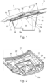
- Figure 1 shows a front portion of a vehicle 10 comprising a storage assembly 12.
- the storage assembly 12 forms a front luggage compartment 14 which can also be called a frunk. It is understood that this is just an example.
- the storage assembly 12 could as well form a rear luggage compartment of the vehicle 10.
- the storage assembly 12 comprises a storage receptacle 16 and a lid 18 being configured for moving between a closing position in which it closes the storage receptacle 16 and an open position, in which it opens the storage receptacle 16 such that it is accessible for a user.
- the storage receptacle 16 is cup-shaped.
- the lid 18 is formed by a portion of a hood 20 of the vehicle 10. This means that the lid 18 forms an integral structure with the hood 20. In a case in which the storage assembly 12 forms a rear luggage compartment, the lid 18 may be formed by a portion of trunk deck of the vehicle 10.
- the storage assembly is provided with a sealing arrangement 22 which is positioned at a rim 24 of the storage receptacle 16 or at the lid 18.
- the sealing arrangement 22 is arranged such that in the closing position of the lid 18 which is represented in Figure 1 , the sealing arrangement 22 is compressed between the storage receptacle 16 and the lid 18.
- the storage assembly 12 also comprises a closing facilitation mechanism which is generally designated with reference sign 26.
- the storage facilitation mechanism is configured for reducing a force for bringing the lid 18 into the closing position.
- the closing facilitation mechanism 26 comprises a deformable element 28 which is positioned at an inner surface 18a of the lid 18.
- the deformable element 28 is made from a rubber material and is elastically deformable.
- the deformable element 28 is generally dome-shaped when it assumes a first position P1. In this position, the dome-shape points towards the storage volume 30.
- a height H of the dome-shape is very small when being compared to a length L of a base surface of the deformable element 28.
- the deformable element 28 is also plate-shaped.
- the deformable element 28 is also configured for assuming a second position P2 in which it is also dome-shaped. However, in the second position P2, the dome-shape points away from the storage volume 30.
- the deformable element 28 is pre-tensioned towards the first position P1.
- the dome shape points towards the storage volume 30.
- the deformable element 28 is mounted to the lid 18 by means of a frame 32.
- the frame 32 is made from plastics material.
- the lid 18 of the storage assembly 12 may be closed using a method for closing a lid of a storage assembly of a vehicle.
- the method comprises compressing the sealing arrangement 22 by moving the lid 18 towards the rim 24 of the storage receptacle 16 (cf. Figure 4 ). This happens if the lid 18 is moved towards its closing position.
- the lid 18 and the sealing arrangement 22 are in sealing contact such that air being located inside the storage volume 30 is not able to flow into the exterior of the storage assembly 12 and vice versa.
- the deformable element 28 is switched from its first position P1 to its second positon P2.
- Compensating the reduction of the storage volume 30 leads to a reduction of a force resulting from a compression of the air being trapped in the storage volume 30 when the lid 18 is further moved into its closing position. This force acts against the closing of the lid 18.
- the lid 18 can be closed using a comparatively low force only.
- the deformable element 28 may return into its original shape, i.e. the first position P1 if a sufficient volume of gas has been removed. Then the closing facilitation mechanism 26 is ready for use again.
- the deformable element 28 may return to its first position if the lid 18 is opened. Also in this situation, the closing facilitation mechanism 26 becomes ready for use again.
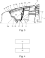
- Figure 3 shows a front portion of a vehicle 10 comprising a storage assembly 12 according to a second example.
- the second example differs from the first example in that the deformable element 28 forms a portion of a wall 34 of the storage receptacle 16.
- the deformable element 28 is mounted to the storage receptacle 16 by means of a frame 32. It is noted that this is just an example. Of course, the deformable element 28 can also be a part of the wall 34 itself or a part of a base of the storage receptacle 16.
- the deformable element 28 is shaped as the deformable element 28 of the first example. It is also configured for switching between a first position P1 and a second position P2.
Landscapes
- Engineering & Computer Science (AREA)
- Mechanical Engineering (AREA)
- Chemical & Material Sciences (AREA)
- Combustion & Propulsion (AREA)
- Transportation (AREA)
- Vehicle Step Arrangements And Article Storage (AREA)
- Superstructure Of Vehicle (AREA)
Abstract
Description
- The present disclosure relates to storage assembly for a vehicle.
- Moreover, the present disclosure is directed to a vehicle having such a storage assembly.
- Additionally, the disclosure relates to a method for closing a lid of a storage assembly of a vehicle.
- The storage assembly may form a front luggage compartment of the vehicle. Such a luggage compartment may be called a frunk. Also, the storage assembly may form a rear luggage compartment of the vehicle. Such a luggage compartment may be called a trunk. Of course, the storage assembly may also form any other type of luggage compartment, e.g. a side luggage compartment of a bus.
- Especially if the storage assembly and the luggage compartment formed therewith is accessible from an exterior, care has to be taken that the storage assembly is reliably sealed when closed. In doing so, water, humidity, dirt or other undesired substances are stopped from entering a storage volume of the storage assembly. Of course, the storage assembly shall also be simple and comfortable in use, i.e. the handling and manipulation of the storage assembly shall require comparatively low forces. Consequently, a human user can handle and manipulate the storage assembly with comparatively low effort.
- It has been found that a certain conflict of objectives exists between the tight and reliable sealing and the comfortable use of such a storage compartment.
- Consequently, the problem to be solved by the present disclosure is to alleviate or solve this conflict of objectives.
- The problem is at least partially solved or alleviated by the subject matter of the independent claims of the present disclosure, wherein further examples are incorporated in the dependent claims.
- According to a first aspect, there is provided a storage assembly for a vehicle. The SE:TOP
storage assembly comprises a storage receptacle. Moreover, the storage assembly comprises a lid being configured for moving between a closing position in which it closes the storage receptacle and an open position. Additionally, the storage assembly comprises a sealing arrangement being positioned at the storage receptacle or at the lid such that in the closing position of the lid, the sealing arrangement seals the storage receptacle with respect to the lid. Furthermore, the storage assembly comprises a closing facilitation mechanism being configured for reducing a force for bringing the lid into the closing position from the open position. In the open position the lid opens the storage receptacle such that a storage volume can be accessed from outside the storage assembly. - In an example, the receptacle may be cup-shaped. A cup-shaped receptacle is to be understood as a receptacle forming a storage volume, wherein the receptacle delimits the storage volume on all but one sides. In other words, the storage volume is accessible or open on one side only. The storage volume being formed by the cup-shaped receptacle and the cup-shaped receptacle itself can have any form. In an example, the storage volume may be generally block-shaped or generally cylinder-shaped or have any other regular or irregular form. An alternative term for cup-shaped is bowl-shaped.
- The finding underlying the present disclosure relates to the fact that when closing the lid of such a storage assembly, shortly before reaching the closing position, the lid already needs to contact the sealing arrangement. Otherwise, the sealing arrangement cannot be compressed and provide the desired sealing effect. In this situation, air is trapped inside a storage volume of the storage assembly being delimited by the storage receptacle and the lid. In order to finally reach the closing position, the sealing arrangement and the air being trapped in the storage volume need to be compressed. Both the sealing arrangement and the air form a spring acting against the closing of the lid. In this context, the trapped air leads to an over-pressure inside the storage volume. Thus, a comparatively high force needs to be applied to the lid in order to bring it into the closing position. This force needs to compensate the spring effects of the sealing arrangement and the trapped air cumulatively.
- The idea underlying the present disclosure is, thus, to provide a closing facilitation mechanism which is configured for reducing a force for bringing the lid into the closing position. As a consequence thereof, a user of the storage assembly only needs to apply a reduced force for closing the lid. This renders the manipulation comfortable and simple. A further advantage of such a closing facilitation mechanism is that a risk for deforming or damaging the lid is substantially reduced. It is obvious that the force for bringing the lid into the closing position needs to be applied to a certain point, line or area of the lid. The higher the force, the higher is the risk to damage or deform this area. This is especially the case if the lid is formed by a portion of a hood of a vehicle or by a portion of a trunk deck of a vehicle.
- The closing facilitation mechanism of the storage assembly of the present disclosure may also be designated a closing assistance mechanism.
- In an example, the sealing arrangement may be positioned at a rim of the storage receptacle. Alternatively, the sealing arrangement may be located at an interior of the storage receptacle.
- In an example, the storage assembly may form a frunk. In another example, the storage assembly may form a trunk. In a further example, the storage assembly may form a side luggage compartment.
- In an example, the lid may be plate-shaped.
- In an example, the closing facilitation mechanism may comprise a deformable element forming a portion of a wall of the storage receptacle or being positioned at an inner surface of the lid, such that the deformable element delimits a storage volume. It is noted that the deformable element delimits the storage volume in both alternatives. Due to its deformability and its position, the deformable element is able to selectively increase the storage volume. Thereby, a force resulting from the compression of the trapped air and acting against the lid being moved towards the closing position can be compensated fully or partially. As has been explained above, the trapped air forms a spring. When bringing the lid into the closing position while the sealing arrangement already contacts the lid, this spring is compressed from one side. In this situation, the deformable element can be deformed such that it increases the storage volume and the spring formed by the trapped air is less compressed or not at all.
- In an example, the deformable element is mounted to the storage receptacle or the lid by means of a frame. Consequently, the deformable element is reliably mounted to the storage receptacle or the lid. Additionally, the frame may keep the deformable element in form and/or in a position such that it can deform as desired.
- In an example, the frame may be additionally configured for holding the sealing arrangement. This allows for a compact design of the storage assembly.
- In an example, the frame comprises a plastics material. Such a frame may be mechanically stable and robust while at the same time being light-weight.
- In an example, the deformable element may be configured to take a first position, in which the deformable element is either flat or bulges towards the storage volume, and a second position, in which the deformable element bulges away from the storage volume. Consequently, if the deformable element is in the first position, the storage volume is smaller than in a situation in which the deformable element is in the second position. In the context of the present disclosure, the deformable element takes the first position when the lid is in its open position and when the lid is being closed, but does not yet contact the sealing arrangement and/or the storage receptacle. Thus, the deformable element is in the first position if air is able to travel between the storage volume and an exterior of the storage assembly. The deformable element transfers or transitions to the second position if the lid is in a position relative to the sealing arrangement and/or the storage receptacle in which air cannot transfer between the storage volume and the exterior and if the lid is moved towards its closing position. The same applies if the transfer of air between the storage volume and the exterior thereof cannot be performed fast enough.
- In an example, the first and second positions of the deformable element are predefined positions. Moreover, the deformable element may be configured such that it can either be in the first position or in the second position. Such a deformable element may be designated a bistable element.
- In an example, the deformable element may be dome-shaped in the first position, the dome-shape pointing towards the storage volume. Alternatively or additionally, the deformable element may be dome-shaped in the second position, the dome-shape pointing away from the storage volume. Thus, the deformable element may be generally dome shaped, wherein it is able to invert its shape. Thus, the storage volume can be selectively increased with high reliability. Moreover, the magnitude of the volume increase is well-defined. Consequently, closing of the lid is facilitated in a simple and reliable manner.
- In an example, the deformable element is pre-tensioned towards the first position. This has the effect that the deformable element can come back to the first position when being outside the first position, e.g. in the second position. A further condition for coming back to the first position is of course that a force resulting from the compression of trapped air has been reduced to a predefined extent or eliminated. The closing facilitation mechanism is thus reversible.
- In an example the pre-tensioning is achieved by pre-forming the deformable element in the first position.
- The pre-tensioned deformable element is very useful in situations in which in a closing position of the lid, trapped air is able to slowly leak, i.e. leave the storage volume. Thus, the deformable element can return to the first position while the storage assembly is closed. Subsequently, if the storage assembly is opened and about to be closed again, the closing facilitation mechanism is operational again.
- In an example, the deformable element comprises at least one of a plastics material, a rubber material and a fabric material. Using such a material the deformable element may be efficiently manufactured. Furthermore, these materials provide the deformation properties in a simple and reliable manner. It is understood that also other materials being able to provide deformation properties can be used. Consequently, the closing of the lid is facilitated in a simple and reliable manner.
- In an example, the deformable element is elastically deformable. In such a configuration, the deformation may only require a comparatively low force and therefore compensate to a high extent the force resulting from trapped air in the storage volume. Moreover, such a deformable element is reliably operational during a comparatively long lifetime.
- In an example, the deformable element may be plate-shaped. Thus it can be integrated into the storage assembly in a simple manner. Moreover, it only requires a comparatively small space.
- It is noted that also deformable elements being dome-shaped may be designated plate-shaped if a height of the dome is small compared to the dimensions of a base surface of the dome.
- In an example, the lid is formed by a portion of a hood of a vehicle or a portion of a trunk deck of a vehicle. The lid is, thus, realized in a space-saving manner.
- According to a second aspect there is provided a vehicle comprising a storage assembly according to the present disclosure. The storage assembly may form a front luggage compartment and the lid may be formed by at least a portion of a hood of the vehicle. Alternatively, the storage assembly may form a rear luggage compartment and the lid may be formed by at least a portion of trunk deck of the vehicle. The vehicle is for example a sedan car or a roadster. In such vehicles, a user of the storage assembly only needs to apply a comparatively low force for closing the lid. This renders the manipulation comfortable and simple. Moreover, a risk for deforming or damaging the lid is substantially reduced. Additionally, the storage volume is reliably sealed with respect to its exterior.
- According to a third aspect there is provided a method for closing a lid of a storage assembly of a vehicle. The lid is configured for moving between a closing position and an open position. In the closing position, the lid closes a storage receptacle via a sealing arrangement being interposed between the storage receptacle and the lid. The method comprises:
- compressing the sealing arrangement by moving the lid towards the storage receptacle, thereby reducing a storage volume of the storage assembly, and
- compensating the reduction of the storage volume by deforming at least a portion of a wall of the storage receptacle or by deforming at least a portion of an inner surface of the lid.
- As has already been explained in connection with the storage assembly according to the disclosure, the compression of the sealing arrangement leads to a compression of air being trapped in the storage volume of the storage assembly. A force acting against the closing of the lid results from these circumstances. By compensating the reduction of the storage volume, the magnitude of this force is reduced, i.e. fully or partially compensated. It is noted that the deformation occurs while the sealing arrangement already provides a sealing effect. Consequently, the storage assembly is reliably sealed. At the same time the closing of the lid is comfortable and simple. Furthermore, a risk for deforming or damaging the lid is substantially reduced.
- In an example, the lid is locked once it reaches the closing position.
- In an example, compensating the reduction of the storage volume comprises switching the portion of the wall of the storage receptacle or the portion of the inner surface of the lid from a predefined first position into a predefined second position. This results in a predefined and reliable compensation of the volume reduction.
- In an example, the method may comprise removing a volume of gas from the storage volume of the storage assembly, and returning the portion of the wall of the storage receptacle or the portion of the inner surface of the lid to the respective original shape. Consequently, the portion is ready for being used for compensating a volume reduction again. It is noted that the removing of a gas volume may happen passively, e.g. in that a volume of gas leaks from the storage volume to the exterior.
- It should be noted that the above examples may be combined with each other irrespective of the aspect involved.
- These and other aspects of the present disclosure will become apparent from and elucidated with reference to the examples described hereinafter.
- Examples of the disclosure will be described in the following with reference to the following drawings.
- Fig. 1
- shows relevant parts of a front portion of a vehicle according to the present disclosure comprising a storage assembly according to a first example of the present disclosure which can be operated by a method according to the present disclosure,
- Fig. 2
- shows a hood of the vehicle of
Figure 1 comprising a lid of the storage assembly ofFigure 1 , - Fig. 3
- shows relevant parts of a front portion of a vehicle according to the present disclosure comprising a storage assembly according to a second example of the present disclosure which can be operated by a method according to the present disclosure, and
- Fig. 4
- shows steps of a method for closing a lid of a storage assembly of a vehicle according to the present disclosure.
- The figures are merely schematic representations and serve only to illustrate examples of the disclosure. Identical or equivalent elements are in principle provided with the same reference signs.
-
Figure 1 shows a front portion of avehicle 10 comprising astorage assembly 12. - In the example shown in
Figure 1 , thestorage assembly 12 forms afront luggage compartment 14 which can also be called a frunk. It is understood that this is just an example. Thestorage assembly 12 could as well form a rear luggage compartment of thevehicle 10. - The
storage assembly 12 comprises astorage receptacle 16 and alid 18 being configured for moving between a closing position in which it closes thestorage receptacle 16 and an open position, in which it opens thestorage receptacle 16 such that it is accessible for a user. - In the example shown in the Figures, the
storage receptacle 16 is cup-shaped. - Since in the present example, the
storage assembly 12 forms frunk, thelid 18 is formed by a portion of ahood 20 of thevehicle 10. This means that thelid 18 forms an integral structure with thehood 20. In a case in which thestorage assembly 12 forms a rear luggage compartment, thelid 18 may be formed by a portion of trunk deck of thevehicle 10. - The storage assembly is provided with a sealing
arrangement 22 which is positioned at arim 24 of thestorage receptacle 16 or at thelid 18. - In any case, the sealing
arrangement 22 is arranged such that in the closing position of thelid 18 which is represented inFigure 1 , the sealingarrangement 22 is compressed between thestorage receptacle 16 and thelid 18. - The
storage assembly 12 also comprises a closing facilitation mechanism which is generally designated withreference sign 26. The storage facilitation mechanism is configured for reducing a force for bringing thelid 18 into the closing position. - The
closing facilitation mechanism 26 comprises adeformable element 28 which is positioned at aninner surface 18a of thelid 18. - In this position, the
deformable element 28 together with the remaining portions of the lid and thereceptacle 16 delimits astorage volume 30 of thestorage assembly 12. - In the present example, the
deformable element 28 is made from a rubber material and is elastically deformable. - Moreover, the
deformable element 28 is generally dome-shaped when it assumes a first position P1. In this position, the dome-shape points towards thestorage volume 30. - It is noted that a height H of the dome-shape is very small when being compared to a length L of a base surface of the
deformable element 28. - Thus, the
deformable element 28 is also plate-shaped. - The
deformable element 28 is also configured for assuming a second position P2 in which it is also dome-shaped. However, in the second position P2, the dome-shape points away from thestorage volume 30. - The
deformable element 28 is pre-tensioned towards the first position P1. Thus, in the absence of external forces, the dome shape points towards thestorage volume 30. - In the present example, the
deformable element 28 is mounted to thelid 18 by means of aframe 32. Theframe 32 is made from plastics material. - The
lid 18 of thestorage assembly 12 may be closed using a method for closing a lid of a storage assembly of a vehicle. - In a first step S1, the method comprises compressing the sealing
arrangement 22 by moving thelid 18 towards therim 24 of the storage receptacle 16 (cf.Figure 4 ). This happens if thelid 18 is moved towards its closing position. - In this situation, the
lid 18 and the sealingarrangement 22 are in sealing contact such that air being located inside thestorage volume 30 is not able to flow into the exterior of thestorage assembly 12 and vice versa. - Thus, when further moving the
lid 18 towards its closing position, thestorage volume 30 of thestorage assembly 12 is reduced. - In a second step S2 of the method, this reduction of the
storage volume 30 is compensated. - To this end, the
deformable element 28 is switched from its first position P1 to its second positon P2. - Compensating the reduction of the
storage volume 30 leads to a reduction of a force resulting from a compression of the air being trapped in thestorage volume 30 when thelid 18 is further moved into its closing position. This force acts against the closing of thelid 18. - Consequently, the
lid 18 can be closed using a comparatively low force only. Thelid 18, thus, reaches its closing position. - While the
lid 18 is in its closing position, a volume of gas may be removed from thestorage volume 30 of thestorage assembly 12. Due to leakage, this may happen without any action being necessary just by waiting. - Caused by the above-described pre-tensioning of the
deformable element 28 into the first position P1, thedeformable element 28 may return into its original shape, i.e. the first position P1 if a sufficient volume of gas has been removed. Then the closingfacilitation mechanism 26 is ready for use again. - Alternatively, the
deformable element 28 may return to its first position if thelid 18 is opened. Also in this situation, theclosing facilitation mechanism 26 becomes ready for use again. -
Figure 3 shows a front portion of avehicle 10 comprising astorage assembly 12 according to a second example. - In the following, only the differences between the second example and the first example shown in
Figure 1 and 2 will be explained. For the remaining aspects, reference is made to the above explanations. - The second example differs from the first example in that the
deformable element 28 forms a portion of awall 34 of thestorage receptacle 16. - Also in this example, the
deformable element 28 is mounted to thestorage receptacle 16 by means of aframe 32. It is noted that this is just an example. Of course, thedeformable element 28 can also be a part of thewall 34 itself or a part of a base of thestorage receptacle 16. - The
deformable element 28 is shaped as thedeformable element 28 of the first example. It is also configured for switching between a first position P1 and a second position P2. - Thus, also the method for closing a
lid 18 of astorage assembly 12 of avehicle 10 as explained above can be applied in connection with the second example (cf.Figure 4 ). - Other variations to the disclosed examples can be understood and effected by those skilled in the art in practicing the claimed disclosure, from the study of the drawings, the disclosure, and the appended claims. In the claims the word "comprising" does not exclude other elements or steps and the indefinite article "a" or "an" does not exclude a plurality. The mere fact that certain measures are recited in mutually different dependent claims does not indicate that a combination of these measures cannot be used to advantage. Any reference signs in the claims should not be construed as limiting the scope of the claims.
-
- 10
- vehicle
- 12
- storage assembly
- 14
- front luggage compartment
- 16
- storage receptacle
- 18
- lid
- 18a
- inner surface
- 20
- hood
- 22
- sealing arrangement
- 24
- rim
- 26
- closing facilitation mechanism
- 28
- deformable element
- 30
- storage volume
- 32
- frame
- 34
- wall
- H
- height
- L
- length
- P1
- first position
- P2
- second position
- S1
- step
- S2
- step
Claims (15)
- A storage assembly (12) for a vehicle (10), comprisinga storage receptacle (16),a lid (18) being configured for moving between a closing position in which it closes the storage receptacle (16) and an open position,a sealing arrangement (22) being positioned at the storage receptacle (16) or at the lid (18) such that in the closing position of the lid (18), the sealing arrangement (22) seals the storage receptacle (16) with respect to the lid (18), anda closing facilitation mechanism (26) being configured for reducing a force for bringing the lid (18) into the closing position from the open position.
- The storage assembly (12) according to claim 1, wherein the closing facilitation mechanism (26) comprises a deformable element (28) forming a portion of a wall (34) of the storage receptacle (16) or being positioned at an inner surface of the lid (18), such that the deformable element (28) delimits a storage volume (30).
- The storage assembly (12) according to claim 2, wherein the deformable element (28) is mounted to the storage receptacle (16) or the lid (18) by means of a frame (32).
- The storage assembly (12) according to claim 3, wherein the frame (32) comprises a plastics material.
- The storage assembly (12) according to any one of claims 2 to 4, wherein the deformable element (28) is configured to take a first position (PI), in which the deformable element (28) is either flat or bulges towards the storage volume (30), and a second position (P2), in which the deformable element (28) bulges away from the storage volume (30).
- The storage assembly (12) according to claim 5, wherein the deformable element (28) is dome-shaped in the first position (PI), the dome-shape pointing towards the storage volume (30), and/or wherein the deformable element (28) is dome-shaped in the second position (P2), the dome-shape pointing away from the storage volume (30).
- The storage element (12) according to claim 5 or 6, wherein the deformable element (28) is pre-tensioned towards the first position (P1).
- The storage element (12) according to any one of claims 2 to 7, wherein the deformable element (28) comprises at least one of a plastics material, a rubber material and a fabric material.
- The storage assembly (12) according to any one of claims 2 to 8, wherein the deformable element (28) is elastically deformable.
- The storage assembly (12) according to any one of claims 2 to 9, wherein the deformable element (28) is plate-shaped.
- The storage assembly (12) according to any one of the preceding claims, wherein the lid (18) is formed by a portion of a hood (20) of a vehicle (10) or a portion of a trunk deck of the vehicle (10).
- A vehicle (10) comprising a storage assembly (12) according to any one of the preceding claims, wherein the storage assembly (12) forms a front luggage compartment (14) and the lid (18) is formed by at least a portion of a hood (20) of the vehicle (10) or
wherein the storage assembly (12) forms a rear luggage compartment and the lid (18) is formed by at least a portion of a trunk deck of the vehicle (10). - A method for closing a lid (18) of a storage assembly (12) of a vehicle (10), the lid (18) being configured for moving between a closing position and an open position, wherein in the closing position the lid (18) closes a storage receptacle (16) via a sealing arrangement (22) being interposed between the storage receptacle (16) and the lid (18), comprising:- compressing the sealing arrangement (22) by moving the lid (18) towards the storage receptacle (16), thereby reducing a storage volume (30) of the storage assembly (12), and- compensating the reduction of the storage volume (30) by deforming at least a portion of a wall (34) of the storage receptacle (16) or by deforming at least a portion of an inner surface of the lid (18).
- The method according to claim 13, wherein compensating the reduction of the storage volume (30) comprises switching the portion of the wall (34) of the storage receptacle (16) or the portion of the inner surface of the lid (18) from a predefined first position (P1) into a predefined second position (P2).
- The method according to claim 13 or 14, comprising- removing a volume of gas from the storage volume (30) of the storage assembly (12), and- returning the portion of the wall (34) of the storage receptacle (16) or the portion of the inner surface of the lid (18) to the respective original shape.
Priority Applications (3)
| Application Number | Priority Date | Filing Date | Title |
|---|---|---|---|
| EP21216674.8A EP4201746B1 (en) | 2021-12-21 | 2021-12-21 | Storage assembly for a vehicle, vehicle, and method for closing a lid of a storage assembly |
| US18/083,759 US20230192001A1 (en) | 2021-12-21 | 2022-12-19 | Storage assembly for a vehicle, vehicle, and method for closing a lid of a storage assembly |
| CN202211641921.7A CN116279836A (en) | 2021-12-21 | 2022-12-20 | Storage assembly for a vehicle, vehicle and method for closing a lid of a storage assembly |
Applications Claiming Priority (1)
| Application Number | Priority Date | Filing Date | Title |
|---|---|---|---|
| EP21216674.8A EP4201746B1 (en) | 2021-12-21 | 2021-12-21 | Storage assembly for a vehicle, vehicle, and method for closing a lid of a storage assembly |
Publications (2)
| Publication Number | Publication Date |
|---|---|
| EP4201746A1 true EP4201746A1 (en) | 2023-06-28 |
| EP4201746B1 EP4201746B1 (en) | 2024-02-07 |
Family
ID=79019093
Family Applications (1)
| Application Number | Title | Priority Date | Filing Date |
|---|---|---|---|
| EP21216674.8A Active EP4201746B1 (en) | 2021-12-21 | 2021-12-21 | Storage assembly for a vehicle, vehicle, and method for closing a lid of a storage assembly |
Country Status (3)
| Country | Link |
|---|---|
| US (1) | US20230192001A1 (en) |
| EP (1) | EP4201746B1 (en) |
| CN (1) | CN116279836A (en) |
Families Citing this family (4)
| Publication number | Priority date | Publication date | Assignee | Title |
|---|---|---|---|---|
| DE102018206316B4 (en) * | 2018-04-24 | 2021-06-24 | Audi Ag | Sealed storage compartment for a motor vehicle and motor vehicle with such a storage compartment |
| JP6705579B1 (en) * | 2019-01-10 | 2020-06-03 | 日本製鉄株式会社 | Car hood |
| JPWO2020145199A1 (en) * | 2019-01-10 | 2021-10-28 | 日本製鉄株式会社 | Car hood |
| JP7436913B2 (en) * | 2020-03-30 | 2024-02-22 | 日本製鉄株式会社 | automotive hood |
Citations (2)
| Publication number | Priority date | Publication date | Assignee | Title |
|---|---|---|---|---|
| DE102019108937A1 (en) * | 2019-04-05 | 2020-10-08 | Dr. Ing. H.C. F. Porsche Aktiengesellschaft | Cover hood for a vehicle compartment |
| DE102019125586A1 (en) * | 2019-09-24 | 2021-03-25 | Dr. Ing. H.C. F. Porsche Aktiengesellschaft | Motor vehicle |
-
2021
- 2021-12-21 EP EP21216674.8A patent/EP4201746B1/en active Active
-
2022
- 2022-12-19 US US18/083,759 patent/US20230192001A1/en active Pending
- 2022-12-20 CN CN202211641921.7A patent/CN116279836A/en active Pending
Patent Citations (2)
| Publication number | Priority date | Publication date | Assignee | Title |
|---|---|---|---|---|
| DE102019108937A1 (en) * | 2019-04-05 | 2020-10-08 | Dr. Ing. H.C. F. Porsche Aktiengesellschaft | Cover hood for a vehicle compartment |
| DE102019125586A1 (en) * | 2019-09-24 | 2021-03-25 | Dr. Ing. H.C. F. Porsche Aktiengesellschaft | Motor vehicle |
Also Published As
| Publication number | Publication date |
|---|---|
| US20230192001A1 (en) | 2023-06-22 |
| EP4201746B1 (en) | 2024-02-07 |
| CN116279836A (en) | 2023-06-23 |
Similar Documents
| Publication | Publication Date | Title |
|---|---|---|
| EP4201746A1 (en) | Storage assembly for a vehicle, vehicle, and method for closing a lid of a storage assembly | |
| CN109383258A (en) | Method for manufacturing electrically driven vehicle | |
| US10214159B1 (en) | Engine compartment soundproof cover device of cab-over truck | |
| US6846034B1 (en) | Vehicular weather strip | |
| US12012787B2 (en) | Tailgate switching device | |
| CN214822542U (en) | Expansion structure of pickup truck cover | |
| US7128362B2 (en) | Stowage system for a retractable roof of a convertible vehicle | |
| KR101796246B1 (en) | Door opening and shutting structure of wingbody truck | |
| US11149866B2 (en) | Discharge valve | |
| JPH0511243U (en) | Switch device | |
| EP4365037A1 (en) | Storage assembly and hood assembly for a vehicle, vehicle and method for operating a hood assembly | |
| JP2004063773A (en) | Relief valve for capacitor and capacitor equipped therewith | |
| CN211623057U (en) | Unmanned delivery car | |
| JPH023527A (en) | Weather strip for automobile | |
| JPH10335406A (en) | Door opening mechanism | |
| CN209650132U (en) | A kind of interior laterally turning-over device of bulk grain transportation semi-trailer | |
| CN218815830U (en) | Overturning hovering structure and automobile spare tire cover plate | |
| CN217944868U (en) | Split skylight and car | |
| JPH10308427A (en) | Door opening and closing mechanism | |
| EP4212370A1 (en) | Vehicle tailgate assembly and vehicle | |
| CN213139982U (en) | Folding type container rain-proof water door | |
| CN214689793U (en) | Lift carriage roof seal structure | |
| CN215042478U (en) | Door panel, automotive interior assembly, automobile and storage bag | |
| CN211000878U (en) | Special-purpose vehicle electric skylight | |
| CN211969407U (en) | Automobile vacuum degree control switch, automobile brake power assisting system and automobile |
Legal Events
| Date | Code | Title | Description |
|---|---|---|---|
| PUAI | Public reference made under article 153(3) epc to a published international application that has entered the european phase |
Free format text: ORIGINAL CODE: 0009012 |
|
| STAA | Information on the status of an ep patent application or granted ep patent |
Free format text: STATUS: REQUEST FOR EXAMINATION WAS MADE |
|
| REG | Reference to a national code |
Ref country code: DE Ref legal event code: R079 Ref document number: 602021009205 Country of ref document: DE Free format text: PREVIOUS MAIN CLASS: B60R0005000000 Ipc: B62D0025120000 Ref country code: DE Ref legal event code: R079 Free format text: PREVIOUS MAIN CLASS: B60R0005000000 Ipc: B62D0025120000 |
|
| 17P | Request for examination filed |
Effective date: 20220718 |
|
| AK | Designated contracting states |
Kind code of ref document: A1 Designated state(s): AL AT BE BG CH CY CZ DE DK EE ES FI FR GB GR HR HU IE IS IT LI LT LU LV MC MK MT NL NO PL PT RO RS SE SI SK SM TR |
|
| GRAP | Despatch of communication of intention to grant a patent |
Free format text: ORIGINAL CODE: EPIDOSNIGR1 |
|
| STAA | Information on the status of an ep patent application or granted ep patent |
Free format text: STATUS: GRANT OF PATENT IS INTENDED |
|
| RIC1 | Information provided on ipc code assigned before grant |
Ipc: B62D 25/10 20060101ALI20230622BHEP Ipc: B60R 5/00 20060101ALI20230622BHEP Ipc: B62D 25/08 20060101ALI20230622BHEP Ipc: B62D 25/12 20060101AFI20230622BHEP |
|
| INTG | Intention to grant announced |
Effective date: 20230707 |
|
| GRAS | Grant fee paid |
Free format text: ORIGINAL CODE: EPIDOSNIGR3 |
|
| GRAA | (expected) grant |
Free format text: ORIGINAL CODE: 0009210 |
|
| STAA | Information on the status of an ep patent application or granted ep patent |
Free format text: STATUS: THE PATENT HAS BEEN GRANTED |
|
| AK | Designated contracting states |
Kind code of ref document: B1 Designated state(s): AL AT BE BG CH CY CZ DE DK EE ES FI FR GB GR HR HU IE IS IT LI LT LU LV MC MK MT NL NO PL PT RO RS SE SI SK SM TR |
|
| REG | Reference to a national code |
Ref country code: GB Ref legal event code: FG4D |
|
| REG | Reference to a national code |
Ref country code: CH Ref legal event code: EP |
|
| P01 | Opt-out of the competence of the unified patent court (upc) registered |
Effective date: 20240115 |
|
| REG | Reference to a national code |
Ref country code: IE Ref legal event code: FG4D |
|
| REG | Reference to a national code |
Ref country code: DE Ref legal event code: R096 Ref document number: 602021009205 Country of ref document: DE |
|
| REG | Reference to a national code |
Ref country code: LT Ref legal event code: MG9D |
|
| REG | Reference to a national code |
Ref country code: NL Ref legal event code: MP Effective date: 20240207 |
|
| PG25 | Lapsed in a contracting state [announced via postgrant information from national office to epo] |
Ref country code: IS Free format text: LAPSE BECAUSE OF FAILURE TO SUBMIT A TRANSLATION OF THE DESCRIPTION OR TO PAY THE FEE WITHIN THE PRESCRIBED TIME-LIMIT Effective date: 20240607 |
|
| PG25 | Lapsed in a contracting state [announced via postgrant information from national office to epo] |
Ref country code: LT Free format text: LAPSE BECAUSE OF FAILURE TO SUBMIT A TRANSLATION OF THE DESCRIPTION OR TO PAY THE FEE WITHIN THE PRESCRIBED TIME-LIMIT Effective date: 20240207 |
|
| PG25 | Lapsed in a contracting state [announced via postgrant information from national office to epo] |
Ref country code: GR Free format text: LAPSE BECAUSE OF FAILURE TO SUBMIT A TRANSLATION OF THE DESCRIPTION OR TO PAY THE FEE WITHIN THE PRESCRIBED TIME-LIMIT Effective date: 20240508 |
|
| REG | Reference to a national code |
Ref country code: AT Ref legal event code: MK05 Ref document number: 1655205 Country of ref document: AT Kind code of ref document: T Effective date: 20240207 |
|
| PG25 | Lapsed in a contracting state [announced via postgrant information from national office to epo] |
Ref country code: HR Free format text: LAPSE BECAUSE OF FAILURE TO SUBMIT A TRANSLATION OF THE DESCRIPTION OR TO PAY THE FEE WITHIN THE PRESCRIBED TIME-LIMIT Effective date: 20240207 Ref country code: RS Free format text: LAPSE BECAUSE OF FAILURE TO SUBMIT A TRANSLATION OF THE DESCRIPTION OR TO PAY THE FEE WITHIN THE PRESCRIBED TIME-LIMIT Effective date: 20240507 Ref country code: NL Free format text: LAPSE BECAUSE OF FAILURE TO SUBMIT A TRANSLATION OF THE DESCRIPTION OR TO PAY THE FEE WITHIN THE PRESCRIBED TIME-LIMIT Effective date: 20240207 |
|
| PG25 | Lapsed in a contracting state [announced via postgrant information from national office to epo] |
Ref country code: ES Free format text: LAPSE BECAUSE OF FAILURE TO SUBMIT A TRANSLATION OF THE DESCRIPTION OR TO PAY THE FEE WITHIN THE PRESCRIBED TIME-LIMIT Effective date: 20240207 |
|
| PG25 | Lapsed in a contracting state [announced via postgrant information from national office to epo] |
Ref country code: AT Free format text: LAPSE BECAUSE OF FAILURE TO SUBMIT A TRANSLATION OF THE DESCRIPTION OR TO PAY THE FEE WITHIN THE PRESCRIBED TIME-LIMIT Effective date: 20240207 |
|
| PG25 | Lapsed in a contracting state [announced via postgrant information from national office to epo] |
Ref country code: RS Free format text: LAPSE BECAUSE OF FAILURE TO SUBMIT A TRANSLATION OF THE DESCRIPTION OR TO PAY THE FEE WITHIN THE PRESCRIBED TIME-LIMIT Effective date: 20240507 Ref country code: NO Free format text: LAPSE BECAUSE OF FAILURE TO SUBMIT A TRANSLATION OF THE DESCRIPTION OR TO PAY THE FEE WITHIN THE PRESCRIBED TIME-LIMIT Effective date: 20240507 Ref country code: NL Free format text: LAPSE BECAUSE OF FAILURE TO SUBMIT A TRANSLATION OF THE DESCRIPTION OR TO PAY THE FEE WITHIN THE PRESCRIBED TIME-LIMIT Effective date: 20240207 Ref country code: LT Free format text: LAPSE BECAUSE OF FAILURE TO SUBMIT A TRANSLATION OF THE DESCRIPTION OR TO PAY THE FEE WITHIN THE PRESCRIBED TIME-LIMIT Effective date: 20240207 Ref country code: IS Free format text: LAPSE BECAUSE OF FAILURE TO SUBMIT A TRANSLATION OF THE DESCRIPTION OR TO PAY THE FEE WITHIN THE PRESCRIBED TIME-LIMIT Effective date: 20240607 Ref country code: HR Free format text: LAPSE BECAUSE OF FAILURE TO SUBMIT A TRANSLATION OF THE DESCRIPTION OR TO PAY THE FEE WITHIN THE PRESCRIBED TIME-LIMIT Effective date: 20240207 Ref country code: GR Free format text: LAPSE BECAUSE OF FAILURE TO SUBMIT A TRANSLATION OF THE DESCRIPTION OR TO PAY THE FEE WITHIN THE PRESCRIBED TIME-LIMIT Effective date: 20240508 Ref country code: FI Free format text: LAPSE BECAUSE OF FAILURE TO SUBMIT A TRANSLATION OF THE DESCRIPTION OR TO PAY THE FEE WITHIN THE PRESCRIBED TIME-LIMIT Effective date: 20240207 Ref country code: ES Free format text: LAPSE BECAUSE OF FAILURE TO SUBMIT A TRANSLATION OF THE DESCRIPTION OR TO PAY THE FEE WITHIN THE PRESCRIBED TIME-LIMIT Effective date: 20240207 Ref country code: BG Free format text: LAPSE BECAUSE OF FAILURE TO SUBMIT A TRANSLATION OF THE DESCRIPTION OR TO PAY THE FEE WITHIN THE PRESCRIBED TIME-LIMIT Effective date: 20240207 Ref country code: AT Free format text: LAPSE BECAUSE OF FAILURE TO SUBMIT A TRANSLATION OF THE DESCRIPTION OR TO PAY THE FEE WITHIN THE PRESCRIBED TIME-LIMIT Effective date: 20240207 |
|
| PG25 | Lapsed in a contracting state [announced via postgrant information from national office to epo] |
Ref country code: PT Free format text: LAPSE BECAUSE OF FAILURE TO SUBMIT A TRANSLATION OF THE DESCRIPTION OR TO PAY THE FEE WITHIN THE PRESCRIBED TIME-LIMIT Effective date: 20240607 Ref country code: PL Free format text: LAPSE BECAUSE OF FAILURE TO SUBMIT A TRANSLATION OF THE DESCRIPTION OR TO PAY THE FEE WITHIN THE PRESCRIBED TIME-LIMIT Effective date: 20240207 |
|
| PG25 | Lapsed in a contracting state [announced via postgrant information from national office to epo] |
Ref country code: SE Free format text: LAPSE BECAUSE OF FAILURE TO SUBMIT A TRANSLATION OF THE DESCRIPTION OR TO PAY THE FEE WITHIN THE PRESCRIBED TIME-LIMIT Effective date: 20240207 Ref country code: PT Free format text: LAPSE BECAUSE OF FAILURE TO SUBMIT A TRANSLATION OF THE DESCRIPTION OR TO PAY THE FEE WITHIN THE PRESCRIBED TIME-LIMIT Effective date: 20240607 Ref country code: PL Free format text: LAPSE BECAUSE OF FAILURE TO SUBMIT A TRANSLATION OF THE DESCRIPTION OR TO PAY THE FEE WITHIN THE PRESCRIBED TIME-LIMIT Effective date: 20240207 Ref country code: LV Free format text: LAPSE BECAUSE OF FAILURE TO SUBMIT A TRANSLATION OF THE DESCRIPTION OR TO PAY THE FEE WITHIN THE PRESCRIBED TIME-LIMIT Effective date: 20240207 |