EP4201736B1 - Sicherheitssitz - Google Patents
Sicherheitssitz Download PDFInfo
- Publication number
- EP4201736B1 EP4201736B1 EP21896260.3A EP21896260A EP4201736B1 EP 4201736 B1 EP4201736 B1 EP 4201736B1 EP 21896260 A EP21896260 A EP 21896260A EP 4201736 B1 EP4201736 B1 EP 4201736B1
- Authority
- EP
- European Patent Office
- Prior art keywords
- connecting base
- fixing
- base
- clamping
- seat
- Prior art date
- Legal status (The legal status is an assumption and is not a legal conclusion. Google has not performed a legal analysis and makes no representation as to the accuracy of the status listed.)
- Active
Links
Images


Classifications
-
- B—PERFORMING OPERATIONS; TRANSPORTING
- B60—VEHICLES IN GENERAL
- B60N—SEATS SPECIALLY ADAPTED FOR VEHICLES; VEHICLE PASSENGER ACCOMMODATION NOT OTHERWISE PROVIDED FOR
- B60N2/00—Seats specially adapted for vehicles; Arrangement or mounting of seats in vehicles
- B60N2/24—Seats specially adapted for vehicles; Arrangement or mounting of seats in vehicles for particular purposes or particular vehicles
- B60N2/26—Seats specially adapted for vehicles; Arrangement or mounting of seats in vehicles for particular purposes or particular vehicles for children
- B60N2/28—Seats readily mountable on, and dismountable from, existing seats or other parts of the vehicle
- B60N2/2869—Seats readily mountable on, and dismountable from, existing seats or other parts of the vehicle rotatable about a vertical axis
-
- B—PERFORMING OPERATIONS; TRANSPORTING
- B60—VEHICLES IN GENERAL
- B60N—SEATS SPECIALLY ADAPTED FOR VEHICLES; VEHICLE PASSENGER ACCOMMODATION NOT OTHERWISE PROVIDED FOR
- B60N2/00—Seats specially adapted for vehicles; Arrangement or mounting of seats in vehicles
- B60N2/24—Seats specially adapted for vehicles; Arrangement or mounting of seats in vehicles for particular purposes or particular vehicles
- B60N2/26—Seats specially adapted for vehicles; Arrangement or mounting of seats in vehicles for particular purposes or particular vehicles for children
- B60N2/28—Seats readily mountable on, and dismountable from, existing seats or other parts of the vehicle
- B60N2/2821—Seats readily mountable on, and dismountable from, existing seats or other parts of the vehicle having a seat and a base part
-
- B—PERFORMING OPERATIONS; TRANSPORTING
- B60—VEHICLES IN GENERAL
- B60N—SEATS SPECIALLY ADAPTED FOR VEHICLES; VEHICLE PASSENGER ACCOMMODATION NOT OTHERWISE PROVIDED FOR
- B60N2/00—Seats specially adapted for vehicles; Arrangement or mounting of seats in vehicles
- B60N2/24—Seats specially adapted for vehicles; Arrangement or mounting of seats in vehicles for particular purposes or particular vehicles
- B60N2/26—Seats specially adapted for vehicles; Arrangement or mounting of seats in vehicles for particular purposes or particular vehicles for children
- B60N2/28—Seats readily mountable on, and dismountable from, existing seats or other parts of the vehicle
- B60N2/2875—Seats readily mountable on, and dismountable from, existing seats or other parts of the vehicle inclinable, as a whole or partially
Definitions
- the present invention relates to the technical field of child seats, and in particular, to a safety seat.
- a safety seat as a seat tied to a vehicle seat is a vehicle accessory device having a binding protection function, and is a seat that is only for a child to sit in and can bind the child to ensure safety of the child in the case of a vehicle accident.
- CN109532586 shows a safety seat comprising: a seat structure and a base, wherein the seat structure and the base are rotatably connected, and the seat structure comprises a connecting base, an adjusting assembly and a seat body; the seat body is mounted on the connecting base, and the adjusting assembly is mounted on the seat body and is selectively connected to the connecting base; and when the adjusting assembly is disengaged from the connecting base, the seat body is capable of being disconnected from the connecting base and the base such that the rotation angle of the seat structure relative to the connecting base is adjusted and the pitch angle of the seat body relative to the connecting base is adjusted.
- An objective of the present invention is to provide a safety seat, which can adjust the pitch angle and the rotation angle of the safety seat simultaneously, and improve the comfort for a child during use.
- a safety seat comprising: a seat structure and a base, wherein the seat structure and the base are rotatably connected, and the seat structure comprises a connecting base, an adjusting assembly and a seat body; the seat body is mounted on the connecting base, and the adjusting assembly is mounted on the seat body and is selectively connected to the connecting base; and when the adjusting assembly is disengaged from the connecting base, the seat body can be disconnected from the connecting base and the base such that the rotation angle of the seat structure relative to the connecting base is adjusted and the pitch angle of the seat body relative to the connecting base is adjusted.
- the adjusting assembly comprises a connecting portion, a fixing member and an elastic member, wherein one end of the elastic member is connected to the connecting base, the other end thereof is connected to the fixing member, the fixing member is fixed to the connecting portion, the fixing member selectively matches the connecting base, the connecting portion is configured to drive the fixing member to move away from the connecting base under the action of an external force, so that the fixing member is disengaged from the connecting base, and the seat body can adjust the pitch angle of the seat body relative to the connecting base and the rotation angle of the seat structure relative to the base; and the elastic member drives the fixing member to move close to the connecting base when the external force is removed, so that the fixing member matches the connecting base, and the seat body is fixedly connected to the connecting base.
- the fixing member comprises a first fixing portion, a second fixing portion is arranged on the connecting base, and the first fixing portion selectively matches the second fixing portion; and when an external force is applied to the connecting portion, the first fixing portion is disengaged from the second fixing portion, and when the external force is removed, the first fixing portion matches the second fixing portion.
- the fixing member comprises a first guide portion
- the adjusting assembly further comprises a connecting housing
- the connecting housing is fixedly connected to the connecting base
- a second guide portion is arranged on the connecting housing
- the first guide portion matches the second guide portion
- the first guide portion slides in an extension direction of the second guide portion, so that the first fixing portion moves away from the second fixing portion, and is disengaged from the second fixing portion.
- the second guide portion is arranged obliquely.
- a fixing member is arranged on the connecting base, a clamping member is further arranged on the seat body, the fixing member is connected to the clamping member, and the clamping member is selectively fixed to the base; when the adjusting assembly is disengaged from the connecting base, the fixing member can drive the clamping member to move relative to the connecting base, so that the clamping member is disengaged from the base, and the seat structure is rotatable relative to the base, and adjusts the pitch angle of the seat body relative to the connecting base.
- the clamping member comprises a positioning portion and a clamping portion
- the base is further provided with a clamping groove
- the positioning portion matches the fixing member
- the positioning portion is fixedly connected to the clamping portion
- the fixing member can drive the clamping portion to move in a direction close to or away from the clamping groove by means of the positioning portion, so that the clamping portion matches or is disengaged from the clamping groove.
- the positioning portion comprises an elastic portion and an abutting portion, wherein one end of the elastic portion is connected to the clamping portion, the other end thereof is connected to the abutting portion, and the abutting portion matches the clamping member.
- the fixing member comprises a fixing plate and a plurality of stop portions spaced on the fixing plate, and a positioning groove is formed between two adjacent stop portions; when the clamping member abuts against the stop portions, the clamping member is disconnected from the connecting base; and when the clamping member matches the positioning groove, the clamping member matches the base.
- each of the stop portions has an obliquely arranged guide face, and the guide face extends to a bottom wall of the positioning groove.
- the safety seat comprises a seat structure and a base, wherein the seat structure and the base are rotatably connected, and the seat structure comprises a connecting base, an adjusting assembly and a seat body; the seat body is mounted on the connecting base, and the adjusting assembly is mounted on the seat body and is selectively connected to the connecting base; and when the adjusting assembly is disengaged from the connecting base, the seat body can be disconnected from the connecting base and the base such that the rotation angle of the seat structure relative to the connecting base is adjusted and the pitch angle of the seat body relative to the connecting base is adjusted.
- the rotation angle of the entire seat structure relative to the base can be adjusted and the pitch angle of the seat body relative to the connecting base can also be adjusted.
- the rotation angle and the pitch angle can be adjusted simultaneously in a single operation. The convenience of operation is improved and the comfort for a child during use is also improved.
- orientation or positional relationship indicated by the terms is based on the orientation or positional relationship shown in the accompanying diagrams, or is the orientation or positional relationship of usual placement of the product of the present invention when in use, which is only for convenience of the description of the present invention and the simplified description, rather than indicating or implying that the devices or elements specified necessarily have a specific orientation or are constructed and operated in a specific orientation, and therefore cannot be construed as limiting the present invention.
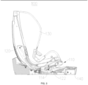
- this embodiment provides a safety seat 100.
- the safety seat 100 according to this embodiment can adjust the pitch angle and the rotation angle of the safety seat 100 simultaneously, and improve the comfort for a child during use.
- the safety seat 100 is mainly used to be mounted in a vehicle.
- the safety seat 100 can fix the child to the vehicle, thus improving the safety performance when the child rides in the vehicle.
- the safety seat 100 comprises: a seat structure and a base 140, the seat structure and the base 140 being rotatably connected.
- the seat structure comprises a connecting base 120, an adjusting assembly 110 and a seat body 130.
- the seat body 130 is mounted on the connecting base 120.
- the adjusting assembly 110 is mounted on the seat body 130 and is selectively connected to the connecting base 120.
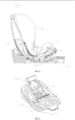
- the adjusting assembly 110 is disengaged from the connecting base 120, the seat body 130 can be disconnected from the connecting base 120 and the base 140 such that the rotation angle of the seat structure relative to the connecting base 120 is adjusted and the pitch angle of the seat body 130 relative to the connecting base 120 is adjusted.
- the rotation angle of the entire seat structure relative to the base 140 can be adjusted and the pitch angle of the seat body 130 relative to the connecting base 120 can also be adjusted.
- the rotation angle and the pitch angle can be adjusted simultaneously in a single operation. The convenience of operation is improved and the comfort for a child during use is also improved.
- the adjusting assembly 110 is mounted on the seat body 130, and is selectively connected to the connecting base 120; the adjusting assembly 110 can match or be disengaged from the connecting base 120; and when the adjusting assembly 110 is disengaged from the connecting base 120, the seat body 130 can adjust the pitch angle of the seat body relative to the connecting base 120 so as to improve the comfort for a child during use.
- the connecting base 120 is rotatably connected to the base 140, and the connecting base 120 can drive the seat body 130 to rotate and adjust the rotation angle and the pitch angle of the seat body 130, so that the rotation angle and the pitch angle relative to another position can be adjusted when a child sits in the safety seat 100.
- the base 140 is mounted on a saddle of a vehicle, and a child usually sits on the seat body 130.
- the rotatable connection between the connecting base 120 and the base 140 is mainly used to adjust the rotation angle of the seat body 130, and the adjusting assembly 110 is mainly configured to adjust the pitch angle of the seat body 130 relative to the saddle.
- the adjusting assembly 110 matches the connecting base 120 to fix the seat body 130 to the connecting base 120.
- the connecting base 120 can drive the seat body 130 to rotate relative to the base 140. That is to say, when the seat body 130 can rotate relative to the base 140 under the driving of the connecting base 120 at any pitch angle of the connecting base 120, the convenience of adjusting the entire safety seat 100 is improved.
- the adjusting assembly 110 comprises a connecting portion 112, a fixing member 114 and an elastic member 116, wherein one end of the elastic member 116 is connected to the connecting base 120, the other end thereof is connected to the fixing member 114, the fixing member 114 is fixed to the connecting portion 112, the fixing member 114 selectively matches the connecting base 120, and the connecting portion 112 is configured to drive the fixing member 114 to move away from the connecting base 120 under the action of an external force, so that the fixing member 114 is disengaged from the connecting base 120, and the seat body 130 can adjust the pitch angle of the seat body relative to the connecting base 120; and the elastic member 116 drives the fixing member 114 to move close to the connecting base 120 when the external force is removed, so that the fixing member 114 matches the connecting base 120, and the seat body 130 is fixedly connected to the connecting base 120.
- the connecting portion 112 drives the fixing member 114 to move in a direction away from the connecting base 120, so that the fixing member 114 is disengaged from the connecting base 120.
- the connecting base 120 and the seat body 130 can move relative to each other, and a user may need to adjust the pitch angle of the seat body 130 relative to the connecting base 120 and the rotatable connection of the entire seat structure relative to the base 140.
- the fixing member 114 moves in a direction close to the connecting base 120, so that the fixing member 114 and the connecting base 120 match each other, thereby fixing the seat body 130 to the connecting base 120, and ensuring the safety performance of the safety seat 100 during the driving of the vehicle.
- the fixing member 114 comprises a first fixing portion 1141, a second fixing portion 122 is arranged on the connecting base 120, and the first fixing portion 1141 selectively matches the second fixing portion 122; and when an external force is applied to the connecting portion 112, the first fixing portion 1141 is disengaged from the second fixing portion 122, and when the external force is removed, the first fixing portion 1141 matches the second fixing portion 122.
- the first fixing portion 1141 is a fixing post
- the second fixing portion 122 is a fixing hole formed in the connecting base 120.
- first fixing portion 1141 may be a fixing hole
- second fixing portion 122 may be a fixing hole formed in the seat body 130.
- first fixing portion 1141 and the second fixing portion 122 match each other by means of the fixing post and the fixing hole, but the means are not limited thereto.
- first fixing portion 1141 and the second fixing portion 122 may be fixedly connected by means of a buckle or by other means, and solutions equivalent to that of this embodiment fall within the scope of protection of the present invention provided that the solutions can achieve the effects of this embodiment.
- the fixing member 114 comprises a first guide portion 1143
- the adjusting assembly 110 further comprises a connecting housing 118
- the connecting housing 118 is fixedly connected to the connecting base 120
- a second guide portion 119 is arranged on the connecting housing 118
- the first guide portion 1143 matches the second guide portion 119
- the first guide portion 1143 slides in an extension direction of the second guide portion 119, so that the first fixing portion 1141 moves away from the second fixing portion 122, and is disengaged from the second fixing portion 122.
- the movement of the connecting portion 112 relative to the connecting base 120 drives the first guide portion 1143 to slide in the extension direction of the second guide portion 119, so that the first fixing portion 1141 gradually moves in the direction away from the second fixing portion 122.
- the first guide portion 1143 also moves in the extension direction of the second guide portion 119, so that the first fixing portion 1141 moves in a direction close to the second fixing portion 122 until the first fixing portion matches the second fixing portion 122.
- the second guide portion 119 is a guide groove provided in the connecting housing 118, the first guide portion 1143 is accommodated in the guide groove, and when the external force is applied to the connecting portion 112, the first guide portion 1143 slides in an extension direction of the guide groove, so that the first fixing portion 1141 is separated from the second fixing portion 122.
- the connecting housing 118 is roughly rectangular, and when the external force is applied to the connecting portion 112, the connecting portion 112 slides in a length direction of the connecting housing 118, and the guide groove is provided in a width direction of the connecting housing 118, thereby driving the first fixing portion 1141 to move in the width direction of the connecting housing 118, and disengaging the first fixing portion 1141 from the second fixing portion 122.
- the second guide portion 119 is arranged obliquely.
- the second guide portion 119 has two opposite ends, the first end is arranged close to the second fixing portion 122, and the second end is arranged away from the second fixing portion 122, wherein the first end is arranged close to the connecting portion 112, and the second end is arranged away from the connecting portion 112.
- the connecting portion 112 slides in the extension direction of the connecting housing 118, and the first guide portion 1143 abuts against an inner wall of the guide groove, so that the first fixing portion 1141 moves in the direction away from the second fixing portion 122.
- first fixing portion 1141 and the first guide portion 1143 are fixedly connected to each other, and the connecting portion 112 may be fixedly connected to any one of the first fixing portion 1141 and the first guide portion 1143.
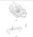
- a positioning member 124 is arranged on the connecting base 120, a clamping member 131 is further arranged on the seat body 130, the positioning member 124 is connected to the clamping member 131, and the clamping member 131 is selectively fixed to the base 140; when the adjusting assembly 110 is disengaged from the connecting base 120, the positioning member 124 can drive the clamping member 131 to move relative to the connecting base 120, so that the clamping member 131 is disengaged from the base 140, and the seat structure can rotate relative to the base 140, and adjusts the pitch angle of the seat body 130 relative to the connecting base 120.
- the seat body 130 when the adjusting assembly 110 is disengaged from the connecting base 120, the seat body 130 can slide relative to the connecting base 120 by pulling the adjusting assembly 110. During sliding, the positioning member 124 enables the clamping member 131 to move in the direction away from the base 140, so that the clamping member 131 is unfixed from the base 140. At this time, the entire seat structure can rotate relative to the base 140, thereby adjusting the rotation angle of the entire seat structure body relative to the connecting base 120. At the same time, during the sliding of the seat body 130 relative to the connecting base 120, the seat body 130 can adjust the pitch angle of the seat body relative to the connecting base 120.
- the entire seat structure rotates relative to the base 140 while the pitch angle relative to the connecting base 120 is adjusted, and at the same time, the rotation angle of the entire seat structure relative to the base 140 is adjusted.
- the clamping member 131 comprises a positioning portion 132 and a clamping portion 133
- the base 140 is further provided with a clamping groove 142
- the positioning portion 132 matches the positioning member 124
- the positioning portion 132 is fixedly connected to the clamping portion 133
- the positioning member 124 can drive the clamping portion 133 to move in a direction close to or away from the clamping groove 142 by means of the positioning portion 132, so that the clamping portion 133 matches or is disengaged from the clamping groove 142.
- the positioning member 124 is mounted on the connecting base 120. During the sliding of the seat body 130 relative to the connecting base 120, the positioning member 124 abuts against the positioning portion 132, so that the positioning portion 132 drives the clamping portion 133 to move in the direction away from the clamping groove 142. When the clamping portion 133 is disconnected from the clamping groove 142, the entire seat structure can rotate relative to the base 140, and the rotation angle of the seat structure relative to the base 140 is adjusted.
- the positioning member 124 comprises a fixing plate 127 and a plurality of stop portions 126 spaced on the fixing plate 127, and a positioning groove is formed between two adjacent stop portions 126; when the clamping member 131 abuts against the stop portions 126, the clamping member 131 is disconnected from the connecting base 120; and when the clamping member 131 matches the positioning groove, the clamping member 131 matches the base 140.
- the clamping portion 133 is disconnected from the clamping groove 142, and currently the entire seat structure can rotate relative to the base 140; and when the positioning portion 132 slides to match a positioning groove, the clamping portion 133 is fixedly connected to the clamping groove 142, so that the entire seat structure is fixedly connected to the base 140.
- the positioning portion 132 slides into any positioning groove and can be fixed to any positioning groove.
- the positioning portion 132 slides to abut against the stop portion 126, it indicates that currently the clamping portion 133 is disconnected from the clamping groove 142, and the rotation angle of the entire seat structure relative to the base 140 can be adjusted.
- the rotation angle can be adjusted while the pitch angle is adjusted, and one positioning groove corresponds to one pitch angle of the seat body 130 relative to the connecting base 120, that is, a larger number of stop portions 126 indicates more adjustable pitch angles of the seat body 130.
- the number of the clamping grooves 142 is equal to that of the positioning grooves, and the clamping grooves 142 and the positioning grooves are provided in a one-to-one correspondence manner, that is, when the positioning portion 132 is clamped into one positioning groove, the clamping portion 133 is also clamped into one clamping groove 142.
- each of the stop portions 126 has an obliquely arranged guide face 128, and the guide face 128 extends to a bottom wall of the positioning groove.
- the guide face 128 can guide the positioning member 124, thereby reducing the resistance to the sliding of the positioning member 124 out of the clamping member 131, and improving the convenience of adjusting the pitch angle of the seat body 130.
- the positioning portion 132 comprises an elastic portion 134 and an abutting portion 136, wherein one end of the elastic portion 134 is connected to the clamping portion 133, the other end thereof is connected to the abutting portion 136, and the abutting portion 136 matches the clamping member 131.
- the positioning portion 132 comprises an elastic portion 134 and an abutting portion 136, wherein one end of the elastic portion 134 is connected to the seat body 130, the other end thereof is connected to the abutting portion 136, and the abutting portion 136 matches the positioning member 124.
- a top surface of the protruding stop portion 126 relatively abuts against the abutting portion 136 when the abutting portion 136 slides onto the stop portion 126, so that the elastic portion 134 is retracted.
- the abutting portion 136 slides into the recessed positioning groove, the abutting portion 136 is quickly clamped into the positioning groove under the action of a restoring force of the elastic portion 134, and the positioning effect between the abutting portion 136 and the positioning groove is improved.
- the operating principle of the safety seat 100 is as follows: in this embodiment, when the pitch angle of the seat body 130 or the rotation angle of the entire seat structure relative to the base 140 needs to be adjusted, the external force is applied to the connecting portion 112, and the movement of the connecting portion 112 relative to the connecting base 120 drives the first guide portion 1143 to slide in the extension direction of the second guide portion 119, so that the first fixing portion 1141 gradually moves in the direction away from the second fixing portion 122, and the first fixing portion 1141 is disengaged from the second fixing portion 122.
- the seat body 130 is pushed, so that the clamping member 131 slides relative to the positioning member 124.
- the rotation angle of the entire seat structure relative to the base 140 can be adjusted.
- the abutting portion 136 is clamped into the positioning groove corresponding to the pitch angle, so as to implement the positioning of the seat body 130.
- the external force is removed, and the first guide portion 1143 also moves in the extension direction of the second guide portion 119, so that the first fixing portion 1141 moves in the direction close to the second fixing portion 122 until the first fixing portion matches the second fixing portion 122 to fix the seat body 130 to the connecting base 120.
- the rotation angle of the entire seat structure relative to the base 140 can be adjusted and the pitch angle of the seat body 130 relative to the connecting base 120 can also be adjusted.
- the rotation angle and the pitch angle can be adjusted simultaneously in a single operation. The convenience of operation is improved and the comfort for a child during use is also improved.
Landscapes
- Engineering & Computer Science (AREA)
- Health & Medical Sciences (AREA)
- Child & Adolescent Psychology (AREA)
- General Health & Medical Sciences (AREA)
- Aviation & Aerospace Engineering (AREA)
- Transportation (AREA)
- Mechanical Engineering (AREA)
- Seats For Vehicles (AREA)
- Chair Legs, Seat Parts, And Backrests (AREA)
Claims (8)
- Sicherheitssitz (100), der Folgendes umfasst: eine Sitzstruktur und eine Basis (140), wobei die Sitzstruktur und die Basis (140) drehbar verbunden sind, und die Sitzstruktur eine Verbindungsbasis (120), eine Einstellanordnung (110) und einen Sitzkörper (130) umfasst; der Sitzkörper (130) an der Verbindungsbasis (120) montiert ist und die Einstellanordnung (110) an dem Sitzkörper (130) montiert und mit der Verbindungsbasis (120) selektiv verbunden ist; und wenn die Einstellanordnung (110) von der Verbindungsbasis (120) gelöst wird, der Sitzkörper (130) von der Verbindungsbasis (120) und der Basis (140) getrennt wird, so dass der Drehwinkel der Sitzstruktur im Verhältnis zur Verbindungsbasis (120) eingestellt wird und der Neigungswinkel des Sitzkörpers (130) im Verhältnis zur Verbindungsbasis (120) eingestellt wird, wobei die Einstellanordnung (110) einen Verbindungsabschnitt (112), ein Befestigungselement (114) und ein elastisches Element (116) umfasst, wobei ein Ende des elastischen Elements (116) mit der Verbindungsbasis (120) verbunden ist, das andere Ende davon mit dem Befestigungselement (114) verbunden ist, das Befestigungselement (114) an dem Verbindungsabschnitt (112) befestigt ist, das Befestigungselement (114) selektiv mit der Verbindungsbasis (120) zusammenpasst, und der Verbindungsabschnitt (112) dazu konfiguriert ist, das Befestigungselement (114) so anzutreiben, dass es sich unter der Wirkung einer äußeren Kraft von der Verbindungsbasis (120) weg bewegt, so dass das Befestigungselement (114) von der Verbindungsbasis (120) gelöst wird und der Sitzkörper (130) den Neigungswinkel des Sitzkörpers im Verhältnis zur Verbindungsbasis (120) und den Drehungswinkel der Sitzstruktur im Verhältnis zur Basis (140) einstellen kann; und das elastische Element (116) das Befestigungselement (114) so antreibt, dass es sich näher zur Verbindungsbasis (120) bewegt, wenn die äußere Kraft entfernt wird, so dass das Befestigungselement (114) mit der Verbindungsbasis (120) zusammenpasst, und der Sitzkörper (130) fest mit der Verbindungsbasis (120) verbunden ist, wobei das Befestigungselement (114) einen ersten Befestigungsabschnitt (1141) umfasst, ein zweiter Befestigungsabschnitt (122) an der Verbindungsbasis (120) angeordnet ist, der erste Befestigungsabschnitt (1141) eine Befestigungsstange ist, der zweite Befestigungsabschnitt (122) ein in der Verbindungsbasis (120) ausgebildetes Befestigungsloch ist, und der erste Befestigungsabschnitt (1141) selektiv mit dem zweiten Befestigungsabschnitt (122) zusammenpasst; und wenn eine äußere Kraft auf den Verbindungsabschnitt (112) angewandt wird, der erste Befestigungsabschnitt (1141) von dem zweiten Befestigungsabschnitt (122) gelöst wird, und wenn die äußere Kraft entfernt wird, der erste Befestigungsabschnitt (1141) mit dem zweiten Befestigungsabschnitt (122) zusammenpasst.
- Sicherheitssitz (100) nach Anspruch 1, dadurch gekennzeichnet, dass das Befestigungselement (114) einen ersten Führungsabschnitt (1143) umfasst, die Einstellanordnung (110) ferner ein Verbindungsgehäuse (118) umfasst, das Verbindungsgehäuse (118) fest mit der Verbindungsbasis (120) verbunden ist, ein zweiter Führungsabschnitt (119) am Verbindungsgehäuse (118) angeordnet ist, der erste Führungsabschnitt (1143) mit dem zweiten Führungsabschnitt (119) zusammenpasst, und wenn die äußere Kraft auf den Verbindungsabschnitt (112) angewandt wird, der erste Führungsabschnitt (1143) in einer Verlängerungsrichtung des zweiten Führungsabschnitts (119) gleitet, so dass sich der erste Befestigungsabschnitt (1141) von dem zweiten Führungsabschnitt (122) weg bewegt und von dem zweiten Befestigungsabschnitt (122) gelöst wird.
- Sicherheitssitz (100) nach Anspruch 2, dadurch gekennzeichnet, dass der zweite Führungsabschnitt (119) schräg angeordnet ist.
- Sicherheitssitz (100) nach Anspruch 1, dadurch gekennzeichnet, dass ein Positionierungselement (124) an der Verbindungsbasis (120) angeordnet ist, ein Klemmelement (131) ferner am Sitzkörper (130) angeordnet ist, das Positionierungselement (124) mit dem Klemmelement (131) verbunden ist, und das Klemmelement (131) selektiv an der Basis (140) befestigt ist; wenn die Einstellanordnung (110) von der Verbindungsbasis (120) gelöst wird, kann das Positionierungselement (124) das Klemmelement (131) so antreiben, dass es sich im Verhältnis zur Verbindungsbasis (120) bewegt, so dass das Klemmelement (131) von der Basis (140) gelöst wird, und die Sitzstruktur im Verhältnis zur Basis (140) drehbar ist und den Neigungswinkel des Sitzkörpers (130) im Verhältnis zur Verbindungsbasis (120) einstellt.
- Sicherheitssitz (100) nach Anspruch 4, dadurch gekennzeichnet, dass das Klemmelement (131) einen Positionierungsabschnitt (132) und einen Klemmabschnitt (133) umfasst, die Basis (140) ferner mit einer Klemmnut (142) versehen ist, der Positionierungsabschnitt (132) mit dem Positionierungselement (124) zusammenpasst, der Positionierungsabschnitt (132) fest mit dem Klemmabschnitt (133) verbunden ist, und das Positionierungselement (124) den Klemmabschnitt (133) so antreiben kann, dass er sich mithilfe des Positionierungsabschnitts (132) in einer Richtung nahe zur Klemmnut (142) hin oder von dieser weg bewegt, so dass der Klemmabschnitt (133) mit der Klemmnut (142) zusammenpasst oder von dieser gelöst wird.
- Sicherheitssitz (100) nach Anspruch 5, dadurch gekennzeichnet, dass der Positionierungsabschnitt (132) einen elastischen Abschnitt (134) und einen Anlageabschnitt (136) umfasst, wobei ein Ende des elastischen Abschnitts (134) mit dem Klemmabschnitt (133) verbunden ist, das andere Ende davon mit dem Anlageabschnitt (136) verbunden ist, und der Anlageabschnitt (136) mit dem Klemmelement (131) zusammenpasst.
- Sicherheitssitz (100) nach Anspruch 4, dadurch gekennzeichnet, dass das Positionierungselement (124) eine Befestigungsplatte (127) und eine Vielzahl von Anschlagabschnitten (126), die an der Befestigungsplatte (127) beabstandet sind, umfasst, und eine Positionierungsnut zwischen zwei benachbarten Anschlagabschnitten (126) ausgebildet ist; wenn das Klemmelement (131) an den Anschlagabschnitten (126) anliegt, das Klemmelement (131) von der Verbindungsbasis (120) gelöst wird; und wenn das Klemmelement (131) mit der Positionierungsnut zusammenpasst, das Klemmelement (131) mit der Basis (140) zusammenpasst.
- Sicherheitssitz (100) nach Anspruch 7, dadurch gekennzeichnet, dass jeder der Anschlagabschnitte (126) eine schräg angeordnete Führungsfläche (128) aufweist und die Führungsfläche (128) sich zu einer unteren Wand der Positionierungsnut erstreckt.
Applications Claiming Priority (2)
| Application Number | Priority Date | Filing Date | Title |
|---|---|---|---|
| CN202011380172.8A CN112498196B (zh) | 2020-11-30 | 2020-11-30 | 一种安全座椅 |
| PCT/CN2021/098222 WO2022110751A1 (zh) | 2020-11-30 | 2021-06-04 | 一种安全座椅 |
Publications (4)
| Publication Number | Publication Date |
|---|---|
| EP4201736A1 EP4201736A1 (de) | 2023-06-28 |
| EP4201736A4 EP4201736A4 (de) | 2024-02-21 |
| EP4201736B1 true EP4201736B1 (de) | 2025-01-22 |
| EP4201736C0 EP4201736C0 (de) | 2025-01-22 |
Family
ID=74968183
Family Applications (1)
| Application Number | Title | Priority Date | Filing Date |
|---|---|---|---|
| EP21896260.3A Active EP4201736B1 (de) | 2020-11-30 | 2021-06-04 | Sicherheitssitz |
Country Status (5)
| Country | Link |
|---|---|
| US (1) | US12528390B2 (de) |
| EP (1) | EP4201736B1 (de) |
| CN (1) | CN112498196B (de) |
| AU (1) | AU2021385694B2 (de) |
| WO (1) | WO2022110751A1 (de) |
Families Citing this family (2)
| Publication number | Priority date | Publication date | Assignee | Title |
|---|---|---|---|---|
| CN112498196B (zh) * | 2020-11-30 | 2025-01-24 | 宁波宝贝第一母婴用品有限公司 | 一种安全座椅 |
| JP7720627B2 (ja) * | 2022-08-29 | 2025-08-08 | 株式会社シーエー産商 | チャイルドシート |
Family Cites Families (28)
| Publication number | Priority date | Publication date | Assignee | Title |
|---|---|---|---|---|
| EP1636063A1 (de) * | 2003-06-25 | 2006-03-22 | Catalyst Developments (Europe) Limited | Kindersicherheitssitz |
| CN102143861B (zh) * | 2008-07-02 | 2014-07-30 | 康贝株式会社 | 儿童座椅 |
| JP5436804B2 (ja) * | 2008-07-02 | 2014-03-05 | コンビ株式会社 | チャイルドシートおよびサポートレッグ |
| CN201847236U (zh) * | 2009-11-03 | 2011-06-01 | 明门香港股份有限公司 | 可调节倾斜角度的婴儿座椅及婴儿载具 |
| CN202219740U (zh) * | 2011-09-07 | 2012-05-16 | 宝钜儿童用品香港股份有限公司 | 儿童安全座椅及其角度调节机构 |
| CN203543727U (zh) * | 2012-11-02 | 2014-04-16 | 明门香港股份有限公司 | 可调节倾斜角度的安全座椅 |
| KR102214154B1 (ko) * | 2013-08-23 | 2021-02-09 | 콤비 가부시키가이샤 | 차일드 시트 |
| WO2016033738A1 (zh) * | 2014-09-02 | 2016-03-10 | 去致婴幼儿用品(深圳)有限公司 | 汽车安全座椅的安全保护装置 |
| KR101595115B1 (ko) * | 2014-12-11 | 2016-02-17 | 정종락 | 쿠션부가 구비된 유아용 카시트 |
| CN105034873B (zh) * | 2015-08-27 | 2017-11-17 | 江苏百佳斯特汽车制品有限公司 | 360度旋转及俯仰角调节的儿童安全座椅 |
| DE202015006701U1 (de) * | 2015-09-24 | 2015-10-09 | Tung Tzu Industrial Co., Ltd. | Neigungswinkel einstellbarer Kindersitz |
| CN113859069B (zh) * | 2016-03-08 | 2024-01-02 | 明门香港股份有限公司 | 儿童安全座椅 |
| WO2017179745A1 (ko) * | 2016-04-12 | 2017-10-19 | (주)동인기연 | 위치변경이 가능한 유아용 카시트 |
| US10322651B2 (en) * | 2016-06-14 | 2019-06-18 | Wonderland Switzerland Ag | Child safety seat |
| US10829012B1 (en) * | 2017-01-23 | 2020-11-10 | Graco Children's Products, Inc. | Method and apparatus for a rotatable child safety seat |
| DE102018010420B3 (de) * | 2017-03-17 | 2022-11-03 | Wonderland Switzerland Ag | Kindersicherheitssitz |
| CN207267463U (zh) * | 2017-07-13 | 2018-04-24 | 浙江感恩科技股份有限公司 | 一种儿童安全座椅的调节机构 |
| CN107187344B (zh) * | 2017-07-14 | 2023-05-30 | 浙江迈嘉婴童用品有限公司 | 角度调节结构及儿童安全座椅 |
| WO2019046990A1 (zh) * | 2017-09-07 | 2019-03-14 | 蒙祖胜 | 儿童安全座椅 |
| DE202017105584U1 (de) * | 2017-09-14 | 2018-12-17 | Cybex Gmbh | Kindersitzsystem, umfassend ein Sitzelement sowie eine auf einem Kraftfahrzeugsitz anbringbare Basis |
| CN109835219B (zh) * | 2017-11-27 | 2024-10-29 | 珠海阳光儿童用品有限公司 | 一种座椅姿态调整装置及安全座椅 |
| CN109532586B (zh) | 2018-12-20 | 2024-01-12 | 安徽永驰婴童科技股份有限公司 | 椅体旋转及仰俯角一体化调节机构及儿童安全座椅 |
| CN109795382A (zh) * | 2019-01-26 | 2019-05-24 | 宁波市博林日用品制造有限公司 | 一种儿童安全座椅 |
| CN210707009U (zh) * | 2019-07-04 | 2020-06-09 | 广东乐美达集团有限公司 | 可调节角度的安全座椅 |
| CN210337660U (zh) | 2019-08-29 | 2020-04-17 | 珠海弘点科技有限公司 | 儿童安全座椅 |
| CN211943043U (zh) * | 2020-03-11 | 2020-11-17 | 江苏安用座椅科技有限公司 | 一种便于调节倾斜角度及旋转角度的儿童安全座椅 |
| CN112498196B (zh) * | 2020-11-30 | 2025-01-24 | 宁波宝贝第一母婴用品有限公司 | 一种安全座椅 |
| CN213619477U (zh) * | 2020-11-30 | 2021-07-06 | 宁波宝贝第一母婴用品有限公司 | 一种安全座椅 |
-
2020
- 2020-11-30 CN CN202011380172.8A patent/CN112498196B/zh active Active
-
2021
- 2021-06-04 EP EP21896260.3A patent/EP4201736B1/de active Active
- 2021-06-04 WO PCT/CN2021/098222 patent/WO2022110751A1/zh not_active Ceased
- 2021-06-04 AU AU2021385694A patent/AU2021385694B2/en active Active
- 2021-06-04 US US18/028,561 patent/US12528390B2/en active Active
Also Published As
| Publication number | Publication date |
|---|---|
| CN112498196A (zh) | 2021-03-16 |
| US12528390B2 (en) | 2026-01-20 |
| CN112498196B (zh) | 2025-01-24 |
| AU2021385694B2 (en) | 2024-09-12 |
| AU2021385694A9 (en) | 2024-10-31 |
| US20230356632A1 (en) | 2023-11-09 |
| EP4201736A4 (de) | 2024-02-21 |
| WO2022110751A1 (zh) | 2022-06-02 |
| AU2021385694A1 (en) | 2023-05-18 |
| EP4201736A1 (de) | 2023-06-28 |
| EP4201736C0 (de) | 2025-01-22 |
Similar Documents
| Publication | Publication Date | Title |
|---|---|---|
| EP4201736B1 (de) | Sicherheitssitz | |
| AU679520B2 (en) | Child seat apparatus | |
| US4103970A (en) | Seat recliner | |
| EP2481316B1 (de) | Sitz | |
| US11667219B2 (en) | Child safety seat | |
| US9682639B2 (en) | Reclining apparatus for vehicle seat | |
| CN101670796A (zh) | 儿童安全座椅 | |
| US20120112513A1 (en) | Seatback for vehicle seat | |
| US20110169309A1 (en) | Inclination adjustment mechanism for a base of safety seat | |
| US20250010904A1 (en) | Infant carrier and backrest adjusting mechanism thereof | |
| EP3715175B1 (de) | Selbstrücksetzender einstellmechanismus | |
| US7604295B2 (en) | Child vehicle seat | |
| US7634212B2 (en) | Position adjustable control panel for image forming device | |
| US20070052271A1 (en) | Securing structure of a seat of a cart for use by the elderly and handicapped persons | |
| EP1442675B1 (de) | Liegesitz-Zusatzvorrichtung für ein Kind | |
| CN109123923B (zh) | 调节扣 | |
| CN213619477U (zh) | 一种安全座椅 | |
| CN105984482A (zh) | 婴儿车及其背靠角度调整装置 | |
| JP6154234B2 (ja) | リクライニング機構 | |
| JPH021143Y2 (de) | ||
| JP2540018Y2 (ja) | シートベルトの高さ調整装置 | |
| CN222793326U (zh) | 一种扶手调节机构 | |
| CN210979134U (zh) | 一种单指向旋转支架 | |
| CN118512087A (zh) | 用于椅子的扶手结构以及具有扶手结构的椅子 | |
| JPH08317829A (ja) | シートのリクライニング装置 |
Legal Events
| Date | Code | Title | Description |
|---|---|---|---|
| STAA | Information on the status of an ep patent application or granted ep patent |
Free format text: STATUS: THE INTERNATIONAL PUBLICATION HAS BEEN MADE |
|
| PUAI | Public reference made under article 153(3) epc to a published international application that has entered the european phase |
Free format text: ORIGINAL CODE: 0009012 |
|
| STAA | Information on the status of an ep patent application or granted ep patent |
Free format text: STATUS: REQUEST FOR EXAMINATION WAS MADE |
|
| 17P | Request for examination filed |
Effective date: 20230324 |
|
| AK | Designated contracting states |
Kind code of ref document: A1 Designated state(s): AL AT BE BG CH CY CZ DE DK EE ES FI FR GB GR HR HU IE IS IT LI LT LU LV MC MK MT NL NO PL PT RO RS SE SI SK SM TR |
|
| STAA | Information on the status of an ep patent application or granted ep patent |
Free format text: STATUS: EXAMINATION IS IN PROGRESS |
|
| A4 | Supplementary search report drawn up and despatched |
Effective date: 20240123 |
|
| RIC1 | Information provided on ipc code assigned before grant |
Ipc: B60N 2/28 20060101AFI20240117BHEP |
|
| 17Q | First examination report despatched |
Effective date: 20240202 |
|
| DAV | Request for validation of the european patent (deleted) | ||
| DAX | Request for extension of the european patent (deleted) | ||
| GRAP | Despatch of communication of intention to grant a patent |
Free format text: ORIGINAL CODE: EPIDOSNIGR1 |
|
| STAA | Information on the status of an ep patent application or granted ep patent |
Free format text: STATUS: GRANT OF PATENT IS INTENDED |
|
| INTG | Intention to grant announced |
Effective date: 20240916 |
|
| GRAS | Grant fee paid |
Free format text: ORIGINAL CODE: EPIDOSNIGR3 |
|
| GRAA | (expected) grant |
Free format text: ORIGINAL CODE: 0009210 |
|
| STAA | Information on the status of an ep patent application or granted ep patent |
Free format text: STATUS: THE PATENT HAS BEEN GRANTED |
|
| AK | Designated contracting states |
Kind code of ref document: B1 Designated state(s): AL AT BE BG CH CY CZ DE DK EE ES FI FR GB GR HR HU IE IS IT LI LT LU LV MC MK MT NL NO PL PT RO RS SE SI SK SM TR |
|
| REG | Reference to a national code |
Ref country code: GB Ref legal event code: FG4D |
|
| REG | Reference to a national code |
Ref country code: CH Ref legal event code: EP |
|
| REG | Reference to a national code |
Ref country code: IE Ref legal event code: FG4D |
|
| REG | Reference to a national code |
Ref country code: DE Ref legal event code: R096 Ref document number: 602021025252 Country of ref document: DE |
|
| U01 | Request for unitary effect filed |
Effective date: 20250211 |
|
| U07 | Unitary effect registered |
Designated state(s): AT BE BG DE DK EE FI FR IT LT LU LV MT NL PT RO SE SI Effective date: 20250217 |
|
| PG25 | Lapsed in a contracting state [announced via postgrant information from national office to epo] |
Ref country code: RS Free format text: LAPSE BECAUSE OF FAILURE TO SUBMIT A TRANSLATION OF THE DESCRIPTION OR TO PAY THE FEE WITHIN THE PRESCRIBED TIME-LIMIT Effective date: 20250422 |
|
| PG25 | Lapsed in a contracting state [announced via postgrant information from national office to epo] |
Ref country code: PL Free format text: LAPSE BECAUSE OF FAILURE TO SUBMIT A TRANSLATION OF THE DESCRIPTION OR TO PAY THE FEE WITHIN THE PRESCRIBED TIME-LIMIT Effective date: 20250122 |
|
| PG25 | Lapsed in a contracting state [announced via postgrant information from national office to epo] |
Ref country code: ES Free format text: LAPSE BECAUSE OF FAILURE TO SUBMIT A TRANSLATION OF THE DESCRIPTION OR TO PAY THE FEE WITHIN THE PRESCRIBED TIME-LIMIT Effective date: 20250122 |
|
| PGFP | Annual fee paid to national office [announced via postgrant information from national office to epo] |
Ref country code: GB Payment date: 20250630 Year of fee payment: 5 |
|
| PG25 | Lapsed in a contracting state [announced via postgrant information from national office to epo] |
Ref country code: NO Free format text: LAPSE BECAUSE OF FAILURE TO SUBMIT A TRANSLATION OF THE DESCRIPTION OR TO PAY THE FEE WITHIN THE PRESCRIBED TIME-LIMIT Effective date: 20250422 Ref country code: IS Free format text: LAPSE BECAUSE OF FAILURE TO SUBMIT A TRANSLATION OF THE DESCRIPTION OR TO PAY THE FEE WITHIN THE PRESCRIBED TIME-LIMIT Effective date: 20250522 |
|
| PG25 | Lapsed in a contracting state [announced via postgrant information from national office to epo] |
Ref country code: HR Free format text: LAPSE BECAUSE OF FAILURE TO SUBMIT A TRANSLATION OF THE DESCRIPTION OR TO PAY THE FEE WITHIN THE PRESCRIBED TIME-LIMIT Effective date: 20250122 |
|
| PG25 | Lapsed in a contracting state [announced via postgrant information from national office to epo] |
Ref country code: GR Free format text: LAPSE BECAUSE OF FAILURE TO SUBMIT A TRANSLATION OF THE DESCRIPTION OR TO PAY THE FEE WITHIN THE PRESCRIBED TIME-LIMIT Effective date: 20250423 |
|
| U20 | Renewal fee for the european patent with unitary effect paid |
Year of fee payment: 5 Effective date: 20250619 |
|
| PG25 | Lapsed in a contracting state [announced via postgrant information from national office to epo] |
Ref country code: SM Free format text: LAPSE BECAUSE OF FAILURE TO SUBMIT A TRANSLATION OF THE DESCRIPTION OR TO PAY THE FEE WITHIN THE PRESCRIBED TIME-LIMIT Effective date: 20250122 |
|
| PG25 | Lapsed in a contracting state [announced via postgrant information from national office to epo] |
Ref country code: CZ Free format text: LAPSE BECAUSE OF FAILURE TO SUBMIT A TRANSLATION OF THE DESCRIPTION OR TO PAY THE FEE WITHIN THE PRESCRIBED TIME-LIMIT Effective date: 20250122 |
|
| PG25 | Lapsed in a contracting state [announced via postgrant information from national office to epo] |
Ref country code: SK Free format text: LAPSE BECAUSE OF FAILURE TO SUBMIT A TRANSLATION OF THE DESCRIPTION OR TO PAY THE FEE WITHIN THE PRESCRIBED TIME-LIMIT Effective date: 20250122 |
|
| U1N | Appointed representative for the unitary patent procedure changed after the registration of the unitary effect |
Representative=s name: SANTARELLI; FR |
|
| PLBE | No opposition filed within time limit |
Free format text: ORIGINAL CODE: 0009261 |
|
| STAA | Information on the status of an ep patent application or granted ep patent |
Free format text: STATUS: NO OPPOSITION FILED WITHIN TIME LIMIT |
|
| REG | Reference to a national code |
Ref country code: CH Ref legal event code: L10 Free format text: ST27 STATUS EVENT CODE: U-0-0-L10-L00 (AS PROVIDED BY THE NATIONAL OFFICE) Effective date: 20251203 |
|
| 26N | No opposition filed |
Effective date: 20251023 |
|
| REG | Reference to a national code |
Ref country code: CH Ref legal event code: H13 Free format text: ST27 STATUS EVENT CODE: U-0-0-H10-H13 (AS PROVIDED BY THE NATIONAL OFFICE) Effective date: 20260127 |
|
| PG25 | Lapsed in a contracting state [announced via postgrant information from national office to epo] |
Ref country code: MC Free format text: LAPSE BECAUSE OF FAILURE TO SUBMIT A TRANSLATION OF THE DESCRIPTION OR TO PAY THE FEE WITHIN THE PRESCRIBED TIME-LIMIT Effective date: 20250122 |