EP4201718A1 - Luftführungselement für kraftfahrzeuge - Google Patents
Luftführungselement für kraftfahrzeuge Download PDFInfo
- Publication number
- EP4201718A1 EP4201718A1 EP22214193.9A EP22214193A EP4201718A1 EP 4201718 A1 EP4201718 A1 EP 4201718A1 EP 22214193 A EP22214193 A EP 22214193A EP 4201718 A1 EP4201718 A1 EP 4201718A1
- Authority
- EP
- European Patent Office
- Prior art keywords
- air
- hollow body
- additional
- cross
- additional bodies
- Prior art date
- Legal status (The legal status is an assumption and is not a legal conclusion. Google has not performed a legal analysis and makes no representation as to the accuracy of the status listed.)
- Granted
Links
Images
Classifications
-
- B—PERFORMING OPERATIONS; TRANSPORTING
- B60—VEHICLES IN GENERAL
- B60H—ARRANGEMENTS OF HEATING, COOLING, VENTILATING OR OTHER AIR-TREATING DEVICES SPECIALLY ADAPTED FOR PASSENGER OR GOODS SPACES OF VEHICLES
- B60H1/00—Heating, cooling or ventilating devices
- B60H1/00507—Details, e.g. mounting arrangements, desaeration devices
- B60H1/00557—Details of ducts or cables
- B60H1/00564—Details of ducts or cables of air ducts
-
- B—PERFORMING OPERATIONS; TRANSPORTING
- B60—VEHICLES IN GENERAL
- B60H—ARRANGEMENTS OF HEATING, COOLING, VENTILATING OR OTHER AIR-TREATING DEVICES SPECIALLY ADAPTED FOR PASSENGER OR GOODS SPACES OF VEHICLES
- B60H1/00—Heating, cooling or ventilating devices
- B60H1/00507—Details, e.g. mounting arrangements, desaeration devices
- B60H2001/006—Noise reduction
-
- F—MECHANICAL ENGINEERING; LIGHTING; HEATING; WEAPONS; BLASTING
- F16—ENGINEERING ELEMENTS AND UNITS; GENERAL MEASURES FOR PRODUCING AND MAINTAINING EFFECTIVE FUNCTIONING OF MACHINES OR INSTALLATIONS; THERMAL INSULATION IN GENERAL
- F16L—PIPES; JOINTS OR FITTINGS FOR PIPES; SUPPORTS FOR PIPES, CABLES OR PROTECTIVE TUBING; MEANS FOR THERMAL INSULATION IN GENERAL
- F16L55/00—Devices or appurtenances for use in, or in connection with, pipes or pipe systems
- F16L55/02—Energy absorbers; Noise absorbers
- F16L55/033—Noise absorbers
- F16L55/0331—Noise absorbers by inserting an elongated element in the pipe
-
- F—MECHANICAL ENGINEERING; LIGHTING; HEATING; WEAPONS; BLASTING
- F16—ENGINEERING ELEMENTS AND UNITS; GENERAL MEASURES FOR PRODUCING AND MAINTAINING EFFECTIVE FUNCTIONING OF MACHINES OR INSTALLATIONS; THERMAL INSULATION IN GENERAL
- F16L—PIPES; JOINTS OR FITTINGS FOR PIPES; SUPPORTS FOR PIPES, CABLES OR PROTECTIVE TUBING; MEANS FOR THERMAL INSULATION IN GENERAL
- F16L55/00—Devices or appurtenances for use in, or in connection with, pipes or pipe systems
- F16L55/02—Energy absorbers; Noise absorbers
- F16L55/033—Noise absorbers
- F16L55/0336—Noise absorbers by means of sound-absorbing materials
Definitions
- the present invention relates to an air duct element for motor vehicles with at least one elongated hollow body, the inner wall of which defines an air duct, sound-absorbing additional bodies being provided in the hollow body along its longitudinal extension direction, which are arranged and fastened in the hollow body in such a way that air flowing in the hollow body along the air duct flows, also flows along the additional bodies and interacts with them, the additional bodies having different thicknesses and the additional bodies absorbing a different frequency Y of the sound transmitted through the air, depending on the thickness.
- a generic air guide element can disclosure EP 3 838 637 A1 be removed.
- the disadvantage of such an air duct is that the thickness of the sound-absorbing additional bodies is based on the existing cross-section of the air duct and as a result too many or too long additional bodies are used. As a result, the speed of the air flowing through the air guiding element is reduced to a greater extent than would be necessary for the desired sound absorption.
- reduced speeds of the air to be conveyed lead to the need to use more powerful blowers with high energy consumption.
- the invention therefore sets itself the task of constructing a generic air guiding element in such a way that the thickness of the additional bodies is optimized and the reduction in the speed of the flowing air is minimized.
- the necessary thicknesses for the absorption of sound of a specific frequency can be calculated in a targeted and optimized manner.
- the speed of sound in dry air at 20°C is 343.2 m/s (meters per second).
- the frequencies to be absorbed are preferably in the range between 800 Hertz and 2500 Hertz. This corresponds to the range that is most sensitive to human hearing.
- the thicknesses of the additional bodies can be varied continuously or in stages.
- the elongate hollow body has cross-sectional areas that vary along its direction of longitudinal extension, and the additional bodies are positioned within the hollow body in such a way that the difference between the cross-sectional area and Surface of the additional body varies from each other with a maximum deviation of 20%, so that the remaining cross-sectional area in the flow direction of the air remains largely constant.
- the additional bodies can be made up of a single layer or of several layers.
- the additional bodies can in particular be formed from a fleece material, preferably from a PET fleece material.
- the sides of the additional bodies that face the air flowing through also have a microperforated surface, preferably formed by a microperforated film, in particular by a microperforated PP film.
- the hollow body can be formed by at least two shells connected to one another.
- the hollow body can be designed as a one-piece blow-molded hollow body.
- the elongated hollow body can be round, oval, square and/or polygonal in cross section.
- an air guide element for motor vehicles is shown with at least one elongated hollow body 1 whose inner wall weeps air guide channel 2 .
- additional sound-absorbing bodies 3, 4 are provided, which are arranged and fastened in the hollow body 1 in such a way that air which flows in the hollow body 1 along the air duct 2 is additionally absorbed by the additional bodies 3, 4 flows along and interacts with them, wherein the additional bodies 3, 4 have different thicknesses d1, d2 and the additional bodies 3, 4 absorb a different frequency Y of the sound transmitted through the air depending on the thickness d1, d2.
- the frequencies to be absorbed are between 800 Hertz and 2500 Hertz.
- the variation of the thicknesses d1, d2 of the additional bodies 3, 4 is graded here.
- the elongated hollow body 1 has cross-sectional areas that vary in the direction of its longitudinal extent, and the additional bodies 3, 4 are positioned within the hollow body 1 in such a way that the difference between the cross-sectional area and the area of the additional body 3, 4 varies by a maximum deviation of 20% from one another, so that the remaining cross-sectional area in the flow direction of the air remains largely constant.
- the additional bodies 3, 4 are made up of a single layer or of several layers.
- the additional bodies 3, 4 are formed from a fleece material, preferably from a PET fleece material.
- the sides of the additional bodies 3, 4 facing the air flowing through also have a micro-perforated surface, preferably formed by a micro-perforated film, in particular by a micro-perforated PP film.
Landscapes
- Physics & Mathematics (AREA)
- Thermal Sciences (AREA)
- Engineering & Computer Science (AREA)
- Mechanical Engineering (AREA)
- Duct Arrangements (AREA)
- Air-Conditioning For Vehicles (AREA)
Abstract
Description
- Die vorliegende Erfindung betrifft ein Luftführungselement für Kraftfahrzeuge mit mindestens einem langgestreckten Hohlkörper dessen Innenwandung einen Luftführungskanal vorgibt, wobei in dem Hohlkörper entlang seiner Längserstreckungsrichtung schallabsorbierende Zusatzkörper vorgesehen sind, die in dem Hohlkörper so angeordnet und befestigt sind, dass Luft, welche im Hohlkörper entlang des Luftkanals strömt, zusätzlich an den Zusatzkörpern entlang strömt und mit diesen wechselwirkt, wobei die Zusatzkörper unterschiedliche Dicken aufweisen und die Zusatzkörper je nach Dicke eine andere Frequenz Y des durch die Luft übertragenen Schalls absorbieren.
- Ein gattungsgemäßes Luftführungselement kann der Offenlegung
EP 3 838 637 A1 entnommen werden. Nachteilig an einer derartigen Luftführung ist, dass die schallabsorbierenden Zusatzkörper in ihrer Dicke anhand des vorhandenen Querschnitts des Luftführungskanals orientieren und hierdurch zu viele oder zu lange Zusatzkörper verwendet werden. Die Geschwindigkeit der durch das Luftführungselement strömenden Luft wird hierdurch stärker reduziert als es für die gewünschte Schallabsorption notwendig wäre. Bei der Verwendung in der Klimaanlage eines Kraftfahrzeuges führen reduzierte Geschwindigkeiten der zu fördernden Luft zur Notwendigkeit leistungsstärkere Gebläse mit hohem Energieverbrauch zu verwenden. - Die Erfindung stellt sich daher die Aufgabe ein gattungsgemäßes Luftführungselement so zu konstruieren, dass die Dicke der Zusatzkörper optimiert und die Reduktion der Geschwindigkeit der strömenden Luft minimiert wird.
- Diese Aufgabe wird erfindungsgemäß gelöst durch ein Luftführungselement für Kraftfahrzeuge mit mindestens einem langgestreckten Hohlkörper dessen Innenwandung einen Luftführungskanal vorgibt, wobei in dem Hohlkörper entlang seiner Längserstreckungsrichtung schallabsorbierende Zusatzkörper vorgesehen sind, die in dem Hohlkörper so angeordnet und befestigt sind, dass Luft, welche im Hohlkörper entlang des Luftkanals strömt, zusätzlich an den Zusatzkörpern entlang strömt und mit diesen wechselwirkt, wobei die Zusatzkörper unterschiedliche Dicken aufweisen und die Zusatzkörper je nach Dicke eine andere Frequenz Y des durch die Luft übertragenen Schalls absorbieren, wobei sich die Dicken der Zusatzkörper in Abhängigkeit zu den durch das Luftführungselement zu absorbierenden Frequenzen Y wie folgt definieren:

- Durch die erfindungsgemäße Berechnung der Dicke der Zusatzkörper anhand der obenstehenden Formel, lassen sich die notwenigen Dicken zur Absorption von Schall einer bestimmten Frequenz gezielt und optimiert berechnen. Es wird hierdurch weder ein zu dicker, noch ein zu dünner Zusatzkörper in dem Luftführungselement verwendet. Die Schallgeschwindigkeit in trockener Luft von 20 °C ist 343,2 m/s (Meter pro Sekunde).
- Die zu absorbierenden Frequenzen liegen hierbei bevorzugt im Bereich zwischen 800 Hertz und 2500 Hertz. Dies entspricht dem Bereich, der für das menschliche Gehör am empfindlichsten wahrnehmbar ist.
- Die Variation der Dicken der Zusatzkörper kann kontinuierlich oder gestuft erfolgen.
- Der langgestreckte Hohlkörper weist in einer Variante der Erfindung entlang seiner Längserstreckungsrichtung variierende Querschnittsflächen auf und die Zusatzkörper werden so innerhalb des Hohlkörpers positioniert, das die Differenz aus Querschnittsfläche und Fläche des Zusatzkörpers jeweils mit einer Abweichung von höchsten 20% zueinander variiert, damit die verbleibende Restquerschnittsfläche in Strömungsrichtung der Luft weitestgehend konstant bleibt.
- Die Zusatzkörper können aus einer einzelnen Schicht oder aus mehreren Schichten aufgebaut sein.
- Die Zusatzkörper können insbesondere aus einem Vliesmaterial, vorzugsweise aus einem PET-Vliesmaterial gebildet sein.
- Die der durchströmenden Luft zugewandten Seiten der Zusatzkörper weisen in einer bevorzugten Ausführungsform der Erfindung zusätzlich eine mikroperforierte Oberfläche, vorzugsweise gebildet durch eine mikroperforierte Folie, insbesondere durch eine mikroperforierte PP-Folie, auf.
- Der Hohlkörper kann durch wenigsten zwei miteinander verbundene Schalen gebildet sein. Alternativ kann der Hohlkörper als einstückig ausgebildeter Blasform-Hohlkörper ausgebildet sein.
- Der langgestreckte Hohlkörper kann im Querschnitt rund, oval, viereckig und/oder vieleckig ausgebildet sein.
- Teil der Erfindung ist ferner eine Verfahren, das wie folgt definiert ist:
Verfahren zur Herstellung eines Luftführungselements für Kraftfahrzeuge mit mindestens einem langgestreckten Hohlkörper dessen Innenwandung einen Luftführungskanal vorgibt, wobei der Hohlkörper entlang seiner Längserstreckungsrichtung variierende Querschnittsflächen aufweist, wobei innerhalb des Hohlkörpers schallabsorbierende Zusatzkörper vorgesehen sind, die so innerhalb des Hohlkörpers angeordnet sind, dass Luft, welche im Hohlkörper entlang des Luftkanals strömt, zusätzlich an den Zusatzkörpern entlang strömt und mit diesem wechselwirkt, wobei dass das Verfahren folgende Schritte umfasst: - Bereitstellen des Luftführungselements,
- Bestimmen eines Querschnitt-Segments der Luftführung bei dem die Querschnittsfläche größer ist als die Querschnittsfläche des an dieses Querschnitt-Segment angrenzenden weiteren Querschnitt-Segments der Luftführung,
- Nutzen des Differenz-Raums des Querschnitt-Segments im Vergleich zu dem Raum des angrenzenden weiteren Querschnitt-Segments zur Platzierung eines der schallabsorbierenden Zusatzkörper innerhalb dieses Differenz-Raums,
- Bestimmen einer maximalen Dicke des Zusatzkörpers anhand der Höhe des Differenz-Raums,
- Berechnen des möglichen zu absorbierenden Frequenzspektrums anhand der bestimmten maximal zur Verfügung stehenden Dicke des Zusatzkörpers,
- Auswählen einer Dicke des Zusatzkörpers zur Absorption einer spezifischen Frequenz des Schalls der transportierten Luft aus dem berechneten möglichen Frequenzspektrum anhand der Formel:

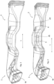
- Im Folgenden wird die Erfindung anhand lediglich Ausführungsbeispiele darstellender Zeichnung erläutert. Es zeigen schematisch:
- Fig. 1
- Frontalansicht eines Luftführungselements;
- Fig. 2
- eine Querschnittsdarstellung durch das Luftführungselement aus
Fig. 1 . - In den Figuren werden gleiche oder funktionsgleiche Elemente mit den gleichen Bezugszeichen versehen.
- In
Fig. 1 ist ein Luftführungselement für Kraftfahrzeuge mit mindestens einem langgestreckten Hohlkörper 1 dessen Innenwandung Weinen Luftführungskanal 2 vorgibt dargestellt. - In
Fig. 2 ist erkennbar, dass in dem Hohlkörper 1 entlang seiner Längserstreckungsrichtung L schallabsorbierende Zusatzkörper 3, 4 vorgesehen sind, die in dem Hohlkörper 1 so angeordnet und befestigt sind, dass Luft, welche im Hohlkörper 1 entlang des Luftkanals 2 strömt, zusätzlich an den Zusatzkörpern 3, 4 entlang strömt und mit diesen wechselwirkt, wobei die Zusatzkörper 3, 4 unterschiedliche Dicken d1, d2 aufweisen und die Zusatzkörper 3, 4 je nach Dicke d1, d2 eine andere Frequenz Y des durch die Luft übertragenen Schalls absorbieren. - Die Dicken d1, d2 der Zusatzkörper 3, 4 definieren sich in Abhängigkeit zu den durch das Luftführungselement zu absorbierenden Frequenzen Y wie folgt:

- Die zu absorbierenden Frequenzen liegen in diesem Ausführungsbeispiel zwischen 800 Hertz und 2500 Hertz. Die Variation der Dicken d1, d2 der Zusatzkörper 3, 4 erfolgt hier gestuft.
- Der langgestreckte Hohlkörper 1 weist entlang seiner Längserstreckungsrichtung variierende Querschnittsflächen auf und die Zusatzkörper 3, 4 werden so innerhalb des Hohlkörpers 1 positioniert, das die Differenz aus Querschnittsfläche und Fläche des Zusatzkörpers 3, 4 jeweils mit einer Abweichung von höchsten 20% zueinander variiert, damit die verbleibende Restquerschnittsfläche in Strömungsrichtung der Luft weitestgehend konstant bleibt.
- Die Zusatzkörper 3, 4 sind aus einer einzelnen Schicht oder aus mehreren Schichten aufgebaut.
- Die Zusatzkörper 3, 4 sind aus einem Vliesmaterial, vorzugsweise aus einem PET-Vliesmaterial gebildet.
- Die der durchströmenden Luft zugewandten Seiten der Zusatzkörper 3, 4 weisen zusätzlich eine mikroperforierte Oberfläche, vorzugsweise gebildet durch eine mikroperforierte Folie, insbesondere durch eine mikroperforierte PP-Folie, auf.
Claims (10)
- Luftführungselement für Kraftfahrzeuge mit mindestens einem langgestreckten Hohlkörper (1) dessen Innenwandung (W) einen Luftführungskanal (2) vorgibt, wobei in dem Hohlkörper (1) entlang seiner Längserstreckungsrichtung (L) schallabsorbierende Zusatzkörper (3, 4) vorgesehen sind, die in dem Hohlkörper (1) so angeordnet und befestigt sind, dass Luft, welche im Hohlkörper (1) entlang des Luftkanals (2) strömt, zusätzlich an den Zusatzkörpern (3, 4) entlang strömt und mit diesen wechselwirkt, wobei die Zusatzkörper (3, 4) unterschiedliche Dicken (d1, d2) aufweisen und die Zusatzkörper (3, 4) je nach Dicke (d1, d2) eine andere Frequenz Y des durch die Luft übertragenen Schalls absorbieren,
dadurch gekennzeichnet, dasssich die Dicken (d1, d2) der Zusatzkörper (3, 4) in Abhängigkeit zu den durch das Luftführungselement zu absorbierenden Frequenzen Y wie folgt definieren: wobei X einen Wert zwischen 7 bis 9 einnimmt.
 - Luftführungselement nach Anspruch 1, dadurch gekennzeichnet, die zu absorbierenden Frequenzen zwischen 800 Hertz und 2500 Hertz liegen.
- Luftführungselement nach Anspruch 1 oder 2, dadurch gekennzeichnet, dass die Variation der Dicken (d1, d2) der Zusatzkörper (3, 4) kontinuierlich oder gestuft erfolgt.
- Luftführungselement nach einem der vorstehenden Ansprüche, dadurch gekennzeichnet, dass der langgestreckte Hohlkörper (1) entlang seiner Längserstreckungsrichtung variierende Querschnittsflächen aufweist und die Zusatzkörper (3, 4) so innerhalb des Hohlkörpers (1) positioniert werden, das die Differenz aus Querschnittsfläche und Fläche des Zusatzkörpers (3, 4) jeweils mit einer Abweichung von höchsten 20% zueinander variiert, damit die verbleibende Restquerschnittsfläche in Strömungsrichtung der Luft weitestgehend konstant bleibt.
- Luftführungselement nach einem der vorstehenden Ansprüche, dadurch gekennzeichnet, dass die Zusatzkörper (3, 4) aus einer einzelnen Schicht oder aus mehreren Schichten aufgebaut ist oder sind.
- Luftführungselement nach einem der vorstehenden Ansprüche, dadurch gekennzeichnet, dass die Zusatzkörper (3, 4) aus einem Vliesmaterial, vorzugsweise aus einem PET-Vliesmaterial gebildet sind.
- Luftführungselement nach einem der vorstehenden Ansprüche, dadurch gekennzeichnet, dass die der durchströmenden Luft zugewandten Seiten der Zusatzkörper (3, 4) zusätzlich eine mikroperforierte Oberfläche, vorzugsweise gebildet durch eine mikroperforierte Folie, insbesondere durch eine mikroperforierte PP-Folie, aufweisen.
- Luftführungselement nach einem der vorstehenden Ansprüche, dadurch gekennzeichnet, dass der Hohlkörper (1) durch wenigsten zwei miteinander verbundene Schalen gebildet ist.
- Luftführungselement nach einem der vorstehenden Ansprüche, dadurch gekennzeichnet, dass der langgestreckte Hohlkörper (1) im Querschnitt rund, oval, viereckig und/oder vieleckig ausgebildet ist.
- Verfahren zur Herstellung eines Luftführungselements für Kraftfahrzeuge mit mindestens einem langgestreckten Hohlkörper (1) dessen Innenwandung (W) einen Luftführungskanal (2) vorgibt, wobei der Hohlkörper (1) entlang seiner Längserstreckungsrichtung (L) variierende Querschnittsflächen aufweist,wobei innerhalb des Hohlkörpers (1) schallabsorbierende Zusatzkörper (3, 4) vorgesehen sind, die so innerhalb des Hohlkörpers (1) angeordnet sind, dass Luft, welche im Hohlkörper (1) entlang des Luftkanals (2) strömt, zusätzlich an den Zusatzkörpern (3, 4) entlang strömt und mit diesem wechselwirkt,dadurch gekennzeichnet, dass das Verfahren folgende Schritte umfasst:- Bereitstellen des Luftführungselements,- Bestimmen eines Querschnitt-Segments der Luftführung bei dem die Querschnittsfläche größer ist als die Querschnittsfläche des an dieses Querschnitt-Segment angrenzenden weiteren Querschnitt-Segments der Luftführung,- Nutzen des Differenz-Raums des Querschnitt-Segments im Vergleich zu dem Raum des angrenzenden weiteren Querschnitt-Segments zur Platzierung eines der schallabsorbierenden Zusatzkörper (4) innerhalb dieses Differenz-Raums,- Bestimmen einer maximalen Dicke (d1) des Zusatzkörpers (4) anhand der Höhe des Differenz-Raums,- Berechnen des möglichen zu absorbierenden Frequenzspektrums anhand der bestimmten maximal zur Verfügung stehenden Dicke (d1) des Zusatzkörpers (4),- Auswählen einer Dicke (d1) des Zusatzkörpers (4) zur Absorption einer spezifischen Frequenz (Y) des Schalls der transportierten Luft aus dem berechneten möglichen Frequenzspektrum anhand der Formel:
 wobei X einen Wert zwischen 7 bis 9 einnimmt.
Applications Claiming Priority (1)
| Application Number | Priority Date | Filing Date | Title |
|---|---|---|---|
| DE102021134435.2A DE102021134435A1 (de) | 2021-12-23 | 2021-12-23 | Luftführungselement für Kraftfahrzeuge |
Publications (2)
| Publication Number | Publication Date |
|---|---|
| EP4201718A1 true EP4201718A1 (de) | 2023-06-28 |
| EP4201718B1 EP4201718B1 (de) | 2024-06-12 |
Family
ID=84537410
Family Applications (1)
| Application Number | Title | Priority Date | Filing Date |
|---|---|---|---|
| EP22214193.9A Active EP4201718B1 (de) | 2021-12-23 | 2022-12-16 | Luftführungselement für kraftfahrzeuge |
Country Status (3)
| Country | Link |
|---|---|
| EP (1) | EP4201718B1 (de) |
| DE (1) | DE102021134435A1 (de) |
| HU (1) | HUE068126T2 (de) |
Citations (3)
| Publication number | Priority date | Publication date | Assignee | Title |
|---|---|---|---|---|
| DE10331085B3 (de) * | 2003-07-09 | 2004-08-26 | Rehau Ag + Co. | Luftführungselement für ein Kraftfahrzeug |
| JP2014231263A (ja) * | 2013-05-28 | 2014-12-11 | トヨタ自動車株式会社 | 空調ダクト |
| EP3838637A1 (de) | 2019-12-19 | 2021-06-23 | REHAU AG + Co | Luftführungselement für kraftfahrzeuge |
Family Cites Families (3)
| Publication number | Priority date | Publication date | Assignee | Title |
|---|---|---|---|---|
| FR2780347B1 (fr) | 1998-06-29 | 2001-02-23 | Valeo Climatisation | Boitier de chauffage et/ou climatisation de vehicule automobile a performances acoustiques ameliorees |
| US8166775B2 (en) | 2003-10-09 | 2012-05-01 | Ford Global Technologies, Llc | Noise attenuating device for a heating-ventilation-cooling system of a motor vehicle |
| DE102005027566B4 (de) | 2004-06-18 | 2016-02-25 | Mahle International Gmbh | Bauteil, insbesondere für eine Heizungs- und/oder Klimatisierungseinrichtung eines Kraftfahrzeugs |
-
2021
- 2021-12-23 DE DE102021134435.2A patent/DE102021134435A1/de active Pending
-
2022
- 2022-12-16 HU HUE22214193A patent/HUE068126T2/hu unknown
- 2022-12-16 EP EP22214193.9A patent/EP4201718B1/de active Active
Patent Citations (3)
| Publication number | Priority date | Publication date | Assignee | Title |
|---|---|---|---|---|
| DE10331085B3 (de) * | 2003-07-09 | 2004-08-26 | Rehau Ag + Co. | Luftführungselement für ein Kraftfahrzeug |
| JP2014231263A (ja) * | 2013-05-28 | 2014-12-11 | トヨタ自動車株式会社 | 空調ダクト |
| EP3838637A1 (de) | 2019-12-19 | 2021-06-23 | REHAU AG + Co | Luftführungselement für kraftfahrzeuge |
Also Published As
| Publication number | Publication date |
|---|---|
| DE102021134435A1 (de) | 2023-06-29 |
| EP4201718B1 (de) | 2024-06-12 |
| HUE068126T2 (hu) | 2024-12-28 |
Similar Documents
| Publication | Publication Date | Title |
|---|---|---|
| DE2814717C3 (de) | Schalldämpfende Vorrichtung zur Dämpfung des sich in einem Luftkanal ausbreitenden Geräuschs | |
| DE3925808C2 (de) | Vorrichtung zur Geräusch- und Schwingungsminderung an tangential überströmten Öffnungen von Kraftfahrzeugen, insbesondere an Schiebedachöffnungen | |
| EP1367311B1 (de) | Schalldämpferanordnung für einen Strömungskanal, insbesondere für ein Ansaughaus einer Gasturbine | |
| EP1997656B1 (de) | Fluidkanal | |
| DE2520389A1 (de) | Drosselorgan | |
| DE202014101647U1 (de) | Düsenbalken | |
| DE2824777C3 (de) | Bandförmige Bewehrungselemente aus Metall und ihre Herstellung | |
| EP4671015A2 (de) | Metallband | |
| EP1456513B1 (de) | Vorrichtung und verfahren zur schalldämpfung im abgassystem einer verbrennungskraftmaschine | |
| EP1170054B1 (de) | Mischer für die Mischung von Gasen und anderen Newtonschen Flüssigkeiten | |
| EP4201718B1 (de) | Luftführungselement für kraftfahrzeuge | |
| EP3838637B1 (de) | Luftführungselement für kraftfahrzeuge | |
| DE102004034519B3 (de) | Energie absorbierendes Trägerelement eines Kraftfahrzeugs | |
| DE3908401A1 (de) | Verfahren und einrichtung zum gleichrichten einer gestoerten stroemung | |
| DE102005048764B4 (de) | Kombinierter Längssandfang und Fettfang | |
| DE69607993T2 (de) | Schienenfahrzeug | |
| DE60307012T2 (de) | Abgasreinigungskatalysatoreinheit und dessen Anordnung | |
| DE3021871C2 (de) | Vorrichtung zum Entlüften des Fahrgastraums eines Kraftfahrzeugs | |
| DE102018105828A1 (de) | Vorrichtung zur Aufweitung eines Luftvolumenstroms | |
| DE202022102549U1 (de) | Metallband | |
| EP1864938B1 (de) | Aufzugsanlage und Verwendung einer solchen Aufzugsanlage für Hochgeschwindigkeitsaufzüge | |
| DE10314821A1 (de) | Metallband als Einlage für Zier- oder Dichtstreifen | |
| DE102020117405A1 (de) | Luftleitvorrichtung für eine Kraftfahrzeugkarosserie und Kraftfahrzeugkarosserie | |
| DE102020211720A1 (de) | Verfahren und Sprüheinrichtung zur thermischen Oberflächenbehandlung eines metallischen Produkts | |
| DE2640683A1 (de) | Vorrichtung zum steuern einer ausbreitungsrichtung von laerm |
Legal Events
| Date | Code | Title | Description |
|---|---|---|---|
| PUAI | Public reference made under article 153(3) epc to a published international application that has entered the european phase |
Free format text: ORIGINAL CODE: 0009012 |
|
| STAA | Information on the status of an ep patent application or granted ep patent |
Free format text: STATUS: THE APPLICATION HAS BEEN PUBLISHED |
|
| AK | Designated contracting states |
Kind code of ref document: A1 Designated state(s): AL AT BE BG CH CY CZ DE DK EE ES FI FR GB GR HR HU IE IS IT LI LT LU LV MC ME MK MT NL NO PL PT RO RS SE SI SK SM TR |
|
| STAA | Information on the status of an ep patent application or granted ep patent |
Free format text: STATUS: REQUEST FOR EXAMINATION WAS MADE |
|
| 17P | Request for examination filed |
Effective date: 20231214 |
|
| RBV | Designated contracting states (corrected) |
Designated state(s): AL AT BE BG CH CY CZ DE DK EE ES FI FR GB GR HR HU IE IS IT LI LT LU LV MC ME MK MT NL NO PL PT RO RS SE SI SK SM TR |
|
| GRAP | Despatch of communication of intention to grant a patent |
Free format text: ORIGINAL CODE: EPIDOSNIGR1 |
|
| STAA | Information on the status of an ep patent application or granted ep patent |
Free format text: STATUS: GRANT OF PATENT IS INTENDED |
|
| RIC1 | Information provided on ipc code assigned before grant |
Ipc: F16L 55/033 20060101ALI20240116BHEP Ipc: B60H 1/00 20060101AFI20240116BHEP |
|
| GRAS | Grant fee paid |
Free format text: ORIGINAL CODE: EPIDOSNIGR3 |
|
| INTG | Intention to grant announced |
Effective date: 20240202 |
|
| GRAA | (expected) grant |
Free format text: ORIGINAL CODE: 0009210 |
|
| STAA | Information on the status of an ep patent application or granted ep patent |
Free format text: STATUS: THE PATENT HAS BEEN GRANTED |
|
| P01 | Opt-out of the competence of the unified patent court (upc) registered |
Effective date: 20240404 |
|
| AK | Designated contracting states |
Kind code of ref document: B1 Designated state(s): AL AT BE BG CH CY CZ DE DK EE ES FI FR GB GR HR HU IE IS IT LI LT LU LV MC ME MK MT NL NO PL PT RO RS SE SI SK SM TR |
|
| REG | Reference to a national code |
Ref country code: GB Ref legal event code: FG4D Free format text: NOT ENGLISH |
|
| REG | Reference to a national code |
Ref country code: CH Ref legal event code: EP |
|
| REG | Reference to a national code |
Ref country code: IE Ref legal event code: FG4D Free format text: LANGUAGE OF EP DOCUMENT: GERMAN |
|
| REG | Reference to a national code |
Ref country code: DE Ref legal event code: R096 Ref document number: 502022001047 Country of ref document: DE |
|
| PG25 | Lapsed in a contracting state [announced via postgrant information from national office to epo] |
Ref country code: BG Free format text: LAPSE BECAUSE OF FAILURE TO SUBMIT A TRANSLATION OF THE DESCRIPTION OR TO PAY THE FEE WITHIN THE PRESCRIBED TIME-LIMIT Effective date: 20240612 |
|
| PG25 | Lapsed in a contracting state [announced via postgrant information from national office to epo] |
Ref country code: FI Free format text: LAPSE BECAUSE OF FAILURE TO SUBMIT A TRANSLATION OF THE DESCRIPTION OR TO PAY THE FEE WITHIN THE PRESCRIBED TIME-LIMIT Effective date: 20240612 Ref country code: HR Free format text: LAPSE BECAUSE OF FAILURE TO SUBMIT A TRANSLATION OF THE DESCRIPTION OR TO PAY THE FEE WITHIN THE PRESCRIBED TIME-LIMIT Effective date: 20240612 |
|
| REG | Reference to a national code |
Ref country code: LT Ref legal event code: MG9D |
|
| PG25 | Lapsed in a contracting state [announced via postgrant information from national office to epo] |
Ref country code: GR Free format text: LAPSE BECAUSE OF FAILURE TO SUBMIT A TRANSLATION OF THE DESCRIPTION OR TO PAY THE FEE WITHIN THE PRESCRIBED TIME-LIMIT Effective date: 20240913 |
|
| REG | Reference to a national code |
Ref country code: NL Ref legal event code: MP Effective date: 20240612 |
|
| PG25 | Lapsed in a contracting state [announced via postgrant information from national office to epo] |
Ref country code: ES Free format text: LAPSE BECAUSE OF FAILURE TO SUBMIT A TRANSLATION OF THE DESCRIPTION OR TO PAY THE FEE WITHIN THE PRESCRIBED TIME-LIMIT Effective date: 20240612 |
|
| PG25 | Lapsed in a contracting state [announced via postgrant information from national office to epo] |
Ref country code: LV Free format text: LAPSE BECAUSE OF FAILURE TO SUBMIT A TRANSLATION OF THE DESCRIPTION OR TO PAY THE FEE WITHIN THE PRESCRIBED TIME-LIMIT Effective date: 20240612 |
|
| PG25 | Lapsed in a contracting state [announced via postgrant information from national office to epo] |
Ref country code: NO Free format text: LAPSE BECAUSE OF FAILURE TO SUBMIT A TRANSLATION OF THE DESCRIPTION OR TO PAY THE FEE WITHIN THE PRESCRIBED TIME-LIMIT Effective date: 20240912 Ref country code: LV Free format text: LAPSE BECAUSE OF FAILURE TO SUBMIT A TRANSLATION OF THE DESCRIPTION OR TO PAY THE FEE WITHIN THE PRESCRIBED TIME-LIMIT Effective date: 20240612 Ref country code: HR Free format text: LAPSE BECAUSE OF FAILURE TO SUBMIT A TRANSLATION OF THE DESCRIPTION OR TO PAY THE FEE WITHIN THE PRESCRIBED TIME-LIMIT Effective date: 20240612 Ref country code: GR Free format text: LAPSE BECAUSE OF FAILURE TO SUBMIT A TRANSLATION OF THE DESCRIPTION OR TO PAY THE FEE WITHIN THE PRESCRIBED TIME-LIMIT Effective date: 20240913 Ref country code: FI Free format text: LAPSE BECAUSE OF FAILURE TO SUBMIT A TRANSLATION OF THE DESCRIPTION OR TO PAY THE FEE WITHIN THE PRESCRIBED TIME-LIMIT Effective date: 20240612 Ref country code: ES Free format text: LAPSE BECAUSE OF FAILURE TO SUBMIT A TRANSLATION OF THE DESCRIPTION OR TO PAY THE FEE WITHIN THE PRESCRIBED TIME-LIMIT Effective date: 20240612 Ref country code: BG Free format text: LAPSE BECAUSE OF FAILURE TO SUBMIT A TRANSLATION OF THE DESCRIPTION OR TO PAY THE FEE WITHIN THE PRESCRIBED TIME-LIMIT Effective date: 20240612 Ref country code: RS Free format text: LAPSE BECAUSE OF FAILURE TO SUBMIT A TRANSLATION OF THE DESCRIPTION OR TO PAY THE FEE WITHIN THE PRESCRIBED TIME-LIMIT Effective date: 20240912 |
|
| PG25 | Lapsed in a contracting state [announced via postgrant information from national office to epo] |
Ref country code: NL Free format text: LAPSE BECAUSE OF FAILURE TO SUBMIT A TRANSLATION OF THE DESCRIPTION OR TO PAY THE FEE WITHIN THE PRESCRIBED TIME-LIMIT Effective date: 20240612 |
|
| PG25 | Lapsed in a contracting state [announced via postgrant information from national office to epo] |
Ref country code: NL Free format text: LAPSE BECAUSE OF FAILURE TO SUBMIT A TRANSLATION OF THE DESCRIPTION OR TO PAY THE FEE WITHIN THE PRESCRIBED TIME-LIMIT Effective date: 20240612 |
|
| PG25 | Lapsed in a contracting state [announced via postgrant information from national office to epo] |
Ref country code: PT Free format text: LAPSE BECAUSE OF FAILURE TO SUBMIT A TRANSLATION OF THE DESCRIPTION OR TO PAY THE FEE WITHIN THE PRESCRIBED TIME-LIMIT Effective date: 20241014 |
|
| REG | Reference to a national code |
Ref country code: HU Ref legal event code: AG4A Ref document number: E068126 Country of ref document: HU |
|
| PG25 | Lapsed in a contracting state [announced via postgrant information from national office to epo] |
Ref country code: PT Free format text: LAPSE BECAUSE OF FAILURE TO SUBMIT A TRANSLATION OF THE DESCRIPTION OR TO PAY THE FEE WITHIN THE PRESCRIBED TIME-LIMIT Effective date: 20241014 |
|
| PG25 | Lapsed in a contracting state [announced via postgrant information from national office to epo] |
Ref country code: PL Free format text: LAPSE BECAUSE OF FAILURE TO SUBMIT A TRANSLATION OF THE DESCRIPTION OR TO PAY THE FEE WITHIN THE PRESCRIBED TIME-LIMIT Effective date: 20240612 |
|
| PG25 | Lapsed in a contracting state [announced via postgrant information from national office to epo] |
Ref country code: EE Free format text: LAPSE BECAUSE OF FAILURE TO SUBMIT A TRANSLATION OF THE DESCRIPTION OR TO PAY THE FEE WITHIN THE PRESCRIBED TIME-LIMIT Effective date: 20240612 |
|
| PG25 | Lapsed in a contracting state [announced via postgrant information from national office to epo] |
Ref country code: IS Free format text: LAPSE BECAUSE OF FAILURE TO SUBMIT A TRANSLATION OF THE DESCRIPTION OR TO PAY THE FEE WITHIN THE PRESCRIBED TIME-LIMIT Effective date: 20241012 |
|
| PG25 | Lapsed in a contracting state [announced via postgrant information from national office to epo] |
Ref country code: RO Free format text: LAPSE BECAUSE OF FAILURE TO SUBMIT A TRANSLATION OF THE DESCRIPTION OR TO PAY THE FEE WITHIN THE PRESCRIBED TIME-LIMIT Effective date: 20240612 Ref country code: SK Free format text: LAPSE BECAUSE OF FAILURE TO SUBMIT A TRANSLATION OF THE DESCRIPTION OR TO PAY THE FEE WITHIN THE PRESCRIBED TIME-LIMIT Effective date: 20240612 |
|
| PG25 | Lapsed in a contracting state [announced via postgrant information from national office to epo] |
Ref country code: SM Free format text: LAPSE BECAUSE OF FAILURE TO SUBMIT A TRANSLATION OF THE DESCRIPTION OR TO PAY THE FEE WITHIN THE PRESCRIBED TIME-LIMIT Effective date: 20240612 |
|
| PG25 | Lapsed in a contracting state [announced via postgrant information from national office to epo] |
Ref country code: SM Free format text: LAPSE BECAUSE OF FAILURE TO SUBMIT A TRANSLATION OF THE DESCRIPTION OR TO PAY THE FEE WITHIN THE PRESCRIBED TIME-LIMIT Effective date: 20240612 Ref country code: SK Free format text: LAPSE BECAUSE OF FAILURE TO SUBMIT A TRANSLATION OF THE DESCRIPTION OR TO PAY THE FEE WITHIN THE PRESCRIBED TIME-LIMIT Effective date: 20240612 Ref country code: RO Free format text: LAPSE BECAUSE OF FAILURE TO SUBMIT A TRANSLATION OF THE DESCRIPTION OR TO PAY THE FEE WITHIN THE PRESCRIBED TIME-LIMIT Effective date: 20240612 Ref country code: PL Free format text: LAPSE BECAUSE OF FAILURE TO SUBMIT A TRANSLATION OF THE DESCRIPTION OR TO PAY THE FEE WITHIN THE PRESCRIBED TIME-LIMIT Effective date: 20240612 Ref country code: IS Free format text: LAPSE BECAUSE OF FAILURE TO SUBMIT A TRANSLATION OF THE DESCRIPTION OR TO PAY THE FEE WITHIN THE PRESCRIBED TIME-LIMIT Effective date: 20241012 Ref country code: EE Free format text: LAPSE BECAUSE OF FAILURE TO SUBMIT A TRANSLATION OF THE DESCRIPTION OR TO PAY THE FEE WITHIN THE PRESCRIBED TIME-LIMIT Effective date: 20240612 |
|
| PG25 | Lapsed in a contracting state [announced via postgrant information from national office to epo] |
Ref country code: IT Free format text: LAPSE BECAUSE OF FAILURE TO SUBMIT A TRANSLATION OF THE DESCRIPTION OR TO PAY THE FEE WITHIN THE PRESCRIBED TIME-LIMIT Effective date: 20240612 |
|
| REG | Reference to a national code |
Ref country code: DE Ref legal event code: R097 Ref document number: 502022001047 Country of ref document: DE |
|
| PG25 | Lapsed in a contracting state [announced via postgrant information from national office to epo] |
Ref country code: DK Free format text: LAPSE BECAUSE OF FAILURE TO SUBMIT A TRANSLATION OF THE DESCRIPTION OR TO PAY THE FEE WITHIN THE PRESCRIBED TIME-LIMIT Effective date: 20240612 |
|
| PLBE | No opposition filed within time limit |
Free format text: ORIGINAL CODE: 0009261 |
|
| STAA | Information on the status of an ep patent application or granted ep patent |
Free format text: STATUS: NO OPPOSITION FILED WITHIN TIME LIMIT |
|
| 26N | No opposition filed |
Effective date: 20250313 |
|
| PG25 | Lapsed in a contracting state [announced via postgrant information from national office to epo] |
Ref country code: MC Free format text: LAPSE BECAUSE OF FAILURE TO SUBMIT A TRANSLATION OF THE DESCRIPTION OR TO PAY THE FEE WITHIN THE PRESCRIBED TIME-LIMIT Effective date: 20240612 |
|
| REG | Reference to a national code |
Ref country code: DE Ref legal event code: R081 Ref document number: 502022001047 Country of ref document: DE Owner name: RESRG AUTOMOTIVE SE & CO. KG, DE Free format text: FORMER OWNER: REHAU AUTOMOTIVE SE & CO. KG, 95111 REHAU, DE |
|
| PG25 | Lapsed in a contracting state [announced via postgrant information from national office to epo] |
Ref country code: LU Free format text: LAPSE BECAUSE OF NON-PAYMENT OF DUE FEES Effective date: 20241216 |
|
| PG25 | Lapsed in a contracting state [announced via postgrant information from national office to epo] |
Ref country code: SE Free format text: LAPSE BECAUSE OF FAILURE TO SUBMIT A TRANSLATION OF THE DESCRIPTION OR TO PAY THE FEE WITHIN THE PRESCRIBED TIME-LIMIT Effective date: 20240612 |
|
| REG | Reference to a national code |
Ref country code: BE Ref legal event code: MM Effective date: 20241231 |
|
| PG25 | Lapsed in a contracting state [announced via postgrant information from national office to epo] |
Ref country code: BE Free format text: LAPSE BECAUSE OF NON-PAYMENT OF DUE FEES Effective date: 20241231 |
|
| PG25 | Lapsed in a contracting state [announced via postgrant information from national office to epo] |
Ref country code: IE Free format text: LAPSE BECAUSE OF NON-PAYMENT OF DUE FEES Effective date: 20241216 |
|
| PGFP | Annual fee paid to national office [announced via postgrant information from national office to epo] |
Ref country code: AT Payment date: 20260113 Year of fee payment: 4 |
|
| PGFP | Annual fee paid to national office [announced via postgrant information from national office to epo] |
Ref country code: HU Payment date: 20251107 Year of fee payment: 4 Ref country code: FR Payment date: 20251028 Year of fee payment: 4 |
|
| PGFP | Annual fee paid to national office [announced via postgrant information from national office to epo] |
Ref country code: CZ Payment date: 20251027 Year of fee payment: 4 |
|
| PGFP | Annual fee paid to national office [announced via postgrant information from national office to epo] |
Ref country code: DE Payment date: 20251231 Year of fee payment: 4 |