EP4201372B1 - Scanner mit neuartigem linsenantriebsmechanismus - Google Patents
Scanner mit neuartigem linsenantriebsmechanismus Download PDFInfo
- Publication number
- EP4201372B1 EP4201372B1 EP22213691.3A EP22213691A EP4201372B1 EP 4201372 B1 EP4201372 B1 EP 4201372B1 EP 22213691 A EP22213691 A EP 22213691A EP 4201372 B1 EP4201372 B1 EP 4201372B1
- Authority
- EP
- European Patent Office
- Prior art keywords
- guide
- intra
- lens housing
- optical scanner
- lens
- Prior art date
- Legal status (The legal status is an assumption and is not a legal conclusion. Google has not performed a legal analysis and makes no representation as to the accuracy of the status listed.)
- Active
Links
Images






Classifications
-
- A—HUMAN NECESSITIES
- A61—MEDICAL OR VETERINARY SCIENCE; HYGIENE
- A61B—DIAGNOSIS; SURGERY; IDENTIFICATION
- A61B5/00—Measuring for diagnostic purposes; Identification of persons
- A61B5/0059—Measuring for diagnostic purposes; Identification of persons using light, e.g. diagnosis by transillumination, diascopy, fluorescence
- A61B5/0082—Measuring for diagnostic purposes; Identification of persons using light, e.g. diagnosis by transillumination, diascopy, fluorescence adapted for particular medical purposes
- A61B5/0088—Measuring for diagnostic purposes; Identification of persons using light, e.g. diagnosis by transillumination, diascopy, fluorescence adapted for particular medical purposes for oral or dental tissue
-
- A—HUMAN NECESSITIES
- A61—MEDICAL OR VETERINARY SCIENCE; HYGIENE
- A61C—DENTISTRY; APPARATUS OR METHODS FOR ORAL OR DENTAL HYGIENE
- A61C9/00—Impression cups, i.e. impression trays; Impression methods
- A61C9/004—Means or methods for taking digitized impressions
- A61C9/0046—Data acquisition means or methods
- A61C9/0053—Optical means or methods, e.g. scanning the teeth by a laser or light beam
- A61C9/0066—Depth determination through adaptive focusing
-
- A—HUMAN NECESSITIES
- A61—MEDICAL OR VETERINARY SCIENCE; HYGIENE
- A61C—DENTISTRY; APPARATUS OR METHODS FOR ORAL OR DENTAL HYGIENE
- A61C9/00—Impression cups, i.e. impression trays; Impression methods
- A61C9/004—Means or methods for taking digitized impressions
- A61C9/0046—Data acquisition means or methods
- A61C9/0053—Optical means or methods, e.g. scanning the teeth by a laser or light beam
-
- A—HUMAN NECESSITIES
- A61—MEDICAL OR VETERINARY SCIENCE; HYGIENE
- A61C—DENTISTRY; APPARATUS OR METHODS FOR ORAL OR DENTAL HYGIENE
- A61C9/00—Impression cups, i.e. impression trays; Impression methods
- A61C9/004—Means or methods for taking digitized impressions
- A61C9/0046—Data acquisition means or methods
- A61C9/0053—Optical means or methods, e.g. scanning the teeth by a laser or light beam
- A61C9/006—Optical means or methods, e.g. scanning the teeth by a laser or light beam projecting one or more stripes or patterns on the teeth
-
- G—PHYSICS
- G01—MEASURING; TESTING
- G01B—MEASURING LENGTH, THICKNESS OR SIMILAR LINEAR DIMENSIONS; MEASURING ANGLES; MEASURING AREAS; MEASURING IRREGULARITIES OF SURFACES OR CONTOURS
- G01B11/00—Measuring arrangements characterised by the use of optical techniques
- G01B11/24—Measuring arrangements characterised by the use of optical techniques for measuring contours or curvatures
- G01B11/25—Measuring arrangements characterised by the use of optical techniques for measuring contours or curvatures by projecting a pattern, e.g. one or more lines, moiré fringes on the object
- G01B11/2518—Projection by scanning of the object
-
- G—PHYSICS
- G01—MEASURING; TESTING
- G01B—MEASURING LENGTH, THICKNESS OR SIMILAR LINEAR DIMENSIONS; MEASURING ANGLES; MEASURING AREAS; MEASURING IRREGULARITIES OF SURFACES OR CONTOURS
- G01B2210/00—Aspects not specifically covered by any group under G01B, e.g. of wheel alignment, caliper-like sensors
- G01B2210/52—Combining or merging partially overlapping images to an overall image
-
- G—PHYSICS
- G06—COMPUTING OR CALCULATING; COUNTING
- G06T—IMAGE DATA PROCESSING OR GENERATION, IN GENERAL
- G06T2207/00—Indexing scheme for image analysis or image enhancement
- G06T2207/30—Subject of image; Context of image processing
- G06T2207/30004—Biomedical image processing
- G06T2207/30036—Dental; Teeth
Definitions
- the present disclosure relates, generally, to an intra-oral scanner. More particularly, the disclosure relates to an intra-oral scanner having a mechanical system configured to linearly move at least one lens to change a focal plane of a lens system of the scanner.
- Intraoral scanners are generally used to capture direct digital impression of a patient's teeth directly from patient's oral cavity.
- the scanner projects light onto dental area to be scanned.
- 2 dimensional images captured by imaging sensors in response to the projected light are processed such as by a scanning software to generate a 3D digital representation of the scanned dental area.
- obtaining surficial 3D digital representation of a dental object in the oral cavity may be a first step in performing a diagnosis or treatment.
- US 4 935 635 A discloses an intra-oral handheld 3D optical scanner.
- a scanner comprising a mechanical system such as a drive mechanism configured to linearly move at least one lens to change the focal plane of a lens system to capture images of dental object.
- An intraoral scanner may include an optical probe (i.e. scanner tip) configured to be moved within an oral cavity of a patient during scanning of dental object(s) within the oral cavity, an illumination module comprising at least one light source configured to generate illumination signal (e.g. incident light) for illuminating the dental object within the oral cavity, and focusing optics configured to focus the illumination signal to a focal plane external to the optical probe.
- the focal plane may be orthogonal or non-orthogonal to a direction of propagation of the incident light.
- the scanner may further include an image sensor configured to obtain data in response to the illumination of the dental object. The obtained data includes a 2D image that correspond to characteristic(s) of a dental object being scanned.
- the characteristics includes at least one of surface topology or texture data such as color data of the dental object.
- a processor either comprised in the scanner or at least partly remote from the scanner, is configured to determine the surface topography and/ or texture data of the patient's teeth based on the obtained data.
- the focusing optics typically includes a lens assembly and for a specific position of the lens assembly, the focal plane may be fixed relative to the optical probe during scanning of the dental object.
- One aspect of the disclosure is to provide an intraoral scanner that is configured to change a focal plane to allow obtaining two dimensional images of a dental object at various focal planes.
- One aspect of the disclosure is to provide an intraoral scanner having a mechanical system that is configured to move a lens assembly to change the focal plane of the intraoral scanner.
- the focal plane may be fixed relative to the optical probe.
- One aspect of the disclosure is to provide a drive assembly having a drive (e.g., electric motor) and a guide that is configured to be rotated by the drive.
- the rotation of the drive allows for back-and-forth movement of the lens assembly about a translation axis, preferably without changing a direction of rotation of the drive.
- the motion of the lens assembly positions the lens assembly at different positions along the translation axis, thus allowing changing the position of the focal plane and obtaining two dimensional images corresponding to different positions of the focal plane.
- One aspect of the disclosure is to provide an intraoral scanner having reduced friction during back-and-forth movement of the lens assembly. This may be achieved, for example by providing lubrication between components that interface during movement such as between one or more rails and the lens housing or between coupling element and guide. This provides a smooth motion of the lens assembly, thereby allowing to change the focal plane.
- One aspect of the disclosure is to provide a coupling element for engaging the guide with the lens housing.
- the coupling element especially when operationally coupled with a biasing member such as a spring, reduces vibration during transfer of motion from the drive assembly to the lens assembly.
- an intra-oral handheld 3D optical scanner includes an illumination module configured to generate an illumination signal to illuminate a dental object, and an image sensor configured to obtain data in response to the illumination of the dental object. The data is configured to be used to generate a 3D dental model of the dental object.
- the scanner also includes a lens housing comprising an optical lens that is configured to direct the illuminating signal towards the dental object.
- the scanner further includes a drive comprising a shaft that is configured to rotate around a rotation axis, a guide extending continuously along at least a part of a length of the shaft, and a spring arranged intermediate between the lens housing and the guide. The spring is configured to exert a spring force towards the guide.
- the optical lens may further be configured to direct the reflected illuminating signal from the illuminated dental object towards an image sensor.
- the drive assembly is supported/mounted on the frame/ housing130 of the scanner by using suitable brackets.
- the illumination signal is a light or a structured light.
- the light may include a white light or a plurality of colored light sources.
- the plurality of colored light sources e.g. RGB
- RGB may typically be switched on sequentially during scanning of the dental object.
- the structured light includes a pattern corresponding to at least one of a physical structure introduced in light path between at least a light source of the illumination module and dental object, a digitally generated light pattern, or relative arrangement of more than one light source of the illumination module.
- the pattern may include different patterns such as periodic pattern of parallel lines or dots extending in a plane perpendicular to the optical axis such as checkerboard pattern with alternating relatively brighter and relatively darker regions.
- the structured light facilitates in determining/obtaining surface geometry information and surface color information of the dental object.
- Use of the structured light in context of intraoral optical scanner is disclosed in US application number 16/774843 assigned to 3Shape AS.
- a length of the shaft is along the rotation axis.
- a longitudinal axis of the shaft is parallel to an optical axis of the optical lens.
- the guide extends continuously around the circumferential surface of the shaft.
- the guide is defined by a closed path.
- the guide is defined by the closed path that is non-parallel to the rotation axis of the shaft.
- the closed path is generally understood as a path having a start point and end point that are same.
- the start point and end point of the guide correspond to one back and forth linear movement of the lens assembly along the translation axis, i.e. the lens assembly moves from one extreme point to another extreme point and back from the another extreme point to one extreme point along the translation axis.
- the guide is defined by the closed path such that a 2D projection of the closed path is non-parallel to the rotation axis.
- the 2D projection is in a direction perpendicular to the rotation axis.
- the closed path of the guide that is non-parallel to the rotation axis of the shaft enables back and forth (i.e., reciprocating motion of the lens housing) between two extreme positions without changing a direction of rotation of the drive. Accordingly, reducing the vibrations of the lens assembly during scanning of the dental object.
- the guide extends sinusoidally around the circumferential surface.
- the shaft comprises an end part connected coaxially with rest of the shaft and the guide is arranged on the end part.
- the end part may include a part that is detachably connected to the rest of the shaft.
- the end part may be an integral portion of the shaft, and the guide is defined along an outer circumferential surface of the shaft.
- the end part is adapted to rotate along the shaft around the rotational axis.
- the end part and the rest of the shaft are typically made up of different materials.
- the guide extends continuously to form a closed sinusoidal curve around the circumferential surface of the shaft.
- the shaft is configured to rotate around the rotation axis for producing a linear movement of the lens housing along a translation axis.
- linear movement of the lens housing is based on cylindrical cam-follower mechanism.
- the shaft comprising the guide may represent the cylindrical cam and the spring loaded coupling may represent the follower.
- the linear movement comprises back and forth movement between a first extreme position and a second extreme position.
- a distance of the linear movement of the lens housing corresponds to the length of the guide around the circumferential surface of the shaft.
- the spring is arranged such that the longitudinal axis of the spring is orthogonal to the optical axis of the optical lens.
- the spring is arranged such that the longitudinal axis of the spring is spatially separated relative to the optical axis of the optical lens.
- the spring is arranged such that the longitudinal axis of the spring is normal to the rotation axis.
- the lens housing comprises an attachment part where the spring fixedly attaches with the lens housing.
- the attachment part comprises a gap comprising at least a part of the spring arranged therein.
- the attachment part comprises a plurality of protrusions, the plurality of protrusions at least partly encircles a free space.
- the spring is arranged in the free space and the spring being at least partly encircled by the protrusion.
- the lens housing comprises at least one pin extending from the lens housing, the spring being arranged such that the at least one pin extends along the longitudinal axis of the spring and supports the spring.
- the spring is configured to transfer a spring force towards the guide and the lens housing.
- the scanner includes a coupling element operationally connecting the guide with the spring.
- the spring applies a force configured to maintain a connection between the coupling element and the lens housing.
- the shaft is configured to rotate around the rotation axis.
- the coupling element is configured to move along the guide in response to the rotation of the shaft, and the lens housing is configured to linearly move between a first extreme position and a second extreme position along a translation axis in response to the movement of the coupling element along the guide.
- the spring applied force is configured to maintain a connection between the coupling element and guide.
- the spring applies a force configured to maintain a connection between the coupling element and lens housing during the movement of lens housing along the translation axis.
- the spring applies force configured to maintain a connection between the coupling element and the guide during the movement of lens housing along the translation axis.
- the spring is configured to transfer a spring force between the coupling element and the lens housing.
- the spring is configured to transfer a lateral force between the coupling element and the lens housing.
- the spring is configured to transfer an axial force component to maintain a physical contact between the coupling element and the guide in response to the rotation of the drive.
- the spring comprises a stiffness that allows transferring an axial force component to maintain a physical contact between the coupling element and the guide during the rotation of the drive to the lens housing.
- At least a part of the coupling element is arranged in the attachment part.
- At least a part of the spring and at least a part of the coupling element is at least partly encircled by the plurality of protrusions.
- the guide is one of a male part or a female part and the coupling element is another of the female part or male part.
- a female guide part is a groove
- the groove comprises a V-groove.
- the male coupling element part is a ball element configured to operationally interact with the female guide part.
- the male guide part is a protruded structure.
- the female coupling element part comprises a slot configured to operationally interact with the male guide part.
- lubrication is provided at an interface between the coupling element and the guide.
- the lens housing is configured to move along one or more rails.
- the lens housing includes a structure to house and support the focus lens that is configured to create focal planes.
- the lens housing includes at least one bracket attached to the ring structure and slidably supported on one or more rails.
- the at least one bracket is configured to slide along the one or more rails, thus allowing linear movement of the lens along the one or more rails to allow creating focus planes.
- the spring is arranged such that the longitudinal axis of the spring is normal to one of the one or more rails.
- the spring comprises a stiffness such that the spring allows for a backlash free connection between the coupling element and the guide.
- one or more rails is ferromagnetic.
- one or more magnets are arranged adjacent to the one or more rails.
- one or more magnets are arranged in or on the lens housing.
- the one or more magnets are configured to mitigate vibration of the lens housing during movement of the lens housing along the one or more rails.
- the magnetic flux density of the one or more magnets is at least 0.1 Tesla, such as between 0.1 - 5 Tesla.
- lubrication is provided between the one or more rails and the lens housing.
- the lens housing is configured to slide along at least two rails, and the lens housing interfaces at two contact surfaces with at least one rail of the at least two rails.
- the lens housing is configured to slide along at least two rails, and the lens housing interfaces at one contact surface with at least one rail of the at least two rails.
- references in this specification to "one embodiment” or “an embodiment” means that a particular feature, structure, or characteristic described in connection with the embodiment is included in at least one embodiment of the present disclosure.
- the appearance of the phrase “in one embodiment” in various places in the specification are not necessarily all referring to the same embodiment, nor are separate or alternative embodiments mutually exclusive of other embodiments. Some of these embodiments may appropriately be combined with one another.
- the terms “a” and “an” herein do not denote a limitation of quantity, but rather denote the presence of at least one of the referenced items.
- various features are described which may be exhibited by some embodiments and not by others.
- various requirements are described which may be requirements for some embodiments but not for other embodiments.
- the scanner 100 includes an illumination module 102 configured to generate an illumination signal to illuminate a dental object 200 within an oral cavity, i.e. mouth, of a patient, an image sensor 104 to capture images of the dental object 200, and a lens system 106 to focus/direct the illumination signal from the illumination module 102 towards the dental object 200 and images the dental object 200 on the image sensor 104.
- the image sensor 104 obtains data in response to the illumination of the dental object 200 via the lens system 106 and the data is used to generate a 3D dental model of the dental object 200.
- the data is in the form of 2D images of the dental object 200.
- the illumination signal may be a light or a structured light.
- the structured light may include a pattern corresponding to at least one of a physical structure introduced in light path between at least a light source 108 of the illumination module 102 and the dental object 200, a digitally generated light pattern, or relative arrangement of more than one light source of the illumination module 102.
- the illumination module 102 may include a pattern generating element 110 to incorporate a spatial pattern of light into a light beam generated by the at least one light source 108. As shown, the pattern generating element 110 may be arranged between the light source 108 and the lens system 106 to introduce a spatial pattern inside the light beam.
- the structured light may be provided by introducing/placing a suitable physical structure 110 in the path of the illumination signal provided by the at least one light source 108.
- the structured light may be generated by arranging multiple light sources 108 in a suitable spatial arrangement.
- the scanner 100 may include a beam splitter 112 arranged between the pattern generating element 110 and the lens system 106.
- the beam splitter 112 facilitates in directing the reflected light received from the dental object 200 through the lens system 106 to the image sensor 104.
- the image sensor 104 includes a color filter array 114.
- the color filter 114 array is typically integrated with the image sensor 104, with a single-color filter for every pixel.
- the scanner may include polarization optics 118. Having the color filter array (e.g. Bayer filter) allows for simultaneously capturing data that may be used for both determining topology and color of the dental object, thereby allowing generation of 3D digital representation with color information of the dental object.
- the scanner may include multi-colored light sources (e.g. RGB) that are switched sequentially so that data corresponding to different colored light source may be captured.
- Any of the color data obtained by illuminating the dental object, using one of the multi-colored light sources, may be used to determine surface topology.
- Color data may be obtained by illuminating the dental object using each of the multi-colored light sources may be used to use specific color data.
- the specific color data and surface topology may be mapped to generate 3D digital representation with color information of the dental object.
- Polarization optics 118 may be used to selectively image specular reflections and block out undesired diffuse signal from sub-surface scattering inside the scanned object 200.
- the scanner 100 may include folding optics, e.g. a mirror 120, which directs the light out in a direction different to the optical path of the lens system 106, e.g., in a direction perpendicular to the optical path of the lens system 106.
- the lens system 106 includes a lens assembly 122 having at least one optical lens 124.
- the lens system is adapted to move along an optical axis 126 of the lens system 106 to shift a focal plane of the lens system 106.
- the optical lens 124 i.e., lens 124) is configured to direct the illumination signal towards the dental object 200.
- the lens 124 may be a single lens, a doublet lens, or even a triplet lens.
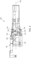
- FIGS. 2 which illustrates a part of the intraoral scanner 100 with some of the components of the intra-oral scanner removed and depicting a lens assembly 122 and a drive assembly 132 operatively engaged with the lens assembly arranged inside a housing of the intra-oral scanner according to an embodiment.
- the lens assembly 122 is arranged inside a frame 130 of the scanner 100 and operatively coupled to a drive assembly 132 of the scanner 100 is shown.
- the drive assembly 132 is supported/mounted on the frame 130 by using suitable brackets. As shown in FIGS.
- the lens assembly 122 is mounted on at least one rail such as a pair of rails 134, 136 arranged inside the frame 130 and is adapted to move linearly back and forth between a first extreme position and a second extreme position along at least a part of respective lengths of the rails 134, 136. It may be appreciated that a translation axis (138, Fig. 4 ) of the lens assembly 122 is substantially parallel to the optical axis 126.
- the rails for example, a first rail 134 and a second rail 136, are arranged spaced apart from each other and are supported by a supporting mechanism within the frame 130.
- the lens assembly 122 includes a lens housing 140 adapted to house and support the lens 124 and is movably arranged on the rails 134, 136.
- the lens 124 is attached, e.g. adhesively coupled, to the lens housing 140 and is arranged such that the lens 124 is aligned to optical axis (126, Fig. 1-3 ).
- the lens assembly 122 may include a magnetic encoder to determine a position of the lens assembly 122 relative to rails 134, 136, the determined position may be associated with a focal plane and used to generate 3D digital representation of dental object from the oral cavity.
- the lens housing 140 may include a ring structure 142 to house and support the lens 124, and a pair of brackets, for example, a first bracket 144 and a second bracket 146, attached to the ring structure 142 and slidably supported on the rails 134, 136.
- the first bracket 144 and the second bracket 146 are supported on the first rail 134 and the second rail 136 respectively, and extend from the ring structure 142 in a direction, such as radial direction.
- the brackets 144, 146 may also be substantially parallel to a central longitudinal axis of the ring structure 142.
- a length of the two brackets may be equal or different with one bracket longer than the other, such as the first bracket 144 being greater than a length of the second bracket 146.
- Each of the brackets 144, 146 may include substantially semicircular cross-section when looking from a front of the lens housing 140.
- the first bracket 144 includes a first longitudinal end (148, Fig. 5 ) attached to the ring structure 142 and a second longitudinal end (150, Fig. 5 ) arranged away from the ring structure 142 and defines a free end of the first bracket 144.
- the second longitudinal end 150 is arranged proximate to the drive assembly 132 and may be operatively coupled to the drive assembly 132.
- the first bracket 144, the second bracket 146, and the ring structure 142 may be constructed as one part.
- the drive assembly 132 includes a drive 152, for example, an electric motor, having a drive shaft 154 (i.e., shaft 154) operatively engaged with the first bracket 144 (i.e., the lens housing 140).
- the first bracket 144 is engaged with the drive 152 such that a rotation of the shaft 154 around its rotation axis 156 causes a translation movement of the lens housing 140 along the translation axis 138 disposed parallel to the optical axis 126 of the lens system 106.
- the rotation of the shaft 154 about the rotation axis 156 causes a back-and-forth movement of the lens housing 140 (i.e., the lens assembly 122) between the first extreme position and the second extreme position.
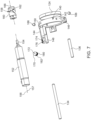
- a length of the shaft is along the rotation axis 156 and coincides with a central longitudinal axis 157 of the shaft 154. Further, the longitudinal axis (157, Fig. 7 ) of the shaft 154 is parallel to the optical axis 126.
- the drive assembly 132 includes a guide 158 arranged or defined continuously along an outer circumferential surface of an end part 160 of the shaft 154.
- the end part 160 is a separate component and is removably attached, as attached for example by a pin-locking mechanism, at an end of the shaft 154 and is arranged coaxially to the shaft 154.
- the end part 160 may be an integral portion of the shaft 154, and the guide 158 is defined along an outer circumferential surface of the shaft 154.
- the end part 160 is adapted to rotate along the shaft 154 around the rotational axis 156.
- the guide 158 is a groove 162 extending continuously along the outer circumferential surface of the end part 160.
- the guide 158 is a female guide and defines a closed path on the outer circumferential surface of the end part 160.
- the groove 162 is defined along the outer circumference surface such that the closed path of the groove 162 is arranged at an angle that is greater than 0 degrees and less than 90 degrees relative to the rotation axis 156. Accordingly, the closed path of the groove 162, and hence the guide 158, is non-parallel to a central longitudinal axis 166 of the end part 160, and hence is non-parallel to the rotation axis 156.
- the guide 158 is defined by the closed path such that a 2D projection of the closed path is non-parallel to the rotation axis 156.
- the groove 162 extends in an elliptical manner along the outer circumferential surface of the end part 160 such that a plane of the ellipse having both major axis and minor axis are at an angle relative to the rotation axis 156 and the central axis 166 of the end part 160.
- the guide 158, and hence the groove 162 follows a path of a sinusoidal curve around the outer circumferential surface of the end part 160.
- the guide 158 extends continuously to form a closed sinusoidal curve around the circumferential surface of the shaft 154 or the end part 160 of the shaft 154.
- the groove 162 is V-shaped groove (as best shown in FIG. 10 ).
- distance of the linear movement of the lens housing 140 (i.e., lens assembly 122) between the first extreme position and second extreme position corresponds to a length of the closed path of the guide 158 around the circumferential surface of the shaft (e.g. end part 160) along which the coupling member travels from a start point to end point of the closed path.
- the distance of the linear movement of the lens housing 140 is lesser than half the length of the closed path guide 158 around the circumferential surface of the shaft (e.g. end part 160).
- the distance of the linear movement of the lens housing 140 in one direction during the back-and-forth movement equals to an axial distance between the two most distant points on the guide that is located at the circumferential surface of the shaft.
- the axial distance may be defined along the rotational axis of the shaft.
- guide 158 is described as the closed path, it may be envisioned that guide may include an open path.
- the lens housing 140 i.e., the lens assembly 122
- the lens housing 140 is moved back and forth by rotating the shaft 154, and hence the end part 160, in both directions.
- this may be performed by configuring the motor to change rotational direction of the shaft to allow back and forth movement of the lens housing.
- this may be performed by having two motors, one motor configured to rotate the shaft in a first rotational direction and another motor configured to rotate the shaft in a second rotational direction opposite to the first rotational direction to allow back and forth movement of the lens housing.
- the scanner 100 includes a coupling element 170 as a male part for operatively engaging the end part 160 with the first bracket 144 (i.e., lens housing 140).
- the coupling element 170 is adapted/arranged to move along the guide 158 in response to the rotation of the guide 158, and hence the end part 160, to enable the translation movement of the lens housing 140 along the translation axis 138.
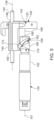
- the coupling element 170 is a spherical ball 172 arranged partially inside the guide 158 and partially inside a gap 174 defined by an attachment part 176 extending from the first bracket 144, as best shown in FIG. 6 . As best shown in FIGS.
- the attachment part 176 is arranged proximate to the second longitudinal end 150 of the first bracket 144 and extends radially outwardly/inwardly from an outer surface of the first bracket 144. As best shown in FIG. 8 , the attachment part 176 is in the form a hollow portion extending inwardly from an outer surface of the first bracket 144 and defining a free space (i.e., the gap 174) therebetween to receive a part of the coupling element 170, thereby supporting the coupling element 170.
- the attachment part 176 may include a plurality of protrusions arrayed circularly and encircling a free space to define the gap 174 therebetween for receiving a part of the coupling element 170. In such a case, the protrusions are arranged spaced apart from each other and extend outwardly from the outer surface of the first bracket 144.
- the coupling element 170 exerts a force on the attachment part 176 as the coupling element 170 travels along the guide 158 to enable the translational movement of the lens assembly 122 (i.e., the lens housing 140) along the translation axis 138 between the first extreme position and the second extreme position.
- the coupling element 170 is contemplated as the spherical ball 172, it may be envisioned that that the coupling element 170 may be a cylindrical pin, or having any other geometrical shape that is designed to slidably engage with the guide. It may be appreciated that a height of the attachment part 176 and a width of the gap 174 are selected such that a portion of the coupling element 170 is arranged inside the gap 174.
- the guide 158 is shown and contemplated as a female part and the coupling element 170 is shown and contemplated as a male part, it may be appreciated that the guide 158 may be a male part, for example a protruded structure, and a coupling element 170 may be a female part, for example, a slot in which the protruded structure extends.
- lubrication is provided at an interface between the coupling element 170 and the guide 158.
- the lens assembly 122 includes a biasing member 180, for example, a spring 182 (best shown in FIGS. 6 and 7 ).
- the spring 182 is configured to apply spring force to keep a part of the coupling element 170 engaged with the guide 158 (i.e., inside the groove 162). Accordingly, the spring 182 facilitates in maintaining the engagement of the coupling element 170 with the guide 158 as coupling element 170 moves along the path defined by the guide 158.
- the spring 182 is arranged inside the gap 174 defined by the attachment part 176 such that spring 182 is arranged between the outer surface of the first bracket 144 (i.e., the lens housing 140) and the coupling element 170, and exerts a biasing force towards the end part 160 (i.e., guide 158) of the shaft 154 to retain the coupling element 170 engaged with the guide 158.
- an end of the spring 182 is fixedly attached with the first bracket 144, and hence the lens housing 140, and other end of the spring 182 is engaged with the coupling element 170.
- the coupling element 170 rests on the spring 182 and compresses the spring 182. Accordingly, spring 182 exerts a force towards the guide 158 and the lens housing 140 (i.e., first bracket 144) in an axial direction. Also, the spring 182 is configured to transfer a lateral force between the coupling element 170 and the lens housing 140 to enable the linear movement of lens housing 140 between the first extreme position and the second extreme position. Further, the spring 182 and the attachment part 176 are disposed such that a longitudinal axis 184 of the spring 182 and the optical axis 126 are arranged in different plane, and therefore, the longitudinal axis 184 and optical axis 126 are arranged separated from each other.
- the spring 182 is arranged such that the longitudinal axis 184 of the spring is arranged orthogonal (i.e., normal) to the optical axis 126. Also, the longitudinal axis 184 is substantially perpendicular to the rotation axis 156. Also, the longitudinal axis 184 is substantially normal to the first rail 134. It may be appreciated that a stiffness of the spring 182 is selected such that the connection between the coupling element 170 (i.e., ball 172) and the guide 158 (i.e., groove 162) is a backlash free connection.
- magnets are provided in the lens housing 140 in the immediate vicinity of the first and second rails 134, 136, which in an embodiment, are made of ferromagnetic material.
- a first magnet 186 is removably or permanently arranged inside the lens housing 140 and is disposed proximate to the first end 148 of the first bracket 144 and the first rail 134
- a second magnet 188 is removably or permanently arranged inside the lens housing 140 and extends inside the second bracket 146 and proximate to the second rail 136.
- both the rails 134, 136 are made of ferromagnetic material to enable a magnetic coupling of the magnets 186, 188 with respective rails 134, 136.
- the magnetic flux density of the one or more of the magnets 186, 188 is between 0.1 Tesla and 5 Tesla depending on the size and the weight of the lens assembly 122.
- first and second brackets 144, 146 are arranged relative to the rails 134, 136 so as to reduce contact area between the first and second brackets 144, 146 and the associated rails 134, 136.
- first and second brackets 144, 146 and the rails 134, 136 are arranged relative to each other such that line contacts or point contacts exist between the first and second brackets 144, 146 and the rails 134, 136.
- the lens housing 140 i.e., the first bracket 144
- the lens housing 140 i.e., the second bracket 146 interfaces at one contact surface with the second rail 136.
- suitable lubrication is provided between the rails 134, 136 and the brackets 144, 146.
- the lens assembly 122 For moving focal plane of the lens 124 along the optical axis 126, the lens assembly 122 is moved linearly and back and forth between the first extreme position and the second extreme position along the translation axis. In the first extreme position, the lens 124 is arranged proximate to the illumination module 102 relative to the second extreme position.
- the drive 152 For moving the lens assembly 122 (i.e., lens housing 140 along with the lens 124), the drive 152 is powered, causing the rotation of the drive shaft 154 about its rotation axis. 156
- the end part 160 also rotates about the rotation axis 156.
- the ball 172 i.e., coupling element 170
- the ball 172 moves along the closed path defined by the groove 162 in response to the rotation of the end part 160.
- the ball 172 moves/translates in a first direction (i.e., forward direction) towards the drive 152 during one half of each rotation of the end part 160 about the rotation axis 156, and moves/translates in a second direction (i.e., a rearward direction) away from the drive 152 during remaining half of the rotation of the end part 160, or vice versa, where the first direction is away from the drive, and the second direction is towards the drive.
- a first direction i.e., forward direction
- a second direction i.e., a rearward direction
- the ball 172 exerts a force on the attachment part 176, and hence the lens housing 140, causing the back-and-forth movement of the lens assembly 122 relative to the rails 134, 136 along the translation axis 138. Accordingly, the lens assembly 122 moves towards the one extreme position when the ball 172 moves in the first direction, and the lens assembly 122 moves towards another extreme position opposite to the one extreme position when the ball 172 moves in the second direction. In this manner, by moving the lens assembly 122 back and forth along the translation axis 138, the focal plane of the lens system 106, and hence the scanner 100 can be changed.
- the scanner 100 may be orientated at various orientation and the focal plane of the scanner 100 is changed by moving the lens assembly 122 at each orientation to take a stack of 2D images for each orientation. These 2D images are stitched together by applying known techniques such as Iterative Closest Point (ICP) to obtain three-dimensional digital representation of the dental object 200.
- ICP Iterative Closest Point
Landscapes
- Health & Medical Sciences (AREA)
- Physics & Mathematics (AREA)
- Life Sciences & Earth Sciences (AREA)
- Oral & Maxillofacial Surgery (AREA)
- Dentistry (AREA)
- Animal Behavior & Ethology (AREA)
- General Health & Medical Sciences (AREA)
- Public Health (AREA)
- Veterinary Medicine (AREA)
- Optics & Photonics (AREA)
- Epidemiology (AREA)
- Engineering & Computer Science (AREA)
- Computer Vision & Pattern Recognition (AREA)
- General Physics & Mathematics (AREA)
- Audiology, Speech & Language Pathology (AREA)
- Biophysics (AREA)
- Pathology (AREA)
- Biomedical Technology (AREA)
- Heart & Thoracic Surgery (AREA)
- Medical Informatics (AREA)
- Molecular Biology (AREA)
- Surgery (AREA)
- Endoscopes (AREA)
- Dental Tools And Instruments Or Auxiliary Dental Instruments (AREA)
Claims (15)
- Intraoraler tragbarer optischer 3D-Scanner (100), umfassend:ein Beleuchtungsmodul (102), das dazu konfiguriert ist, ein Beleuchtungssignal zum Beleuchten eines Dentalobjekts (200) zu erzeugen;einen Bildsensor (104), der dazu konfiguriert ist, als Reaktion auf die Beleuchtung des Dentalobjekts Daten zu erhalten, wobei die Daten dazu konfiguriert sind, zum Erzeugen eines 3D-Dentalmodells des Dentalobjekts verwendet zu werden;ein Linsengehäuse (140), das eine optische Linse (124) umfasst, die dazu konfiguriert ist, das Beleuchtungssignal auf das Dentalobjekt zu richten;einen Antrieb (152), der eine Welle (154) umfasst, die dazu konfiguriert ist, sich um eine Rotationsachse (156) zu drehen;eine Führung (158), die sich kontinuierlich entlang mindestens eines Teils einer Länge der Welle erstreckt, gekennzeichnet durcheine Feder (182), die zwischen dem Linsengehäuse und der Führung angeordnet ist und dazu konfiguriert ist, eine Federkraft in Richtung der Führung auszuüben.
- Intraoraler tragbarer optischer 3D-Scanner nach Anspruch 1, wobei die Welle ein Endteil (162) umfasst, das koaxial mit dem Rest der Welle verbunden ist, und die Führung an dem Endteil angeordnet ist.
- Intraoraler tragbarer optischer 3D-Scanner nach einem der vorstehenden Ansprüche, wobei sich die Führung kontinuierlich erstreckt, um eine geschlossene Sinuskurve um die Umfangsfläche der Welle zu bilden.
- Intraoraler tragbarer optischer 3D-Scanner nach einem der vorstehenden Ansprüche, wobei die Welle dazu konfiguriert ist, sich um die Rotationsachse zu drehen, um eine lineare Bewegung des Linsengehäuses entlang einer Translationsachse (138) zu erzeugen, und wobei die lineare Bewegung eine Hin- und Herbewegung zwischen einer ersten Extremposition und einer zweiten Extremposition umfasst.
- Intraoraler tragbarer optischer 3D-Scanner nach einem der vorstehenden Ansprüche, wobei das Linsengehäuse ein Befestigungsteil (176) umfasst, wo die Feder fest an dem Linsengehäuse befestigt ist.
- Intraoraler tragbarer optischer 3D-Scanner nach einem der vorstehenden Ansprüche, wobei das Befestigungsteil eine Vielzahl von Vorsprüngen umfasst, wobei die Vielzahl von Vorsprüngen mindestens teilweise einen freien Raum umgibt, wobei die Feder in dem freien Raum angeordnet ist und die Feder mindestens teilweise von der Vielzahl von Vorsprüngen umgeben ist.
- Intraoraler tragbarer optischer 3D-Scanner nach einem der vorstehenden Ansprüche, der weiter ein Kopplungselement (170) umfasst, das die Führung funktional mit der Feder verbindet.
- Intraoraler tragbarer optischer 3D-Scanner nach Anspruch 7, wobei die Feder eine Kraft ausübt, die dazu konfiguriert ist, eine Verbindung zwischen dem Kopplungselement und dem Linsengehäuse aufrechtzuerhalten.
- Intraoraler tragbarer optischer 3D-Scanner nach einem der Ansprüche 7-8, wobeidie Welle dazu konfiguriert ist, sich um die Rotationsachse zu drehen;das Koppplungselement dazu konfiguriert ist, sich als Reaktion auf die Drehung der Welle entlang der Führung zu bewegen; unddas Linsengehäuse dazu konfiguriert ist, sich als Reaktion auf die Bewegung des Kopplungselements entlang der Führung linear zwischen der ersten Extremposition und der zweiten Extremposition entlang einer Translationsachse (138) zu bewegen.
- Intraoraler tragbarer optischer 3D-Scanner nach einem der Ansprüche 7-9, wobei die Feder eine Kraft ausübt, die dazu konfiguriert ist, eine Verbindung zwischen dem Kopplungselement und der Führung aufrechtzuerhalten.
- Intraoraler tragbarer optischer 3D-Scanner nach einem der Ansprüche 7-10, wobei mindestens ein Teil des Kopplungselements in dem Befestigungsteil angeordnet ist.
- Intraoraler tragbarer optischer 3D-Scanner nach einem der Ansprüche 7-11, wobei die Führung eines von einem männlichen Teil oder einem weiblichen Teil ist und das Kopplungselement ein anderes des weiblichen Teils oder männlichen Teils ist.
- Intraoraler tragbarer optischer 3D-Scanner nach einem der vorstehenden Ansprüche, wobei das Linsengehäuse dazu konfiguriert ist, sich entlang einer oder mehrerer Schienen zu bewegen.
- Intraoraler tragbarer optischer 3D-Scanner nach Anspruch 13, wobei die eine oder mehreren Schienen ferromagnetisch sind und neben der einen oder mehreren Schienen angeordnet sind.
- Intraoraler tragbarer optischer 3D-Scanner nach einem der Ansprüche 13 oder 14, wobeidas Linsengehäuse dazu konfiguriert ist, entlang mindestens zweier Schienen zu gleiten; unddas Linsengehäuse an zwei Kontaktflächen an mindestens einer Schiene der mindestens zwei Schienen anschließt und das Linsengehäuse an einer Kontaktfläche an mindestens einer Schiene der mindestens zwei Schienen anschließt.
Priority Applications (1)
| Application Number | Priority Date | Filing Date | Title |
|---|---|---|---|
| EP24197332.0A EP4502535A3 (de) | 2021-12-22 | 2022-12-15 | Scanner mit neuartigem linsenantriebsmechanismus |
Applications Claiming Priority (1)
| Application Number | Priority Date | Filing Date | Title |
|---|---|---|---|
| EP21216829 | 2021-12-22 |
Related Child Applications (3)
| Application Number | Title | Priority Date | Filing Date |
|---|---|---|---|
| EP24197332.0A Division EP4502535A3 (de) | 2021-12-22 | 2022-12-15 | Scanner mit neuartigem linsenantriebsmechanismus |
| EP24197332.0A Previously-Filed-Application EP4502535A3 (de) | 2021-12-22 | 2022-12-15 | Scanner mit neuartigem linsenantriebsmechanismus |
| EP24197332.0A Division-Into EP4502535A3 (de) | 2021-12-22 | 2022-12-15 | Scanner mit neuartigem linsenantriebsmechanismus |
Publications (2)
| Publication Number | Publication Date |
|---|---|
| EP4201372A1 EP4201372A1 (de) | 2023-06-28 |
| EP4201372B1 true EP4201372B1 (de) | 2024-10-09 |
Family
ID=79021005
Family Applications (2)
| Application Number | Title | Priority Date | Filing Date |
|---|---|---|---|
| EP22213691.3A Active EP4201372B1 (de) | 2021-12-22 | 2022-12-15 | Scanner mit neuartigem linsenantriebsmechanismus |
| EP24197332.0A Pending EP4502535A3 (de) | 2021-12-22 | 2022-12-15 | Scanner mit neuartigem linsenantriebsmechanismus |
Family Applications After (1)
| Application Number | Title | Priority Date | Filing Date |
|---|---|---|---|
| EP24197332.0A Pending EP4502535A3 (de) | 2021-12-22 | 2022-12-15 | Scanner mit neuartigem linsenantriebsmechanismus |
Country Status (4)
| Country | Link |
|---|---|
| US (1) | US20230190425A1 (de) |
| EP (2) | EP4201372B1 (de) |
| CN (1) | CN116327116A (de) |
| ES (1) | ES2999010T3 (de) |
Family Cites Families (12)
| Publication number | Priority date | Publication date | Assignee | Title |
|---|---|---|---|---|
| US2362603A (en) * | 1943-08-26 | 1944-11-14 | Eastman Kodak Co | Focusing lens mount |
| US4585313A (en) * | 1982-12-14 | 1986-04-29 | West Electric Company Ltd. | Lens drive device and optical lens assembly utilizing the same |
| US4935635A (en) * | 1988-12-09 | 1990-06-19 | Harra Dale G O | System for measuring objects in three dimensions |
| JPH0727099B2 (ja) * | 1990-10-02 | 1995-03-29 | キヤノン株式会社 | レンズ駆動装置を有する光学機器 |
| DE4218219C2 (de) * | 1992-06-03 | 1998-05-07 | Geyer Medizin Und Fertigungste | Vorrichtung zum berührungslosen Vermessen eines schlecht zugänglichen, dreidimensionalen medizinischen oder zahntechnischen Objektes |
| US6546272B1 (en) * | 1999-06-24 | 2003-04-08 | Mackinnon Nicholas B. | Apparatus for in vivo imaging of the respiratory tract and other internal organs |
| JP4857241B2 (ja) * | 2006-10-31 | 2012-01-18 | 有限会社メーコー精機 | 機械装置及びその駆動体保持機構 |
| DE102007005726B4 (de) * | 2007-01-31 | 2010-05-12 | Sirona Dental Systems Gmbh | Vorrichtung und Verfahren zur optischen 3D-Vermessung |
| JP5241372B2 (ja) * | 2008-08-01 | 2013-07-17 | キヤノン株式会社 | レンズ鏡筒 |
| KR101533341B1 (ko) * | 2014-03-04 | 2015-07-03 | 이태경 | 휴대형 스캐너 |
| JP6786424B2 (ja) * | 2017-03-13 | 2020-11-18 | 株式会社モリタ製作所 | 三次元スキャナ |
| EP3628271B1 (de) * | 2018-09-27 | 2021-07-21 | Sirona Dental Systems GmbH | Vorrichtung zur veränderung des brennpunktes eines optischen systems in einem dentalen 3d-scanner sowie ein dentaler 3d-scanner |
-
2022
- 2022-12-15 EP EP22213691.3A patent/EP4201372B1/de active Active
- 2022-12-15 CN CN202211615166.5A patent/CN116327116A/zh active Pending
- 2022-12-15 EP EP24197332.0A patent/EP4502535A3/de active Pending
- 2022-12-15 ES ES22213691T patent/ES2999010T3/es active Active
- 2022-12-16 US US18/067,047 patent/US20230190425A1/en active Pending
Also Published As
| Publication number | Publication date |
|---|---|
| EP4502535A2 (de) | 2025-02-05 |
| EP4201372A1 (de) | 2023-06-28 |
| EP4502535A3 (de) | 2025-03-12 |
| ES2999010T3 (en) | 2025-02-24 |
| CN116327116A (zh) | 2023-06-27 |
| US20230190425A1 (en) | 2023-06-22 |
Similar Documents
| Publication | Publication Date | Title |
|---|---|---|
| US12097009B2 (en) | Compact intraoral 3D scanner | |
| JP5654583B2 (ja) | 焦点操作装置 | |
| CN103826527B (zh) | 一次性内窥镜 | |
| US7099732B2 (en) | Sanitary sleeve or tip for intra-oral three-dimensional camera | |
| KR101533756B1 (ko) | 구강 내 고정형 3차원 구강 스캐너 | |
| EP3644893A1 (de) | Automatischer intraoraler 3d-scanner mit lichtfolienaktiver triangulation | |
| KR102779552B1 (ko) | 치과용 3d 스캐너에서 광학 시스템의 초점을 변경하기 위한 장치 및 치과용 3d 스캐너 | |
| EP4201372B1 (de) | Scanner mit neuartigem linsenantriebsmechanismus | |
| WO2023036876A1 (en) | Compact intraoral 3d-scanner and a method of optimizing it | |
| KR102551332B1 (ko) | 구강 스캐너용 캘리브레이션 장치 | |
| KR102847763B1 (ko) | 단일 카메라로 스테레오 광학계를 구성한 3차원 이미지 구강 스캐너 | |
| KR20220118690A (ko) | 구강 스캐너용 캘리브레이션 장치 | |
| JP7741840B2 (ja) | リニアモータ、およびそれを用いた医療用診療装置 | |
| CN119486682A (zh) | 具有卫生外壳的口内扫描仪 | |
| WO2025191493A1 (en) | Device for estimating the three-dimensional structure of teeth | |
| KR20250162866A (ko) | 구강외 스캐너 시스템 | |
| JP2008099866A (ja) | 歯列撮像装置 |
Legal Events
| Date | Code | Title | Description |
|---|---|---|---|
| PUAI | Public reference made under article 153(3) epc to a published international application that has entered the european phase |
Free format text: ORIGINAL CODE: 0009012 |
|
| STAA | Information on the status of an ep patent application or granted ep patent |
Free format text: STATUS: THE APPLICATION HAS BEEN PUBLISHED |
|
| AK | Designated contracting states |
Kind code of ref document: A1 Designated state(s): AL AT BE BG CH CY CZ DE DK EE ES FI FR GB GR HR HU IE IS IT LI LT LU LV MC ME MK MT NL NO PL PT RO RS SE SI SK SM TR |
|
| STAA | Information on the status of an ep patent application or granted ep patent |
Free format text: STATUS: REQUEST FOR EXAMINATION WAS MADE |
|
| 17P | Request for examination filed |
Effective date: 20231217 |
|
| RBV | Designated contracting states (corrected) |
Designated state(s): AL AT BE BG CH CY CZ DE DK EE ES FI FR GB GR HR HU IE IS IT LI LT LU LV MC ME MK MT NL NO PL PT RO RS SE SI SK SM TR |
|
| GRAP | Despatch of communication of intention to grant a patent |
Free format text: ORIGINAL CODE: EPIDOSNIGR1 |
|
| STAA | Information on the status of an ep patent application or granted ep patent |
Free format text: STATUS: GRANT OF PATENT IS INTENDED |
|
| INTG | Intention to grant announced |
Effective date: 20240430 |
|
| GRAS | Grant fee paid |
Free format text: ORIGINAL CODE: EPIDOSNIGR3 |
|
| GRAA | (expected) grant |
Free format text: ORIGINAL CODE: 0009210 |
|
| STAA | Information on the status of an ep patent application or granted ep patent |
Free format text: STATUS: THE PATENT HAS BEEN GRANTED |
|
| P01 | Opt-out of the competence of the unified patent court (upc) registered |
Free format text: CASE NUMBER: APP_48487/2024 Effective date: 20240823 |
|
| AK | Designated contracting states |
Kind code of ref document: B1 Designated state(s): AL AT BE BG CH CY CZ DE DK EE ES FI FR GB GR HR HU IE IS IT LI LT LU LV MC ME MK MT NL NO PL PT RO RS SE SI SK SM TR |
|
| REG | Reference to a national code |
Ref country code: CH Ref legal event code: EP |
|
| REG | Reference to a national code |
Ref country code: DE Ref legal event code: R096 Ref document number: 602022006683 Country of ref document: DE |
|
| REG | Reference to a national code |
Ref country code: IE Ref legal event code: FG4D |
|
| REG | Reference to a national code |
Ref country code: LT Ref legal event code: MG9D |
|
| REG | Reference to a national code |
Ref country code: NL Ref legal event code: MP Effective date: 20241009 |
|
| REG | Reference to a national code |
Ref country code: ES Ref legal event code: FG2A Ref document number: 2999010 Country of ref document: ES Kind code of ref document: T3 Effective date: 20250224 |
|
| REG | Reference to a national code |
Ref country code: AT Ref legal event code: MK05 Ref document number: 1729742 Country of ref document: AT Kind code of ref document: T Effective date: 20241009 |
|
| PG25 | Lapsed in a contracting state [announced via postgrant information from national office to epo] |
Ref country code: NL Free format text: LAPSE BECAUSE OF FAILURE TO SUBMIT A TRANSLATION OF THE DESCRIPTION OR TO PAY THE FEE WITHIN THE PRESCRIBED TIME-LIMIT Effective date: 20241009 |
|
| PG25 | Lapsed in a contracting state [announced via postgrant information from national office to epo] |
Ref country code: NL Free format text: LAPSE BECAUSE OF FAILURE TO SUBMIT A TRANSLATION OF THE DESCRIPTION OR TO PAY THE FEE WITHIN THE PRESCRIBED TIME-LIMIT Effective date: 20241009 |
|
| PG25 | Lapsed in a contracting state [announced via postgrant information from national office to epo] |
Ref country code: IS Free format text: LAPSE BECAUSE OF FAILURE TO SUBMIT A TRANSLATION OF THE DESCRIPTION OR TO PAY THE FEE WITHIN THE PRESCRIBED TIME-LIMIT Effective date: 20250209 Ref country code: PT Free format text: LAPSE BECAUSE OF FAILURE TO SUBMIT A TRANSLATION OF THE DESCRIPTION OR TO PAY THE FEE WITHIN THE PRESCRIBED TIME-LIMIT Effective date: 20250210 Ref country code: HR Free format text: LAPSE BECAUSE OF FAILURE TO SUBMIT A TRANSLATION OF THE DESCRIPTION OR TO PAY THE FEE WITHIN THE PRESCRIBED TIME-LIMIT Effective date: 20241009 |
|
| PG25 | Lapsed in a contracting state [announced via postgrant information from national office to epo] |
Ref country code: FI Free format text: LAPSE BECAUSE OF FAILURE TO SUBMIT A TRANSLATION OF THE DESCRIPTION OR TO PAY THE FEE WITHIN THE PRESCRIBED TIME-LIMIT Effective date: 20241009 |
|
| PG25 | Lapsed in a contracting state [announced via postgrant information from national office to epo] |
Ref country code: BG Free format text: LAPSE BECAUSE OF FAILURE TO SUBMIT A TRANSLATION OF THE DESCRIPTION OR TO PAY THE FEE WITHIN THE PRESCRIBED TIME-LIMIT Effective date: 20241009 |
|
| PG25 | Lapsed in a contracting state [announced via postgrant information from national office to epo] |
Ref country code: NO Free format text: LAPSE BECAUSE OF FAILURE TO SUBMIT A TRANSLATION OF THE DESCRIPTION OR TO PAY THE FEE WITHIN THE PRESCRIBED TIME-LIMIT Effective date: 20250109 |
|
| PG25 | Lapsed in a contracting state [announced via postgrant information from national office to epo] |
Ref country code: LV Free format text: LAPSE BECAUSE OF FAILURE TO SUBMIT A TRANSLATION OF THE DESCRIPTION OR TO PAY THE FEE WITHIN THE PRESCRIBED TIME-LIMIT Effective date: 20241009 Ref country code: GR Free format text: LAPSE BECAUSE OF FAILURE TO SUBMIT A TRANSLATION OF THE DESCRIPTION OR TO PAY THE FEE WITHIN THE PRESCRIBED TIME-LIMIT Effective date: 20250110 Ref country code: AT Free format text: LAPSE BECAUSE OF FAILURE TO SUBMIT A TRANSLATION OF THE DESCRIPTION OR TO PAY THE FEE WITHIN THE PRESCRIBED TIME-LIMIT Effective date: 20241009 |
|
| PG25 | Lapsed in a contracting state [announced via postgrant information from national office to epo] |
Ref country code: PL Free format text: LAPSE BECAUSE OF FAILURE TO SUBMIT A TRANSLATION OF THE DESCRIPTION OR TO PAY THE FEE WITHIN THE PRESCRIBED TIME-LIMIT Effective date: 20241009 |
|
| PG25 | Lapsed in a contracting state [announced via postgrant information from national office to epo] |
Ref country code: IT Free format text: LAPSE BECAUSE OF NON-PAYMENT OF DUE FEES Effective date: 20241215 |
|
| PG25 | Lapsed in a contracting state [announced via postgrant information from national office to epo] |
Ref country code: RS Free format text: LAPSE BECAUSE OF FAILURE TO SUBMIT A TRANSLATION OF THE DESCRIPTION OR TO PAY THE FEE WITHIN THE PRESCRIBED TIME-LIMIT Effective date: 20250109 |
|
| PG25 | Lapsed in a contracting state [announced via postgrant information from national office to epo] |
Ref country code: SM Free format text: LAPSE BECAUSE OF FAILURE TO SUBMIT A TRANSLATION OF THE DESCRIPTION OR TO PAY THE FEE WITHIN THE PRESCRIBED TIME-LIMIT Effective date: 20241009 |
|
| PG25 | Lapsed in a contracting state [announced via postgrant information from national office to epo] |
Ref country code: MC Free format text: LAPSE BECAUSE OF FAILURE TO SUBMIT A TRANSLATION OF THE DESCRIPTION OR TO PAY THE FEE WITHIN THE PRESCRIBED TIME-LIMIT Effective date: 20241009 |
|
| PG25 | Lapsed in a contracting state [announced via postgrant information from national office to epo] |
Ref country code: DK Free format text: LAPSE BECAUSE OF FAILURE TO SUBMIT A TRANSLATION OF THE DESCRIPTION OR TO PAY THE FEE WITHIN THE PRESCRIBED TIME-LIMIT Effective date: 20241009 |
|
| REG | Reference to a national code |
Ref country code: DE Ref legal event code: R097 Ref document number: 602022006683 Country of ref document: DE |
|
| PG25 | Lapsed in a contracting state [announced via postgrant information from national office to epo] |
Ref country code: EE Free format text: LAPSE BECAUSE OF FAILURE TO SUBMIT A TRANSLATION OF THE DESCRIPTION OR TO PAY THE FEE WITHIN THE PRESCRIBED TIME-LIMIT Effective date: 20241009 |
|
| PG25 | Lapsed in a contracting state [announced via postgrant information from national office to epo] |
Ref country code: RO Free format text: LAPSE BECAUSE OF FAILURE TO SUBMIT A TRANSLATION OF THE DESCRIPTION OR TO PAY THE FEE WITHIN THE PRESCRIBED TIME-LIMIT Effective date: 20241009 |
|
| PG25 | Lapsed in a contracting state [announced via postgrant information from national office to epo] |
Ref country code: SK Free format text: LAPSE BECAUSE OF FAILURE TO SUBMIT A TRANSLATION OF THE DESCRIPTION OR TO PAY THE FEE WITHIN THE PRESCRIBED TIME-LIMIT Effective date: 20241009 |
|
| PG25 | Lapsed in a contracting state [announced via postgrant information from national office to epo] |
Ref country code: CZ Free format text: LAPSE BECAUSE OF FAILURE TO SUBMIT A TRANSLATION OF THE DESCRIPTION OR TO PAY THE FEE WITHIN THE PRESCRIBED TIME-LIMIT Effective date: 20241009 |
|
| PLBE | No opposition filed within time limit |
Free format text: ORIGINAL CODE: 0009261 |
|
| STAA | Information on the status of an ep patent application or granted ep patent |
Free format text: STATUS: NO OPPOSITION FILED WITHIN TIME LIMIT |
|
| PG25 | Lapsed in a contracting state [announced via postgrant information from national office to epo] |
Ref country code: LU Free format text: LAPSE BECAUSE OF NON-PAYMENT OF DUE FEES Effective date: 20241215 |
|
| PG25 | Lapsed in a contracting state [announced via postgrant information from national office to epo] |
Ref country code: SE Free format text: LAPSE BECAUSE OF FAILURE TO SUBMIT A TRANSLATION OF THE DESCRIPTION OR TO PAY THE FEE WITHIN THE PRESCRIBED TIME-LIMIT Effective date: 20241009 |
|
| 26N | No opposition filed |
Effective date: 20250710 |
|
| REG | Reference to a national code |
Ref country code: BE Ref legal event code: MM Effective date: 20241231 |
|
| PG25 | Lapsed in a contracting state [announced via postgrant information from national office to epo] |
Ref country code: BE Free format text: LAPSE BECAUSE OF NON-PAYMENT OF DUE FEES Effective date: 20241231 |
|
| PG25 | Lapsed in a contracting state [announced via postgrant information from national office to epo] |
Ref country code: IE Free format text: LAPSE BECAUSE OF NON-PAYMENT OF DUE FEES Effective date: 20241215 |
|
| PGFP | Annual fee paid to national office [announced via postgrant information from national office to epo] |
Ref country code: DE Payment date: 20251211 Year of fee payment: 4 |
|
| PG25 | Lapsed in a contracting state [announced via postgrant information from national office to epo] |
Ref country code: IT Free format text: LAPSE BECAUSE OF NON-PAYMENT OF DUE FEES Effective date: 20241215 |
|
| PGRI | Patent reinstated in contracting state [announced from national office to epo] |
Ref country code: IT Effective date: 20241231 |
|
| PGFP | Annual fee paid to national office [announced via postgrant information from national office to epo] |
Ref country code: FR Payment date: 20251229 Year of fee payment: 4 |
|
| PGFP | Annual fee paid to national office [announced via postgrant information from national office to epo] |
Ref country code: ES Payment date: 20260130 Year of fee payment: 4 |
|
| PGFP | Annual fee paid to national office [announced via postgrant information from national office to epo] |
Ref country code: IT Payment date: 20251231 Year of fee payment: 4 |