EP3628271B1 - Vorrichtung zur veränderung des brennpunktes eines optischen systems in einem dentalen 3d-scanner sowie ein dentaler 3d-scanner - Google Patents
Vorrichtung zur veränderung des brennpunktes eines optischen systems in einem dentalen 3d-scanner sowie ein dentaler 3d-scanner Download PDFInfo
- Publication number
- EP3628271B1 EP3628271B1 EP18197051.8A EP18197051A EP3628271B1 EP 3628271 B1 EP3628271 B1 EP 3628271B1 EP 18197051 A EP18197051 A EP 18197051A EP 3628271 B1 EP3628271 B1 EP 3628271B1
- Authority
- EP
- European Patent Office
- Prior art keywords
- lens
- anchor
- unit
- movement
- lens unit
- Prior art date
- Legal status (The legal status is an assumption and is not a legal conclusion. Google has not performed a legal analysis and makes no representation as to the accuracy of the status listed.)
- Active
Links
Images


Classifications
-
- A—HUMAN NECESSITIES
- A61—MEDICAL OR VETERINARY SCIENCE; HYGIENE
- A61C—DENTISTRY; APPARATUS OR METHODS FOR ORAL OR DENTAL HYGIENE
- A61C9/00—Impression cups, i.e. impression trays; Impression methods
- A61C9/004—Means or methods for taking digitized impressions
- A61C9/0046—Data acquisition means or methods
- A61C9/0053—Optical means or methods, e.g. scanning the teeth by a laser or light beam
-
- G—PHYSICS
- G02—OPTICS
- G02B—OPTICAL ELEMENTS, SYSTEMS OR APPARATUS
- G02B7/00—Mountings, adjusting means, or light-tight connections, for optical elements
- G02B7/02—Mountings, adjusting means, or light-tight connections, for optical elements for lenses
- G02B7/04—Mountings, adjusting means, or light-tight connections, for optical elements for lenses with mechanism for focusing or varying magnification
-
- A—HUMAN NECESSITIES
- A61—MEDICAL OR VETERINARY SCIENCE; HYGIENE
- A61B—DIAGNOSIS; SURGERY; IDENTIFICATION
- A61B5/00—Measuring for diagnostic purposes; Identification of persons
- A61B5/0059—Measuring for diagnostic purposes; Identification of persons using light, e.g. diagnosis by transillumination, diascopy, fluorescence
- A61B5/0062—Arrangements for scanning
-
- A—HUMAN NECESSITIES
- A61—MEDICAL OR VETERINARY SCIENCE; HYGIENE
- A61B—DIAGNOSIS; SURGERY; IDENTIFICATION
- A61B5/00—Measuring for diagnostic purposes; Identification of persons
- A61B5/0059—Measuring for diagnostic purposes; Identification of persons using light, e.g. diagnosis by transillumination, diascopy, fluorescence
- A61B5/0082—Measuring for diagnostic purposes; Identification of persons using light, e.g. diagnosis by transillumination, diascopy, fluorescence adapted for particular medical purposes
- A61B5/0088—Measuring for diagnostic purposes; Identification of persons using light, e.g. diagnosis by transillumination, diascopy, fluorescence adapted for particular medical purposes for oral or dental tissue
-
- A—HUMAN NECESSITIES
- A61—MEDICAL OR VETERINARY SCIENCE; HYGIENE
- A61C—DENTISTRY; APPARATUS OR METHODS FOR ORAL OR DENTAL HYGIENE
- A61C9/00—Impression cups, i.e. impression trays; Impression methods
- A61C9/004—Means or methods for taking digitized impressions
- A61C9/0046—Data acquisition means or methods
- A61C9/0053—Optical means or methods, e.g. scanning the teeth by a laser or light beam
- A61C9/0066—Depth determination through adaptive focusing
-
- G—PHYSICS
- G02—OPTICS
- G02B—OPTICAL ELEMENTS, SYSTEMS OR APPARATUS
- G02B27/00—Optical systems or apparatus not provided for by any of the groups G02B1/00 - G02B26/00, G02B30/00
- G02B27/64—Imaging systems using optical elements for stabilisation of the lateral and angular position of the image
- G02B27/646—Imaging systems using optical elements for stabilisation of the lateral and angular position of the image compensating for small deviations, e.g. due to vibration or shake
-
- G—PHYSICS
- G02—OPTICS
- G02B—OPTICAL ELEMENTS, SYSTEMS OR APPARATUS
- G02B7/00—Mountings, adjusting means, or light-tight connections, for optical elements
- G02B7/02—Mountings, adjusting means, or light-tight connections, for optical elements for lenses
- G02B7/04—Mountings, adjusting means, or light-tight connections, for optical elements for lenses with mechanism for focusing or varying magnification
- G02B7/08—Mountings, adjusting means, or light-tight connections, for optical elements for lenses with mechanism for focusing or varying magnification adapted to co-operate with a remote control mechanism
-
- A—HUMAN NECESSITIES
- A61—MEDICAL OR VETERINARY SCIENCE; HYGIENE
- A61B—DIAGNOSIS; SURGERY; IDENTIFICATION
- A61B18/00—Surgical instruments, devices or methods for transferring non-mechanical forms of energy to or from the body
- A61B18/18—Surgical instruments, devices or methods for transferring non-mechanical forms of energy to or from the body by applying electromagnetic radiation, e.g. microwaves
- A61B18/20—Surgical instruments, devices or methods for transferring non-mechanical forms of energy to or from the body by applying electromagnetic radiation, e.g. microwaves using laser
- A61B2018/2035—Beam shaping or redirecting; Optical components therefor
- A61B2018/20351—Scanning mechanisms
- A61B2018/20353—Scanning in three dimensions [3D]
Definitions
- the present invention relates to an apparatus for varying a focal point of an optical system in a dental 3D-scanner.
- the present invention further relates to a dental 3D-scanner.
- 3D-scanners can sometimes also be referred to as tomography scanners
- Such a model can, e.g., form the basis for a computer-aided prosthesis design.
- various handheld devices to be inserted into a patient's mouth as an intraoral 3D-scanner for obtaining in-situ scan data For instance, a camera sensor can be used to gather the respective data. Usually, the camera is manually moved around the upper or lower jaw or a section of interest of the jaws that is subject to reconstruction.
- the scanning and reconstruction can, e.g., be based on fringe projection methods.
- Objects are illuminated with structured patterns of light. These patterns are modulated by the scan object and then recorded as an image with a camera at a known angle with respect to the projections.
- Techniques such as a Fourier transformation can be used to calculate the surface modulations by analyzing the recorded images. Based on these data, it is possible to obtain 3D coordinates of the scan object.
- Different 3D-measurement principles require that a lens of an optical system of the image sensor is moved in order to vary a focal point (or focal plane).
- a focal point or focal plane
- This measurement principle corresponds to the function of a confocal microscope. If the camera is a handheld device, it is important that the lens is moved at sufficient speed so that a relative movement of the camera with respect to the scan object does not affect the measurement accuracy.
- oscillation frequencies of a movable lens in a dental 3D-scanner are on the order of 2-20 Hz.
- EP 2 051 042 B1 relates to a device for tomographically recording objects.
- the device comprises a first grid arranged in an optical axis of a light beam downstream of a source of light which the light beam may be guided through before irradiating an object so that a pattern of the first grid may be projected on the object.
- the device further comprises an optical imaging assembly for imaging the object on a sensor.
- the device comprises a second grid provided in the optical axis of the reflected light beam, the second grid having a pattern matching the first grid, the reflected light beam having the pattern of the first grid being guided through said second grid so that the sensor senses the light beam reflected by the object with a Moiré pattern resulting from overlying the pattern of the first grid and the pattern of the second grid.
- DE10356412A1 discloses a multifocal confocal method and confocal arrangement for less cooperative objects.
- EP2377464A1 discloses 3D imaging using double telecentric optical systems and depth measurement from focus sequence.
- US2018192877A1 discloses a compact confocal dental scanning apparatus.
- vibrations One challenge with current approaches to three-dimensional scanning by means of a movable lens are vibrations.
- the movement of the lens in a handheld scanning device can result in vibrations of the scanning devices. These vibrations can cause a blurring of the gathered data and the reconstructed 3D-scan.
- One approach to compensate such vibrations is to make use of a counterweight. Such a counterweight can be moved at the same speed as the lens but in the opposite direction. This, however, has the drawback that the total mass is increased so that it becomes more difficult to move the lens at an adequate oscillation frequency.
- the present invention faces the problem of improving the image quality of a dental 3D-scanner with a movable lens.
- the present invention aims at reducing vibrations of a handheld scanning device for intraoral application albeit allowing a lightweight construction of the device.
- a high oscillation frequency and a quick reaction of the movable lens is desired to allow for a compensation of manual movements of the handheld device with respect to the scan object.
- a first aspect of the present invention relates to an apparatus for varying a focal point of an optical system in a dental 3D-scanner, comprising:
- the invention relates to a dental 3D-scanner for scanning a three-dimensional scan object, comprising:
- the apparatus of the present invention has a lens unit including the lens and the respective fixation that is movable between a front reversal position and a rear reversal position.
- This movement is guided by means of a guide unit in a direction parallel to an optical axis of the lens (guide axis).
- a distance between the lens and a photodetector of the dental 3D-scanner as well as a projector is varied.
- the distance is increased in the front reversal position.
- a position of a focal point with respect to a scan object is modified. In other words, the scan object is scanned at different depths or in different planes.
- the movement is driven by a drive unit having a linear motor.
- the stator of the linear motor is affixed to the guide unit and the anchor movement is transferred to the lens unit.
- the lens is oscillated at an oscillation frequency while scanning the scan object. The movement of the lens is thereby limited by the distance between the front reversal position and the rear reversal position. It is, however, also possible that the lens is moved by a smaller amplitude.
- the present invention is based on the idea of making use of a linear motor for moving a lens in a dental 3D-scanner.
- the linear motor of the present invention has the advantage that the control of the movement of the lens can be very precise and accurate. It becomes possible to freely choose a reversal point to adapt the movement of the lens to the size and position of a scan object. The position of the lens can be assessed very accurately by means of corresponding sensors. Further, high accelerations of the lens unit are possible so that high oscillation frequencies can be realized. As a result, high quality scans can be generated.
- the drive unit includes a coupling arrangement for coupling a movement of the anchor and the lens unit so that a movement of the anchor in a first direction is transferred to a movement of the lens in a second direction opposite to the first direction.
- the anchor of the linear motor is used as a counterweight to compensate for vibrations caused by the movement of the lens unit.
- this has the advantage that a more lightweight construction can be obtained.
- the timing of the movement of the lens unit and the counterweight is ensured. Since the lens unit is driven by the counterweight, no vibrations can occur. Measurement accuracy is improved and it is ensured that a high-quality three-dimensional image of an object can be generated.
- the coupling arrangement includes a flexible connection element for connecting the anchor and the lens unit to transfer a force from the anchor to the lens unit.
- Said flexible connection element preferably includes a steel strip.
- a steel strip can also be referred to as a steel tape.
- the flexible connection element transforms or transmits the movement of the anchor to a movement of the lens unit in the opposite direction.
- the connection element is preferably flexible in a single direction so that it can be guided around a respective deflection and is rigid with respect to its length axis so that both a compressive force and a tractive force can be forwarded from the anchor to the lens unit.
- a steel strip or steel band has such properties and can thus be used advantageously.
- the coupling arrangement includes a tension element for tensioning the connection element.
- Said tension element preferably includes a spring.
- a tension element By making use of a tension element, it becomes possible to ensure that the movement of the anchor is smoothly transferred to the movement of the lens unit. No vibrations occur if the connection element is constantly held under force. In particular, when the linear movement is reversed in the opposite direction, it is important that overshooting is impeded.
- a spring is used to provide this functionality. It is ensured that vibrations are minimized so that the quality of the three-dimensional scan is improved.
- the coupling arrangement includes an inverting element for inverting the movement of the anchor.
- This inverting element preferably includes a ball bearing.
- the guide unit includes a position sensor for determining a position of the lens unit between the front reversal position and the rear reversal position. The position sensor preferably includes an optical distance measurement sensor.
- An optical distance measurement sensor may particularly correspond to a laser sensor or the like that allows for a precise determination of a distance.
- the position sensor can be attached to a stationary part and a light beam can be directed to a moving part of the guide unit.
- the drive unit is configured to control the movement of the lens unit based on a sensor signal of the position sensor.
- the sensor signal of the position sensor is exploited to control the movement of the lens unit.
- the measured variable is directly indicative of the variable intended to be controlled, i.e. the position of the focal point or focal plane.
- the alternative of measuring the anchor position and exercising control based on the anchor position would, in contrast, not correspond to a direct control since the anchor movement needs to be transferred to the lens movement.
- the lens unit is rigidly connected to the lens so that a direct measurement of the focal point or focal plane position is obtained by making use of the sensor signal of the position sensor. A precise control is assured so that the scan quality can be further improved.
- the guide unit includes a linear recirculating ball bearing guide.
- the lens unit includes an engaging element for engaging into said linear recirculating ball bearing guide.
- the linear recirculating ball bearing guide corresponds to a railing in which a respective part of the lens unit is guided along the guide axis. Friction is minimized or reduced so that a precise and fast movement of the lens unit is possible. This again has the effect that the scanning quality is improved.
- a mass of the lens unit is equal to a mass of the anchor to compensate for reaction forces resulting from acceleration of the lens and the anchor.
- the mass of the lens unit is chosen to be equal to the mass of the anchor. If both masses are the same, the movement in the opposite direction is entirely compensated for so that the resulting vibrations are minimized or completely prevented. Thereby, it is optionally possible to make use of additional masses (balancing masses) on either the lens unit or the anchor to ensure that the total masses of the two parts moving in opposite directions are equal. Minimized vibrations of the handheld scanner result in high-quality 3D scans.
- a centerline of mass of the lens unit parallel to the guide axis corresponds to a centerline of mass of the anchor parallel to the guide axis.
- the linear motor is a brushless 3-phase linear servomotor.
- the linear motor preferably includes a hall sensor for measuring a position of the anchor with respect to the stator.
- a hall sensor for measuring a position of the anchor with respect to the stator.
- This hall sensor can particularly be used to control the power input to the servomotor to allow for precise controllability.
- a maximum displacement of the anchor is equal to a distance between the front reversal position and the rear reversal position.
- the required construction or space is minimized if the maximum displacement of the anchor corresponds to the distance between the front reversal position and the rear reversal position. Since the movements of the two moving parts are linked, it is not required that one movement has a higher displacement than the other. The required constructional space and the total weight are minimized and manufacturing costs are reduced.
- the drive unit is configured to drive the movement of the lens unit to oscillate between a selectable front oscillation position and a selectable rear oscillation position at an oscillation frequency of 2 to 20 Hz, preferably 5 to 10 Hz, in particular 7.5 Hz. It is not required that the oscillation is carried out at a maximum displacement. For smaller scan objects, it is sufficient if the focal point is varied so that the dimensions of the scan objects are fully covered. The advantage of making use of a smaller amplitude is that a higher frequency can be obtained. A higher frequency results in that a movement of the 3D-scanner with respect to the scan object can be compensated for.
- the linear motor allows for a precise selection of a front oscillation position and a rear oscillation position between which the lens unit oscillates.
- the dental 3D-scanner comprises a control unit for controlling the drive unit.
- the control unit makes use of the different sensor signals and of a user input (optional) to control the parameters of the movement of the lens unit. In particular, it becomes possible to adjust an oscillation frequency and an amplitude of the movement of the lens unit.
- a focal point of an optical system corresponds to a focal plane position.
- the focal point of focal plane represents the distance at which an image or an object is focused.
- a scan object can particularly be a single tooth, a plurality of teeth or a human jaw. It is possible to apply the principles of the present invention to other areas in which a movable lens of a dental 3D-scanner is integrated in a handheld housing so that higher oscillation frequencies of the lens are required to compensate for movements of the housing caused by the operator of the 3D-scanner. For instance, the principles of the present invention can also be used in an industrial 3D-scanner.
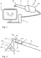
- a dental 3D-scanner 10 for scanning a 3-dimensional scan object is schematically illustrated.
- the dental 3D-scanner 10 includes a handheld housing 12.
- the handheld housing 12 has a widening rear section 12a to be held in the hand of an operator and a tapered front section 12b to be inserted into the mouth of a patient. Attached to the rear section 12a is a cable via which the handheld housing 12 is connected to a control device 14 that can, e.g., correspond to a personal computer.
- the dental 3D-scanner 10 has a window in its tapered front section 12b through which a light signal can pass and can reach a detector 16 inside the handheld housing 12.
- the dental 3D-scanner 10 is controlled by a control unit 18 that, in the illustrated example, is included in the control device 14.
- the dental 3D-scanner 10 of the present invention can particularly be put to use in a dentist's surgery or also in a dental laboratory to obtain an in-situ scan of a situation in the mouth of a patient.
- the situation in the mouth of a patient is scanned intraorally. It is, however, also possible that a scan object outside the mouth of a patient is scanned.
- the handheld housing 12 is hand-guided by a dentist or dental technician that moves the 3D-scanner around the scan object. This allows to obtain an in-situ scan to obtain a 3D representation. It is advantageous if a live visualization of the scan object, in particular the teeth or the jaw of the patient, is displayed on a screen during the data collection as schematically illustrated.
- the illustrated embodiment is an example and that it is also possible that the different components are arranged in a different way.
- the handheld housing 12 includes the control unit 18 and/or that the handheld housing 12 is connected via a wireless connection with the control device 14.
- the handheld housing 12 includes all components of the dental 3D-scanner and that only an image of the scan object is transferred to a separate external screen.
- the dental 3D-scanner 10 has a lens 20 through which a light signal from a scan object 22 passes prior to reaching the detector 16.
- the scan process thereby is based on a variable focal point 24.
- the focal point 24 corresponds to a focal plane.
- the focal point 24 is varied so that the entire spatial dimension of the scan object 22 is sampled.
- the image obtained by means of the detector 16 is focused at variable distances from the 3D-scanner 10 or its detector 16, respectively.
- the measurement principle thereby corresponds to a confocal microscope.
- the lens oscillates to periodically vary the focal point.
- the lens 20 is moved between a front oscillation position 20a and a rear oscillation position 20b.
- the focal point 24 is moved from a first position 24a above the scan object 22 to a second position 24b below the scan object 22 or the area of interest of the scan object 22.
- the lens 20 oscillates between the two positions at a constant oscillation frequency so that a constant sampling of the scan object 22 is obtained. Since the dental 3D-scanner 10 is not fixed in its position versus the scan object 22 but manually moved around the scan object 22 to allow for manual intraoral application, the oscillation frequency is thereby in the order of 10 Hz.
- a mirror 26 is arranged between the lens 20 and the scan object 22.
- the movement of the lens 20 is thereby obtained by means of an apparatus 28 for varying a focal point of an optical system according to the present invention.
- the apparatus 28 for varying a focal point of an optical system in the dental 3D-scanner of the present invention is schematically illustrated in a perspective view.
- the apparatus 28 includes a lens unit 30 with a lens 20 and a corresponding holding arrangement 32 for holding the lens 20, a guide unit 34 for guiding the movement of the lens unit 30 and a drive unit 36 for driving the movement.
- the lens unit 30 thereby includes all movable parts.
- the lens unit 30 is movable between a front reversal position as illustrated in Fig. 4 and a rear reversal position as illustrated in Fig. 3 .
- the distance to a detector (not illustrated in the Figs.) is increased so that the focal point of the optical system formed by the lens 20 and the detector is moved further away from the lens.
- the drive unit 36 includes a linear motor 38 with an anchor 40 and a stator 42.
- the anchor 40 is moved versus the stator 42 along a drive axis 44.
- a 3-phase linear servomotor is used as the linear motor 38.
- the linear motor 38 may include a hall sensor 39 (not illustrated) that is integrated with the linear motor housing and that provides a sensor signal to be used for controlling the power supply of the linear motor 38.
- the movement induced by the drive unit 36 is parallel to the drive axis 44.
- the drive axis 44 is parallel to an optical axis 46 of the lens 20 and a guide axis 48 along which the movement of the lens unit 30 is guided by the guide unit 34.
- the optical axis 46 of the lens 20 runs through the center of the lens 20.
- the linear movement of the lens unit 30 between the front reversal position and the rear reversal position is in the opposite direction of the movement of the anchor 40.
- the anchor 40 is moved backward as illustrated in Fig. 4 .
- a mass of the lens unit 30 is thereby equivalent to a mass of the anchor 40 so that optimal vibration cancellation is obtained. It is possible to add weight to one of the anchor 40 and the lens unit 30.
- the lens unit 30 is moved between the front reversal position and the rear reversal position.
- the distance between the front and rear reversal positions represents a maximum displacement.
- the linear motor 38 is controlled so that the movement of the lens unit 30 is subject to a smaller displacement.
- the use of a linear motor 38 has the advantage that the movement of the lens unit 30 can be inverted at any desired position between the front and rear reversal positions.
- a front and rear oscillation position correspond to positions in which the movement of the lens unit 30 is inverted.
- the distance between the front and rear oscillation positions is smaller than the distance between the front and rear reversal positions.
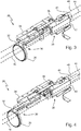
- the apparatus 28 is illustrated in a schematic side view to further describe the motion of the lens unit 30 and drive unit 36.
- a coupling arrangement 50 of the drive unit 36 is arranged between the linear motor 38 and the lens unit 30.
- the coupling arrangement 50 includes a flexible connection element 52 which transfers the force from the anchor 40 to the lens unit 30.
- the flexible connection element 52 is a steel strip which is sufficiently strong to transport the recurrent forces at higher oscillation frequencies and which allows transferring both tractive and compressive forces.
- the coupling arrangement 50 preferably includes a tension element 54 which comprises a spring in the illustrated embodiment.
- the tension element 54 is used to exert a force on the flexible connection element 52 so that this flexible connection element 52 is under tension and can transfer forces without shaking. This is particularly important when the movement of the lens unit 30 is inverted in the front or rear reversal positions or in the front or rear oscillation positions.
- the coupling arrangement 50 further includes an inverting element 56 which comprises a ball bearing in the illustrated embodiment. This inverting element 56 inverts the movement of the anchor 40 by guiding the flexible connection element 52 through a 180° direction change. In the illustrated embodiment, two ball bearings are used.
- the functionality of the guide unit 34 is illustrated based on a top view of the apparatus 28.
- the guide unit 34 connects the lens unit 30 and the drive unit 36.
- the guide unit 34 is affixed to the stator 42 of the linear motor 38.
- the lens unit 30 and the anchor 40 of the linear motor 38 are moved with respect to the guide unit 34 and the stator 42.
- the guide unit 34 includes a recirculating ball bearing guide 58 in which an engaging element 60 of the lens unit 30 is guided.
- the linear recirculating ball bearing guide 58 thereby functions comparable to a railing. By making use of a ball bearing, friction is minimized so that high oscillation frequencies are possible.
- the guide unit 34 includes a position sensor 62 which allows obtaining information on a position, in particular a lateral position, of the lens unit 30 with respect to the guide unit 34.
- the Dentsply Sirona Inc position sensor 62 is an optical sensor that measures a distance. This position of the lens unit 30 is direct measure of the current position of the lens and the focal point as well as the current position of the anchor 40 of the linear motor 38.
- the sensor signal of the position sensor 62 can be used to control the drive unit 36 so that a direct feedback and control loop becomes possible.
- the corresponding control can be exercised in a control unit that can also be included in a dental 3D-scanner or that can be externally arranged in a separate processing device.
- a centerline of mass 64 of the anchor 40 is equal to a centerline of mass 66 of the lens unit 30.
- the centerlines of mass 64, 66 are thereby parallel to the guide axis.
- the centerline of mass 64 of the anchor and the centerline of mass 66 of the lens unit are equal both in the side view and in the bottom view. This construction allows preventing torque forces from occurring.
Landscapes
- Health & Medical Sciences (AREA)
- Life Sciences & Earth Sciences (AREA)
- Physics & Mathematics (AREA)
- Animal Behavior & Ethology (AREA)
- Veterinary Medicine (AREA)
- Public Health (AREA)
- General Health & Medical Sciences (AREA)
- Optics & Photonics (AREA)
- Oral & Maxillofacial Surgery (AREA)
- Dentistry (AREA)
- Engineering & Computer Science (AREA)
- Biomedical Technology (AREA)
- Heart & Thoracic Surgery (AREA)
- Medical Informatics (AREA)
- Molecular Biology (AREA)
- Surgery (AREA)
- Biophysics (AREA)
- Pathology (AREA)
- General Physics & Mathematics (AREA)
- Audiology, Speech & Language Pathology (AREA)
- Nuclear Medicine, Radiotherapy & Molecular Imaging (AREA)
- Radiology & Medical Imaging (AREA)
- Epidemiology (AREA)
- Dental Tools And Instruments Or Auxiliary Dental Instruments (AREA)
- Endoscopes (AREA)
Claims (12)
- Vorrichtung (28) zur Veränderung eines Brennpunktes (24) eines optischen Systems in einem dentalen 3D-Scanner (10), umfassend:eine Linseneinheit (30) mit einer Linse (20), die zwischen einer vorderen Umkehrposition und einer hinteren Umkehrposition bewegbar ist, um eine Position eines Brennpunktes in Bezug auf ein Scan-Objekt (22) zu verändern;eine Führungseinheit (34) zum Führen einer Bewegung der Linseneinheit zwischen der vorderen Umkehrposition und der hinteren Umkehrposition entlang einer Führungsachse (48), die parallel zu einer optischen Achse (46) der Linse ist; undeine Antriebseinheit (36) zum Antreiben der Bewegung der Linseneinheit, wobei die genannte Antriebseinheit einen Linearmotor (38) mit einem Anker (40) und einem Stator (42) einschließt, wobei der genannte Anker entlang einer Antriebsachse (44) der Antriebseinheit bewegbar ist, die parallel zur Führungsachse ist, dadurch gekennzeichnet, dass der Stator an der Führungseinheit befestigt ist,wobei die Antriebseinheit (36) eine Kopplungsanordnung (50) zum Koppeln einer Bewegung des Ankers (40) und der Linseneinheit (30) einschließt, sodass eine Bewegung des Ankers in einer ersten Richtung auf eine Bewegung der Linse (20) in einer der ersten Richtung entgegengesetzten zweiten Richtung übertragen wird,wobei die Kopplungsanordnung (50) ein flexibles Verbindungselement (52) zum Verbinden des Ankers (40) und der Linseneinheit (30) einschließt, um eine Kraft vom Anker auf die Linseneinheit zu übertragen; undwobei die Kopplungsanordnung (50) ein invertierendes Element (56) zum Invertieren der Bewegung des Ankers (40) einschließt.
- Vorrichtung (28) nach Anspruch 1, wobei
die Kopplungsanordnung (50) ein Spannelement (54) zum Spannen des flexiblen Verbindungselements (52) einschließt. - Vorrichtung (28) nach einem der vorhergehenden Ansprüche, wobei
die Führungseinheit (34) einen Positionssensor (62) zum Bestimmen einer Position der Linseneinheit (30) zwischen der vorderen Umkehrposition und der hinteren Umkehrposition einschließt. - Vorrichtung (28) nach Anspruch 3, wobei die Antriebseinheit (36) konfiguriert ist, um die Bewegung der Linseneinheit (30) basierend auf einem Sensorsignal des Positionssensors (62) zu steuern.
- Vorrichtung (28) nach einem der vorhergehenden Ansprüche, wobei
die Führungseinheit (34) eine lineare Umlaufkugellagerführung (58) einschließt; und
die Linseneinheit (30) ein Eingriffselement (60) zum Eingreifen in die genannte lineare Umlaufkugellagerführung einschließt. - Vorrichtung (28) nach einem der vorhergehenden Ansprüche, wobei eine Masse der Linseneinheit (30) gleich einer Masse des Ankers (40) ist, um Reaktionskräfte zu kompensieren, die aus Beschleunigungen der Linse (20) und des Ankers resultieren.
- Vorrichtung (28) nach einem der vorhergehenden Ansprüche, wobei eine Massenmittellinie (66) der Linseneinheit (30) parallel zur Führungsachse (48) einer Massenmittellinie (64) des Ankers (40) parallel zur Führungsachse entspricht.
- Vorrichtung (28) nach einem der vorhergehenden Ansprüche, wobei der Linearmotor (38) ein bürstenloser 3-Phasen-Linear-Servomotor ist; und
der Linearmotor einen Hallsensor zum Messen einer Position des Ankers (40) in Bezug auf den Stator einschließt. - Vorrichtung (28) nach einem der vorhergehenden Ansprüche, wobei eine maximale Verlagerung des Ankers (40) gleich einem Abstand zwischen der vorderen Umkehrposition und der hinteren Umkehrposition ist.
- Vorrichtung (28) nach einem der vorhergehenden Ansprüche, wobei die Antriebseinheit (36) konfiguriert ist, um die Bewegung der Linseneinheit (30) anzutreiben, um zwischen einer wählbaren vorderen Schwingungsposition (20a) und einer wählbaren hinteren Schwingungsposition (20b) mit einer Schwingungsfrequenz von 2 bis 20 Hz zu schwingen.
- Dentaler 3D-Scanner (10) zum Scannen eines dreidimensionalen Scan-Objekts (22), umfassend:eine Vorrichtung (28), nach einem der vorhergehenden Ansprüche;einen Detektor (16) zum Detektieren eines durch die Linse (20) hindurchtretenden Lichtsignals von dem Scan-Objekt; undein in der Hand haltbares Gehäuse (12) zum manuellen Führen des 3D-Scanners um das Scan-Objekt.
- Dentaler 3D-Scanner (10) nach Anspruch 11, umfassend eine Steuereinheit (18) zum Steuern der Antriebseinheit (36).
Priority Applications (10)
| Application Number | Priority Date | Filing Date | Title |
|---|---|---|---|
| DK18197051.8T DK3628271T3 (da) | 2018-09-27 | 2018-09-27 | Apparat til ændring af et fokuspunkt for et optisk system i en dental 3d-scanner og dental 3d-scanner |
| EP18197051.8A EP3628271B1 (de) | 2018-09-27 | 2018-09-27 | Vorrichtung zur veränderung des brennpunktes eines optischen systems in einem dentalen 3d-scanner sowie ein dentaler 3d-scanner |
| BR112021004041-2A BR112021004041B1 (pt) | 2018-09-27 | 2019-09-27 | Aparelho para variar um ponto focal de um sistema óptico em um escâner 3d dental e escâner 3d dental |
| PCT/EP2019/076151 WO2020064992A1 (en) | 2018-09-27 | 2019-09-27 | Apparatus for varying a focal point of an optical system in a dental 3d-scanner and dental 3d-scanner |
| CA3109249A CA3109249C (en) | 2018-09-27 | 2019-09-27 | Apparatus for varying a focal point of an optical system in a dental 3d-scanner and dental 3d-scanner |
| KR1020217010623A KR102779552B1 (ko) | 2018-09-27 | 2019-09-27 | 치과용 3d 스캐너에서 광학 시스템의 초점을 변경하기 위한 장치 및 치과용 3d 스캐너 |
| AU2019348524A AU2019348524B2 (en) | 2018-09-27 | 2019-09-27 | Apparatus for varying a focal point of an optical system in a dental 3D-scanner and dental 3D-scanner |
| CN201980060689.8A CN112739289B (zh) | 2018-09-27 | 2019-09-27 | 用于改变牙科3d扫描仪中光学系统焦点的设备和牙科3d扫描仪 |
| US17/279,148 US12066686B2 (en) | 2018-09-27 | 2019-09-27 | Apparatus for varying a focal point of an optical system in a dental 3D-scanner and dental 3D-scanner |
| JP2021517227A JP7439068B2 (ja) | 2018-09-27 | 2019-09-27 | 歯科用3dスキャナ中の光学系の焦点を変化させるための装置及び歯科用3dスキャナ |
Applications Claiming Priority (1)
| Application Number | Priority Date | Filing Date | Title |
|---|---|---|---|
| EP18197051.8A EP3628271B1 (de) | 2018-09-27 | 2018-09-27 | Vorrichtung zur veränderung des brennpunktes eines optischen systems in einem dentalen 3d-scanner sowie ein dentaler 3d-scanner |
Publications (2)
| Publication Number | Publication Date |
|---|---|
| EP3628271A1 EP3628271A1 (de) | 2020-04-01 |
| EP3628271B1 true EP3628271B1 (de) | 2021-07-21 |
Family
ID=63685803
Family Applications (1)
| Application Number | Title | Priority Date | Filing Date |
|---|---|---|---|
| EP18197051.8A Active EP3628271B1 (de) | 2018-09-27 | 2018-09-27 | Vorrichtung zur veränderung des brennpunktes eines optischen systems in einem dentalen 3d-scanner sowie ein dentaler 3d-scanner |
Country Status (9)
| Country | Link |
|---|---|
| US (1) | US12066686B2 (de) |
| EP (1) | EP3628271B1 (de) |
| JP (1) | JP7439068B2 (de) |
| KR (1) | KR102779552B1 (de) |
| CN (1) | CN112739289B (de) |
| AU (1) | AU2019348524B2 (de) |
| CA (1) | CA3109249C (de) |
| DK (1) | DK3628271T3 (de) |
| WO (1) | WO2020064992A1 (de) |
Cited By (1)
| Publication number | Priority date | Publication date | Assignee | Title |
|---|---|---|---|---|
| EP4467925A1 (de) * | 2023-05-24 | 2024-11-27 | J. Morita Manufacturing Corporation | Dreidimensionaler scanner und steuerungsverfahren |
Families Citing this family (2)
| Publication number | Priority date | Publication date | Assignee | Title |
|---|---|---|---|---|
| EP4502535A3 (de) * | 2021-12-22 | 2025-03-12 | 3Shape A/S | Scanner mit neuartigem linsenantriebsmechanismus |
| JP2025167538A (ja) * | 2024-04-26 | 2025-11-07 | 株式会社モリタ製作所 | 医療用診療装置 |
Family Cites Families (16)
| Publication number | Priority date | Publication date | Assignee | Title |
|---|---|---|---|---|
| US4902083A (en) * | 1988-05-31 | 1990-02-20 | Reflection Technology, Inc. | Low vibration resonant scanning unit for miniature optical display apparatus |
| US5210636A (en) * | 1991-07-19 | 1993-05-11 | Baer Stephen C | Rotational oscillatory optical scanning device |
| DE10356412A1 (de) * | 2003-11-24 | 2005-06-23 | Universität Stuttgart | Multifokales konfokales Verfahren und konfokale Anordnung für wenig kooperative Objekte |
| DE112004003014T5 (de) * | 2004-11-15 | 2008-01-03 | Kabushiki Kaisha Morita Tokyo Seisakusho | Optische Zahndiagnosevorrichtung |
| DE102007005726B4 (de) | 2007-01-31 | 2010-05-12 | Sirona Dental Systems Gmbh | Vorrichtung und Verfahren zur optischen 3D-Vermessung |
| DE102007005625A1 (de) | 2007-01-31 | 2008-08-07 | Gaus, Harry, Dr. | Dentalkamera zur 3D-Vermessung mit Scaneinrichtung |
| US7933056B2 (en) | 2007-09-26 | 2011-04-26 | Che-Chih Tsao | Methods and systems of rapid focusing and zooming for volumetric 3D displays and cameras |
| ATE487111T1 (de) | 2007-10-18 | 2010-11-15 | Nectar Imaging S R L | Vorrichtung zur tomografischen erfassung von objekten |
| CN201369764Y (zh) * | 2009-02-17 | 2009-12-23 | 杭州华杭科技有限公司 | 扫描仪 |
| CA2763826C (en) | 2009-06-17 | 2020-04-07 | 3Shape A/S | Focus scanning apparatus |
| US8134719B2 (en) * | 2010-03-19 | 2012-03-13 | Carestream Health, Inc. | 3-D imaging using telecentric defocus |
| US10218955B2 (en) * | 2010-12-21 | 2019-02-26 | 3Shape A/S | Motion blur compensation |
| JP5945814B2 (ja) | 2011-12-05 | 2016-07-05 | パナソニックIpマネジメント株式会社 | リニアアクチュエータおよびこれを備える口腔衛生装置 |
| DE102015209404B4 (de) * | 2015-05-22 | 2018-05-03 | Sirona Dental Systems Gmbh | Verfahren und Kamera zur dreidimensionalen Vermessung eines dentalen Objekts |
| CN110168908B (zh) * | 2016-12-27 | 2021-05-11 | 株式会社开道 | 三相/单相交流电源对应型电动卷扬机 |
| US10456043B2 (en) * | 2017-01-12 | 2019-10-29 | Align Technology, Inc. | Compact confocal dental scanning apparatus |
-
2018
- 2018-09-27 EP EP18197051.8A patent/EP3628271B1/de active Active
- 2018-09-27 DK DK18197051.8T patent/DK3628271T3/da active
-
2019
- 2019-09-27 JP JP2021517227A patent/JP7439068B2/ja active Active
- 2019-09-27 WO PCT/EP2019/076151 patent/WO2020064992A1/en not_active Ceased
- 2019-09-27 CA CA3109249A patent/CA3109249C/en active Active
- 2019-09-27 US US17/279,148 patent/US12066686B2/en active Active
- 2019-09-27 AU AU2019348524A patent/AU2019348524B2/en active Active
- 2019-09-27 CN CN201980060689.8A patent/CN112739289B/zh active Active
- 2019-09-27 KR KR1020217010623A patent/KR102779552B1/ko active Active
Cited By (1)
| Publication number | Priority date | Publication date | Assignee | Title |
|---|---|---|---|---|
| EP4467925A1 (de) * | 2023-05-24 | 2024-11-27 | J. Morita Manufacturing Corporation | Dreidimensionaler scanner und steuerungsverfahren |
Also Published As
| Publication number | Publication date |
|---|---|
| JP7439068B2 (ja) | 2024-02-27 |
| AU2019348524A1 (en) | 2021-03-04 |
| WO2020064992A1 (en) | 2020-04-02 |
| CN112739289B (zh) | 2022-06-24 |
| US12066686B2 (en) | 2024-08-20 |
| EP3628271A1 (de) | 2020-04-01 |
| DK3628271T3 (da) | 2021-09-06 |
| CN112739289A (zh) | 2021-04-30 |
| KR102779552B1 (ko) | 2025-03-10 |
| US20210389549A1 (en) | 2021-12-16 |
| CA3109249A1 (en) | 2020-04-02 |
| JP2022502176A (ja) | 2022-01-11 |
| BR112021004041A2 (pt) | 2021-05-25 |
| CA3109249C (en) | 2023-05-23 |
| KR20210068454A (ko) | 2021-06-09 |
| AU2019348524B2 (en) | 2024-06-27 |
Similar Documents
| Publication | Publication Date | Title |
|---|---|---|
| JP5189287B2 (ja) | 歯科用レーザデジタイザシステム | |
| US12066686B2 (en) | Apparatus for varying a focal point of an optical system in a dental 3D-scanner and dental 3D-scanner | |
| US5569578A (en) | Method and apparatus for effecting change in shape of pre-existing object | |
| EP2901917A1 (de) | Scanner für die mundhöhle | |
| KR101371211B1 (ko) | 구강용 스캐너 | |
| CN107949309B (zh) | 光相干断层图像生成装置 | |
| JP2015083978A (ja) | 焦点操作装置 | |
| KR101401927B1 (ko) | 치과용 파노라마 및 씨티 겸용 x선 촬영장치 | |
| CN110996841A (zh) | 使用光片主动三角测量的自动口内3d扫描仪 | |
| JP2019524327A (ja) | 低コヒーレンス範囲を有する自動口腔内3dスキャナ | |
| KR20160137414A (ko) | 마우스피스형 구강 스캐너 | |
| KR20210055436A (ko) | 아치 형태를 이용한 개인맞춤 치과용 파노라마 시스템 및 이의 제어 방법 | |
| KR101337239B1 (ko) | 치과용 파노라마 및 씨티 겸용 x선 촬영장치의 회전암 구동 구조체 | |
| BR112021004041B1 (pt) | Aparelho para variar um ponto focal de um sistema óptico em um escâner 3d dental e escâner 3d dental | |
| JP7783851B2 (ja) | 三次元スキャナおよび制御方法 | |
| JP2025167538A (ja) | 医療用診療装置 | |
| JP7762179B2 (ja) | 三次元スキャナおよび制御方法 | |
| JP6774365B2 (ja) | 撮像装置および撮像装置の筺体から着脱可能である先端部材 | |
| JP2007181577A (ja) | 歯牙固定カメラ | |
| CN116327116A (zh) | 包括新型透镜驱动机构的扫描仪 |
Legal Events
| Date | Code | Title | Description |
|---|---|---|---|
| PUAI | Public reference made under article 153(3) epc to a published international application that has entered the european phase |
Free format text: ORIGINAL CODE: 0009012 |
|
| STAA | Information on the status of an ep patent application or granted ep patent |
Free format text: STATUS: THE APPLICATION HAS BEEN PUBLISHED |
|
| AK | Designated contracting states |
Kind code of ref document: A1 Designated state(s): AL AT BE BG CH CY CZ DE DK EE ES FI FR GB GR HR HU IE IS IT LI LT LU LV MC MK MT NL NO PL PT RO RS SE SI SK SM TR |
|
| AX | Request for extension of the european patent |
Extension state: BA ME |
|
| STAA | Information on the status of an ep patent application or granted ep patent |
Free format text: STATUS: REQUEST FOR EXAMINATION WAS MADE |
|
| 17P | Request for examination filed |
Effective date: 20200727 |
|
| RBV | Designated contracting states (corrected) |
Designated state(s): AL AT BE BG CH CY CZ DE DK EE ES FI FR GB GR HR HU IE IS IT LI LT LU LV MC MK MT NL NO PL PT RO RS SE SI SK SM TR |
|
| GRAP | Despatch of communication of intention to grant a patent |
Free format text: ORIGINAL CODE: EPIDOSNIGR1 |
|
| STAA | Information on the status of an ep patent application or granted ep patent |
Free format text: STATUS: GRANT OF PATENT IS INTENDED |
|
| RIC1 | Information provided on ipc code assigned before grant |
Ipc: G02B 27/64 20060101ALN20210225BHEP Ipc: A61B 5/00 20060101ALI20210225BHEP Ipc: G02B 7/08 20210101ALI20210225BHEP Ipc: A61C 9/00 20060101AFI20210225BHEP |
|
| INTG | Intention to grant announced |
Effective date: 20210318 |
|
| GRAS | Grant fee paid |
Free format text: ORIGINAL CODE: EPIDOSNIGR3 |
|
| GRAA | (expected) grant |
Free format text: ORIGINAL CODE: 0009210 |
|
| STAA | Information on the status of an ep patent application or granted ep patent |
Free format text: STATUS: THE PATENT HAS BEEN GRANTED |
|
| AK | Designated contracting states |
Kind code of ref document: B1 Designated state(s): AL AT BE BG CH CY CZ DE DK EE ES FI FR GB GR HR HU IE IS IT LI LT LU LV MC MK MT NL NO PL PT RO RS SE SI SK SM TR |
|
| REG | Reference to a national code |
Ref country code: GB Ref legal event code: FG4D |
|
| REG | Reference to a national code |
Ref country code: CH Ref legal event code: EP |
|
| REG | Reference to a national code |
Ref country code: DE Ref legal event code: R096 Ref document number: 602018020336 Country of ref document: DE |
|
| REG | Reference to a national code |
Ref country code: AT Ref legal event code: REF Ref document number: 1411891 Country of ref document: AT Kind code of ref document: T Effective date: 20210815 |
|
| REG | Reference to a national code |
Ref country code: IE Ref legal event code: FG4D |
|
| REG | Reference to a national code |
Ref country code: DK Ref legal event code: T3 Effective date: 20210901 |
|
| REG | Reference to a national code |
Ref country code: LT Ref legal event code: MG9D |
|
| REG | Reference to a national code |
Ref country code: NL Ref legal event code: MP Effective date: 20210721 |
|
| PG25 | Lapsed in a contracting state [announced via postgrant information from national office to epo] |
Ref country code: LT Free format text: LAPSE BECAUSE OF FAILURE TO SUBMIT A TRANSLATION OF THE DESCRIPTION OR TO PAY THE FEE WITHIN THE PRESCRIBED TIME-LIMIT Effective date: 20210721 Ref country code: BG Free format text: LAPSE BECAUSE OF FAILURE TO SUBMIT A TRANSLATION OF THE DESCRIPTION OR TO PAY THE FEE WITHIN THE PRESCRIBED TIME-LIMIT Effective date: 20211021 Ref country code: PT Free format text: LAPSE BECAUSE OF FAILURE TO SUBMIT A TRANSLATION OF THE DESCRIPTION OR TO PAY THE FEE WITHIN THE PRESCRIBED TIME-LIMIT Effective date: 20211122 Ref country code: NO Free format text: LAPSE BECAUSE OF FAILURE TO SUBMIT A TRANSLATION OF THE DESCRIPTION OR TO PAY THE FEE WITHIN THE PRESCRIBED TIME-LIMIT Effective date: 20211021 Ref country code: NL Free format text: LAPSE BECAUSE OF FAILURE TO SUBMIT A TRANSLATION OF THE DESCRIPTION OR TO PAY THE FEE WITHIN THE PRESCRIBED TIME-LIMIT Effective date: 20210721 Ref country code: RS Free format text: LAPSE BECAUSE OF FAILURE TO SUBMIT A TRANSLATION OF THE DESCRIPTION OR TO PAY THE FEE WITHIN THE PRESCRIBED TIME-LIMIT Effective date: 20210721 Ref country code: SE Free format text: LAPSE BECAUSE OF FAILURE TO SUBMIT A TRANSLATION OF THE DESCRIPTION OR TO PAY THE FEE WITHIN THE PRESCRIBED TIME-LIMIT Effective date: 20210721 Ref country code: HR Free format text: LAPSE BECAUSE OF FAILURE TO SUBMIT A TRANSLATION OF THE DESCRIPTION OR TO PAY THE FEE WITHIN THE PRESCRIBED TIME-LIMIT Effective date: 20210721 Ref country code: ES Free format text: LAPSE BECAUSE OF FAILURE TO SUBMIT A TRANSLATION OF THE DESCRIPTION OR TO PAY THE FEE WITHIN THE PRESCRIBED TIME-LIMIT Effective date: 20210721 Ref country code: FI Free format text: LAPSE BECAUSE OF FAILURE TO SUBMIT A TRANSLATION OF THE DESCRIPTION OR TO PAY THE FEE WITHIN THE PRESCRIBED TIME-LIMIT Effective date: 20210721 |
|
| PG25 | Lapsed in a contracting state [announced via postgrant information from national office to epo] |
Ref country code: PL Free format text: LAPSE BECAUSE OF FAILURE TO SUBMIT A TRANSLATION OF THE DESCRIPTION OR TO PAY THE FEE WITHIN THE PRESCRIBED TIME-LIMIT Effective date: 20210721 Ref country code: LV Free format text: LAPSE BECAUSE OF FAILURE TO SUBMIT A TRANSLATION OF THE DESCRIPTION OR TO PAY THE FEE WITHIN THE PRESCRIBED TIME-LIMIT Effective date: 20210721 Ref country code: GR Free format text: LAPSE BECAUSE OF FAILURE TO SUBMIT A TRANSLATION OF THE DESCRIPTION OR TO PAY THE FEE WITHIN THE PRESCRIBED TIME-LIMIT Effective date: 20211022 |
|
| REG | Reference to a national code |
Ref country code: DE Ref legal event code: R097 Ref document number: 602018020336 Country of ref document: DE |
|
| REG | Reference to a national code |
Ref country code: BE Ref legal event code: MM Effective date: 20210930 |
|
| PLBE | No opposition filed within time limit |
Free format text: ORIGINAL CODE: 0009261 |
|
| STAA | Information on the status of an ep patent application or granted ep patent |
Free format text: STATUS: NO OPPOSITION FILED WITHIN TIME LIMIT |
|
| PG25 | Lapsed in a contracting state [announced via postgrant information from national office to epo] |
Ref country code: SM Free format text: LAPSE BECAUSE OF FAILURE TO SUBMIT A TRANSLATION OF THE DESCRIPTION OR TO PAY THE FEE WITHIN THE PRESCRIBED TIME-LIMIT Effective date: 20210721 Ref country code: SK Free format text: LAPSE BECAUSE OF FAILURE TO SUBMIT A TRANSLATION OF THE DESCRIPTION OR TO PAY THE FEE WITHIN THE PRESCRIBED TIME-LIMIT Effective date: 20210721 Ref country code: RO Free format text: LAPSE BECAUSE OF FAILURE TO SUBMIT A TRANSLATION OF THE DESCRIPTION OR TO PAY THE FEE WITHIN THE PRESCRIBED TIME-LIMIT Effective date: 20210721 Ref country code: MC Free format text: LAPSE BECAUSE OF FAILURE TO SUBMIT A TRANSLATION OF THE DESCRIPTION OR TO PAY THE FEE WITHIN THE PRESCRIBED TIME-LIMIT Effective date: 20210721 Ref country code: EE Free format text: LAPSE BECAUSE OF FAILURE TO SUBMIT A TRANSLATION OF THE DESCRIPTION OR TO PAY THE FEE WITHIN THE PRESCRIBED TIME-LIMIT Effective date: 20210721 Ref country code: CZ Free format text: LAPSE BECAUSE OF FAILURE TO SUBMIT A TRANSLATION OF THE DESCRIPTION OR TO PAY THE FEE WITHIN THE PRESCRIBED TIME-LIMIT Effective date: 20210721 Ref country code: AL Free format text: LAPSE BECAUSE OF FAILURE TO SUBMIT A TRANSLATION OF THE DESCRIPTION OR TO PAY THE FEE WITHIN THE PRESCRIBED TIME-LIMIT Effective date: 20210721 |
|
| 26N | No opposition filed |
Effective date: 20220422 |
|
| PG25 | Lapsed in a contracting state [announced via postgrant information from national office to epo] |
Ref country code: LU Free format text: LAPSE BECAUSE OF NON-PAYMENT OF DUE FEES Effective date: 20210927 Ref country code: IE Free format text: LAPSE BECAUSE OF NON-PAYMENT OF DUE FEES Effective date: 20210927 Ref country code: BE Free format text: LAPSE BECAUSE OF NON-PAYMENT OF DUE FEES Effective date: 20210930 |
|
| REG | Reference to a national code |
Ref country code: AT Ref legal event code: UEP Ref document number: 1411891 Country of ref document: AT Kind code of ref document: T Effective date: 20210721 |
|
| P01 | Opt-out of the competence of the unified patent court (upc) registered |
Effective date: 20230509 |
|
| PG25 | Lapsed in a contracting state [announced via postgrant information from national office to epo] |
Ref country code: CY Free format text: LAPSE BECAUSE OF FAILURE TO SUBMIT A TRANSLATION OF THE DESCRIPTION OR TO PAY THE FEE WITHIN THE PRESCRIBED TIME-LIMIT Effective date: 20210721 |
|
| PG25 | Lapsed in a contracting state [announced via postgrant information from national office to epo] |
Ref country code: HU Free format text: LAPSE BECAUSE OF FAILURE TO SUBMIT A TRANSLATION OF THE DESCRIPTION OR TO PAY THE FEE WITHIN THE PRESCRIBED TIME-LIMIT; INVALID AB INITIO Effective date: 20180927 |
|
| PG25 | Lapsed in a contracting state [announced via postgrant information from national office to epo] |
Ref country code: MK Free format text: LAPSE BECAUSE OF FAILURE TO SUBMIT A TRANSLATION OF THE DESCRIPTION OR TO PAY THE FEE WITHIN THE PRESCRIBED TIME-LIMIT Effective date: 20210721 |
|
| PG25 | Lapsed in a contracting state [announced via postgrant information from national office to epo] |
Ref country code: MT Free format text: LAPSE BECAUSE OF FAILURE TO SUBMIT A TRANSLATION OF THE DESCRIPTION OR TO PAY THE FEE WITHIN THE PRESCRIBED TIME-LIMIT Effective date: 20210721 |
|
| PGFP | Annual fee paid to national office [announced via postgrant information from national office to epo] |
Ref country code: DK Payment date: 20240913 Year of fee payment: 7 |
|
| PGFP | Annual fee paid to national office [announced via postgrant information from national office to epo] |
Ref country code: AT Payment date: 20240827 Year of fee payment: 7 |
|
| PGFP | Annual fee paid to national office [announced via postgrant information from national office to epo] |
Ref country code: CH Payment date: 20241001 Year of fee payment: 7 |
|
| PGFP | Annual fee paid to national office [announced via postgrant information from national office to epo] |
Ref country code: DE Payment date: 20250820 Year of fee payment: 8 |
|
| PGFP | Annual fee paid to national office [announced via postgrant information from national office to epo] |
Ref country code: IT Payment date: 20250820 Year of fee payment: 8 |
|
| PGFP | Annual fee paid to national office [announced via postgrant information from national office to epo] |
Ref country code: GB Payment date: 20250820 Year of fee payment: 8 |
|
| PGFP | Annual fee paid to national office [announced via postgrant information from national office to epo] |
Ref country code: FR Payment date: 20250820 Year of fee payment: 8 |
|
| PG25 | Lapsed in a contracting state [announced via postgrant information from national office to epo] |
Ref country code: TR Free format text: LAPSE BECAUSE OF FAILURE TO SUBMIT A TRANSLATION OF THE DESCRIPTION OR TO PAY THE FEE WITHIN THE PRESCRIBED TIME-LIMIT Effective date: 20210721 |