EP4201167A1 - Chassis with braking device - Google Patents
Chassis with braking device Download PDFInfo
- Publication number
- EP4201167A1 EP4201167A1 EP22213414.0A EP22213414A EP4201167A1 EP 4201167 A1 EP4201167 A1 EP 4201167A1 EP 22213414 A EP22213414 A EP 22213414A EP 4201167 A1 EP4201167 A1 EP 4201167A1
- Authority
- EP
- European Patent Office
- Prior art keywords
- brake
- stub
- axle
- chassis
- stubs
- Prior art date
- Legal status (The legal status is an assumption and is not a legal conclusion. Google has not performed a legal analysis and makes no representation as to the accuracy of the status listed.)
- Pending
Links
- 239000002689 soil Substances 0.000 description 8
- 230000000694 effects Effects 0.000 description 6
- 230000007480 spreading Effects 0.000 description 5
- 238000003971 tillage Methods 0.000 description 5
- 230000008901 benefit Effects 0.000 description 3
- 239000003337 fertilizer Substances 0.000 description 3
- 230000033001 locomotion Effects 0.000 description 3
- 239000000463 material Substances 0.000 description 3
- 238000009331 sowing Methods 0.000 description 3
- 230000005540 biological transmission Effects 0.000 description 2
- 238000004140 cleaning Methods 0.000 description 2
- 230000006835 compression Effects 0.000 description 2
- 238000007906 compression Methods 0.000 description 2
- 102000004315 Forkhead Transcription Factors Human genes 0.000 description 1
- 108090000852 Forkhead Transcription Factors Proteins 0.000 description 1
- 230000008878 coupling Effects 0.000 description 1
- 238000010168 coupling process Methods 0.000 description 1
- 238000005859 coupling reaction Methods 0.000 description 1
- 238000009434 installation Methods 0.000 description 1
- 230000007246 mechanism Effects 0.000 description 1
- 230000002028 premature Effects 0.000 description 1
- 238000003860 storage Methods 0.000 description 1
Images

Classifications
-
- A—HUMAN NECESSITIES
- A01—AGRICULTURE; FORESTRY; ANIMAL HUSBANDRY; HUNTING; TRAPPING; FISHING
- A01B—SOIL WORKING IN AGRICULTURE OR FORESTRY; PARTS, DETAILS, OR ACCESSORIES OF AGRICULTURAL MACHINES OR IMPLEMENTS, IN GENERAL
- A01B29/00—Rollers
- A01B29/04—Rollers with non-smooth surface formed of rotatably-mounted rings or discs or with projections or ribs on the roller body; Land packers
- A01B29/041—Rollers with non-smooth surface formed of rotatably-mounted rings or discs or with projections or ribs on the roller body; Land packers of "Cambridge"-type, i.e. the soil-pressing rings being stacked on a shaft
- A01B29/043—Tire-packers
-
- A—HUMAN NECESSITIES
- A01—AGRICULTURE; FORESTRY; ANIMAL HUSBANDRY; HUNTING; TRAPPING; FISHING
- A01B—SOIL WORKING IN AGRICULTURE OR FORESTRY; PARTS, DETAILS, OR ACCESSORIES OF AGRICULTURAL MACHINES OR IMPLEMENTS, IN GENERAL
- A01B49/00—Combined machines
- A01B49/04—Combinations of soil-working tools with non-soil-working tools, e.g. planting tools
- A01B49/06—Combinations of soil-working tools with non-soil-working tools, e.g. planting tools for sowing or fertilising
-
- B—PERFORMING OPERATIONS; TRANSPORTING
- B60—VEHICLES IN GENERAL
- B60B—VEHICLE WHEELS; CASTORS; AXLES FOR WHEELS OR CASTORS; INCREASING WHEEL ADHESION
- B60B27/00—Hubs
- B60B27/0047—Hubs characterised by functional integration of other elements
-
- B—PERFORMING OPERATIONS; TRANSPORTING
- B60—VEHICLES IN GENERAL
- B60B—VEHICLE WHEELS; CASTORS; AXLES FOR WHEELS OR CASTORS; INCREASING WHEEL ADHESION
- B60B35/00—Axle units; Parts thereof ; Arrangements for lubrication of axles
- B60B35/02—Dead axles, i.e. not transmitting torque
- B60B35/04—Dead axles, i.e. not transmitting torque straight
-
- B—PERFORMING OPERATIONS; TRANSPORTING
- B60—VEHICLES IN GENERAL
- B60T—VEHICLE BRAKE CONTROL SYSTEMS OR PARTS THEREOF; BRAKE CONTROL SYSTEMS OR PARTS THEREOF, IN GENERAL; ARRANGEMENT OF BRAKING ELEMENTS ON VEHICLES IN GENERAL; PORTABLE DEVICES FOR PREVENTING UNWANTED MOVEMENT OF VEHICLES; VEHICLE MODIFICATIONS TO FACILITATE COOLING OF BRAKES
- B60T11/00—Transmitting braking action from initiating means to ultimate brake actuator without power assistance or drive or where such assistance or drive is irrelevant
- B60T11/04—Transmitting braking action from initiating means to ultimate brake actuator without power assistance or drive or where such assistance or drive is irrelevant transmitting mechanically
-
- B—PERFORMING OPERATIONS; TRANSPORTING
- B60—VEHICLES IN GENERAL
- B60B—VEHICLE WHEELS; CASTORS; AXLES FOR WHEELS OR CASTORS; INCREASING WHEEL ADHESION
- B60B35/00—Axle units; Parts thereof ; Arrangements for lubrication of axles
- B60B35/12—Torque-transmitting axles
- B60B35/14—Torque-transmitting axles composite or split, e.g. half- axles; Couplings between axle parts or sections
Definitions
- the invention relates to a paired arrangement of brake axle stubs according to the preamble of patent claim 1.
- Agricultural machines for example for tillage and/or sowing, are off EP2055164B1 known.
- the device combination described there combines tools for tillage and a subsequent device for spreading fertilizer and/or seed.
- the implement combination has a chassis packer roller, which supports the majority of the weight of the machine as well as that of the fertilizer and/or seed carried in a storage container on the ground.
- a large number of wheels of the chassis are arranged side by side over the entire working width of the implement combination in order to press down and reconsolidate the soil loosened by the tillage tools.
- the object of the invention is to create an arrangement of brake axle stubs which avoids the above disadvantages.
- a chassis of a preferably agricultural vehicle or mobile device with an arrangement of brake axle stubs and wheels is moved or transported in a direction of travel over a ground surface.
- the brake axle stubs have a stub axle with a braking device on which a wheel hub is rotatably mounted and is operatively connected to the braking device, with at least one wheel being attached to each wheel hub.
- a brake actuation shaft for introducing an applied brake actuation torque into the braking device of the brake axle stub is arranged on the brake axle stub.
- the brake actuation torque can be applied directly by an actuator or indirectly via a lever or gear.
- the axle centers of the stub axles are at a distance from one another. The distance is measured horizontally in the direction of travel of the vehicle.
- the brake actuation shafts are arranged approximately coaxially with one another and are therefore aligned with one another. Due to the aligned alignment of the brake actuation shafts of the two brake axle stubs, the braking torques can be applied with a device that was previously only known from continuous brake axles.
- a braking force can be applied to the lever ends protruding from the brake actuation shafts.
- the braking force is transmitted via the brake lever as a braking torque by means of the brake actuation shafts to the brake axle stub and initiates the braking.
- the brake axle stubs are designed or equipped with drum brakes, with brake actuating shafts moving one or more cams eccentric cams, which in turn press one or more brake shoes against the inner surface of a brake drum and initiate the braking effect by friction.
- the brake shafts can also be arranged in such a way that a spreading or clamping effect is achieved on a brake disc instead of a drum brake.
- two brake levers are arranged side by side between the paired brake axle stubs on the respective brake actuating shafts.
- a balance beam is arranged between the lever ends of the brake levers. This is suitable for compensating misalignment of the lever ends, which can occur with deviating settings or brake wear.
- At least one actuating element which applies the braking force to the lever, is assigned to one or both brake levers.
- the actuating element can be designed directly as a pressure or tension cylinder, but also as a pressure rod or traction mechanism in order to indirectly apply pressure and/or traction to actuate the brake.
- the braking force can also be applied via an overrun braking device or a manual parking brake device.
- a combined traction/compression force transmission is also included, as can be found in a combination of a service brake system together with a further parking brake system.
- an actuating element are traction devices such as ropes, chains and tie rods, but also compression struts, actuating linkage with countershaft and Includes transmission gears to increase the applied braking forces or travel.
- At least one brake lever has an adjusting device for changing its angular position relative to the brake actuation shaft.
- a brake lever can be equipped with an adjustment device that can be actuated manually or as a function of wear. Due to the adjustability, differences in the braking effect can be easily corrected initially during commissioning as well as in the event of wear and tear of the brake system.
- An adjustment device is preferably designed as a worm gear or adjustable Hirth toothing, which is arranged between the end of the brake lever and the brake actuation shaft.
- the running gear preferably has a running gear frame with at least one cross member, from which a central web protrudes for each offset pair of wheels or extends into the brake axle area. This is arranged between each pair of brake axle stubs.
- the brake axle stubs can be welded to the center bar, clamped or fixed with other form-fitting elements.
- a central web preferably has a detachable connection to the chassis frame and/or the brake axle stubs, in order to simplify assembly/disassembly of the brake axle stubs or the wheels, particularly when space is limited.
- An assembly-friendly arrangement of the stub axles of the stub brake axles on the central web is achieved in that the stub axles have a flange at their end opposite the wheel hub, which flange fixes the stub brake axles to the central web.
- One or more fasteners are used for fixing. These can also be supported by other form-fitting elements in the fixing effect.
- the respective brake axle stubs have at least one, preferably several fastening means with their flange, with at least one fastening means being connected together with the flange of the first brake axle stub and the flange of the second brake axle stub arranged on the other side of the central web, a space-saving, space-optimized flange connection is achieved reached.
- Both the central web and the flanges of the brake axle stub have recesses or bores through which a clamping connection, for example screws and nuts, threaded bores or threaded bolts, acts.
- flanges that are offset relative to one another in the direction of travel can overlap laterally, it is advantageous if at least one, preferably two, fastening means act jointly on both flanges where they overlap or where their recesses are aligned with one another.
- a respective flange has four recesses and the central web standing between them has six recesses for receiving fastening means.
- the respective outer recesses of the central web have the same distances from one another to the recesses lying in between as the corresponding recesses of the flanges, measured at least in the direction of travel.
- the invention is characterized in particular by the fact that a combination of an offset of the wheel axles and an aligned arrangement of the brake shafts results in a simple, cost-effective brake system which, on the other hand, has a low susceptibility to dirt and thus increased operational reliability.
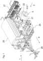
- FIG. 1 shows a vehicle 1 designed as an agricultural sowing combination.
- the vehicle 1 has a drawbar 29 in the front area, which is for coupling and moving the vehicle 1 to a towing vehicle, not shown. The locomotion takes place in the direction of travel 6.
- the towing vehicle has a hydraulic or pneumatic pressure supply, which is connected to the braking system of the vehicle 1.
- the vehicle 1 has a chassis 2 for operation and transport in the central to rear area, which carries a larger part of the weight of the vehicle 1 and supports it on the ground.
- In the front area of the chassis 2 there is a section with several soil cultivation tools 25 distributed over the working width of the vehicle, preferably such that they can be lifted out.
- the wheels 5 of the chassis 2 which are offset from one another in the direction of travel 6 over the entire width of the vehicle 1 , can reconsolidate the soil previously loosened by the tools 25 .
- a further spreading device 27 is arranged behind the chassis 2, with which material such as seed or fertilizer can be spread onto the ground traveled over or worked into it. The material is preferably carried along in a container 26 and is applied to an agricultural area by the application devices 27 .
- a reconsolidation of the loosened soil over almost the entire surface by the wheels 5 is advantageous in order to create better emergence conditions for the seed subsequently introduced into the ground by the spreading device 27 .
- the chassis components are arranged by means of a chassis frame 21, which extends transversely to the direction of travel 6, in particular in the rear region of the chassis 2.
- the chassis consists of six wheels 5 arranged next to one another, three of which are visible and three more are covered by the container 26 . Every second wheel is offset from an adjacent wheel in the direction of travel 6, in which the stub axles 7 of the associated brake axle stubs 3 and 4 are spaced apart from one another. In each case, two brake axle stubs 3 and 4 protrude left and right from a central web 22 which extends forward and is connected to the chassis frame 21 .
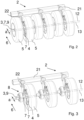
- FIG 2 shows the relevant part of the chassis 2 with the cross member of the chassis frame 21 arranged transversely to the direction of travel 6, from which three central webs 22 extend backwards and downwards into the axle area.
- a respective central web 22 To the right and left of a respective central web 22 is a first, front brake axle stub 3 and a further, rear brake axle stub 4, offset from one another by the distance a in the direction of travel 6.
- the stub axles 7 of the respective front brake stub axles 3 lie on a common axle center 12, the other stub axles 7 of the rear brake stub axles 4 on the axle center 13 consisting of tire and rim is flanged.
- FIG. 1 Analogous to figure 2 shows figure 3 the same arrangement of the chassis 2, which, however, is shown for the sake of clarity only with the second, fourth and sixth wheel 5 each offset to the rear.
- the braking devices 8 are visible through the other three front wheels that have been left out.
- the front brake stub axles 3 are offset, measured in the direction of travel 6, by the distance a from the rear brake stub axles 4, in that the associated stub axles 7 are aligned on the same front axle center 12 and rear axle center 13, which consequently also have the distance a from one another measured in the direction of travel 6 .
- a brake drum is also fixedly connected to the wheel hub 9 and is rotatably connected relative to the stub axle 7 .
- the actual braking device 8 is in the following figure 4 shown in detail:
- To the right and left of the central web 22 is a front stub brake axle 3 and a rear stub brake axle 4 in the direction of travel 6 offset from one another.
- the axle centers 12 and 13 of the respective stub axles 7 have the distance a from one another, measured in the direction of travel.
- the distance a preferably corresponds to at least one cross-section of a stub axle 7, which also extends in the direction of travel 6 is measured.
- a brake actuation shaft 11 protrudes from the axle center 12 of the brake axle stub 3 and a brake actuation shaft 12 protrudes eccentrically from the axle center 13 of the brake axle stub 4 .
- the respective brake axle stubs 3 and 4 are twisted relative to one another about the respective axle centers 12 and 13 in such a way that the respective brake actuation shafts 11 and 12 are aligned opposite one another.
- the two brake actuation shafts 11 and 12 can extend beyond the central web 22 or into one another through a corresponding opening and have a common actuation hub or a common actuation lever for introducing an actuation torque into the respective braking device 8 .
- the two brake actuation shafts 11 and 12 are preferably interrupted by the central web 22 and are each provided with their own brake levers 14 and 15 .
- the brake levers 14 and 15 each have openings or bores in which a balance arm 18 is rotatably arranged.
- the balance beam 18 has correspondingly tolerated or crowned pins at its ends in order to compensate for a slight tilting play, which can occur with smaller angle tolerances of the brake levers 14 and 15 around their respective brake actuation shafts 11 and 12 .
- an actuating element designed here as a push rod, connected to an actuator 28 for introducing a braking force into the respective brake lever.
- the actuator 28 is preferably designed as a piston or diaphragm brake cylinder, which is acted upon or operated hydraulically, pneumatically and/or electrically to generate a braking force. If part of the actuating element 19 is formed with an adjusting thread or an adjustable fork head, initial brake adjustments or readjustments in the event of brake wear can be carried out easily. By selecting the actuator dimensions and adequately selecting the effective lever lengths of the brake levers 14 and 15, the necessary braking forces/braking torques can be set to match the legal deceleration requirements for vehicles. Furthermore, the actuator 28 can be combined with another spring accumulator, in addition to the service brake for the vehicle achieve parking brake functions. Likewise, a further linkage or a pulling device for applying a further force for the parking brake function can be provided.
- FIG. 4 Analogous to figure 4 shows figure 5 another mirrored brake axle configuration from a different perspective.
- the two brake axle stubs 3 and 4 with the axle centers 12 and 13 of their stub axles 7 are offset from one another by the distance a in the direction of travel 6 .
- the two brake actuation shafts 10 and 11 are arranged in alignment with one another on the axis shown.
- the two brake levers 14 and 15 protrude upwards from the brake actuation shafts 10 and 11 and are actuated at their ends 16 and 17 together by the balance beam 18, as already described in figure 4 described.
- the central web 22 described is omitted here for the sake of clarity.
- the two plate-shaped flanges are at a distance from one another which is equal to the thickness of the central web 22 figure 4 is equivalent to.
- the flanges each have four openings or bores through which fasteners 24, preferably screws or threaded bolts, extend, which can be braced at their free end with suitable nuts or threaded holes. Therefore, the fastening means 24 are shown here only with their central axis.
- the openings in the flanges 23 or the centers of the fastening means 24 are at the same distance a from one another in the direction of travel as the axle centers 12 and 13 of the stub axles 7 of the brake axle stubs 3 and 4.
- This preferred arrangement means that two openings in the flanges 23 can be connected to two common ones , Are clamped over both flange thicknesses and the central web 22 extending fasteners 24 to save space.
- the two central axes of the fastening means 24 also lie in the same vertical plane as the two aligned central axes of the brake actuation shafts 10 and 11.
- the two brake actuation shafts 10 and 11 are also, measured horizontally in the direction of travel, exactly half a distance a from the respective axle centers of their brake axle stubs 3 and 4, ie in the middle between them.
- flanges 23 with a rectangular or square hole pattern for the fastening means 24.
- the stub axles are attached twisted to the flanges and preferably welded in an opening of the flange.
- the angle of rotation corresponds to the tangent of the ratio of half the distance a between the axle centers 12 and 13 and the distance measured vertically to the centers of the brake actuation shafts 10 and 11, which runs to an imaginary horizontal plane that runs through the axle centers 12 and 13 extends.
- the two brake levers 14 and 15 are designed as so-called slack adjusters. These have externally accessible adjusting means 20 with which the angular position of the brake levers can be adjusted relative to the brake actuation shafts 10 and 11 via a gear preferably located in the slack adjuster in order to enable an initial brake adjustment or readjustment when brake wear occurs.
Abstract
Vorgeschlagen wird ein Fahrwerk (2) eines vorzugsweise landwirtschaftlich genutzten Fahrzeuges (1) oder fahrbaren Gerätes mit einer Anordnung von Bremsachsstummeln (3, 4) und Rädern (5), wobei das Fahrzeug (1) mit den Rädern (5) in einer Fahrtrichtung (6) über eine Bodenoberfläche bewegt oder transportiert wird, wobei die Bremsachsstummel (3,4) eine Stummelachse (7) mit einer Bremseinrichtung (8) aufweisen, auf welcher jeweils eine Radnabe (9) drehbar gelagert ist und mit der Bremseinrichtung (8) in Wirkverbindung steht, wobei an jeder Radnabe (9) zumindest ein Rad (5) befestigt ist, wobei die Bremsachsstummel (3, 4) jeweils eine Bremsbetätigungswelle (10, 11) zur Einleitung eines aufgebrachten Bremsbetätigungsmomentes in die Bremseinrichtung (8) der Bremsachsstummel (3, 4) aufweisen, gekennzeichnet dadurch, dass zumindest ein Paar von Bremsachsstummeln (3, 4) in Fahrtrichtung (6) des Fahrzeuges (1) versetzt zueinander angeordnet sind, derart, dass die Mitten (12, 13) der Stummelachsen einen Abstand (a) zueinander aufweisen und die Bremsbetätigungswellen (10, 11) der beiden Bremsachsstummel (3, 4) zumindest annähernd fluchtend zueinander angeordnet sind.Proposed is a chassis (2) of a vehicle (1) or mobile device that is preferably used for agricultural purposes, with an arrangement of brake axle stubs (3, 4) and wheels (5), the vehicle (1) having the wheels (5) in a direction of travel ( 6) is moved or transported over a ground surface, the brake axle stubs (3,4) having a stub axle (7) with a braking device (8), on each of which a wheel hub (9) is rotatably mounted and with the braking device (8) in There is an operative connection, at least one wheel (5) being fastened to each wheel hub (9), the brake stub axles (3, 4) each having a brake actuating shaft (10, 11) for introducing an applied brake actuating torque into the braking device (8) of the brake stub axle (3 , 4), characterized in that at least one pair of brake axle stubs (3, 4) are offset from one another in the direction of travel (6) of the vehicle (1) in such a way that the centers (12, 13) of the stub axles are at a distance (a ) to one another and the brake actuation shafts (10, 11) of the two brake axle stubs (3, 4) are arranged at least approximately in alignment with one another.
Description
Die Erfindung betrifft eine paarweise Anordnung von Bremsachstummeln gemäß dem Oberbegriff des Patentanspruches 1.The invention relates to a paired arrangement of brake axle stubs according to the preamble of
Landwirtschaftliche Maschinen, beispielsweise zur Bodenbearbeitung und/oder Aussaat sind aus
Aufgabe der Erfindung ist es, eine Anordnung von Bremsachsstummeln zu schaffen, welche obige Nachteile vermeidet.The object of the invention is to create an arrangement of brake axle stubs which avoids the above disadvantages.
Diese Aufgabe wird durch die Merkmale des kennzeichnenden Teiles des Anspruches 1 gelöst. Weitere Vorteile sind den nachfolgenden Ansprüchen zu entnehmen.This object is solved by the features of the characterizing part of
Ein Fahrwerk eines vorzugsweise landwirtschaftlich genutzten Fahrzeuges oder fahrbaren Gerätes mit einer Anordnung von Bremsachsstummeln und Rädern wird in einer Fahrtrichtung über eine Bodenoberfläche bewegt oder transportiert. Dabei weisen die Bremsachsstummel eine Stummelachse mit einer Bremseinrichtung auf, an welcher jeweils eine Radnabe drehbar gelagert ist und mit der Bremseinrichtung in Wirkverbindung steht, wobei an jeder Radnabe zumindest ein Rad befestigt ist. Dabei ist am Bremsachsstummel jeweils eine Bremsbetätigungswelle zur Einleitung eines aufgebrachten Bremsbetätigungsmomentes in die Bremseinrichtung der Bremsachsstummel angeordnet. Das Bremsbetätigungsmoment kann durch einen Aktor direkt oder mittelbar über Hebel oder Getriebe aufgebracht werden. Indem zumindest ein Paar von Bremsachsstummeln in Fahrtrichtung des Fahrzeuges versetzt zueinander angeordnet sind, wird ein Reinigungseffekt der Räder erreicht, weil durch die Relativbewegung zwischen den Rädern mitgenommenes und eingeklemmtes Bodenmaterial durch die Relativbewegung der Räder zueinander gelockert und abgeworfen wird. Hierzu weisen die Achsmitten der Stummelachsen einen Abstand zueinander auf. Der Abstand wird horizontal in Fahrtrichtung des Fahrzeuges gemessen. Die Bremsbetätigungswellen sind etwa koaxial zueinander angeordnet und fluchten damit zueinander. Durch die fluchtende Ausrichtung der Bremsbetätigungswellen der beiden Bremsachsstummel können die Bremsmomente mit einer Vorrichtung aufgebracht werden, wie sie bislang nur von durchgehenden Bremsachsen bekannt war. Dabei wird im Vergleich zu einer konventionellen, durchgehenden Achse der Reinigungseffekt der Räder zueinander und somit die Funktionssicherheit der gesamten Bremsanlage verbessert. Insbesondere, wenn den Bremsbetätigungswellen zumindest ein, vorzugsweise zwei Bremshebel zugeordnet sind, kann an deren von den Bremsbetätigungswellen abstehenden Hebelenden eine Bremskraft aufgebracht werden. Die Bremskraft wird über die Bremshebel als Bremsmoment mittels der Bremsbetätigungswellen in die Bremsachsstummel übertragen und leitet die Abbremsung ein. Insbesondere sind die Bremsachsstummel mit Trommelbremsen ausgebildet oder ausgestattet, wobei Bremsbetätigungswellen einen oder mehrere Nocken exzentrische Nocken bewegen, welche ihrerseits eine oder mehrere Bremsbacken gegen die Innenfläche einer Bremstrommel pressen und die Bremswirkung durch Reibung einleiten. Ebenfalls können die Bremswellen derart angeordnet sein, dass eine Spreiz- oder Klemmwirkung auf eine Bremsscheibe anstelle einer Trommelbremse erreicht wird.A chassis of a preferably agricultural vehicle or mobile device with an arrangement of brake axle stubs and wheels is moved or transported in a direction of travel over a ground surface. The brake axle stubs have a stub axle with a braking device on which a wheel hub is rotatably mounted and is operatively connected to the braking device, with at least one wheel being attached to each wheel hub. In this case, a brake actuation shaft for introducing an applied brake actuation torque into the braking device of the brake axle stub is arranged on the brake axle stub. The brake actuation torque can be applied directly by an actuator or indirectly via a lever or gear. By arranging at least one pair of brake axle stubs offset from one another in the direction of travel of the vehicle, a cleaning effect of the wheels is achieved because soil material that has been carried along and jammed by the relative movement between the wheels is loosened and thrown off by the relative movement of the wheels to one another. For this purpose, the axle centers of the stub axles are at a distance from one another. The distance is measured horizontally in the direction of travel of the vehicle. The brake actuation shafts are arranged approximately coaxially with one another and are therefore aligned with one another. Due to the aligned alignment of the brake actuation shafts of the two brake axle stubs, the braking torques can be applied with a device that was previously only known from continuous brake axles. In comparison to a conventional, continuous axle the cleaning effect of the wheels to each other and thus improves the functional reliability of the entire brake system. In particular, if at least one, preferably two, brake levers are assigned to the brake actuation shafts, a braking force can be applied to the lever ends protruding from the brake actuation shafts. The braking force is transmitted via the brake lever as a braking torque by means of the brake actuation shafts to the brake axle stub and initiates the braking. In particular, the brake axle stubs are designed or equipped with drum brakes, with brake actuating shafts moving one or more cams eccentric cams, which in turn press one or more brake shoes against the inner surface of a brake drum and initiate the braking effect by friction. The brake shafts can also be arranged in such a way that a spreading or clamping effect is achieved on a brake disc instead of a drum brake.
In einer bevorzugten Anordnung sind zwei Bremshebel nebeneinander zwischen den paarweise angeordneten Bremsachsstummeln auf den jeweiligen Bremsbetätigungswellen angeordnet. Zwischen den Hebelenden der Bremshebel ist ein Waagebalken angeordnet. Dieser ist dazu geeignet Fluchtungsfehler der Hebelenden, wie sie bei abweichenden Einstellungen oder Bremsenverschleiß auftreten können, auszugleichen.In a preferred arrangement, two brake levers are arranged side by side between the paired brake axle stubs on the respective brake actuating shafts. A balance beam is arranged between the lever ends of the brake levers. This is suitable for compensating misalignment of the lever ends, which can occur with deviating settings or brake wear.
In einer weiteren Ausführungsform ist dem einen oder den beiden Bremshebeln zumindest ein Betätigungselement zugeordnet, welches die Bremskraft auf die Hebel aufbringt. Dabei kann das Betätigungselement unmittelbar als Druck- oder Zugzylinder ausgebildet sein, ebenso aber als Druckstab oder Zugmittel, um Druck und/oder Zugkraft zur Betätigung der Bremse mittelbar aufzubringen. Über einen pneumatisch oder hydraulisch betätigten Zylinder hinaus kann die Bremskraft auch über eine Auflaufbremseinrichtung oder eine manuelle Feststellbremseinrichtung aufgebracht werden. Insbesondere ist auch eine kombinierte Zug- / Druckkraftübertragung umfasst, wie sie bei einer Kombination einer Betriebsbremsanlage zusammen mit einer weiteren Feststellbremsanlage vorzufinden ist. Als Betätigungselement sind Zugmittel wie Seile, Ketten und Zugstreben, ebenso aber Druckstreben, Betätigungsgestänge mit Vorgelege- und Übersetzungsgetrieben zur Erhöhung der aufzubringenden Bremskräfte oder Stellwege umfasst.In a further embodiment, at least one actuating element, which applies the braking force to the lever, is assigned to one or both brake levers. In this case, the actuating element can be designed directly as a pressure or tension cylinder, but also as a pressure rod or traction mechanism in order to indirectly apply pressure and/or traction to actuate the brake. In addition to a pneumatically or hydraulically actuated cylinder, the braking force can also be applied via an overrun braking device or a manual parking brake device. In particular, a combined traction/compression force transmission is also included, as can be found in a combination of a service brake system together with a further parking brake system. As an actuating element are traction devices such as ropes, chains and tie rods, but also compression struts, actuating linkage with countershaft and Includes transmission gears to increase the applied braking forces or travel.
In einer komfortablen Ausführungsform weist zumindest ein Bremshebel eine Stelleinrichtung zur Änderung seiner Winkellage relativ zur Bremsbetätigungswelle auf. Hierzu kann ein Bremshebel mit einer manuell oder verschleißabhängig betätigbaren Nachstelleinrichtung ausgestattet sein. Durch die Einstellbarkeit können Unterschiede der Bremswirkung initial bei Inbetriebnahme als auch bei auftretendem Verschleiß der Bremsanlage einfach korrigiert werden. Vorzugsweise ist eine Nachstelleinrichtung als Schneckengetriebe oder einstellbare Hirth-Verzahnung ausgebildet, welche zwischen Bremshebelende und Bremsbetätigungswelle angeordnet ist.In a convenient embodiment, at least one brake lever has an adjusting device for changing its angular position relative to the brake actuation shaft. For this purpose, a brake lever can be equipped with an adjustment device that can be actuated manually or as a function of wear. Due to the adjustability, differences in the braking effect can be easily corrected initially during commissioning as well as in the event of wear and tear of the brake system. An adjustment device is preferably designed as a worm gear or adjustable Hirth toothing, which is arranged between the end of the brake lever and the brake actuation shaft.
Vorzugsweise weist das Fahrwerk einen Fahrwerksrahmen mit zumindest einem Querträger auf, von welchem je versetztem Radpaar ein Mittelsteg absteht oder sich in den Bremsachsbereich erstreckt. Dieser ist zwischen jeweils paarweise zueinander stehenden Bremsachsstummeln angeordnet. Die Bremsachsstummel können mit dem Mittelsteg verschweißt, verklemmt oder mit weiteren Formschlusselementen fixiert werden. Vorzugsweise weist ein Mittelsteg eine lösbare Verbindung zum Fahrwerksrahmen und/oder den Bremsachsstummeln auf, um insbesondere bei beengten Platzverhältnissen eine Montage / Demontage der Bremsachsstummel oder der Räder zu vereinfachen.The running gear preferably has a running gear frame with at least one cross member, from which a central web protrudes for each offset pair of wheels or extends into the brake axle area. This is arranged between each pair of brake axle stubs. The brake axle stubs can be welded to the center bar, clamped or fixed with other form-fitting elements. A central web preferably has a detachable connection to the chassis frame and/or the brake axle stubs, in order to simplify assembly/disassembly of the brake axle stubs or the wheels, particularly when space is limited.
Eine montagefreundliche Anordnung der Stummelachsen der Bremsachsstummel am Mittelsteg wird erreicht, indem die Stummelachsen an ihrem der Radnabe gegenüberliegendem Ende einen Flansch aufweisen, welcher die Bremsachsstummel mit dem Mittelsteg fixiert. Zur Fixierung dienen ein oder mehrere Befestigungsmittel. Diese können auch durch weitere Formschlusselemente in der Fixierwirkung unterstützt werden.An assembly-friendly arrangement of the stub axles of the stub brake axles on the central web is achieved in that the stub axles have a flange at their end opposite the wheel hub, which flange fixes the stub brake axles to the central web. One or more fasteners are used for fixing. These can also be supported by other form-fitting elements in the fixing effect.
Insbesondere, wenn die jeweiligen Bremsachsstummel mit ihrem Flansch zumindest ein, vorzugsweise mehrere Befestigungsmittel aufweisen, wobei zumindest ein Befestigungsmittel gemeinsam mit dem Flansch des ersten Bremsachsstummels und auf der anderen Seite des Mittelsteges angeordneten Flansch des zweiten Bremsachsstummels in Verbindung steht, wird eine platzsparende, bauraumoptimierte Flanschverbindung erreicht. Dabei weisen sowohl der Mittelsteg als auch die Flansche der Bremsachsstummel Ausnehmungen oder Bohrungen auf, durch welche eine Klemmverbindung, beispielsweise durch Schrauben und Muttern, Gewindebohrungen oder Gewindebolzen wirkt. Da sich die in Fahrtrichtung zueinander versetzten Flansche seitlich gesehen überlappen können, ist es vorteilhaft, wenn zumindest ein, vorzugsweise zwei Befestigungsmittel gemeinsam dort auf beide Flansche wirken, wo sich diese überlappen bzw. deren Ausnehmungen zueinander fluchten. Vorteilhafterweise weist ein jeweiliger Flansch vier Ausnehmungen und der dazwischen stehende Mittelsteg sechs Ausnehmungen zur Aufnahme von Befestigungsmitteln auf. Dabei weisen die jeweils äußeren Ausnehmungen des Mittelstegs zu den dazwischen liegenden Ausnehmungen die gleichen Abstände zueinander auf wie die korrespondierenden Ausnehmungen der Flansche, zumindest in Fahrtrichtung gemessen.In particular, if the respective brake axle stubs have at least one, preferably several fastening means with their flange, with at least one fastening means being connected together with the flange of the first brake axle stub and the flange of the second brake axle stub arranged on the other side of the central web, a space-saving, space-optimized flange connection is achieved reached. In doing so Both the central web and the flanges of the brake axle stub have recesses or bores through which a clamping connection, for example screws and nuts, threaded bores or threaded bolts, acts. Since the flanges that are offset relative to one another in the direction of travel can overlap laterally, it is advantageous if at least one, preferably two, fastening means act jointly on both flanges where they overlap or where their recesses are aligned with one another. Advantageously, a respective flange has four recesses and the central web standing between them has six recesses for receiving fastening means. The respective outer recesses of the central web have the same distances from one another to the recesses lying in between as the corresponding recesses of the flanges, measured at least in the direction of travel.
Die Erfindung zeichnet sich insbesondere dadurch aus, dass durch eine Kombination eines Achsversatzes der Radachsen mit einer fluchtenden Anordnung der Bremswellen einerseits eine einfache, kostengünstige Bremsanlage realisiert wird, welche andererseits eine geringe Verschmutzungsanfälligkeit und somit erhöhte Betriebssicherheit aufweist.The invention is characterized in particular by the fact that a combination of an offset of the wheel axles and an aligned arrangement of the brake shafts results in a simple, cost-effective brake system which, on the other hand, has a low susceptibility to dirt and thus increased operational reliability.
Weitere Einzelheiten und Vorteile des Erfindungsgegenstandes ergeben sich aus der nachfolgenden Beschreibung und den zugehörigen Zeichnungen, in denen ein Ausführungsbeispiel mit den dazu notwendigen Einzelheiten und Einzelteilen dargestellt ist. Es zeigen:
-
Fig.1 einlandwirtschaftliches Fahrzeug 1 in perspektivischer Darstellung in Ansicht schräg von vorne, -
Fig.2 einen Teil desRahmens 2 desFahrzeuges 1 in perspektivischer Darstellung in Ansicht schräg von hinten -
Fig.3 die gleiche Ansicht wieFigur 2 -
Fig. 4 eine einzelne Bremsachsanordnung ausFigur 3 und -
Fig. 5 eine paarweise Anordnung von Bremsachsstummeln in perspektivischer Darstellung schräg von vorne.
-
Fig.1 anagricultural vehicle 1 in a perspective view obliquely from the front, -
Fig.2 a part of theframe 2 of thevehicle 1 in a perspective view obliquely from behind -
Fig.3 the same view asfigure 2 however, for the sake of clarity only shown with every second wheel, -
4 a single brake axle assemblyfigure 3 and -
figure 5 a paired arrangement of brake axle stubs in a perspective view diagonally from the front.
Analog zu
Die eigentliche Bremseinrichtung 8 wird in der folgenden
Analog zu
Die beiden Bremsbetätigungswellen 10 und 11 sind zudem, horizontal in Fahrtrichtung gemessen, genau um einen halben Abstand a zu den jeweiligen Achsmitten ihrer Bremsachsstummel 3 und 4, also mittig dazwischen, angeordnet.The two
Um auf handelsübliche Bremsachsstummel 3, 4 zurück zu greifen, bietet es sich an, Flansche 23 mit einem rechteckigen oder quadratischen Lochbild für die Befestigungsmittel 24 zu verwenden. Die Stummelachsen sind dabei verdreht zu den Flanschen befestigt und vorzugsweise in einem Durchbruch des Flansches verschweißt. Der Verdrehwinkel entspricht dabei dem Tangens aus dem Verhältnis aus dem halben Abstand a der Achsmitten 12 und 13 und dem vertikal dazu gemessenen Abstand zu den Mitten der Bremsbetätigungswellen 10 und 11, welcher zu einer gedachten, horizontalen Ebene verläuft, welche sich durch die Achsmitten 12 und 13 erstreckt.In order to use commercially available
Die beiden Bremshebel 14 und 15 sind als so genannte Gestängesteller ausgebildet. Diese weisen von außen zugängliche Stellmittel 20 auf, mit denen über ein vorzugsweise im Gestängesteller liegendes Getriebe die Winkellage der Bremshebel relativ zu den Bremsbetätigungswellen 10 und 11 eingestellt werden kann, um eine initiale Bremseinstellung oder Nachjustierung bei auftretendem Bremsenverschleiß zu ermöglichen.The two
Es folgen drei Blatt mit Zeichnungen.
Claims (8)
dadurch gekennzeichnet,
dass zumindest ein Paar von Bremsachsstummeln (3, 4) in Fahrtrichtung (6) des Fahrzeuges (1) versetzt zueinander angeordnet sind, derart, dass die Mitten (12, 13) der Stummelachsen einen Abstand (a) zueinander aufweisen und die Bremsbetätigungswellen (10, 11) der beiden Bremsachsstummel (3, 4) zumindest annähernd fluchtend zueinander angeordnet sind.Chassis (2) of a preferably agricultural vehicle (1) or mobile device with an arrangement of brake axle stubs (3, 4) and wheels (5), the vehicle (1) with the wheels (5) in a direction of travel (6). a floor surface is moved or transported, the brake axle stubs (3, 4) having a stub axle (7) with a braking device (8), on which a wheel hub (9) is rotatably mounted and is operatively connected to the braking device (8), At least one wheel (5) is fastened to each wheel hub (9), the brake axle stubs (3, 4) each having a brake actuating shaft (10, 11) for introducing an applied brake actuating torque into the braking device (8) of the brake axle stub (3, 4) exhibit,
characterized,
that at least one pair of brake axle stubs (3, 4) are arranged offset to one another in the direction of travel (6) of the vehicle (1) in such a way that the centers (12, 13) of the stub axles are at a distance (a) from one another and the brake actuating shafts (10 , 11) of the two brake axle stubs (3, 4) are arranged at least approximately in alignment with one another.
dadurch gekennzeichnet,
dass den Bremsbetätigungswellen (10, 11) zumindest ein, vorzugsweise zwei Bremshebel (14, 15) zugeordnet sind, an deren von den Bremsbetätigungswellen (10, 11) abstehenden Hebelenden (16, 17) eine Einrichtung zur Einleitung einer Bremskraft angeordnet ist.Chassis (2) according to claim 1,
characterized,
that at least one, preferably two, brake levers (14, 15) are assigned to the brake actuation shafts (10, 11), and a device for introducing a braking force is arranged at the lever ends (16, 17) protruding from the brake actuation shafts (10, 11).
dadurch gekennzeichnet,
dass zwischen den Bremshebeln (14, 15) der paarweise angeordneten Bremsachsstummel (3, 4) zwischen den Hebelenden (16, 17) der Bremshebel (14, 15) ein einen Fluchtungsfehler der Hebelenden (16, 17) ausgleichender Waagebalken (18) angeordnet ist.Running gear (2) according to claim 1 or 2,
characterized,
that between the brake levers (14, 15) of the brake axle stubs (3, 4) arranged in pairs between the lever ends (16, 17) of the brake levers (14, 15) there is a balance beam (18) which compensates for misalignment of the lever ends (16, 17). .
dadurch gekennzeichnet,
wobei den einem oder beiden Bremshebeln zumindest ein Betätigungselement (19), vorzusgweise ein Druckstab oder ein Zugmittel, zur Einleitung einer Bremskraft in die Hebelenden (16, 17) der Bremshebel (14, 15) zugeordnet ist.Chassis (2) according to one of the preceding claims,
characterized,
at least one actuating element (19), preferably a push rod or a traction device, for introducing a braking force into the lever ends (16, 17) of the brake levers (14, 15) is assigned to one or both brake levers.
dadurch gekennzeichnet,
wobei zumindest ein Bremshebel (14, 15) eine Stelleinrichtung zur Änderung seiner Winkellage relativ zur Bremsbetätigungswelle (10, 11) aufweist.Chassis (2) according to one of the preceding claims,
characterized,
at least one brake lever (14, 15) having an adjusting device for changing its angular position relative to the brake actuation shaft (10, 11).
dadurch gekennzeichnet,
dass das Fahrwerk (2) einen Fahrwerksrahmen (21) mit zumindest einem Mittelsteg (22) aufweist, welcher zwischen zwei paarweise zueinander stehenden Bremsachsstummeln (3,4) angeordnet ist.Chassis (2) according to one of the preceding claims,
characterized,
that the running gear (2) has a running gear frame (21) with at least one central web (22) which is arranged between two brake axle stubs (3, 4) arranged in pairs.
dadurch gekennzeichnet,
wobei die Stummelachsen (6) der Bremsachsstummel (3,4) an ihrem der Radnabe gegenüberliegenden Ende einen Flansch (23) aufweisen, welcher die Bremsachsstummel (3,4) mit dem Mittelsteg (22) fixiert.Chassis (2) according to one of the preceding claims,
characterized,
the stub axles (6) of the stub brake axles (3,4) having a flange (23) at their end opposite the wheel hub, which flange fixes the stub brake axles (3,4) to the central web (22).
dadurch gekennzeichnet,
dass die jeweiligen Bremsachsstummel (3,4) mit ihrem Flansch (23) zumindest ein, vorzugsweise mehrere Befestigungsmittel (24) aufweisen, wobei zumindest ein Befestigungsmittel (24) gemeinsam mit dem Flansch (23) des ersten Bremsachsstummels (3) und auf der anderen Seite des Mittelsteges (22) angeordneten Flansch (23) des zweiten Bremsachsstummels (4) in Verbindung steht.Chassis (2) according to one of the preceding claims,
characterized,
that the respective brake axle stub (3,4) with its flange (23) have at least one, preferably several fastening means (24), wherein at least one Fastening means (24) are connected together with the flange (23) of the first brake axle stub (3) and on the other side of the central web (22) arranged flange (23) of the second brake axle stub (4).
Applications Claiming Priority (1)
| Application Number | Priority Date | Filing Date | Title |
|---|---|---|---|
| DE102021133440.3A DE102021133440A1 (en) | 2021-12-16 | 2021-12-16 | Running gear with braking device |
Publications (1)
| Publication Number | Publication Date |
|---|---|
| EP4201167A1 true EP4201167A1 (en) | 2023-06-28 |
Family
ID=84536126
Family Applications (1)
| Application Number | Title | Priority Date | Filing Date |
|---|---|---|---|
| EP22213414.0A Pending EP4201167A1 (en) | 2021-12-16 | 2022-12-14 | Chassis with braking device |
Country Status (2)
| Country | Link |
|---|---|
| EP (1) | EP4201167A1 (en) |
| DE (1) | DE102021133440A1 (en) |
Families Citing this family (1)
| Publication number | Priority date | Publication date | Assignee | Title |
|---|---|---|---|---|
| DE102022127967A1 (en) | 2022-10-24 | 2024-04-25 | Amazonen-Werke H. Dreyer SE & Co. KG | Agricultural spreading machine for spreading seeds, fertilizers and/or crop protection products |
Citations (8)
| Publication number | Priority date | Publication date | Assignee | Title |
|---|---|---|---|---|
| US4519460A (en) * | 1982-09-23 | 1985-05-28 | Concord, Inc. | Compaction and support apparatus |
| DE10307396A1 (en) * | 2003-02-20 | 2004-09-02 | Amazonen-Werke H. Dreyer Gmbh & Co. Kg | Agricultural device used for soil cultivation comprises a ground roller consisting of adjacently arranged tire elements arranged on individual pivot arms, and a pressure compensation system assigned to each pivot arm |
| EP1510119A1 (en) | 2003-08-25 | 2005-03-02 | Gebrüder Pöttinger GmbH | Wheeled support for soil working machine |
| EP2055164B1 (en) | 2007-11-02 | 2011-09-14 | Lemken GmbH & Co. KG | Foldable combination of agricultural tools |
| EP2363013B1 (en) | 2010-03-02 | 2013-04-17 | Lemken GmbH & Co. KG | Cultivating and sowing combination with device for complying with a slip threshold |
| EP2457426B1 (en) * | 2010-11-24 | 2013-07-10 | Kuhn S.A. | Seeder with shifted support elements |
| DE102014106953A1 (en) * | 2014-05-16 | 2015-11-19 | Horsch Maschinen Gmbh | LG of an agricultural machine |
| DE102016117952A1 (en) | 2016-09-23 | 2018-03-29 | Amazonen-Werke H. Dreyer Gmbh & Co. Kg | Agricultural distributor with brake control system and method for controlling the braking force |
Family Cites Families (4)
| Publication number | Priority date | Publication date | Assignee | Title |
|---|---|---|---|---|
| DE102010037843A1 (en) | 2010-09-29 | 2012-03-29 | Amazonen-Werke H. Dreyer Gmbh & Co. Kg | Landing gear for an agricultural implement |
| FR2978896B1 (en) | 2011-08-12 | 2013-08-09 | Otico | AGRICULTURAL MACHINE WITH WHEEL AND ADAPTED ROLLER |
| DE102020102067A1 (en) | 2020-01-29 | 2021-07-29 | Amazonen-Werke H. Dreyer SE & Co. KG | Subdivided roller in the manner of a tire packer |
| DE102021109467A1 (en) | 2021-04-15 | 2022-10-20 | Horsch Maschinen Gmbh | Agricultural machine and method of operating an agricultural machine |
-
2021
- 2021-12-16 DE DE102021133440.3A patent/DE102021133440A1/en active Pending
-
2022
- 2022-12-14 EP EP22213414.0A patent/EP4201167A1/en active Pending
Patent Citations (8)
| Publication number | Priority date | Publication date | Assignee | Title |
|---|---|---|---|---|
| US4519460A (en) * | 1982-09-23 | 1985-05-28 | Concord, Inc. | Compaction and support apparatus |
| DE10307396A1 (en) * | 2003-02-20 | 2004-09-02 | Amazonen-Werke H. Dreyer Gmbh & Co. Kg | Agricultural device used for soil cultivation comprises a ground roller consisting of adjacently arranged tire elements arranged on individual pivot arms, and a pressure compensation system assigned to each pivot arm |
| EP1510119A1 (en) | 2003-08-25 | 2005-03-02 | Gebrüder Pöttinger GmbH | Wheeled support for soil working machine |
| EP2055164B1 (en) | 2007-11-02 | 2011-09-14 | Lemken GmbH & Co. KG | Foldable combination of agricultural tools |
| EP2363013B1 (en) | 2010-03-02 | 2013-04-17 | Lemken GmbH & Co. KG | Cultivating and sowing combination with device for complying with a slip threshold |
| EP2457426B1 (en) * | 2010-11-24 | 2013-07-10 | Kuhn S.A. | Seeder with shifted support elements |
| DE102014106953A1 (en) * | 2014-05-16 | 2015-11-19 | Horsch Maschinen Gmbh | LG of an agricultural machine |
| DE102016117952A1 (en) | 2016-09-23 | 2018-03-29 | Amazonen-Werke H. Dreyer Gmbh & Co. Kg | Agricultural distributor with brake control system and method for controlling the braking force |
Also Published As
| Publication number | Publication date |
|---|---|
| DE102021133440A1 (en) | 2023-06-22 |
Similar Documents
| Publication | Publication Date | Title |
|---|---|---|
| EP3670745B1 (en) | Soil processing machine | |
| EP2230160B1 (en) | Street construction machine, caterpillar drive for it and method for tensioning the caterpillar | |
| DE102013007061B4 (en) | Height adjustment device for an extendable screed of a road paver and road paver with such a height adjustment device | |
| DE3009662A1 (en) | TRACTOR | |
| DE3702818A1 (en) | TRACK CHAIN ARRANGEMENT FOR CONVERTING A WHEELED VEHICLE INTO A CHAIN VEHICLE | |
| EP4201167A1 (en) | Chassis with braking device | |
| EP3242543A1 (en) | Agricultural implement having an auxiliary chassis | |
| EP2944166B1 (en) | Trolley of an agricultural machine | |
| DE2528035A1 (en) | TRACTOR | |
| DE202008018296U1 (en) | Drawn agricultural machine | |
| EP1886547A2 (en) | Connection of a lifting arm on the drive shaft of a three-point hitch unit | |
| EP1510119B1 (en) | Wheeled support for soil working machine | |
| DE3927717A1 (en) | Multi-row seed drill - has additional sowing units easily tiltable into travelling position | |
| EP0198405B1 (en) | Mounted plough | |
| DE60216961T2 (en) | TO CONNECT TO A TOOL, SUITABLE GROUND COMPRESSOR | |
| EP2835043B1 (en) | Towed agricultural cultivating combination and method for transferring an agricultural cultivating combination from a transport position to a working position and vice versa | |
| EP1970492B1 (en) | Road sweeper with a control unit for its machine units | |
| DE102021004669B4 (en) | Transport vehicle with variable width and gauge | |
| EP4040937B1 (en) | Device for working an agricultural soil | |
| DE3937210C2 (en) | Sweeper | |
| EP4245920B1 (en) | Wheel assembly for a soil compactor | |
| DE102022111301A1 (en) | Four-bar linkage mechanism for a tillage machine | |
| EP4252504A1 (en) | Adjustment axle | |
| DE102014118157A1 (en) | Drum brake for a vehicle and pair of brake shoes for a drum brake | |
| EP1961285A1 (en) | Sowing machine |
Legal Events
| Date | Code | Title | Description |
|---|---|---|---|
| PUAI | Public reference made under article 153(3) epc to a published international application that has entered the european phase |
Free format text: ORIGINAL CODE: 0009012 |
|
| STAA | Information on the status of an ep patent application or granted ep patent |
Free format text: STATUS: THE APPLICATION HAS BEEN PUBLISHED |
|
| AK | Designated contracting states |
Kind code of ref document: A1 Designated state(s): AL AT BE BG CH CY CZ DE DK EE ES FI FR GB GR HR HU IE IS IT LI LT LU LV MC ME MK MT NL NO PL PT RO RS SE SI SK SM TR |
|
| STAA | Information on the status of an ep patent application or granted ep patent |
Free format text: STATUS: REQUEST FOR EXAMINATION WAS MADE |
|
| 17P | Request for examination filed |
Effective date: 20240102 |
|
| RBV | Designated contracting states (corrected) |
Designated state(s): AL AT BE BG CH CY CZ DE DK EE ES FI FR GB GR HR HU IE IS IT LI LT LU LV MC ME MK MT NL NO PL PT RO RS SE SI SK SM TR |