EP4200976B1 - Vorrichtung und verfahren zur bestimmung und verwendung eines überschusses an verfügbarer, von einem solarfotovoltaischen generator erzeugter elektrischer energie - Google Patents
Vorrichtung und verfahren zur bestimmung und verwendung eines überschusses an verfügbarer, von einem solarfotovoltaischen generator erzeugter elektrischer energie Download PDFInfo
- Publication number
- EP4200976B1 EP4200976B1 EP21782772.4A EP21782772A EP4200976B1 EP 4200976 B1 EP4200976 B1 EP 4200976B1 EP 21782772 A EP21782772 A EP 21782772A EP 4200976 B1 EP4200976 B1 EP 4200976B1
- Authority
- EP
- European Patent Office
- Prior art keywords
- power
- electrical
- surplus
- photovoltaic
- available
- Prior art date
- Legal status (The legal status is an assumption and is not a legal conclusion. Google has not performed a legal analysis and makes no representation as to the accuracy of the status listed.)
- Active
Links
Images


Classifications
-
- H—ELECTRICITY
- H02—GENERATION; CONVERSION OR DISTRIBUTION OF ELECTRIC POWER
- H02S—GENERATION OF ELECTRIC POWER BY CONVERSION OF INFRARED RADIATION, VISIBLE LIGHT OR ULTRAVIOLET LIGHT, e.g. USING PHOTOVOLTAIC [PV] MODULES
- H02S50/00—Monitoring or testing of PV systems, e.g. load balancing or fault identification
-
- H—ELECTRICITY
- H02—GENERATION; CONVERSION OR DISTRIBUTION OF ELECTRIC POWER
- H02J—CIRCUIT ARRANGEMENTS OR SYSTEMS FOR SUPPLYING OR DISTRIBUTING ELECTRIC POWER; SYSTEMS FOR STORING ELECTRIC ENERGY
- H02J3/00—Circuit arrangements for AC mains or AC distribution networks
- H02J3/38—Arrangements for parallely feeding a single network by two or more generators, converters or transformers
- H02J3/381—Dispersed generators
-
- H—ELECTRICITY
- H02—GENERATION; CONVERSION OR DISTRIBUTION OF ELECTRIC POWER
- H02S—GENERATION OF ELECTRIC POWER BY CONVERSION OF INFRARED RADIATION, VISIBLE LIGHT OR ULTRAVIOLET LIGHT, e.g. USING PHOTOVOLTAIC [PV] MODULES
- H02S40/00—Components or accessories in combination with PV modules, not provided for in groups H02S10/00 - H02S30/00
- H02S40/30—Electrical components
- H02S40/32—Electrical components comprising DC/AC inverter means associated with the PV module itself, e.g. AC modules
-
- H02J2101/25—
-
- H—ELECTRICITY
- H02—GENERATION; CONVERSION OR DISTRIBUTION OF ELECTRIC POWER
- H02J—CIRCUIT ARRANGEMENTS OR SYSTEMS FOR SUPPLYING OR DISTRIBUTING ELECTRIC POWER; SYSTEMS FOR STORING ELECTRIC ENERGY
- H02J7/00—Circuit arrangements for charging or depolarising batteries or for supplying loads from batteries
- H02J7/34—Parallel operation in networks using both storage and other DC sources, e.g. providing buffering
- H02J7/35—Parallel operation in networks using both storage and other DC sources, e.g. providing buffering with light sensitive cells
-
- Y—GENERAL TAGGING OF NEW TECHNOLOGICAL DEVELOPMENTS; GENERAL TAGGING OF CROSS-SECTIONAL TECHNOLOGIES SPANNING OVER SEVERAL SECTIONS OF THE IPC; TECHNICAL SUBJECTS COVERED BY FORMER USPC CROSS-REFERENCE ART COLLECTIONS [XRACs] AND DIGESTS
- Y02—TECHNOLOGIES OR APPLICATIONS FOR MITIGATION OR ADAPTATION AGAINST CLIMATE CHANGE
- Y02E—REDUCTION OF GREENHOUSE GAS [GHG] EMISSIONS, RELATED TO ENERGY GENERATION, TRANSMISSION OR DISTRIBUTION
- Y02E10/00—Energy generation through renewable energy sources
- Y02E10/50—Photovoltaic [PV] energy
- Y02E10/56—Power conversion systems, e.g. maximum power point trackers
Definitions
- the present invention relates to the field of photovoltaic solar energy and more particularly to the field of management of this energy in order to optimize the production, storage and use of electrical energy which can be produced from the 'solar energy.
- a device for producing electrical energy by photovoltaic solar panels generally comprises a set of photovoltaic panels associated with each other to produce an electrical voltage and an electrical current capable of powering either electrical appliances for immediate use of the electrical energy, i.e. batteries which allow the temporary storage of this electrical energy for deferred use over time.
- electrical appliances i.e. batteries which allow the temporary storage of this electrical energy for deferred use over time.
- solar irradiation is very variable and depends, among other things, on the time of day, sunshine and the seasons.
- an electric current sensor is placed around the electric wire which allows injection into the public network in order to measure the intensity of the electric current going out to the public network, therefore the presence of a surplus of photovoltaic energy production compared to that consumed locally at a given time. This continuous test makes it possible to redirect the existing surplus of electrical energy to the public electricity network.
- This indication of the existence of a surplus of power then makes it possible to parallel the operation of a thermal storage device for this surplus of electrical energy, for example by supplying the electrical resistance of a water heater by the via a power dimmer which automatically varies the power consumption of said water heater in proportion to the excess photovoltaic electrical power available.
- This automation generally takes into account the charge level of the battery used as well as its charging parameters, so as to optimize the thermal storage operation as a function of the battery charge level.
- photovoltaic systems with current injection into a public network require multiple operating sensors, particularly at the level of the energy surplus storage battery and/or charging characteristics of said battery, which then involves having electronic controls which adapt to each type of battery. These constraints make these known devices very complex and quite expensive.
- this characterization device is intended to be connected to the terminals of a photovoltaic device and is provided with a series of sensors, in particular temperature, voltage and electric current, and a memory storing a set of operating parameters which correspond to predetermined malfunctions such as a short circuit, the influence of shading or other factor affecting the production of solar energy.
- the measurements provided by the diagnostic device are then compared to those stored, which makes it possible to make a faster and more effective diagnosis of the malfunction in question.
- a control photovoltaic cell can also be connected to the input of the diagnostic device in order to compare the production efficiency of this control cell with the production efficiency measured at the terminals of the photovoltaic device, for the sole purpose of detecting a malfunction, without however being able to determine a possible excess photovoltaic power available.
- An aim of the invention is to propose a new, particularly simple and economical device for determining in real time the excess electrical energy of photovoltaic origin which is not used by the connected devices of a consumption site at a given moment. given, in order to be able to use or store this surplus energy, for example in electrical, thermal or chemical form.
- Another aim of the invention is to propose a device which is independent of the type of battery used to store excess energy, and which allows simplified management of the operating priorities of connected devices, in particular according to their consumption power. .
- Another aim of the invention is to propose a device which is capable of putting into service and powering additional electrical appliances or energy storage systems, so as to optimize the use or storage of the maximum surplus of energy. photovoltaic electrical energy available at all times and not used by normally connected electrical devices.
- the device which is the subject of this invention comprises in an innovative manner a device (S) capable of continuously determining, by measurement or calculation, on the one hand the maximum potential power, denoted P1, that a set can provide of photovoltaic (PV) solar panels of a photovoltaic generator system (G) as a function of the sunshine at a given time t, and on the other hand the surplus of available power, denoted P3, in relation to the power consumed at this moment t by the electrical devices in service, denoted P2.
- S a device capable of continuously determining, by measurement or calculation, on the one hand the maximum potential power, denoted P1, that a set can provide of photovoltaic (PV) solar panels of a photovoltaic generator system (G) as a function of the sunshine at a given time t, and on the other hand the surplus of available power, denoted P3, in relation to the power consumed at this moment t by the electrical devices in service, denoted P2.
- potential maximum power P1 we mean here not the maximum power that the photovoltaic generator could theoretically produce in the context of optimal sunshine, which is a fixed value called “peak” power, but the actual maximum power that said generator can produce. at each instant t taking into account the actual sunshine at that instant, which is therefore in essence a value which varies as a function of time.
- peak power we mean the maximum electrical power that a photovoltaic solar panel can generate when it is irradiated by solar light of 1000 W/m 2 and when this radiation is perpendicular to its surface. In general, said solar panel only receives part of the maximum solar radiation because this radiation is filtered by the atmosphere which is more or less cloudy, and the angle of incidence of said radiation varies with the time of day.
- the invention also relates to the implementation of this device (S) in a photovoltaic generator system (G) to use or store the surplus power P3 available at a time t and not used.
- the photovoltaic generator system (G) comprises a set of photovoltaic (PV) solar panels capable of producing at a time t a maximum electrical power denoted P1.
- This electrical power P1 is partly a function of the intensity of the solar radiation received at this instant t and of the “peak” power of said solar panels (PV).
- said means (MPG) for managing excess power (P3) is configured to control the commissioning and supply of electricity to at least one additional electrical appliance (AF), or the increase of the consumption of an electrical appliance (AF, AV) already connected to the photovoltaic generator (DE).
- This arrangement makes it possible to maximize the use of said surplus power (P3) available at the terminals of the photovoltaic generator (DE), by increasing the power (P2) consumed or stored by electrical appliances.
- the photoelectric control sensor (PE) is configured to measure the solar light intensity received by said photovoltaic panels (PV) and to produce an electric current proportional to said light intensity and therefore proportional to the maximum potential power ( P1) that the photovoltaic generator (DE) could produce at each time t.
- said photoelectric indicator sensor can be constituted by a photoresistor, a phototransistor, a photodiode, a pyranometer, or preferably by a photovoltaic indicator surface (V).
- said control photoelectric sensor (PE) is constituted by a photovoltaic surface (V)
- this can be formed by a single photovoltaic cell or by several photovoltaic cells connected in series or in parallel, of overall size less than that of said photovoltaic (PV) panels, and oriented parallel to the surface of the photovoltaic (PV) panels so as to receive the same light intensity as the photovoltaic (PV) panels and to produce an electrical power (P4) representative of their maximum potential power (P1).
- the photovoltaic control surface (V) is capable of capturing the ambient light energy which reaches the solar panels (PV). It must necessarily be independent of the production photovoltaic (PV) solar panels, and preferably positioned near said solar panels (PV) to receive the same sunshine.
- said means (MP3) for determining the excess power (P3) comprises an electronic microcomputer which receives as input analog information from at least one analog sensor (T1, T2, T3) positioned so as to capture the electrical intensities I(pe), I(pv) and I(pwm) which respectively pass through the indicator sensor (PE), the photovoltaic panels (PV) and the electrical appliances (AF, AV), said electronic micro calculator (MP3 ) being configured to produce an analog or digital signal S(i) representative of the value of the surplus (P3) of available power.
- T1, T2, T3 positioned so as to capture the electrical intensities I(pe), I(pv) and I(pwm) which respectively pass through the indicator sensor (PE), the photovoltaic panels (PV) and the electrical appliances (AF, AV)
- said electronic micro calculator (MP3 ) being configured to produce an analog or digital signal S(i) representative of the value of the surplus (P3) of available power.
- said means (MP3) for determining the excess power (P3) available comprises analog sensors (T1, T2, T3) constituted by Hall effect toroids.
- said means (MP3) for determining the excess power (P3) available at each instant t comprises an analog sensor (T) constituted by a single Hall effect torus crossed at the same time by a first electrical conductor (F2) coming from the photovoltaic panels (PV) and flowing through an electric current I(pv), and by a second electrical conductor (F1) coming from the photoelectric control component (PE) and flowing through a current I(p) produced by said photoelectric component (PE) measuring solar luminosity, said Hall effect torus (T) then producing at output an electrical signal S(i) representative of the surplus power (P3) available at each instant t.
- T an analog sensor
- F2 first electrical conductor coming from the photovoltaic panels (PV) and flowing through an electric current I(pv)
- F1 coming from the photoelectric control component (PE) and flowing through a current I(p) produced by said photoelectric component (PE) measuring solar luminosity
- said Hall effect torus (T) is further crossed by a third electrical conductor (F3) carried by the current I (pwm) supplying electrical appliances (AV) with variable power.
- F3 carried by the current I (pwm) supplying electrical appliances (AV) with variable power.
- said means (MPG) for managing the surplus power (P3) available consists of a manual action by an operator depending on an indication by the device (S) of the existence of a surplus power (P3) available.
- said means (MPG) for managing the surplus power (P3) available is constituted by an electronic automation controlled by the instantaneous value of the surplus power (P3) available, said automation being configured to minimize the surplus (P3) of available electrical power and maximize the electrical power (P2) consumed by electrical appliances (AF, AV).
- said automation is designed to operate or power one or more electrical devices (AF, AV) whose fixed or variable consumption power is compatible with the surplus (P3) of available power, and to choose the devices benefiting from all or part of the surplus power (P3) available according to a priority grid predefined by the user.
- AF electrical devices
- AV AV
- P3 surplus power
- said means (MPG) for managing the surplus power (P3) available comprises a circuit for controlling electrical appliances with variable power (AV) receiving the value of the surplus (P3) of available power, via a transmitter (C1) and a receiver (C2) integrated into the device (S) and connected to the means of a communication link of an electrical, electromagnetic or luminous nature.
- AV variable power
- said control circuit of said means (MPG) for managing the excess power (P3) available is configured to control the modulation of the supply power of variable power devices (AV), for example by modulation pulse width (PWM).
- AV variable power devices
- the invention also relates to a system (G) comprising a photovoltaic generator (DE) provided with photovoltaic panels (PV) supplying electrical appliances (AF) with fixed power or electrical appliances (AV) with variable power, characterized in that that it comprises a device (S) for managing a surplus (P3) of photovoltaic power available at the terminals of a photovoltaic generator as described above, so as to maximize the use of a surplus (P3) of photovoltaic power available at a time t at the terminals of said photovoltaic generator (DE).
- G comprising a photovoltaic generator (DE) provided with photovoltaic panels (PV) supplying electrical appliances (AF) with fixed power or electrical appliances (AV) with variable power
- AF electrical appliances
- AV electrical appliances
- the system (G) it comprises an inverter (D) connected between the photovoltaic panels (PV) and said electrical devices (AF, AV), and the output of the inverter (D) is connected to the devices electrical appliances (AV) with variable power supply via said device (S) for managing the surplus (P3) of available photovoltaic power, so that the electrical appliances (AV) with variable power are electrically powered according to the surplus (P3) of power available at each moment t.
- inverter (D) connected between the photovoltaic panels (PV) and said electrical devices (AF, AV), and the output of the inverter (D) is connected to the devices electrical appliances (AV) with variable power supply via said device (S) for managing the surplus (P3) of available photovoltaic power, so that the electrical appliances (AV) with variable power are electrically powered according to the surplus (P3) of power available at each moment t.
- the components of said management device (S) of the excess power (P3) are directly integrated into said inverter (D), with the exception of the photoelectric indicator sensor (PE), which remains exposed to the same sunlight as photovoltaic (PV) panels.
- the electrical devices (AV) with variable power supply include devices such as hydraulic pumps, heating resistors, refrigeration units, fans, atmospheric water generators, room dehumidifiers, batteries Redox flow, electric vehicle batteries, hydrogen cells.
- the system comprises a first MPPT (“Maximum Power Point Tracking”) type device arranged between the panels solar panels (PV) and the inverter (D) and a second MPPT device arranged between the photoelectric indicator sensor (PE) and the means (MP3) for determining the surplus (P3) of available power.
- MPPT Maximum Power Point Tracking
- At least one of said electrical devices is for a part of type (AF) with fixed power supply and for another part of type (AV) with variable power supply , such as for example an atmospheric water generator partly comprising an atmospheric dehumidifier which condenses atmospheric water in a tank and which operates in variable power supply mode (AV), and partly comprising a filtration system and purification of the water collected in said tank, and which operates in fixed power supply mode (AF).
- AF type of type
- AV variable power supply
- AV variable power supply mode
- AF fixed power supply mode
- said electrical appliances are dimensioned so as to be able to consume all the potential electrical power (P1) produced by the photovoltaic panels (PV), including the surplus power ( P3) available at every moment t. In this way it is ensured that all the electrical power likely to be generated by the system (G) in all sunlight conditions will be used, eliminating any waste of energy.
- the system (G) is arranged either in an isolated site without the possibility of transferring electrical current with a public electrical energy distribution network, or connected to a public electrical energy distribution network to allow, if necessary, the reception of additional electricity from the public electrical energy distribution network or the injection into said public network of all or part of said surplus power (P3) measured or calculated by said device management (S).
- the invention also relates to an inverter capable of transforming a direct current delivered by a photovoltaic generator into an alternating current intended to power electrical appliances (AF, AV), characterized in that it directly integrates a device (S) for management of the surplus (P3) of available power, as described above.
- the system (G) for producing and using photovoltaic electricity comprises a set of photovoltaic (PV) solar panels, an inverter (D) which transforms the direct electric current supplied by the solar panels (PV) into an alternating current which powers several electrical devices (AF, AV).
- PV photovoltaic
- D inverter
- AF devices which require a voltage, or an average power supply intensity, which must be fixed or relatively stable
- AV devices rated
- B electric battery
- L water heater
- R thermal resistance
- filament lamps or LED lamps of variable intensity called “dimmable” in Anglo-Saxon terminology
- the system (G) comprises a device (S) for determining and managing this surplus P3.
- said photoelectric indicator sensor (PE) is configured to measure the solar light intensity received by said photovoltaic panels (PV) and to produce an electric current proportional to said light intensity and therefore proportional to the maximum potential power (P1 ) that the photovoltaic generator (DE) could produce at each time t.
- This equality is approximate because it does not take into account, for example, electrical losses due to the transport of current (Joule effect) nor losses related to a rise in ambient temperature which generally induces a reduction in the performance of electrical devices and components. .
- the photoelectric indicator sensor (PE) can be produced in various ways. It can be a photoresistor, a phototransistor, a photodiode, or even a pyranometer.
- said photoelectric control sensor (PE) is preferably constituted by a photovoltaic control surface (V) formed by a single cell or by several cells connected in series or in parallel, of size overall lower than that of said photovoltaic (PV) panels, and oriented parallel to the surface of these photovoltaic (PV) panels so as to receive the same light intensity as them.
- This control sensor (V) then produces a power (P4) representative of the maximum potential power (P1) of the photovoltaic panels (PV).
- the photoelectric indicator sensor (PE) is actually produced in the form of a photovoltaic surface (V) of reduced size making control photovoltaic surface office producing a low electrical power P4, and having the same efficiency characteristics as the production photovoltaic (PV) panels.
- This photovoltaic surface (V) indicator is not intended to produce electrical power for connected devices, but must inform the system about the potential power P1 that the production panels (PV) can produce at each moment depending on the actual sunlight characteristics.
- MPPT Analog for “Maximum Power Point Tracking” in Anglo-Saxon terminology
- This MPPT device can then possibly be used on the device (S) for measuring the power P4 delivered by the control photovoltaic sensor (V) and also on the production photovoltaic panels (PV) to optimize the potential production power P1.
- the surplus electrical power P3 available at a time t and not consumed by the electrical appliances (AF) is used to power at least one electrical appliance (AV) capable of operating under a variable electrical voltage, therefore with a variable consumption power, such as for example an electric battery (B) whose average electrical intensity of the load can be variable, or a device for heating a water reserve (L) using at least one electrical resistance (R) whose average electrical heating power can be variable, or even a water pumping device whose the hydraulic flow can be variable.
- AV electrical appliance
- B electric battery
- R electrical resistance
- surplus power P3 can also be used to power an additional device of type (AF) with fixed power supply.
- the average electrical power extracted from the surplus power P3 at a time t and directed by the device (S) towards the devices (AV, AF) then increases the value P2 of the instantaneous power consumed by all the connected electrical devices, which reduces the value of the surplus P3 of power available at a later time t + delta t, which in turn lowers the variable consumption power (CV) of the devices (AV) able to operate with this variable consumption power (CV ).
- CV variable consumption power
- variable power means “effective” values which can vary over time.
- a sinusoidal voltage supply of 220 V effective although sinusoidal, is only considered “variable” here if its “effective” value is variable. The same goes for intensity and power.
- certain electrical appliances which are capable of operating under a variable voltage and/or electrical intensity, therefore with a variable consumption power (CV), are powered by an electrical voltage of the PWM pulse width modulation type (“Pulse Width Modulation” in English terminology).
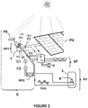
- the means (MP3) for determining the surplus power (P3) of the management device (S) schematically shown in figure 1 may include an electronic microcomputer which receives as input analog information from at least one sensor analog (T1, T2, T3).
- These sensors (T1, T2, T3) transmit, via communication links (F1, F2, F3) shown schematically by broken lines, the electrical intensity I(pe) coming from the control sensor (V), the electrical intensity I (pv) from the photovoltaic panels (PV), and the electrical intensity I (pwm) corresponding to the surplus P3 which is variable and which supplies electrical devices via the inverter (D), these devices being able to be of type AF (power fixed nominal power) or type AV (variable nominal power).
- These communication links (F1, F2, F3) can of course be wired or non-wired, for example by electromagnetic or luminous means.
- the means (MP3) for determining the surplus power P3, whether it is a micro calculator or a simple analog torus as shown in figures 2 And 3 is configured to produce, from the values transmitted by the sensors (T1, T2, T3), in particular electric current values, an analog or digital signal S(i) representative of the value of the surplus (P3) of available power .
- This output signal S(i) of the circuit (MP3) is then transmitted to a transmitter (C1) which in turn transmits it to a receiver (C2) by a connection (Ls) of galvanic, electromagnetic or optical type, schematized by an arrow in figure 1 .
- the receiver (C2) is connected to the input of a means (MPG) for managing the surplus power (P3) available, which will in particular redirect and distribute in real time the surplus power (P3) available, to the various connected electrical devices, in particular devices of the (AV) type with variable consumption power.
- MPG means for managing the surplus power (P3) available, which will in particular redirect and distribute in real time the surplus power (P3) available, to the various connected electrical devices, in particular devices of the (AV) type with variable consumption power.
- the signal S(i) supplied by the circuit (MP3) can be a visual or audible signal
- the means (MPG) for managing the excess power (P3) available is then constituted by a simple manual action of an operator who activates one or more switches to redirect the excess power (P3) available to this or that electrical device (AF, AV) of the system (G).
- said means (MPG) for managing the surplus (P3) of available power is constituted by an electronic automation controlled by the instantaneous value of the surplus (P3) of available power. This automation is then configured to maximize the electrical power (P2) consumed by electrical appliances (AF, AV), and therefore gradually minimize the surplus (P3) of available power.
- this automation is designed to operate or power one or more devices (AF, AV) whose fixed or variable consumption power is compatible with the power (P3) available in surplus, and the choice of said device(s) benefiting from all or part of the excess power (P3) can be done according to a priority grid predefined by the user.
- the means (MPG) for managing the excess power (P3) available is configured to control the modulation of the supply power of the variable power devices (AV2) by a modulated control signal , for example by pulse width modulation (PWM).
- PWM pulse width modulation
- the two cables F1 and F2 are respectively carried by electric currents I(pe) and I(pv) which flow in opposite directions.
- the torus (T) then outputs a signal S(i) proportional to the difference between I(pe) and I(pv).
- the output signal S(i) of the toroid (T) is representative of the power (P3) available in surplus and which is not consumed at time t.
- This information S(i) is transmitted to a transmitter (C1) which passes it on to a receiver (C2) in an electrical, optical or electromagnetic manner.
- the receiver (C2) transmits the information S(i) to the surplus management circuit (MPG) (P3) which can then provide an output voltage to operate gradually by variation of the voltage (possibly of the PWM type - "Pulse Width"). Modulation") or by variation of the intensity, the electrical supply of one or more resistive loads such as for example a heating resistor (R) to heat a water reserve (L) or the charge of a battery ( B) type AF.
- R heating resistor
- L water reserve
- the power consumed by the devices which benefit from a power supply controlled by the circuit (MPG) corresponds to the surplus (P3) of photovoltaic energy available in real time, so that said surplus energy (P3) is used in in whole or in part, for example by devices (AV) with variable consumption power without modifying the current operation of AF devices with fixed consumption power.
- the additional electrical intensity consumed I1(pwm) and extracted from the surplus (P3) then increases the value of the power (P2) consumed at time t, which in turn lowers the value of the surplus power (P3 ) available at time t + delta t. This corresponds to a control which establishes a balance in which the surplus power (P3) available tends to disappear, in favor of an increase in the consumption (P2) of the devices.
- the transmitter (C1) to which the signal S(i) is transmitted at the output of the torus (T) constituting the means (MP3) for determining the surplus (P3) of available power is constituted by a simple LED diode whose brightness varies therefore depending on the surplus (P3) available at each time t.
- the receiver (C2) is made up of a simple photoresistor whose resistance varies depending on the light intensity received from the LED (C1).
- the transmitter (C2) then functions as a potentiometer connected to the input of the surplus management circuit (MPG) (P3).
- MPG surplus management circuit
- the components (C1), (C2) and (MPG) are preferably enclosed in an opaque housing (Bo) so as not to interfere with the optical transmission between the LED (C1) and the photoresistor (C2) with ambient light.
- the electrical intensities I(pe) and I(pv) can be compared mathematically by means of a programmable controller (not shown) which outputs a digital or analog electrical signal S(i), representative of the surplus (P3) of power available at time t and not used.
- the invention makes it possible to provide additional electrical power of photovoltaic origin in a large number of potential applications.
- the interest is to consume the maximum surplus (P3) of available electricity depending on the evolution of the solar conditions of the photovoltaic panels.
- P3 the maximum surplus
- the PWM (Pulse Wave Modulation) technique is ideal, but requires applications that are compatible with variable consumption powers.
- the surface ratio between the solar panels (60 m 2 ) and the reduced photovoltaic surface (180 cm 2 ) is approximately 3300. So when the control photovoltaic surface (V) produces an instantaneous power of 1 W this will indicate that the solar panels ( PV) will be able to produce up to 3300 W at this time.
- the overall electrical intensity Ipv which is produced by the panels (PV) is measured by a toroidal direct current sensor which delivers an intensity proportional to the measured intensity and which is 10 mA per ampere.
- the electrical intensity Iv produced by the control photovoltaic surface (V) is substantially proportional to the solar irradiation of the moment and therefore substantially proportional to the maximum production power of the solar panels (PV).
- the intensities Ipv and Iv are compared by a Hall effect toroid which outputs an electrical signal S(i) which is substantially equal to Ipe - Ipv.
- This signal S(i) represents in proportional value the available photovoltaic energy which is not consumed by the electrical appliances (AF and AV) at the instant considered.
- This signal S(i) controls a PWM type power variator connected to the home's hot water tank so that the stronger the signal S(i), the more the power variator increases the supply power. of the electric water heater in a range of 0 to 2 kW. A temperature probe cuts off this supply as soon as the tank temperature reaches 80°C.
- the battery of the electric car is charged with an intensity which is proportional to Iv, that is to say proportional to the photovoltaic energy available at the moment .
- Iv intensity which is proportional to the photovoltaic energy available at the moment .
- Increasing the energy produced by the panels (PV) (and therefore consumed by the devices) increases the intensity Ipv which reduces the resultant S(i) which makes in turn decrease the control of the PWM power variator.
- This regulation results in an energy balance which shows a total electricity consumption of the connected devices greater than what would have been if the measuring device (S) according to the invention had not been present.
- the maximum power of the panels (PV) was for example 4.5 kW with the washing machine, the refrigerator and the dryer which consumed 3.5 kW.
- the surplus of 1 kW was not usable because in its standard version the water heater would consume 2 kW and the car battery 1.5 kW. Thanks to the device (S) according to the invention the surplus of 1 kW was gradually distributed by the variable power generator PWM to the water heater and to the battery.
- the invention responds well to the objectives set. It is particularly simple and economical to implement, using only a few inexpensive components: a small photovoltaic control surface, a direct current toroid, a few resistors, an LED, a photoresistor, possibly a microcontroller.
- the invention makes it possible to recover, use or store more energy than in the absence of the device (S) making it possible to use a surplus of available power, which can lead either to producing and using more electrical energy at from a given dimensioning of a photovoltaic generator (G), or to propose a more modest and less costly dimensioning of a photovoltaic installation, taking into account the increased efficiency of electrical energy production.
- the invention is particularly well suited to a device (G) for producing photovoltaic energy which is not connected to a public electricity network, for which the state of the art does not make it possible to determine and exploit a surplus of photovoltaic power. This situation is still largely the case in a large number of developing countries, and is even spreading in developed countries in a population seeking energy autonomy.
Landscapes
- Engineering & Computer Science (AREA)
- Power Engineering (AREA)
- Control Of Electrical Variables (AREA)
- Photovoltaic Devices (AREA)
Claims (26)
- Vorrichtung (S) zur Verwaltung eines Überschusses (P3) an Photovoltaikleistung, der an den Anschlüssen eines Photovoltaikgenerators (DE) verfügbar ist, der mit Photovoltaikpaneelen (PV) ausgestattet ist, die Elektrogeräte (AF) mit fester Leistung und Elektrogeräte (AV) die an den Photovoltaikgenerator (DE) angeschlossen sind mit Strom mit variabler Leistung versorgen können, wobei die überschüssige Leistung (P3) zu jedem Zeitpunkt t der Differenz zwischen der maximalen potenziellen elektrischen Leistung (P1), die von dem Photovoltaikgenerator (DE) erzeugt werden könnte bezüglich seiner Beleuchtung und der elektrischen Leistung (P2), die zu jedem Zeitpunkt t von den Elektrogeräten (AF, AV) tatsächlich verbraucht wird, dadurch gekennzeichnet, dass es Folgendes umfasst:- einen photoelektrischen Kontrollsensor (PE), der in der Lage ist, zu jedem Zeitpunkt die von den Photovoltaikpaneelen (PV) empfangene Sonnenlichtintensität zu messen, um daraus die maximale potenzielle elektrische Leistung (P1) abzuleiten;- ein Mittel (MP3) zur Bestimmung der überschüssigen Leistung (P3), die zu diesem Zeitpunkt t verfügbar ist, durch Vergleich zwischen dem Wert der maximal möglichen elektrischen Leistung (P1) und dem Wert der tatsächlich von den Elektrogeräten verbrauchten elektrischen Leistung (P2) ( AF; AV), wobei das Mittel (MP3) einen elektronischen Mikrocomputer umfasst, der als Eingabe analoge Informationen von mindestens einem analogen Sensor (T1, T2, T3) empfängt, der mit einem Hall-Effekt-Torus ausgestattet ist;- und ein Mittel (MPG) zum Verwalten der verfügbaren überschüssigen Leistung (P3), das so konfiguriert ist, dass es die verfügbare überschüssige Leistung (P3) zwischen den elektrischen Geräten (AF, AV) umleitet und verteilt, um die Nutzung der überschüssigen Leistung (P3) die and an den Klemmen des Photovoltaikgenerators (DE) verfügbar ist, zu maximieren.
- Vorrichtung (S) nach Anspruch 1, dadurch gekennzeichnet, dass das Mittel (MPG) zur Verwaltung überschüssiger Leistung (P3) dazu ausgelegt ist, die Inbetriebnahme und Stromversorgung mindestens eines zusätzliches Elektrogeräts (AF) oder die Erhöhung des Verbrauchs eines bereits an den Photovoltaikgenerator (DE) angeschlossenen Elektrogeräts (AF, AV).
- Vorrichtung (S) nach Anspruch 1 oder Anspruch 2, dadurch gekennzeichnet, dass der photoelektrische Anzeigesensor (PE) so konfiguriert ist, dass er die von den Photovoltaikpaneelen (PV) empfangene Sonnenlichtintensität misst und einen zu dieser Licht Intensität proportionalen elektrischen Strom erzeugt und daher proportional zur maximalen potenziellen Leistung (P1), die der Photovoltaikgenerator (DE) zu jedem Zeitpunkt t erzeugen könnte.
- Vorrichtung (S) nach einem der vorhergehenden Ansprüche, dadurch gekennzeichnet, dass der fotoelektrische Anzeigesensor (PE) ein Fotowiderstand, ein Fototransistor, eine Fotodiode, ein Pyranometer oder eine fotovoltaische Anzeigefläche (V) ist.
- Vorrichtung (S) nach Anspruch 4, dadurch gekennzeichnet, dass der photoelektrische Steuersensor (PE) aus einer Photovoltaikfläche (V) besteht, die insgesamt aus einer einzelnen Photovoltaikzelle oder aus mehreren in Reihe oder parallel geschalteten Photovoltaikzellen besteht einer Größe kleiner als die der Photovoltaik-Paneele (PV) und parallel zur Oberfläche der Photovoltaik-Paneele (PV) ausgerichtet, um die gleiche Lichtintensität wie die Photovoltaik-Paneele (PV) zu empfangen und eine elektrische Leistung (P4) zu erzeugen die ihrer maximal möglichen Leistung (P1) darstellt.
- Vorrichtung (S) nach Anspruch 5, dadurch gekennzeichnet, dass die an den Anschlüssen der Steuer-Photovoltaikfläche (V) gemessene Leistung (P4) und die berechnete maximale potenzielle Leistung (P1) der Solarpaneele (PV) miteinander verknüpft sind über eine mathematische Beziehung vom Typ: P1 = (x. P4) + z, wobei x und z feste Werte sind, die von den geometrischen und photoelektrischen Eigenschaften der Paneele (PV) und der besagten photovoltaischen Oberfläche (V) abhängen.
- Vorrichtung (S) nach einem der vorhergehenden Ansprüche, dadurch gekennzeichnet, dass der mindestens eine mit einem Hall-Effekt-Torus versehene analoge Sensor (T1, T2, T3) so positioniert ist, dass er die elektrischen Intensitäten I (pe), I(pv) und I(pwm) erfasst, die jeweils durch den Anzeigesensor (PE), die Photovoltaikpaneele (PV) und die Elektrogeräte (AF, AV) laufen, wobei der elektronische Mikrocomputer (MP3) so konfiguriert ist, dass er ein analoges oder ein digitales Signal S(i) erzeugt, das den Wert der verfügbaren überschüssigen Leistung (P3) darstellt.
- Vorrichtung (S) nach einem der vorhergehenden Ansprüche, dadurch gekennzeichnet, dass die Mittel (MP3) zur Bestimmung der zu jedem Zeitpunkt t verfügbaren überschüssigen Leistung (P3) einen analogen Sensor (T) umfassen, der aus einem einzelnen Torus mit Hall-Effekt besteht der von einem von den Photovoltaikmodulen (PV) kommenden ersten elektrischen Leiter (F2) gekreuzt ist und von einem elektrischen Strom I (pv) durchflossen wird, als auch von einem zweiten elektrischen Leiter (F1), der von der photoelektrischen Steuerkomponente (PE) kommt und der von einem von der photoelektrischen Komponente (PE) erzeugter Strom I(p) durchflossen wird der die Sonnenhelligkeit misst, wobei der Hall-Effekt-Torus (T) am Ausgang ein elektrisches Signal S(i) erzeugt, das die zu jedem Zeitpunkt t verfügbare überschüssige Leistung (P3) darstellt.
- Vorrichtung (S) nach Anspruch 8, dadurch gekennzeichnet, dass der Hall-Effekt-Torus (T) außerdem von einem dritten elektrischen Leiter (F3) durchzogen ist, der vom Strom I (pwm) zur Versorgung der elektrischen Geräte (AV) mit variabler Leistung durchflossen wird.
- Vorrichtung (S) nach Anspruch 8 oder Anspruch 9, dadurch gekennzeichnet, dass die photovoltaische Steuerfläche (V) mit den Enden eines leitenden Drahtes (F1) verbunden ist, der vorzugsweise einen geringen elektrischen Widerstand aufweist und durch den Torus (T) in mehreren N Wicklungen verläuft, so dass die elektrische Intensität I(p), die durch den leitfähigen Draht (F1) fließt, am Ausgang des Torus (T) mit N multipliziert wird.
- Gerät (S) nach einem der vorhergehenden Ansprüche, dadurch gekennzeichnet, dass das Mittel (MPG) zur Verwaltung der verfügbaren überschüssigen Leistung (P3) aus einer manuellen Aktion eines Bedieners gemäß einer Angabe des Geräts (S) des Vorhandenseins eines Überschusses an verfügbarer Leistung (P3), besteht.
- Vorrichtung (S) nach einem der Ansprüche 1 bis 10, dadurch gekennzeichnet, dass das Mittel (MPG) zur Verwaltung der verfügbaren überschüssigen Leistung (P3) aus einer elektronischen Automatisierung besteht, die an den Momentanwert der verfügbare überschüssigen Leistung (P3) gekoppelt ist, wobei die Automatisierung so konfiguriert ist, dass sie den Überschuss (P3) der verfügbaren elektrischen Leistung minimiert und die von den Elektrogeräten (AF, AV) verbrauchte elektrische Leistung (P2) maximiert.
- Gerät (S) nach Anspruch 12, dadurch gekennzeichnet, dass die Automatisierung dazu ausgelegt ist, ein oder mehrere elektrische Geräte (AF, AV) zu betreiben oder mit Strom zu versorgen, deren fester oder variabler Leistungsverbrauch mit dem Überschuss (P3) der verfügbaren Leistung kompatibel ist, und die Geräte auszuwählen, die von der gesamten oder einem Teil des Überschusses (P3) der verfügbaren Leistung profitieren, gemäß einem vom Benutzer vordefinierten Prioritätsraster.
- Vorrichtung (S) nach einem der Ansprüche 11 bis 13, dadurch gekennzeichnet, dass die Mittel (MPG) zur Verwaltung des Überschusses (P3) der verfügbaren Leistung einen Schaltkreis zur Steuerung von Elektrogeräten mit variabler Leistung (AV) umfassen, der den Wert (P3) der verfügbaren Leistung Überschuss bekommt über einen Sender (C1) und einen Empfänger (C2) die in das Gerät (S) integriert und über eine Kommunikationsverbindung elektrischer, elektromagnetischer oder leuchtender Art verbunden sind.
- Vorrichtung (S) nach Anspruch 14, dadurch gekennzeichnet, dass die Steuerschaltung der Mittel (MPG) zur Verwaltung des Überschusses (P3) an verfügbarer Leistung so konfiguriert ist, dass sie die Modulation der Stromversorgung der Leistungsgeräte variabel (AV) steuert, beispielsweise durch Pulsweitenmodulation (PWM).
- System (G), das einen mit Photovoltaikpaneelen (PV) ausgestatteten Photovoltaikgenerator (DE) umfasst, der Elektrogeräte (AF) mit fester Leistung oder Elektrogeräte (AV) mit variabler Leistung versorgt, dadurch gekennzeichnet, dass es eine Vorrichtung (S) umfasst für die Verwaltung eines Überschusses (P3) an Photovoltaikleistung, der an den Anschlüssen eines Photovoltaikgenerators gemäß einem der vorhergehenden Ansprüche verfügbar ist, um die Nutzung eines zu einem Zeitpunkt t an den Anschlüssen des Photovoltaikgenerator (DE) verfügbaren Überschusses (P3) an Photovoltaikleistung zu maximieren.
- System (G) nach Anspruch 16, dadurch gekennzeichnet, dass es einen Wechselrichter (D) umfasst, der zwischen den Photovoltaikpaneelen (PV) und den elektrischen Geräten (AF, AV) angeschlossen ist, und dass der Ausgang des Wechselrichters (D) über die Einrichtung (S) zur Bewirtschaftung des Überschusses (P3) an Photovoltaikleistung mit den Elektrogeräten (AV) mit variabler Leistungsversorgung verbunden ist, so dass die Elektrogeräte (AV) mit variabler Leistung in Abhängigkeit vom Überschuss (P3) elektrisch versorgt werden der zu jedem Zeitpunkt t verfügbaren Leistung.
- System (G) nach Anspruch 16 oder Anspruch 17, dadurch gekennzeichnet, dass die Komponenten der genannten Verwaltungsvorrichtung (S) des Überschusses (P3) an verfügbarer Leistung direkt in den genannten Wechselrichter (D) integriert sind, mit Ausnahme der photoelektrischer Sensor (PE), der weiterhin dem gleichen Sonnenlicht ausgesetzt ist wie die Photovoltaikmodule (PV).
- System (G) nach einem der Ansprüche 16 bis 18, dadurch gekennzeichnet, dass die elektrischen Geräte (AV) mit variabler Stromversorgung Geräte wie Hydraulikpumpen, Heizwiderstände, Kühlaggregate, Ventilatoren, Generatoren für atmosphärisches Wasser, Raumentfeuchter, Redox-Flow-Batterien, Batterien für Elektrofahrzeuge, Wasserstoffzellen, umfassen.
- System (G) nach einem der Ansprüche 16 bis 19, dadurch gekennzeichnet, dass es ein erstes Gerät vom Typ MPPT ("Maximum Power Point Tracking"), das zwischen den Solarpaneelen (PV) und dem Wechselrichter (D) angeordnet ist, und ein zweites MPPT-Gerät umfasst, angeordnet zwischen dem fotoelektrischen Anzeigesensor (PE) und den Mitteln (MP3) zur Bestimmung des Überschusses (P3) der verfügbaren Leistung.
- System (G) nach einem der Ansprüche 16 bis 20, dadurch gekennzeichnet, dass mindestens eines der genannten elektrischen Geräte für einen Teil vom Typ (AF) mit fester Stromversorgung ist und für einen anderen Teil vom Typ (AV) mit variabler Leistung Versorgung ist, wie zum Beispiel einen atmosphärischen Wassergenerator, der teilweise aus einem atmosphärischen Entfeuchter besteht, der das atmosphärische Wasser in einem Tank kondensiert und im variablen Stromversorgungsmodus (AV) arbeitet, und zum anderen Teil aus einem System zur Filterung und Reinigung des gesammelten Wassers besteht in dem Tank, und das im festen Stromversorgungsmodus (AF) arbeitet.
- System (G) nach einem der Ansprüche 16 bis 21, dadurch gekennzeichnet, dass die elektrischen Geräte (AF, AV) so dimensioniert sind, dass sie die gesamte potenzielle elektrische Leistung (P1) verbrauchen können, die von den Photovoltaikpaneelen erzeugt wird (PV), einschließlich der zu jedem Zeitpunkt t verfügbaren Überschussleistung (P3).
- System (G) nach einem der Ansprüche 16 bis 22, dadurch gekennzeichnet, dass es entweder an einem isolierten Standort ohne Möglichkeit zur Übertragung von elektrischem Strom mit einem öffentlichen elektrischen Energieverteilungsnetz angeordnet oder an ein öffentliches elektrisches Energieverteilungsnetz angeschlossen ist um bei Bedarf den Empfang von zusätzlichem Strom aus dem öffentlichen Stromverteilungsnetz oder die Einspeisung der gesamten oder eines Teils der von der Verwaltungsvorrichtung (S) gemessenen oder berechneten überschüssigen Leistung (P3) in das öffentliche Netz zu ermöglichen.
- Wechselrichtergerät, das in der Lage ist, einen von einem Photovoltaikgenerator gelieferten Gleichstrom in einen Wechselstrom umzuwandeln, der zur Versorgung von Elektrogeräten (AF, AV) bestimmt ist, dadurch gekennzeichnet, dass es eine Vorrichtung (S) zur Verwaltung der überschüssigen (P3) verfügbaren Leistung integriert nach einen der Ansprüche 1 bis 15.
- Verfahren zur Verwaltung eines Überschusses (P3) an elektrischer Leistung, der an den Anschlüssen eines Photovoltaikgenerators verfügbar ist, unter Verwendung einer Verwaltungsvorrichtung nach Anspruch 1, dadurch gekennzeichnet, dass es Schritte umfasst, die aus Folgendem bestehen:- Bestimmung der maximalen potenziellen Leistung (P1), die der Photovoltaikgenerator zu jedem Zeitpunkt t liefern kann, abhängig von der zu diesem Zeitpunkt empfangenen Sonneneinstrahlung;- Bestimmung der Leistung (P2), die zum Zeitpunkt t von allen an den Photovoltaikgenerator angeschlossenen elektrischen Geräten (AF, AV) verbraucht wird;- Bestimmung eines Überschusses an Leistung (P3), der zum Zeitpunkt t verfügbar ist, entsprechend der Differenz P1 - P2;- Im Falle eines positiven Überschusswerts (P3) der verfügbaren Leistung mindestens ein elektrisches Gerät aktivieren und/oder mit Strom versorgen, um den Wert der verbrauchten Leistung (P2) zu maximieren und den Wert des an einem späteren Zeitpunkt t + delta t verfügbaren Überschusses (P3) zu minimieren.
- Verfahren nach dem vorhergehenden Anspruch, dadurch gekennzeichnet, dass es mit der Vorrichtung (S) zur Verwaltung überschüssiger verfügbarer Leistung (P3) nach einem der Ansprüche 1 bis 15, oder mit einem System (G) nach einem der Ansprüche 16 bis 23 durchgeführt wird.
Priority Applications (1)
| Application Number | Priority Date | Filing Date | Title |
|---|---|---|---|
| MA64741A MA64741B1 (fr) | 2020-08-19 | 2021-08-17 | Dispositif et procédé pour déterminer et utiliser un surplus de puissance électrique disponible généré par un générateur solaire photovoltaïque |
Applications Claiming Priority (2)
| Application Number | Priority Date | Filing Date | Title |
|---|---|---|---|
| FR2008557A FR3113525B1 (fr) | 2020-08-19 | 2020-08-19 | Dispositif de mesure et/ou de calcul en continu de la puissance électrique théorique que peut produire un générateur d'énergie solaire photovoltaïque et son application en matière de gestion du surplus d'énergie non utilisé |
| PCT/FR2021/000094 WO2022038319A1 (fr) | 2020-08-19 | 2021-08-17 | Dispositif et procédé pour déterminer et utiliser un surplus de puissance électrique disponible généré par un générateur solaire photovoltaïque |
Publications (3)
| Publication Number | Publication Date |
|---|---|
| EP4200976A1 EP4200976A1 (de) | 2023-06-28 |
| EP4200976B1 true EP4200976B1 (de) | 2024-08-07 |
| EP4200976C0 EP4200976C0 (de) | 2024-08-07 |
Family
ID=73013746
Family Applications (1)
| Application Number | Title | Priority Date | Filing Date |
|---|---|---|---|
| EP21782772.4A Active EP4200976B1 (de) | 2020-08-19 | 2021-08-17 | Vorrichtung und verfahren zur bestimmung und verwendung eines überschusses an verfügbarer, von einem solarfotovoltaischen generator erzeugter elektrischer energie |
Country Status (9)
| Country | Link |
|---|---|
| US (1) | US12160198B2 (de) |
| EP (1) | EP4200976B1 (de) |
| CN (1) | CN116325487A (de) |
| AU (1) | AU2021328698A1 (de) |
| ES (1) | ES2994215T3 (de) |
| FR (1) | FR3113525B1 (de) |
| MA (1) | MA64741B1 (de) |
| WO (1) | WO2022038319A1 (de) |
| ZA (1) | ZA202304434B (de) |
Families Citing this family (6)
| Publication number | Priority date | Publication date | Assignee | Title |
|---|---|---|---|---|
| FR3137929B1 (fr) * | 2022-07-13 | 2025-04-04 | Joel Gilbert | Générateur d'eau atmosphérique alimenté par l'énergie solaire photovoltaïque |
| FR3153203A1 (fr) * | 2023-09-14 | 2025-03-21 | Joel Gilbert | Adaptateur Off-Grid pour routeur solaire photovoltaïque On-Grid |
| CN117318054B (zh) * | 2023-11-28 | 2024-03-15 | 深圳安培时代数字能源科技有限公司 | 光伏电能处理方法及相关装置 |
| CN118412909B (zh) * | 2024-07-01 | 2025-02-14 | 浙江艾罗网络能源技术股份有限公司 | 储能充电系统及控制方法 |
| CN118655396B (zh) * | 2024-08-12 | 2024-11-26 | 中汽数据(天津)有限公司 | 应用太阳能光伏车顶的电池能耗节约量的测试方法和装置 |
| CN118899855B (zh) * | 2024-09-27 | 2025-01-24 | 浙江追求电机股份有限公司 | 一种供电装置、供电系统及数据中心 |
Family Cites Families (4)
| Publication number | Priority date | Publication date | Assignee | Title |
|---|---|---|---|---|
| JP5162737B2 (ja) * | 2006-05-17 | 2013-03-13 | 英弘精機株式会社 | 太陽電池の特性評価装置 |
| WO2014081967A1 (en) * | 2012-11-21 | 2014-05-30 | Atonometrics, Inc. | Soiling measurement system for photovoltaic arrays |
| JP6474305B2 (ja) * | 2015-04-23 | 2019-02-27 | 株式会社日立製作所 | 太陽光発電システムの診断方法及び監視装置 |
| KR20190072084A (ko) * | 2017-12-15 | 2019-06-25 | (주)대은 | 실시간 태양광발전 상황에 따른 에너지저장장치 운영시스템 및 방법 |
-
2020
- 2020-08-19 FR FR2008557A patent/FR3113525B1/fr active Active
-
2021
- 2021-08-17 MA MA64741A patent/MA64741B1/fr unknown
- 2021-08-17 ES ES21782772T patent/ES2994215T3/es active Active
- 2021-08-17 WO PCT/FR2021/000094 patent/WO2022038319A1/fr not_active Ceased
- 2021-08-17 EP EP21782772.4A patent/EP4200976B1/de active Active
- 2021-08-17 US US18/042,060 patent/US12160198B2/en active Active
- 2021-08-17 AU AU2021328698A patent/AU2021328698A1/en active Pending
- 2021-08-17 CN CN202180071139.3A patent/CN116325487A/zh active Pending
-
2023
- 2023-04-14 ZA ZA2023/04434A patent/ZA202304434B/en unknown
Also Published As
| Publication number | Publication date |
|---|---|
| FR3113525A1 (fr) | 2022-02-25 |
| US12160198B2 (en) | 2024-12-03 |
| AU2021328698A9 (en) | 2024-05-23 |
| US20230318528A1 (en) | 2023-10-05 |
| MA64741B1 (fr) | 2024-12-31 |
| ZA202304434B (en) | 2024-09-25 |
| AU2021328698A1 (en) | 2023-04-27 |
| CN116325487A (zh) | 2023-06-23 |
| ES2994215T3 (en) | 2025-01-20 |
| FR3113525B1 (fr) | 2022-07-22 |
| WO2022038319A1 (fr) | 2022-02-24 |
| EP4200976C0 (de) | 2024-08-07 |
| EP4200976A1 (de) | 2023-06-28 |
Similar Documents
| Publication | Publication Date | Title |
|---|---|---|
| EP4200976B1 (de) | Vorrichtung und verfahren zur bestimmung und verwendung eines überschusses an verfügbarer, von einem solarfotovoltaischen generator erzeugter elektrischer energie | |
| EP3676541B1 (de) | Heizgerät mit einer batterie und einem wechselrichter zum zuführen von energie von der batterie in die elektrische versorgungsquelle | |
| EP3117158B1 (de) | Elektro-wassererwärmer mit einstellbarer leistung | |
| FR2960099A1 (fr) | Systeme de recuperation d'energie renouvelable | |
| US20150189705A1 (en) | Device for generating electricity by harnessing solar energy and method thereof | |
| EP3065021A1 (de) | Warmwasserheizsystem mit dedizierter fotovoltaikanlage | |
| EP2237387B1 (de) | Power supply system and charging control method for electrochemical generators | |
| CA3044348C (fr) | Appareil de chauffage de type radiateur electrique incluant un convertisseur de tension | |
| OA21174A (fr) | Dispositif et procédé pour déterminer et utiliser un surplus de puissance électrique disponible généré par un générateur solaire photovoltaïque. | |
| EP3190681B1 (de) | Verfahren und vorrichtung zum aufladen einer batterie | |
| Patil et al. | A proficient solar panel efficiency measurement system: Using current measurements | |
| EP3053243B1 (de) | Elektrisch autonome anlage und verfahren zur verwaltung | |
| WO2016142628A1 (fr) | Carte électronique de pilotage énergétique d'un équipement électrique autonome et communicant | |
| EP4372183A1 (de) | System und verfahren zur temperierung eines badebeckens | |
| EP4308859B1 (de) | System zur verwaltung einer gleichstromquelle mit variabler leistung | |
| EP3123583A1 (de) | Mono-inverter | |
| FR3153203A1 (fr) | Adaptateur Off-Grid pour routeur solaire photovoltaïque On-Grid | |
| FR3075322A1 (fr) | Appareil de chauffage assurant une modulation continue de la puissance d’alimentation de la resistance electrique | |
| FR3113722A1 (fr) | Chauffe-eau électrique instantané incluant deux types de résistance de chauffage et installation comprenant un tel chauffe-eau | |
| FR3039720B1 (fr) | Procede de gestion du courant produit par des panneaux | |
| WO2014199052A2 (fr) | Procede dynamique de decharge d'un accumulateur recharge par une source d'energie renouvelable | |
| FR3004021A1 (fr) | Systeme automatique de gestion de la production et de la consommation d'electricite. |
Legal Events
| Date | Code | Title | Description |
|---|---|---|---|
| STAA | Information on the status of an ep patent application or granted ep patent |
Free format text: STATUS: UNKNOWN |
|
| STAA | Information on the status of an ep patent application or granted ep patent |
Free format text: STATUS: THE INTERNATIONAL PUBLICATION HAS BEEN MADE |
|
| PUAI | Public reference made under article 153(3) epc to a published international application that has entered the european phase |
Free format text: ORIGINAL CODE: 0009012 |
|
| STAA | Information on the status of an ep patent application or granted ep patent |
Free format text: STATUS: REQUEST FOR EXAMINATION WAS MADE |
|
| 17P | Request for examination filed |
Effective date: 20230317 |
|
| AK | Designated contracting states |
Kind code of ref document: A1 Designated state(s): AL AT BE BG CH CY CZ DE DK EE ES FI FR GB GR HR HU IE IS IT LI LT LU LV MC MK MT NL NO PL PT RO RS SE SI SK SM TR |
|
| DAX | Request for extension of the european patent (deleted) | ||
| RAV | Requested validation state of the european patent: fee paid |
Extension state: TN Effective date: 20230317 Extension state: MA Effective date: 20230317 |
|
| REG | Reference to a national code |
Ref country code: DE Ref legal event code: R079 Free format text: PREVIOUS MAIN CLASS: H02S0050000000 Ipc: H01L0027146000 Ref country code: DE Ref legal event code: R079 Ref document number: 602021016962 Country of ref document: DE Free format text: PREVIOUS MAIN CLASS: H02S0050000000 Ipc: H01L0027146000 |
|
| GRAP | Despatch of communication of intention to grant a patent |
Free format text: ORIGINAL CODE: EPIDOSNIGR1 |
|
| STAA | Information on the status of an ep patent application or granted ep patent |
Free format text: STATUS: GRANT OF PATENT IS INTENDED |
|
| RIC1 | Information provided on ipc code assigned before grant |
Ipc: H01L 27/146 20060101AFI20240227BHEP |
|
| INTG | Intention to grant announced |
Effective date: 20240314 |
|
| GRAS | Grant fee paid |
Free format text: ORIGINAL CODE: EPIDOSNIGR3 |
|
| GRAA | (expected) grant |
Free format text: ORIGINAL CODE: 0009210 |
|
| STAA | Information on the status of an ep patent application or granted ep patent |
Free format text: STATUS: THE PATENT HAS BEEN GRANTED |
|
| AK | Designated contracting states |
Kind code of ref document: B1 Designated state(s): AL AT BE BG CH CY CZ DE DK EE ES FI FR GB GR HR HU IE IS IT LI LT LU LV MC MK MT NL NO PL PT RO RS SE SI SK SM TR |
|
| REG | Reference to a national code |
Ref country code: GB Ref legal event code: FG4D Free format text: NOT ENGLISH |
|
| REG | Reference to a national code |
Ref country code: CH Ref legal event code: EP |
|
| REG | Reference to a national code |
Ref country code: IE Ref legal event code: FG4D Free format text: LANGUAGE OF EP DOCUMENT: FRENCH |
|
| REG | Reference to a national code |
Ref country code: DE Ref legal event code: R096 Ref document number: 602021016962 Country of ref document: DE |
|
| U01 | Request for unitary effect filed |
Effective date: 20240821 |
|
| U07 | Unitary effect registered |
Designated state(s): AT BE BG DE DK EE FI FR IT LT LU LV MT NL PT RO SE SI Effective date: 20240902 |
|
| U20 | Renewal fee for the european patent with unitary effect paid |
Year of fee payment: 4 Effective date: 20240919 |
|
| REG | Reference to a national code |
Ref country code: MA Ref legal event code: VAGR Ref document number: 64741 Country of ref document: MA Kind code of ref document: B1 |
|
| PG25 | Lapsed in a contracting state [announced via postgrant information from national office to epo] |
Ref country code: NO Free format text: LAPSE BECAUSE OF FAILURE TO SUBMIT A TRANSLATION OF THE DESCRIPTION OR TO PAY THE FEE WITHIN THE PRESCRIBED TIME-LIMIT Effective date: 20241107 |
|
| PG25 | Lapsed in a contracting state [announced via postgrant information from national office to epo] |
Ref country code: GR Free format text: LAPSE BECAUSE OF FAILURE TO SUBMIT A TRANSLATION OF THE DESCRIPTION OR TO PAY THE FEE WITHIN THE PRESCRIBED TIME-LIMIT Effective date: 20241108 Ref country code: PL Free format text: LAPSE BECAUSE OF FAILURE TO SUBMIT A TRANSLATION OF THE DESCRIPTION OR TO PAY THE FEE WITHIN THE PRESCRIBED TIME-LIMIT Effective date: 20240807 |
|
| REG | Reference to a national code |
Ref country code: ES Ref legal event code: FG2A Ref document number: 2994215 Country of ref document: ES Kind code of ref document: T3 Effective date: 20250120 |
|
| PG25 | Lapsed in a contracting state [announced via postgrant information from national office to epo] |
Ref country code: IS Free format text: LAPSE BECAUSE OF FAILURE TO SUBMIT A TRANSLATION OF THE DESCRIPTION OR TO PAY THE FEE WITHIN THE PRESCRIBED TIME-LIMIT Effective date: 20241207 |
|
| PG25 | Lapsed in a contracting state [announced via postgrant information from national office to epo] |
Ref country code: HR Free format text: LAPSE BECAUSE OF FAILURE TO SUBMIT A TRANSLATION OF THE DESCRIPTION OR TO PAY THE FEE WITHIN THE PRESCRIBED TIME-LIMIT Effective date: 20240807 |
|
| PG25 | Lapsed in a contracting state [announced via postgrant information from national office to epo] |
Ref country code: RS Free format text: LAPSE BECAUSE OF FAILURE TO SUBMIT A TRANSLATION OF THE DESCRIPTION OR TO PAY THE FEE WITHIN THE PRESCRIBED TIME-LIMIT Effective date: 20241107 |
|
| PG25 | Lapsed in a contracting state [announced via postgrant information from national office to epo] |
Ref country code: RS Free format text: LAPSE BECAUSE OF FAILURE TO SUBMIT A TRANSLATION OF THE DESCRIPTION OR TO PAY THE FEE WITHIN THE PRESCRIBED TIME-LIMIT Effective date: 20241107 Ref country code: PL Free format text: LAPSE BECAUSE OF FAILURE TO SUBMIT A TRANSLATION OF THE DESCRIPTION OR TO PAY THE FEE WITHIN THE PRESCRIBED TIME-LIMIT Effective date: 20240807 Ref country code: NO Free format text: LAPSE BECAUSE OF FAILURE TO SUBMIT A TRANSLATION OF THE DESCRIPTION OR TO PAY THE FEE WITHIN THE PRESCRIBED TIME-LIMIT Effective date: 20241107 Ref country code: IS Free format text: LAPSE BECAUSE OF FAILURE TO SUBMIT A TRANSLATION OF THE DESCRIPTION OR TO PAY THE FEE WITHIN THE PRESCRIBED TIME-LIMIT Effective date: 20241207 Ref country code: HR Free format text: LAPSE BECAUSE OF FAILURE TO SUBMIT A TRANSLATION OF THE DESCRIPTION OR TO PAY THE FEE WITHIN THE PRESCRIBED TIME-LIMIT Effective date: 20240807 Ref country code: GR Free format text: LAPSE BECAUSE OF FAILURE TO SUBMIT A TRANSLATION OF THE DESCRIPTION OR TO PAY THE FEE WITHIN THE PRESCRIBED TIME-LIMIT Effective date: 20241108 |
|
| U1O | Appointed representative for the unitary patent procedure deleted after the registration of the unitary effect | ||
| PG25 | Lapsed in a contracting state [announced via postgrant information from national office to epo] |
Ref country code: SM Free format text: LAPSE BECAUSE OF FAILURE TO SUBMIT A TRANSLATION OF THE DESCRIPTION OR TO PAY THE FEE WITHIN THE PRESCRIBED TIME-LIMIT Effective date: 20240807 |
|
| PG25 | Lapsed in a contracting state [announced via postgrant information from national office to epo] |
Ref country code: CZ Free format text: LAPSE BECAUSE OF FAILURE TO SUBMIT A TRANSLATION OF THE DESCRIPTION OR TO PAY THE FEE WITHIN THE PRESCRIBED TIME-LIMIT Effective date: 20240807 |
|
| PG25 | Lapsed in a contracting state [announced via postgrant information from national office to epo] |
Ref country code: SK Free format text: LAPSE BECAUSE OF FAILURE TO SUBMIT A TRANSLATION OF THE DESCRIPTION OR TO PAY THE FEE WITHIN THE PRESCRIBED TIME-LIMIT Effective date: 20240807 |
|
| PLBE | No opposition filed within time limit |
Free format text: ORIGINAL CODE: 0009261 |
|
| STAA | Information on the status of an ep patent application or granted ep patent |
Free format text: STATUS: NO OPPOSITION FILED WITHIN TIME LIMIT |
|
| PG25 | Lapsed in a contracting state [announced via postgrant information from national office to epo] |
Ref country code: MC Free format text: LAPSE BECAUSE OF FAILURE TO SUBMIT A TRANSLATION OF THE DESCRIPTION OR TO PAY THE FEE WITHIN THE PRESCRIBED TIME-LIMIT Effective date: 20240807 |
|
| 26N | No opposition filed |
Effective date: 20250508 |
|
| PG25 | Lapsed in a contracting state [announced via postgrant information from national office to epo] |
Ref country code: IE Free format text: LAPSE BECAUSE OF NON-PAYMENT OF DUE FEES Effective date: 20240817 |
|
| U20 | Renewal fee for the european patent with unitary effect paid |
Year of fee payment: 5 Effective date: 20250723 |
|
| PGFP | Annual fee paid to national office [announced via postgrant information from national office to epo] |
Ref country code: ES Payment date: 20250901 Year of fee payment: 5 |
|
| PGFP | Annual fee paid to national office [announced via postgrant information from national office to epo] |
Ref country code: GB Payment date: 20250725 Year of fee payment: 5 |
|
| PGFP | Annual fee paid to national office [announced via postgrant information from national office to epo] |
Ref country code: CH Payment date: 20250901 Year of fee payment: 5 |
|
| VSFP | Annual fee paid to validation state [announced via postgrant information from national office to epo] |
Ref country code: MA Payment date: 20241122 Year of fee payment: 4 Ref country code: MA Payment date: 20250819 Year of fee payment: 5 |
|
| PG25 | Lapsed in a contracting state [announced via postgrant information from national office to epo] |
Ref country code: CY Free format text: LAPSE BECAUSE OF FAILURE TO SUBMIT A TRANSLATION OF THE DESCRIPTION OR TO PAY THE FEE WITHIN THE PRESCRIBED TIME-LIMIT; INVALID AB INITIO Effective date: 20210817 |