EP4200554B1 - System und verfahren zur digitalen überwachung eines druckbehälters - Google Patents
System und verfahren zur digitalen überwachung eines druckbehälters Download PDFInfo
- Publication number
- EP4200554B1 EP4200554B1 EP21765645.3A EP21765645A EP4200554B1 EP 4200554 B1 EP4200554 B1 EP 4200554B1 EP 21765645 A EP21765645 A EP 21765645A EP 4200554 B1 EP4200554 B1 EP 4200554B1
- Authority
- EP
- European Patent Office
- Prior art keywords
- pressure vessel
- gas
- unit
- sensor
- composite pressure
- Prior art date
- Legal status (The legal status is an assumption and is not a legal conclusion. Google has not performed a legal analysis and makes no representation as to the accuracy of the status listed.)
- Active
Links
Images


Classifications
-
- F—MECHANICAL ENGINEERING; LIGHTING; HEATING; WEAPONS; BLASTING
- F17—STORING OR DISTRIBUTING GASES OR LIQUIDS
- F17C—VESSELS FOR CONTAINING OR STORING COMPRESSED, LIQUEFIED OR SOLIDIFIED GASES; FIXED-CAPACITY GAS-HOLDERS; FILLING VESSELS WITH, OR DISCHARGING FROM VESSELS, COMPRESSED, LIQUEFIED, OR SOLIDIFIED GASES
- F17C13/00—Details of vessels or of the filling or discharging of vessels
- F17C13/02—Special adaptations of indicating, measuring, or monitoring equipment
- F17C13/021—Special adaptations of indicating, measuring, or monitoring equipment having the height as the parameter
-
- G—PHYSICS
- G01—MEASURING; TESTING
- G01F—MEASURING VOLUME, VOLUME FLOW, MASS FLOW OR LIQUID LEVEL; METERING BY VOLUME
- G01F23/00—Indicating or measuring liquid level or level of fluent solid material, e.g. indicating in terms of volume or indicating by means of an alarm
- G01F23/22—Indicating or measuring liquid level or level of fluent solid material, e.g. indicating in terms of volume or indicating by means of an alarm by measuring physical variables, other than linear dimensions, pressure or weight, dependent on the level to be measured, e.g. by difference of heat transfer of steam or water
- G01F23/26—Indicating or measuring liquid level or level of fluent solid material, e.g. indicating in terms of volume or indicating by means of an alarm by measuring physical variables, other than linear dimensions, pressure or weight, dependent on the level to be measured, e.g. by difference of heat transfer of steam or water by measuring variations of capacity or inductance of capacitors or inductors arising from the presence of liquid or fluent solid material in the electric or electromagnetic fields
- G01F23/263—Indicating or measuring liquid level or level of fluent solid material, e.g. indicating in terms of volume or indicating by means of an alarm by measuring physical variables, other than linear dimensions, pressure or weight, dependent on the level to be measured, e.g. by difference of heat transfer of steam or water by measuring variations of capacity or inductance of capacitors or inductors arising from the presence of liquid or fluent solid material in the electric or electromagnetic fields by measuring variations in capacitance of capacitors
- G01F23/266—Indicating or measuring liquid level or level of fluent solid material, e.g. indicating in terms of volume or indicating by means of an alarm by measuring physical variables, other than linear dimensions, pressure or weight, dependent on the level to be measured, e.g. by difference of heat transfer of steam or water by measuring variations of capacity or inductance of capacitors or inductors arising from the presence of liquid or fluent solid material in the electric or electromagnetic fields by measuring variations in capacitance of capacitors measuring circuits therefor
-
- G—PHYSICS
- G01—MEASURING; TESTING
- G01F—MEASURING VOLUME, VOLUME FLOW, MASS FLOW OR LIQUID LEVEL; METERING BY VOLUME
- G01F23/00—Indicating or measuring liquid level or level of fluent solid material, e.g. indicating in terms of volume or indicating by means of an alarm
- G01F23/22—Indicating or measuring liquid level or level of fluent solid material, e.g. indicating in terms of volume or indicating by means of an alarm by measuring physical variables, other than linear dimensions, pressure or weight, dependent on the level to be measured, e.g. by difference of heat transfer of steam or water
- G01F23/26—Indicating or measuring liquid level or level of fluent solid material, e.g. indicating in terms of volume or indicating by means of an alarm by measuring physical variables, other than linear dimensions, pressure or weight, dependent on the level to be measured, e.g. by difference of heat transfer of steam or water by measuring variations of capacity or inductance of capacitors or inductors arising from the presence of liquid or fluent solid material in the electric or electromagnetic fields
- G01F23/263—Indicating or measuring liquid level or level of fluent solid material, e.g. indicating in terms of volume or indicating by means of an alarm by measuring physical variables, other than linear dimensions, pressure or weight, dependent on the level to be measured, e.g. by difference of heat transfer of steam or water by measuring variations of capacity or inductance of capacitors or inductors arising from the presence of liquid or fluent solid material in the electric or electromagnetic fields by measuring variations in capacitance of capacitors
- G01F23/268—Indicating or measuring liquid level or level of fluent solid material, e.g. indicating in terms of volume or indicating by means of an alarm by measuring physical variables, other than linear dimensions, pressure or weight, dependent on the level to be measured, e.g. by difference of heat transfer of steam or water by measuring variations of capacity or inductance of capacitors or inductors arising from the presence of liquid or fluent solid material in the electric or electromagnetic fields by measuring variations in capacitance of capacitors mounting arrangements of probes
-
- G—PHYSICS
- G01—MEASURING; TESTING
- G01F—MEASURING VOLUME, VOLUME FLOW, MASS FLOW OR LIQUID LEVEL; METERING BY VOLUME
- G01F23/00—Indicating or measuring liquid level or level of fluent solid material, e.g. indicating in terms of volume or indicating by means of an alarm
- G01F23/80—Arrangements for signal processing
- G01F23/802—Particular electronic circuits for digital processing equipment
- G01F23/804—Particular electronic circuits for digital processing equipment containing circuits handling parameters other than liquid level
-
- F—MECHANICAL ENGINEERING; LIGHTING; HEATING; WEAPONS; BLASTING
- F17—STORING OR DISTRIBUTING GASES OR LIQUIDS
- F17C—VESSELS FOR CONTAINING OR STORING COMPRESSED, LIQUEFIED OR SOLIDIFIED GASES; FIXED-CAPACITY GAS-HOLDERS; FILLING VESSELS WITH, OR DISCHARGING FROM VESSELS, COMPRESSED, LIQUEFIED, OR SOLIDIFIED GASES
- F17C2201/00—Vessel construction, in particular geometry, arrangement or size
- F17C2201/01—Shape
- F17C2201/0104—Shape cylindrical
- F17C2201/0109—Shape cylindrical with exteriorly curved end-piece
-
- F—MECHANICAL ENGINEERING; LIGHTING; HEATING; WEAPONS; BLASTING
- F17—STORING OR DISTRIBUTING GASES OR LIQUIDS
- F17C—VESSELS FOR CONTAINING OR STORING COMPRESSED, LIQUEFIED OR SOLIDIFIED GASES; FIXED-CAPACITY GAS-HOLDERS; FILLING VESSELS WITH, OR DISCHARGING FROM VESSELS, COMPRESSED, LIQUEFIED, OR SOLIDIFIED GASES
- F17C2201/00—Vessel construction, in particular geometry, arrangement or size
- F17C2201/03—Orientation
- F17C2201/032—Orientation with substantially vertical main axis
-
- F—MECHANICAL ENGINEERING; LIGHTING; HEATING; WEAPONS; BLASTING
- F17—STORING OR DISTRIBUTING GASES OR LIQUIDS
- F17C—VESSELS FOR CONTAINING OR STORING COMPRESSED, LIQUEFIED OR SOLIDIFIED GASES; FIXED-CAPACITY GAS-HOLDERS; FILLING VESSELS WITH, OR DISCHARGING FROM VESSELS, COMPRESSED, LIQUEFIED, OR SOLIDIFIED GASES
- F17C2201/00—Vessel construction, in particular geometry, arrangement or size
- F17C2201/05—Size
- F17C2201/056—Small (<1 m3)
-
- F—MECHANICAL ENGINEERING; LIGHTING; HEATING; WEAPONS; BLASTING
- F17—STORING OR DISTRIBUTING GASES OR LIQUIDS
- F17C—VESSELS FOR CONTAINING OR STORING COMPRESSED, LIQUEFIED OR SOLIDIFIED GASES; FIXED-CAPACITY GAS-HOLDERS; FILLING VESSELS WITH, OR DISCHARGING FROM VESSELS, COMPRESSED, LIQUEFIED, OR SOLIDIFIED GASES
- F17C2201/00—Vessel construction, in particular geometry, arrangement or size
- F17C2201/05—Size
- F17C2201/058—Size portable (<30 l)
-
- F—MECHANICAL ENGINEERING; LIGHTING; HEATING; WEAPONS; BLASTING
- F17—STORING OR DISTRIBUTING GASES OR LIQUIDS
- F17C—VESSELS FOR CONTAINING OR STORING COMPRESSED, LIQUEFIED OR SOLIDIFIED GASES; FIXED-CAPACITY GAS-HOLDERS; FILLING VESSELS WITH, OR DISCHARGING FROM VESSELS, COMPRESSED, LIQUEFIED, OR SOLIDIFIED GASES
- F17C2203/00—Vessel construction, in particular walls or details thereof
- F17C2203/06—Materials for walls or layers thereof; Properties or structures of walls or their materials
- F17C2203/0602—Wall structures; Special features thereof
- F17C2203/0604—Liners
-
- F—MECHANICAL ENGINEERING; LIGHTING; HEATING; WEAPONS; BLASTING
- F17—STORING OR DISTRIBUTING GASES OR LIQUIDS
- F17C—VESSELS FOR CONTAINING OR STORING COMPRESSED, LIQUEFIED OR SOLIDIFIED GASES; FIXED-CAPACITY GAS-HOLDERS; FILLING VESSELS WITH, OR DISCHARGING FROM VESSELS, COMPRESSED, LIQUEFIED, OR SOLIDIFIED GASES
- F17C2203/00—Vessel construction, in particular walls or details thereof
- F17C2203/06—Materials for walls or layers thereof; Properties or structures of walls or their materials
- F17C2203/0602—Wall structures; Special features thereof
- F17C2203/0612—Wall structures
- F17C2203/0614—Single wall
- F17C2203/0619—Single wall with two layers
-
- F—MECHANICAL ENGINEERING; LIGHTING; HEATING; WEAPONS; BLASTING
- F17—STORING OR DISTRIBUTING GASES OR LIQUIDS
- F17C—VESSELS FOR CONTAINING OR STORING COMPRESSED, LIQUEFIED OR SOLIDIFIED GASES; FIXED-CAPACITY GAS-HOLDERS; FILLING VESSELS WITH, OR DISCHARGING FROM VESSELS, COMPRESSED, LIQUEFIED, OR SOLIDIFIED GASES
- F17C2203/00—Vessel construction, in particular walls or details thereof
- F17C2203/06—Materials for walls or layers thereof; Properties or structures of walls or their materials
- F17C2203/0634—Materials for walls or layers thereof
- F17C2203/0658—Synthetics
- F17C2203/0663—Synthetics in form of fibers or filaments
-
- F—MECHANICAL ENGINEERING; LIGHTING; HEATING; WEAPONS; BLASTING
- F17—STORING OR DISTRIBUTING GASES OR LIQUIDS
- F17C—VESSELS FOR CONTAINING OR STORING COMPRESSED, LIQUEFIED OR SOLIDIFIED GASES; FIXED-CAPACITY GAS-HOLDERS; FILLING VESSELS WITH, OR DISCHARGING FROM VESSELS, COMPRESSED, LIQUEFIED, OR SOLIDIFIED GASES
- F17C2205/00—Vessel construction, in particular mounting arrangements, attachments or identifications means
- F17C2205/01—Mounting arrangements
- F17C2205/0103—Exterior arrangements
- F17C2205/0115—Dismountable protective hulls
-
- F—MECHANICAL ENGINEERING; LIGHTING; HEATING; WEAPONS; BLASTING
- F17—STORING OR DISTRIBUTING GASES OR LIQUIDS
- F17C—VESSELS FOR CONTAINING OR STORING COMPRESSED, LIQUEFIED OR SOLIDIFIED GASES; FIXED-CAPACITY GAS-HOLDERS; FILLING VESSELS WITH, OR DISCHARGING FROM VESSELS, COMPRESSED, LIQUEFIED, OR SOLIDIFIED GASES
- F17C2221/00—Handled fluid, in particular type of fluid
- F17C2221/01—Pure fluids
- F17C2221/011—Oxygen
-
- F—MECHANICAL ENGINEERING; LIGHTING; HEATING; WEAPONS; BLASTING
- F17—STORING OR DISTRIBUTING GASES OR LIQUIDS
- F17C—VESSELS FOR CONTAINING OR STORING COMPRESSED, LIQUEFIED OR SOLIDIFIED GASES; FIXED-CAPACITY GAS-HOLDERS; FILLING VESSELS WITH, OR DISCHARGING FROM VESSELS, COMPRESSED, LIQUEFIED, OR SOLIDIFIED GASES
- F17C2221/00—Handled fluid, in particular type of fluid
- F17C2221/01—Pure fluids
- F17C2221/013—Carbon dioxide
-
- F—MECHANICAL ENGINEERING; LIGHTING; HEATING; WEAPONS; BLASTING
- F17—STORING OR DISTRIBUTING GASES OR LIQUIDS
- F17C—VESSELS FOR CONTAINING OR STORING COMPRESSED, LIQUEFIED OR SOLIDIFIED GASES; FIXED-CAPACITY GAS-HOLDERS; FILLING VESSELS WITH, OR DISCHARGING FROM VESSELS, COMPRESSED, LIQUEFIED, OR SOLIDIFIED GASES
- F17C2221/00—Handled fluid, in particular type of fluid
- F17C2221/03—Mixtures
- F17C2221/031—Air
-
- F—MECHANICAL ENGINEERING; LIGHTING; HEATING; WEAPONS; BLASTING
- F17—STORING OR DISTRIBUTING GASES OR LIQUIDS
- F17C—VESSELS FOR CONTAINING OR STORING COMPRESSED, LIQUEFIED OR SOLIDIFIED GASES; FIXED-CAPACITY GAS-HOLDERS; FILLING VESSELS WITH, OR DISCHARGING FROM VESSELS, COMPRESSED, LIQUEFIED, OR SOLIDIFIED GASES
- F17C2221/00—Handled fluid, in particular type of fluid
- F17C2221/03—Mixtures
- F17C2221/032—Hydrocarbons
- F17C2221/035—Propane butane, e.g. LPG, GPL
-
- F—MECHANICAL ENGINEERING; LIGHTING; HEATING; WEAPONS; BLASTING
- F17—STORING OR DISTRIBUTING GASES OR LIQUIDS
- F17C—VESSELS FOR CONTAINING OR STORING COMPRESSED, LIQUEFIED OR SOLIDIFIED GASES; FIXED-CAPACITY GAS-HOLDERS; FILLING VESSELS WITH, OR DISCHARGING FROM VESSELS, COMPRESSED, LIQUEFIED, OR SOLIDIFIED GASES
- F17C2223/00—Handled fluid before transfer, i.e. state of fluid when stored in the vessel or before transfer from the vessel
- F17C2223/01—Handled fluid before transfer, i.e. state of fluid when stored in the vessel or before transfer from the vessel characterised by the phase
- F17C2223/0146—Two-phase
- F17C2223/0153—Liquefied gas, e.g. LPG, GPL
-
- F—MECHANICAL ENGINEERING; LIGHTING; HEATING; WEAPONS; BLASTING
- F17—STORING OR DISTRIBUTING GASES OR LIQUIDS
- F17C—VESSELS FOR CONTAINING OR STORING COMPRESSED, LIQUEFIED OR SOLIDIFIED GASES; FIXED-CAPACITY GAS-HOLDERS; FILLING VESSELS WITH, OR DISCHARGING FROM VESSELS, COMPRESSED, LIQUEFIED, OR SOLIDIFIED GASES
- F17C2250/00—Accessories; Control means; Indicating, measuring or monitoring of parameters
- F17C2250/03—Control means
- F17C2250/032—Control means using computers
-
- F—MECHANICAL ENGINEERING; LIGHTING; HEATING; WEAPONS; BLASTING
- F17—STORING OR DISTRIBUTING GASES OR LIQUIDS
- F17C—VESSELS FOR CONTAINING OR STORING COMPRESSED, LIQUEFIED OR SOLIDIFIED GASES; FIXED-CAPACITY GAS-HOLDERS; FILLING VESSELS WITH, OR DISCHARGING FROM VESSELS, COMPRESSED, LIQUEFIED, OR SOLIDIFIED GASES
- F17C2250/00—Accessories; Control means; Indicating, measuring or monitoring of parameters
- F17C2250/03—Control means
- F17C2250/034—Control means using wireless transmissions
-
- F—MECHANICAL ENGINEERING; LIGHTING; HEATING; WEAPONS; BLASTING
- F17—STORING OR DISTRIBUTING GASES OR LIQUIDS
- F17C—VESSELS FOR CONTAINING OR STORING COMPRESSED, LIQUEFIED OR SOLIDIFIED GASES; FIXED-CAPACITY GAS-HOLDERS; FILLING VESSELS WITH, OR DISCHARGING FROM VESSELS, COMPRESSED, LIQUEFIED, OR SOLIDIFIED GASES
- F17C2250/00—Accessories; Control means; Indicating, measuring or monitoring of parameters
- F17C2250/06—Controlling or regulating of parameters as output values
- F17C2250/0605—Parameters
- F17C2250/061—Level of content in the vessel
-
- F—MECHANICAL ENGINEERING; LIGHTING; HEATING; WEAPONS; BLASTING
- F17—STORING OR DISTRIBUTING GASES OR LIQUIDS
- F17C—VESSELS FOR CONTAINING OR STORING COMPRESSED, LIQUEFIED OR SOLIDIFIED GASES; FIXED-CAPACITY GAS-HOLDERS; FILLING VESSELS WITH, OR DISCHARGING FROM VESSELS, COMPRESSED, LIQUEFIED, OR SOLIDIFIED GASES
- F17C2265/00—Effects achieved by gas storage or gas handling
- F17C2265/04—Effects achieved by gas storage or gas handling using an independent energy source, e.g. battery
-
- F—MECHANICAL ENGINEERING; LIGHTING; HEATING; WEAPONS; BLASTING
- F17—STORING OR DISTRIBUTING GASES OR LIQUIDS
- F17C—VESSELS FOR CONTAINING OR STORING COMPRESSED, LIQUEFIED OR SOLIDIFIED GASES; FIXED-CAPACITY GAS-HOLDERS; FILLING VESSELS WITH, OR DISCHARGING FROM VESSELS, COMPRESSED, LIQUEFIED, OR SOLIDIFIED GASES
- F17C2270/00—Applications
- F17C2270/02—Applications for medical applications
- F17C2270/025—Breathing
-
- F—MECHANICAL ENGINEERING; LIGHTING; HEATING; WEAPONS; BLASTING
- F17—STORING OR DISTRIBUTING GASES OR LIQUIDS
- F17C—VESSELS FOR CONTAINING OR STORING COMPRESSED, LIQUEFIED OR SOLIDIFIED GASES; FIXED-CAPACITY GAS-HOLDERS; FILLING VESSELS WITH, OR DISCHARGING FROM VESSELS, COMPRESSED, LIQUEFIED, OR SOLIDIFIED GASES
- F17C2270/00—Applications
- F17C2270/05—Applications for industrial use
Definitions
- the present invention regards a system and method for digitally monitoring a pressure vessel, and more particularly a system and method for digitally monitoring the level of gas in liquid phase in a pressure vessel using a sensor unit connected to the pressure vessel.
- Pressure vessels are widely used over the world to store a wide range of gasses.
- the gasses are used in fuelling vehicles, in cocking, in oxygen and air pressure vessels used for breathing, pressure vessels used for welding and many other areas.
- Gasses that is used can be propane, butane, CO 2 , O 2 , air and many more.
- the containers made of metals can be with or without an inner liner and with or without an outer cover.
- Keeping track of the condition of the container and the gas level of the container is important in order to ensure that the container is working properly and to keep track of the fill level of the container.
- the level can be measured by controlling the weight of the container of you have to anticipate the level by the use of the container. Further it is also possible to measure the level of a metal container using ultrasonic waves. Using a composite container, the level of the liquid can be seen through the composite material. In addition, there can be placed a pressure gauge that monitors the pressure in the container.
- US20190178696A1 described herein are embodiments of a system for monitoring and detecting a level of a tank storing a material.
- the system may be used in deciding of whether and/or when to provide additional material to the tank, to refill the tank partially or entirely.
- the tank may be disposed at a premise such as a residence or commercial building and the system may be disposed in part at that premises to monitor the level of the material in the tank.
- the material may be a fuel and the tank may be a fuel tank, to provide fuel to utilities equipment at the premises.
- the tank may include other materials, such as other utilities materials.
- the utilities material may be potable water.
- US20090301190A1 regards a capacitance sensor assembly for detecting relative movement or position between obj ects, such as amount of gas left in a tank or reservoir, movement of one machine component with respect to another, and so on, includes one or more antenna probes connected to an integrated chip normally associated with touch-screen displays.
- Each antenna probe operates independently and may be formed as insulated conductive wires or conductive traces between layers of a stiff or flexible substrate, such as a Printed Circuit Board (PCB), with the substrate material serving as the insulating layers.
- PCB Printed Circuit Board
- Each antenna probe has a different length representing different measurement positions or locations between the objects being measured to provide dynamic calibration of the measurement under changing environmental conditions.
- a problem with the solutions presented above is that the solutions are intended for measuring the level of fuel in a tank like a fuel tank on a vehicle or similar where the fuel is naturally in liquid form at atmospheric pressure.
- the tank is not a pressurized tank and the tank is connected to a vehicle or a place where the supply of energy to the sensor system is not a problem.
- the invention provides a system for measuring the level of gas in liquid form in a composite pressure vessel that uses electrical capacitance to perform the measuring, wherein the system comprises: a capacitive measuring unit for measuring the level of gas in liquid form in the pressure vessel, at least two sensor electrodes connected to the capacitive measuring unit, a communication unit for communicating the information measured by the capacitive measuring unit, a power unit for supplying power to the at least one of the at least two electrodes, to the capacitive measuring unit and to the communication unit.
- the composite pressure vessel can be made of at least a gas tight inner liner inside a layer of composite material, wherein the system is in the form of a sensor unit attachable to the outside of the liner of the composite pressure vessel.
- the at least two electrodes comprise at least one transmitting electrode and at least one receiving electrode with interdigitized fingers.
- the capacitive measuring unit and the sensor electrodes are in the form of an elongated strip arranged to extend substantially the vertical height of an inner liner of the composite pressure vessel.
- a sensor unit can have a reference point situated near a first end of the sensor unit to be arranged on the composite pressure vessel at a level where the gas always is in liquid form and a reference point situated near a second end of the sensor unit to be arranged on the composite pressure vessel at a level where the gas is always in gas form.
- the power unit can be an energy harvester.
- the communication unit can be a short-range radio communication unit for communicating information measured by the capacitive measuring unit to a receiver.
- the information displayed to the user can be either the amount of gas left in the pressure vessel or the amount of gas in liquid form in the container.
- the receiver can be a display situated on the composite pressure vessel displaying the amount of gas left in the composite pressure vessel.
- the system can further comprise a temperature sensor, a pressure sensor and a memory unit.
- a second aspect of the present invention regards a method for digitally monitoring the level of gas in liquid form of a composite pressure vessel made of at least a gas tight inner liner inside a layer of composite material
- the system comprises a sensor unit attached to the liner of the composite pressure vessel that uses electrical capacitance to measure the amount of gas present in the vessel, wherein the sensor unit comprises: - a capacitive measuring unit for detecting the amount of gas in the pressure vessel, - at least two sensor electrodes connected to the capacitive measuring unit, - a communication unit for communicating the amount of gas left detected by the capacitive measuring unit, and a power unit for supplying power to the capacitive measuring unit, the electrodes and the communication unit; wherein the method comprises the following steps: supplying power from the power unit to the capacitive measuring unit and the communication unit; measuring the amount of gas present in the composite pressure vessel with the capacitive measuring unit, communicating the measured amount of gas left with the communication unit to a memory unit, storing the measured amount of gas in the composite pressure vessel in the memory and
- the sensor unit is attached to the outside of the liner of the composite pressure vessel.
- the system can comprise a temperature sensor for measuring the temperature of the composite pressure vessel when the capacitive measuring unit measures the level of gas in liquid form in the composite pressure vessel.
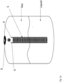
- Fig. 1 is a perspective view of a partial cut through of a composite pressure vessel where the sensor unit 5 is connected to a gas tight liner 4 of the composite pressure vessel.
- a composite pressure vessel for storing gas and/or liquified gas may comprise an inner gas tight liner 4, surrounded by a pressure resistant composite layer 2 of fibres and polymer.
- the liner 4 and the composite layer 2 comprise at least one common opening wherein a boss is arranged.
- the boss provides for attaching a valve 3 which is the inlet/outlet means for controlling the flow of fluid in and out of the pressure vessel.
- An outer casing 1 surrounds the composite layer 2 and provides protection against impact.
- the outer casing 1 may further provide a stand supporting a vertical arrangement of a cylindrical pressure vessel.
- the casing 1 may include other features such as handles for transport and adapting the bottom surface and the top surface to each other to allow stacking.
- the sensor unit 5 is placed on the side of the liner 4 of the composite pressure vessel.
- the sensor unit 5 is comprised of sensor electrodes 9 and a capacitive measuring unit 8.
- the sensor unit 5 has two reference points 6, 11.
- a first reference point 11 is positioned towards the lower end of the liner 4. This is a reference point for gas in liquid phase.
- the sensor unit 5 can be placed on the inside and outside of the liner 4, on the inside and on the outside of the composite material and on the inside and on the outside of the plastic cover.
- the sensor unit 5 For the sensor unit 5 to function properly the sensor unit 5 is glued to the side of the liner 4. It is important that there is proper contact between the sensor unit 5 and the vessel since the sensor unit 5 must stretch together with the pressure vessel to get accurate measurements.
- Fig. 2a is a drawing of an embodiment of the present invention illustrating the principle of the invention.
- the sensor unit 5 is capable of measuring absolute and relative change in the electrical field between at least two electrodes.
- the electrodes can be copper wires or traces or more suitable geometric shapes such as interdigitated finger pattern, semi-circular pattern or other patterns recognized suitable for those skilled in the art.
- the ideal pattern utilized is one with high degree of change in Electrical Field/Capacitance while being immune to external noise sources such as a second Electrical Field.
- the two sensor electrodes 9 form an Electrical Capacitor. This capacitor will be perturbed by the change in dielectric constant along the sensor electrodes 9 based on the amount of liquid gas present in the vessel.
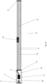
- Fig. 2b is a drawing of the sensor unit 5 and the parts it is composed of.
- the sensor unit 5 is in the form of a capacitive measuring unit 8 and sensor electrodes 9.
- This reference point 6 is measuring gas in gas phase.
- This reference point 6 is placed above the maximum fill level of the pressure vessel.
- At the opposite end of the sensor unit 5 there is another reference point 11 measuring gas in liquid phase. This reference point 11 measures the gas in liquid phase. If both reference points 6, 11 show the same reading the pressure vessel is either empty and needs refilling or it is overfilled.
- the sensor unit 5 has a Bluetooth transmitter, preferably a Bluetooth Low Energy (BLE) transmitter 7.
- BLE Bluetooth Low Energy
- This transmitter can transmit the information gathered by the sensors to a receiver.
- the receiver can be a mobile phone wherein the measured information can be showed in an app on the phone.
- the receiver can be an IoT gateway which transmits the information to an internet server where the information can be accessed by a user.
- the sensor unit 5 can also be comprised of a pressure sensor 10 and a temperature sensor 18. These sensors can contribute to the surveillance of the condition of the pressure vessel, but they are not necessary to measure the level of the gas in liquid phase.
- the pressure sensor can be made up of a double E capacitive sensor. This sensor expands and contract as the pressure in the tank either increases or decreases. The capacitance changes in relation to the expansion and contraction of the sensor. The close contact between the sensor and the pressure vessel has a positive effect on the accuracy of the sensor.
- the sensor is either attached to the pressure vessel using a strong adhesive or the sensor is embedded in either the liner, the composite material or the outer casing.
- the sensor unit 5 needs a power source.
- the power is supplied by an energy harvesting chip like the chip described in patent applications NO20170555 , NO 20181285 , NO20181286 and NO20181283 .
- This energy harvesting chip gathers energy from radio waves.
- the energy can be harvested by using solar panels attached to the pressure vessel. Both solutions have the benefit that they are maintenance free since they do not need to be recharged in the same way as a battery need.
- a battery can also be used as a power source.
- the sensor unit 5 can also be fitted with a memory unit 16. This allows the capacitive measuring unit 8 to store the measurements if the pressure vessel is not in contact with a Bluetooth receiver.
- Fig. 3 is an illustration of how the sensor unit 5 can communicate with the user of the system, communicating using BLE 7 to a mobile device 31.
- This solution allows the user to be able to access the information gathered by the sensor unit 5 and check the level of gas left in the pressure vessel.
- the connection can be initiated by the user or by the BLE 7 on the sensor unit 5. If it is accessed by the user, the latest stored information can be transmitted, or the sensor unit 5 can perform an on the spot measurement.
- the BLE 7 on the sensor unit 5 can initiate a transmission of information if the receiver is within transmitting range.
- the information is in the form of the level of gas in liquid phase in the pressure vessel.
- the app in the mobile device will be able to keep track of the gas level in the pressure vessel.
- the information can be shown to the user as either the level of gas in liquid phase or as the amount of gas left in the pressure vessel.
- the amount of gas left in the pressure vessel is calculated using the level of gas in liquid phase, the pressure in the pressure vessel and the volume of the pressure vessel.
- the amount of gas left in the pressure vessel can be displayed as a percentage of the maximum amount of gas allowed in the pressure vessel.
- Fig. 4 is an illustration of the sensor unit 5 communicating using BLE 7 to a gateway 32 capable of distributing the information via the internet to a remote destination.
- the BLE 7 on the pressure vessel can be connected to a receiver in the form of an Internet of Things (IoT) gateway.
- the gateway can transmit the measured information to an Internet database where the information can be accessed by a third party.
- IoT Internet of Things
- This solution allows the pressure vessel supplier with a possibility to keep track of the gas level in the pressure vessels. This allows them to change the gas for a customer without the customers involvement.
- several pressure vessels can be connected to one IoT gateway, wherein each of the pressure vessels has a sensor unit 5 attached in order to transmit their individual level via the IoT gateway to the service provider.
- the service provider can be informed if there are any unnatural leakage of gas from the pressure vessel.
- Fig. 5a is an illustration of the systems presented in fig. 3 where the flow of the information between the different parties of the systems is indicated.
- the sensor unit 5 attached to the composite pressure vessel sends the measured information to a mobile communication device 31 when it is within range of the communication unit 7 of the system.
- the measured information can be displayed in an app on the mobile communication device 31. If the displayed information reveals that the composite pressure vessel is empty, or close to empty the user can change the composite pressure vessel to a new filled composite pressure vessel.
- the measured information can be displayed on a digital display 33 situated on the pressure vessel.
- the digital display 33 can be in addition to the app om the mobile communication device 31. Alternatively, the digital display 33 can be instead of the app on the mobile communication device.
- Fig. 5b is an illustration of the systems presented in and fig. 4 where the flow of the information between the different parties of the systems is indicated.
- the communication device of the composite pressure vessel sends the measured information to an internet gateway 32.
- the internet gateway 32 sends the information to e.g. a site on the internet.
- the information can be accessed by a third party 34.
- the third party can be a supplier of composite pressure vessels. When the measured gas level of the composite pressure vessel shows that it is below a set threshold level the supplier can change the pressure vessel to a full one.
- the supplier can keep track of multiple pressure vessel placed in multiple places.
- each vessel can be fitted with a unique ID. This makes it possible to store historical data related to each individual composite pressure vessel.
- the location of all the pressure vessel that the supplier is responsible for can be displayed in a map in order to make it easier for the supplier to find out where an empty pressure vessel is located. Alternatively, it can be stored as information in a data sheet.
- each composite pressure vessel can be fitted with a satellite navigation unit that allows the supplier to keep track of the pressure vessel in real time. This makes it possible to keep track of the pressure vessel even if it has been moved.
- Fig. 6 is a detailed image of the embodiment presented in figure 4 wherein all the steps of the process and information flow is indicated. It is displayed that the composite pressure vessel (LPG Cylinder) 19 has an asset management platform 20. This platform 20 collects information about the individual pressure vessels 19. The collected data is sent to a Multicloud Management Platform (MCMP) 21.
- the MCMP 21 is comprised of a billing, rating and payment module 22 that keeps track of the billing, rating and payment related to each individual pressure vessel 19.
- the MCMP 21 can have a data management module 23.
- the data management module 23 stores and analyses the information sent from each pressure vessel 19. It can further keep track of the technical information related to each pressure vessel 19.
- the MCMP 21 can have one or more communication interfaces 24.
- the communication interfaces 24 can be a web interface, it can be a telecommunication interface (GSM networks) and additional networks like satellite navigation interface like GPS interface (Tracking device).
Landscapes
- Engineering & Computer Science (AREA)
- Physics & Mathematics (AREA)
- Power Engineering (AREA)
- Fluid Mechanics (AREA)
- General Physics & Mathematics (AREA)
- Electromagnetism (AREA)
- Thermal Sciences (AREA)
- Mechanical Engineering (AREA)
- General Engineering & Computer Science (AREA)
- Signal Processing (AREA)
- Filling Or Discharging Of Gas Storage Vessels (AREA)
Claims (13)
- System zum Messen des Gasstands in flüssiger Form in einem Verbunddruckbehälter, der elektrische Kapazität verwendet, um das Messen durchzuführen, wobei das System Folgendes umfasst:• eine kapazitive Messeinheit (8) zum Messen des Gasstands in flüssiger Form in dem Druckbehälter,• mindestens zwei Sensorelektroden (9), die mit der kapazitiven Messeinheit (8) verbunden sind,• eine Kommunikationseinheit (7) zum Kommunizieren der durch die kapazitive Messeinheit (8) gemessenen Informationen und• eine Leistungseinheit (17) zum Zuführen von Leistung zu mindestens einer von den mindestens zwei Elektroden, der kapazitiven Messeinheit (8) und der Kommunikationseinheit (7), dadurch gekennzeichnet, dassdie kapazitive Messeinheit (8) und die Sensorelektroden (9) in Form eines länglichen Streifens vorliegen, der so angeordnet ist, dass er sich im Wesentlichen über die vertikale Höhe einer Innenauskleidung des Verbunddruckbehälters erstreckt.
- System nach Anspruch 1, wobei die mindestens zwei Elektroden mindestens eine Übertragungselektrode und mindestens eine Empfangselektrode mit ineinandergreifenden Fingern umfassen.
- System nach Anspruch 2, wobei eine Sensoreinheit (5) einen Referenzpunkt (11), der sich nahe einem ersten Ende der Sensoreinheit (5) befindet, um an dem Verbunddruckbehälter auf einem Niveau angeordnet zu sein, auf dem das Gas stets in flüssiger Form vorliegt, und einen Referenzpunkt (6), der nahe einem zweiten Ende der Sensoreinheit (5) angeordnet ist, um an dem Verbunddruckbehälter auf einem Niveau angeordnet zu sein, auf dem das Gas stets in Gasform vorliegt, aufweist.
- System nach einem der Ansprüche 1-3, wobei die Leistungseinheit (17) ein Energieernter (17) ist.
- System nach einem der Ansprüche 1-4, wobei die Kommunikationseinheit (7) eine Nahbereichsfunkkommunikationseinheit (7) zum Kommunizieren von durch die kapazitive Messeinheit (8) gemessenen Informationen an einen Empfänger (31, 32, 33, 34) ist.
- System nach Anspruch 5, wobei die dem Benutzer angezeigten Informationen entweder die in dem Druckbehälter verbleibende Gasmenge oder die Gasmenge in flüssiger Form in dem Behälter sein können.
- System nach Anspruch 5, wobei der Empfänger eine Anzeige (33) ist, die sich an dem Verbunddruckbehälter befindet ist und die in dem Verbunddruckbehälter verbleibende Gasmenge anzeigt.
- System nach einem der Ansprüche 1-7, wobei das System ferner einen Temperatursensor (18), einen Drucksensor (10) und eine Speichereinheit (16) umfasst.
- Verfahren zum digitalen Überwachen des Gasstands in flüssiger Form in einem Verbunddruckbehälter, der aus mindestens einer gasdichten Innenauskleidung (4) im Inneren einer Schicht aus Verbundmaterial hergestellt ist, wobei das System eine Sensoreinheit (5) umfasst, die an der Auskleidung des Verbunddruckbehälters angebracht ist und die elektrische Kapazität verwendet, um die in dem Behälter vorhandene Gasmenge zu messen, wobei die Sensoreinheit (5) Folgendes umfasst: - eine kapazitive Messeinheit (8) zum Erfassen der Gasmenge in dem Druckbehälter, - mindestens zwei Sensorelektroden (9), die mit der kapazitiven Messeinheit (8) verbunden sind, wobei die kapazitive Messeinheit (8) und die Sensorelektroden (9) in Form eines länglichen Streifens vorliegen, der so angeordnet ist, dass er sich im Wesentlichen über die vertikale Höhe einer Innenauskleidung des Verbunddruckbehälters erstreckt, - eine Kommunikationseinheit (7) zum Kommunizieren der verbleibenden Gasmenge, die durch die kapazitive Messeinheit (8) erfasst wird, und eine Leistungseinheit (17) zum Zuführen von Leistung zu der kapazitiven Messeinheit (8), den Elektroden (9) und der Kommunikationseinheit (7);
wobei das Verfahren die folgenden Schritte umfasst:• Zuführen von Leistung von der Leistungseinheit (17) zu der kapazitiven Messeinheit (8), mindestens einer der Elektroden (9) und der Kommunikationseinheit (7);• Messen der in dem Verbunddruckbehälter vorhandenen Gasmenge mit der kapazitiven Messeinheit (8) anhand absoluter oder relativer Änderungen der elektrischen Kapazität,• Kommunizieren der gemessenen vorhandenen Gasmenge mit der Kommunikationseinheit (7) ani. eine Speichereinheit (16), welche die gemessene in dem Verbunddruckbehälter vorhandene Gasmenge in dem Speicher speichert, und/oderii. einen Empfänger (31, 32, 33, 34) und/oderiii. einen Benutzer (31, 33, 34), und/oderiv. Anzeigen der Informationen an einen Benutzer (31, 33). - Verfahren nach Anspruch 9, wobei die Leistungseinheit (17) ein Energieernter (17) ist, der Energie aus einem Umgebungsfunkfrequenzspektrum sammelt.
- Verfahren nach einem der Ansprüche 9-10, wobei das System einen Temperatursensor (18) zum Messen der Temperatur des Verbunddruckbehälters und einen Drucksensor (10) zum Messen des Drucks innerhalb des Druckbehälters umfasst und das Verfahren Berechnen der Gasmenge in dem Verbunddruckbehälter auf Grundlage der gemessenen Temperatur, des gemessenen Drucks und des gemessenen Gasstands in flüssiger Form in dem Verbunddruckbehälter umfasst.
- Verbunddruckbehälter, umfassend ein System zum Messen der verbleibenden Gasmenge nach einem der Ansprüche 1-8.
- Verbunddruckbehälter nach Anspruch 12, wobei der Verbunddruckbehälter ein zylindrischer Behälter ist, der für eine vertikale Ausrichtung der Zylinderachse angeordnet ist, wobei die Sensoreinheit (5) vertikal an der Innenauskleidung (4) angeordnet ist.
Applications Claiming Priority (2)
| Application Number | Priority Date | Filing Date | Title |
|---|---|---|---|
| EP20191894.3A EP3957898A1 (de) | 2020-08-20 | 2020-08-20 | System und verfahren zur digitalen überwachung eines druckbehälters |
| PCT/EP2021/073093 WO2022038249A1 (en) | 2020-08-20 | 2021-08-19 | System and method for digitally monitoring a pressure vessel |
Publications (3)
| Publication Number | Publication Date |
|---|---|
| EP4200554A1 EP4200554A1 (de) | 2023-06-28 |
| EP4200554C0 EP4200554C0 (de) | 2024-12-18 |
| EP4200554B1 true EP4200554B1 (de) | 2024-12-18 |
Family
ID=72178407
Family Applications (2)
| Application Number | Title | Priority Date | Filing Date |
|---|---|---|---|
| EP20191894.3A Withdrawn EP3957898A1 (de) | 2020-08-20 | 2020-08-20 | System und verfahren zur digitalen überwachung eines druckbehälters |
| EP21765645.3A Active EP4200554B1 (de) | 2020-08-20 | 2021-08-19 | System und verfahren zur digitalen überwachung eines druckbehälters |
Family Applications Before (1)
| Application Number | Title | Priority Date | Filing Date |
|---|---|---|---|
| EP20191894.3A Withdrawn EP3957898A1 (de) | 2020-08-20 | 2020-08-20 | System und verfahren zur digitalen überwachung eines druckbehälters |
Country Status (3)
| Country | Link |
|---|---|
| US (1) | US20240011604A1 (de) |
| EP (2) | EP3957898A1 (de) |
| WO (1) | WO2022038249A1 (de) |
Families Citing this family (4)
| Publication number | Priority date | Publication date | Assignee | Title |
|---|---|---|---|---|
| EP3957899A1 (de) * | 2020-08-20 | 2022-02-23 | Hexagon Ragasco AS | Digitale überwachung eines zusammengesetzten druckbehälters |
| DE102022122949A1 (de) * | 2022-09-09 | 2024-03-14 | SCHäFER WERKE GMBH | Verfahren zur indirekten Messung des Füllstandes in einem Gefäß |
| USD1076697S1 (en) * | 2023-02-10 | 2025-05-27 | Reign RMC, LLC | Visual indicator for above-ground storage tank |
| USD1074483S1 (en) * | 2023-02-10 | 2025-05-13 | Reign RMC, LLC | Visual indicator |
Citations (15)
| Publication number | Priority date | Publication date | Assignee | Title |
|---|---|---|---|---|
| CA2113774A1 (en) * | 1994-01-19 | 1995-07-20 | Harold L. Gier | Loading, storage and delivery apparatus and method for fluid at cryogenic temperature |
| US5582016A (en) * | 1992-05-07 | 1996-12-10 | Aerospace Design & Development, Inc. | Conditioning and loading apparatus and method for gas storage at cryogenic temperature and supercritical pressure |
| US6712276B1 (en) * | 1999-01-29 | 2004-03-30 | International Business Machines Corporation | Method and apparatus for automated measurement of properties of perishable consumer products |
| US20090301190A1 (en) * | 2008-06-09 | 2009-12-10 | Rochester Gauges, Inc. | Capacitive sensor assembly for determining relative position |
| US20130166175A1 (en) * | 2011-12-27 | 2013-06-27 | Aisan Kogyo Kabushiki Kaisha | Sensor and control device |
| US20130276533A1 (en) * | 2011-01-10 | 2013-10-24 | Strauss Water Ltd. | Device for measuring fluid level in a container |
| JP5690641B2 (ja) * | 2011-04-20 | 2015-03-25 | 矢崎総業株式会社 | 液面レベルセンサ及びそれを有する液面レベル検出装置 |
| US9103920B2 (en) * | 2012-06-01 | 2015-08-11 | Landauer, Inc. | Energy harvester for wireless, motion and position-sensing, integrating radiation sensor for occupational and environmental dosimetry |
| WO2015145468A1 (en) * | 2014-03-28 | 2015-10-01 | Faber Industrie S.P.A. | Composite-material pressure vessel and system and method for controlling the vessel |
| CN105091979A (zh) * | 2015-09-21 | 2015-11-25 | 中国石油大学(华东) | 一种利用三角形电容式传感器进行液位测量的方法 |
| WO2016112037A1 (en) * | 2015-01-05 | 2016-07-14 | Resocator, Inc. | Global resource locator |
| CN108471811A (zh) * | 2016-02-12 | 2018-08-31 | 菲利普莫里斯生产公司 | 具有电极的气溶胶生成系统 |
| US10119657B2 (en) * | 2012-06-19 | 2018-11-06 | Shailendra Suman | Propane tank continuous monitoring system |
| US20190242527A1 (en) * | 2018-02-08 | 2019-08-08 | David Milner | Method and device for withdrawing vapor and measuring liquid level in a cylinder containing liquefied gas |
| CN110631655A (zh) * | 2019-10-11 | 2019-12-31 | 江苏智冷物联技术有限公司 | 一种一体化无线远传液位计 |
Family Cites Families (18)
| Publication number | Priority date | Publication date | Assignee | Title |
|---|---|---|---|---|
| FR2680767A1 (fr) * | 1991-08-30 | 1993-03-05 | Air Liquide | Conteneur comportant des moyens detecteurs de niveau de liquide dans le conteneur. |
| US5726908A (en) * | 1995-03-20 | 1998-03-10 | Figgie International Inc. | Liquid quantity sensor and method |
| CA2212244C (en) * | 1995-12-04 | 2007-05-29 | Toray Industries, Inc. | Pressure vessel and process for producing the same |
| US6016697A (en) * | 1997-09-09 | 2000-01-25 | American Magnetics, Inc. | Capacitive level sensor and control system |
| WO2004003488A1 (en) * | 2002-06-28 | 2004-01-08 | Genieo Solutions Design | Apparatus for external monitoring of the fluid level in a container |
| US7086593B2 (en) * | 2003-04-30 | 2006-08-08 | The United States Of America As Represented By The Administrator Of The National Aeronautics And Space Administration | Magnetic field response measurement acquisition system |
| FR2929704B1 (fr) * | 2008-04-04 | 2010-05-14 | Univ Joseph Fourier | Detecteur capacitif, procede de fabrication d'un detecteur capacitif et dispositif de mesure l'integrant |
| US8661875B2 (en) * | 2012-05-07 | 2014-03-04 | Caterpillar Inc. | System and method to detect accumulator loss of precharge |
| US10066979B2 (en) * | 2014-12-03 | 2018-09-04 | Rochester Gauges, Inc. | Sealed head construction for liquid level transducers |
| US10158401B2 (en) * | 2015-02-27 | 2018-12-18 | Ricoh Co., Ltd. | Intelligent network sensor system |
| US9874470B2 (en) | 2016-01-12 | 2018-01-23 | Tank Vision, Inc. | Fuel tank level monitoring system |
| EP4417944A1 (de) * | 2016-10-21 | 2024-08-21 | Silicon Controls Pty Ltd | Telemetrische armatur und verfahren zur telemetrischen messung |
| NO20170555A1 (en) | 2017-04-04 | 2018-10-05 | Cura8 As | Sensor system and method for continuous and wireless monitoring and analysis of temperature in organisms |
| US10684157B2 (en) * | 2017-04-20 | 2020-06-16 | Rochester Gauges, Inc. | Liquid level gauge with integral electronic display |
| US11214140B2 (en) * | 2017-06-07 | 2022-01-04 | Stratosphere, S.A. | Fuel tank with integrated level sensors, in particular for aerial vehicles |
| NO20181286A1 (en) | 2018-10-04 | 2020-04-06 | ONiO AS | Sensor system and method for continuous and wireless monitoring and analysis of respiratory sounds, heart rate and core temperature in organism |
| NO20181285A1 (en) | 2018-10-04 | 2020-04-06 | ONiO AS | Sensor system with notification function and method for continuous and wireless monitoring and analysis of temperature in organisms |
| NO20181283A1 (en) | 2018-10-04 | 2020-04-06 | ONiO AS | Sensor system and method for continuous and wireless monitoring and analysis of heart sounds, circulatory effects and core temperature in organisms |
-
2020
- 2020-08-20 EP EP20191894.3A patent/EP3957898A1/de not_active Withdrawn
-
2021
- 2021-08-19 US US18/021,329 patent/US20240011604A1/en active Pending
- 2021-08-19 WO PCT/EP2021/073093 patent/WO2022038249A1/en not_active Ceased
- 2021-08-19 EP EP21765645.3A patent/EP4200554B1/de active Active
Patent Citations (16)
| Publication number | Priority date | Publication date | Assignee | Title |
|---|---|---|---|---|
| US5582016A (en) * | 1992-05-07 | 1996-12-10 | Aerospace Design & Development, Inc. | Conditioning and loading apparatus and method for gas storage at cryogenic temperature and supercritical pressure |
| CA2113774A1 (en) * | 1994-01-19 | 1995-07-20 | Harold L. Gier | Loading, storage and delivery apparatus and method for fluid at cryogenic temperature |
| US6712276B1 (en) * | 1999-01-29 | 2004-03-30 | International Business Machines Corporation | Method and apparatus for automated measurement of properties of perishable consumer products |
| US20090301190A1 (en) * | 2008-06-09 | 2009-12-10 | Rochester Gauges, Inc. | Capacitive sensor assembly for determining relative position |
| US7997132B2 (en) * | 2008-06-09 | 2011-08-16 | Rochester Gauges, Inc. | Capacitive sensor assembly for determining relative position |
| US20130276533A1 (en) * | 2011-01-10 | 2013-10-24 | Strauss Water Ltd. | Device for measuring fluid level in a container |
| JP5690641B2 (ja) * | 2011-04-20 | 2015-03-25 | 矢崎総業株式会社 | 液面レベルセンサ及びそれを有する液面レベル検出装置 |
| US20130166175A1 (en) * | 2011-12-27 | 2013-06-27 | Aisan Kogyo Kabushiki Kaisha | Sensor and control device |
| US9103920B2 (en) * | 2012-06-01 | 2015-08-11 | Landauer, Inc. | Energy harvester for wireless, motion and position-sensing, integrating radiation sensor for occupational and environmental dosimetry |
| US10119657B2 (en) * | 2012-06-19 | 2018-11-06 | Shailendra Suman | Propane tank continuous monitoring system |
| WO2015145468A1 (en) * | 2014-03-28 | 2015-10-01 | Faber Industrie S.P.A. | Composite-material pressure vessel and system and method for controlling the vessel |
| WO2016112037A1 (en) * | 2015-01-05 | 2016-07-14 | Resocator, Inc. | Global resource locator |
| CN105091979A (zh) * | 2015-09-21 | 2015-11-25 | 中国石油大学(华东) | 一种利用三角形电容式传感器进行液位测量的方法 |
| CN108471811A (zh) * | 2016-02-12 | 2018-08-31 | 菲利普莫里斯生产公司 | 具有电极的气溶胶生成系统 |
| US20190242527A1 (en) * | 2018-02-08 | 2019-08-08 | David Milner | Method and device for withdrawing vapor and measuring liquid level in a cylinder containing liquefied gas |
| CN110631655A (zh) * | 2019-10-11 | 2019-12-31 | 江苏智冷物联技术有限公司 | 一种一体化无线远传液位计 |
Also Published As
| Publication number | Publication date |
|---|---|
| EP3957898A1 (de) | 2022-02-23 |
| EP4200554C0 (de) | 2024-12-18 |
| US20240011604A1 (en) | 2024-01-11 |
| WO2022038249A1 (en) | 2022-02-24 |
| EP4200554A1 (de) | 2023-06-28 |
Similar Documents
| Publication | Publication Date | Title |
|---|---|---|
| EP4200554B1 (de) | System und verfahren zur digitalen überwachung eines druckbehälters | |
| EP4200555B1 (de) | Digitale überwachung eines zusammengesetzten druckbehälters | |
| US20250102119A1 (en) | Systems and Methods for Improved Asset Monitoring via Orientation Measurement | |
| US20230385589A1 (en) | A method and a system for monitoring a quantity related to an asset | |
| US11887052B2 (en) | System and method for determining volume of fluid in a tank | |
| US20110000295A1 (en) | Remote level gauge adapted for liquid fuel tank | |
| US20230366716A1 (en) | Telemetric fitting and method of telemetric measurement | |
| EP3953636B1 (de) | Verfahren zur überwachung von flüssiggas in einem kryogenen flüssiggastank und kryotank | |
| AU2018100195A4 (en) | System, method, and apparatus for monitoring a plurality of tanks | |
| CN108896081A (zh) | 测量仪器 | |
| US20250164076A1 (en) | Smart composite pressure vessel | |
| EP2330393B1 (de) | In-line Messeinheit für Kraftstoffeigenschaften | |
| CN209370852U (zh) | 一种埋地管道外防腐层破损检测装置 | |
| CN111579575A (zh) | 一种用于lng储罐蒸发率测试的在线监测系统 | |
| EP3819603A1 (de) | Kraftstoffabgabeumgebung mit drahtloser sensoranordnung | |
| IT202300003441A1 (it) | Pozzetto migliorato | |
| IT202300003432A1 (it) | Pozzetto migliorato | |
| KR100516580B1 (ko) | 초음파식 연속용량 계량장치 |
Legal Events
| Date | Code | Title | Description |
|---|---|---|---|
| STAA | Information on the status of an ep patent application or granted ep patent |
Free format text: STATUS: UNKNOWN |
|
| STAA | Information on the status of an ep patent application or granted ep patent |
Free format text: STATUS: THE INTERNATIONAL PUBLICATION HAS BEEN MADE |
|
| PUAI | Public reference made under article 153(3) epc to a published international application that has entered the european phase |
Free format text: ORIGINAL CODE: 0009012 |
|
| STAA | Information on the status of an ep patent application or granted ep patent |
Free format text: STATUS: REQUEST FOR EXAMINATION WAS MADE |
|
| 17P | Request for examination filed |
Effective date: 20230313 |
|
| AK | Designated contracting states |
Kind code of ref document: A1 Designated state(s): AL AT BE BG CH CY CZ DE DK EE ES FI FR GB GR HR HU IE IS IT LI LT LU LV MC MK MT NL NO PL PT RO RS SE SI SK SM TR |
|
| DAV | Request for validation of the european patent (deleted) | ||
| DAX | Request for extension of the european patent (deleted) | ||
| REG | Reference to a national code |
Ref country code: DE Ref legal event code: R079 Ipc: G01F0023263000 Ref country code: DE Ref legal event code: R079 Ref document number: 602021023608 Country of ref document: DE Free format text: PREVIOUS MAIN CLASS: F17C0013000000 Ipc: G01F0023263000 |
|
| GRAP | Despatch of communication of intention to grant a patent |
Free format text: ORIGINAL CODE: EPIDOSNIGR1 |
|
| STAA | Information on the status of an ep patent application or granted ep patent |
Free format text: STATUS: GRANT OF PATENT IS INTENDED |
|
| RIC1 | Information provided on ipc code assigned before grant |
Ipc: F17C 13/02 20060101ALI20240229BHEP Ipc: G01F 23/80 20220101ALI20240229BHEP Ipc: G01F 23/263 20220101AFI20240229BHEP |
|
| INTG | Intention to grant announced |
Effective date: 20240322 |
|
| GRAJ | Information related to disapproval of communication of intention to grant by the applicant or resumption of examination proceedings by the epo deleted |
Free format text: ORIGINAL CODE: EPIDOSDIGR1 |
|
| STAA | Information on the status of an ep patent application or granted ep patent |
Free format text: STATUS: REQUEST FOR EXAMINATION WAS MADE |
|
| INTC | Intention to grant announced (deleted) | ||
| GRAP | Despatch of communication of intention to grant a patent |
Free format text: ORIGINAL CODE: EPIDOSNIGR1 |
|
| STAA | Information on the status of an ep patent application or granted ep patent |
Free format text: STATUS: GRANT OF PATENT IS INTENDED |
|
| INTG | Intention to grant announced |
Effective date: 20240812 |
|
| GRAS | Grant fee paid |
Free format text: ORIGINAL CODE: EPIDOSNIGR3 |
|
| GRAA | (expected) grant |
Free format text: ORIGINAL CODE: 0009210 |
|
| STAA | Information on the status of an ep patent application or granted ep patent |
Free format text: STATUS: THE PATENT HAS BEEN GRANTED |
|
| AK | Designated contracting states |
Kind code of ref document: B1 Designated state(s): AL AT BE BG CH CY CZ DE DK EE ES FI FR GB GR HR HU IE IS IT LI LT LU LV MC MK MT NL NO PL PT RO RS SE SI SK SM TR |
|
| REG | Reference to a national code |
Ref country code: CH Ref legal event code: EP |
|
| REG | Reference to a national code |
Ref country code: DE Ref legal event code: R096 Ref document number: 602021023608 Country of ref document: DE |
|
| REG | Reference to a national code |
Ref country code: IE Ref legal event code: FG4D |
|
| U01 | Request for unitary effect filed |
Effective date: 20241218 |
|
| U07 | Unitary effect registered |
Designated state(s): AT BE BG DE DK EE FI FR IT LT LU LV MT NL PT RO SE SI Effective date: 20250102 |
|
| RAP4 | Party data changed (patent owner data changed or rights of a patent transferred) |
Owner name: RAGASCO AS |
|
| U1H | Name or address of the proprietor changed after the registration of the unitary effect |
Owner name: RAGASCO AS; NO |
|
| PG25 | Lapsed in a contracting state [announced via postgrant information from national office to epo] |
Ref country code: HR Free format text: LAPSE BECAUSE OF FAILURE TO SUBMIT A TRANSLATION OF THE DESCRIPTION OR TO PAY THE FEE WITHIN THE PRESCRIBED TIME-LIMIT Effective date: 20241218 |
|
| PG25 | Lapsed in a contracting state [announced via postgrant information from national office to epo] |
Ref country code: GR Free format text: LAPSE BECAUSE OF FAILURE TO SUBMIT A TRANSLATION OF THE DESCRIPTION OR TO PAY THE FEE WITHIN THE PRESCRIBED TIME-LIMIT Effective date: 20250319 |
|
| PG25 | Lapsed in a contracting state [announced via postgrant information from national office to epo] |
Ref country code: RS Free format text: LAPSE BECAUSE OF FAILURE TO SUBMIT A TRANSLATION OF THE DESCRIPTION OR TO PAY THE FEE WITHIN THE PRESCRIBED TIME-LIMIT Effective date: 20250318 |
|
| PG25 | Lapsed in a contracting state [announced via postgrant information from national office to epo] |
Ref country code: SM Free format text: LAPSE BECAUSE OF FAILURE TO SUBMIT A TRANSLATION OF THE DESCRIPTION OR TO PAY THE FEE WITHIN THE PRESCRIBED TIME-LIMIT Effective date: 20241218 |
|
| PG25 | Lapsed in a contracting state [announced via postgrant information from national office to epo] |
Ref country code: PL Free format text: LAPSE BECAUSE OF FAILURE TO SUBMIT A TRANSLATION OF THE DESCRIPTION OR TO PAY THE FEE WITHIN THE PRESCRIBED TIME-LIMIT Effective date: 20241218 |
|
| PG25 | Lapsed in a contracting state [announced via postgrant information from national office to epo] |
Ref country code: ES Free format text: LAPSE BECAUSE OF FAILURE TO SUBMIT A TRANSLATION OF THE DESCRIPTION OR TO PAY THE FEE WITHIN THE PRESCRIBED TIME-LIMIT Effective date: 20241218 |
|
| PG25 | Lapsed in a contracting state [announced via postgrant information from national office to epo] |
Ref country code: IS Free format text: LAPSE BECAUSE OF FAILURE TO SUBMIT A TRANSLATION OF THE DESCRIPTION OR TO PAY THE FEE WITHIN THE PRESCRIBED TIME-LIMIT Effective date: 20250418 |
|
| PGFP | Annual fee paid to national office [announced via postgrant information from national office to epo] |
Ref country code: NO Payment date: 20250606 Year of fee payment: 5 |
|
| PG25 | Lapsed in a contracting state [announced via postgrant information from national office to epo] |
Ref country code: SK Free format text: LAPSE BECAUSE OF FAILURE TO SUBMIT A TRANSLATION OF THE DESCRIPTION OR TO PAY THE FEE WITHIN THE PRESCRIBED TIME-LIMIT Effective date: 20241218 |
|
| U20 | Renewal fee for the european patent with unitary effect paid |
Year of fee payment: 5 Effective date: 20250708 |
|
| PLBE | No opposition filed within time limit |
Free format text: ORIGINAL CODE: 0009261 |
|
| STAA | Information on the status of an ep patent application or granted ep patent |
Free format text: STATUS: NO OPPOSITION FILED WITHIN TIME LIMIT |
|
| 26N | No opposition filed |
Effective date: 20250919 |