EP4199192A2 - Plaque de refroidissement d'un module de batterie d'une batterie de traction d'un véhicule automobile, son procédé de fabrication et module de batterie - Google Patents
Plaque de refroidissement d'un module de batterie d'une batterie de traction d'un véhicule automobile, son procédé de fabrication et module de batterie Download PDFInfo
- Publication number
- EP4199192A2 EP4199192A2 EP22209353.6A EP22209353A EP4199192A2 EP 4199192 A2 EP4199192 A2 EP 4199192A2 EP 22209353 A EP22209353 A EP 22209353A EP 4199192 A2 EP4199192 A2 EP 4199192A2
- Authority
- EP
- European Patent Office
- Prior art keywords
- coolant
- plate
- cooling
- battery
- cooling plate
- Prior art date
- Legal status (The legal status is an assumption and is not a legal conclusion. Google has not performed a legal analysis and makes no representation as to the accuracy of the status listed.)
- Pending
Links
- 238000001816 cooling Methods 0.000 title claims abstract description 140
- 238000004519 manufacturing process Methods 0.000 title claims description 8
- 239000002826 coolant Substances 0.000 claims abstract description 121
- 230000007704 transition Effects 0.000 claims description 20
- 239000002184 metal Substances 0.000 claims description 7
- 230000000712 assembly Effects 0.000 claims description 6
- 238000000429 assembly Methods 0.000 claims description 6
- 238000005476 soldering Methods 0.000 claims description 4
- 239000012809 cooling fluid Substances 0.000 description 21
- XLYOFNOQVPJJNP-UHFFFAOYSA-N water Substances O XLYOFNOQVPJJNP-UHFFFAOYSA-N 0.000 description 5
- 238000000034 method Methods 0.000 description 2
- 238000010146 3D printing Methods 0.000 description 1
- 101100004280 Caenorhabditis elegans best-2 gene Proteins 0.000 description 1
- 238000006243 chemical reaction Methods 0.000 description 1
- 230000001419 dependent effect Effects 0.000 description 1
- 238000011161 development Methods 0.000 description 1
- 230000018109 developmental process Effects 0.000 description 1
- 239000012530 fluid Substances 0.000 description 1
- 238000010438 heat treatment Methods 0.000 description 1
- 238000013021 overheating Methods 0.000 description 1
- 238000004080 punching Methods 0.000 description 1
- 238000003466 welding Methods 0.000 description 1
Images


Classifications
-
- H—ELECTRICITY
- H01—ELECTRIC ELEMENTS
- H01M—PROCESSES OR MEANS, e.g. BATTERIES, FOR THE DIRECT CONVERSION OF CHEMICAL ENERGY INTO ELECTRICAL ENERGY
- H01M10/00—Secondary cells; Manufacture thereof
- H01M10/60—Heating or cooling; Temperature control
- H01M10/65—Means for temperature control structurally associated with the cells
- H01M10/655—Solid structures for heat exchange or heat conduction
- H01M10/6556—Solid parts with flow channel passages or pipes for heat exchange
-
- H—ELECTRICITY
- H01—ELECTRIC ELEMENTS
- H01M—PROCESSES OR MEANS, e.g. BATTERIES, FOR THE DIRECT CONVERSION OF CHEMICAL ENERGY INTO ELECTRICAL ENERGY
- H01M10/00—Secondary cells; Manufacture thereof
- H01M10/60—Heating or cooling; Temperature control
- H01M10/65—Means for temperature control structurally associated with the cells
- H01M10/655—Solid structures for heat exchange or heat conduction
- H01M10/6554—Rods or plates
- H01M10/6555—Rods or plates arranged between the cells
-
- B—PERFORMING OPERATIONS; TRANSPORTING
- B21—MECHANICAL METAL-WORKING WITHOUT ESSENTIALLY REMOVING MATERIAL; PUNCHING METAL
- B21C—MANUFACTURE OF METAL SHEETS, WIRE, RODS, TUBES OR PROFILES, OTHERWISE THAN BY ROLLING; AUXILIARY OPERATIONS USED IN CONNECTION WITH METAL-WORKING WITHOUT ESSENTIALLY REMOVING MATERIAL
- B21C37/00—Manufacture of metal sheets, bars, wire, tubes or like semi-manufactured products, not otherwise provided for; Manufacture of tubes of special shape
- B21C37/02—Manufacture of metal sheets, bars, wire, tubes or like semi-manufactured products, not otherwise provided for; Manufacture of tubes of special shape of sheets
-
- B—PERFORMING OPERATIONS; TRANSPORTING
- B60—VEHICLES IN GENERAL
- B60L—PROPULSION OF ELECTRICALLY-PROPELLED VEHICLES; SUPPLYING ELECTRIC POWER FOR AUXILIARY EQUIPMENT OF ELECTRICALLY-PROPELLED VEHICLES; ELECTRODYNAMIC BRAKE SYSTEMS FOR VEHICLES IN GENERAL; MAGNETIC SUSPENSION OR LEVITATION FOR VEHICLES; MONITORING OPERATING VARIABLES OF ELECTRICALLY-PROPELLED VEHICLES; ELECTRIC SAFETY DEVICES FOR ELECTRICALLY-PROPELLED VEHICLES
- B60L50/00—Electric propulsion with power supplied within the vehicle
- B60L50/50—Electric propulsion with power supplied within the vehicle using propulsion power supplied by batteries or fuel cells
- B60L50/60—Electric propulsion with power supplied within the vehicle using propulsion power supplied by batteries or fuel cells using power supplied by batteries
- B60L50/64—Constructional details of batteries specially adapted for electric vehicles
-
- H—ELECTRICITY
- H01—ELECTRIC ELEMENTS
- H01M—PROCESSES OR MEANS, e.g. BATTERIES, FOR THE DIRECT CONVERSION OF CHEMICAL ENERGY INTO ELECTRICAL ENERGY
- H01M10/00—Secondary cells; Manufacture thereof
- H01M10/60—Heating or cooling; Temperature control
- H01M10/61—Types of temperature control
- H01M10/613—Cooling or keeping cold
-
- H—ELECTRICITY
- H01—ELECTRIC ELEMENTS
- H01M—PROCESSES OR MEANS, e.g. BATTERIES, FOR THE DIRECT CONVERSION OF CHEMICAL ENERGY INTO ELECTRICAL ENERGY
- H01M10/00—Secondary cells; Manufacture thereof
- H01M10/60—Heating or cooling; Temperature control
- H01M10/62—Heating or cooling; Temperature control specially adapted for specific applications
- H01M10/625—Vehicles
-
- H—ELECTRICITY
- H01—ELECTRIC ELEMENTS
- H01M—PROCESSES OR MEANS, e.g. BATTERIES, FOR THE DIRECT CONVERSION OF CHEMICAL ENERGY INTO ELECTRICAL ENERGY
- H01M10/00—Secondary cells; Manufacture thereof
- H01M10/60—Heating or cooling; Temperature control
- H01M10/64—Heating or cooling; Temperature control characterised by the shape of the cells
- H01M10/643—Cylindrical cells
-
- H—ELECTRICITY
- H01—ELECTRIC ELEMENTS
- H01M—PROCESSES OR MEANS, e.g. BATTERIES, FOR THE DIRECT CONVERSION OF CHEMICAL ENERGY INTO ELECTRICAL ENERGY
- H01M10/00—Secondary cells; Manufacture thereof
- H01M10/60—Heating or cooling; Temperature control
- H01M10/65—Means for temperature control structurally associated with the cells
- H01M10/655—Solid structures for heat exchange or heat conduction
- H01M10/6556—Solid parts with flow channel passages or pipes for heat exchange
- H01M10/6557—Solid parts with flow channel passages or pipes for heat exchange arranged between the cells
-
- H—ELECTRICITY
- H01—ELECTRIC ELEMENTS
- H01M—PROCESSES OR MEANS, e.g. BATTERIES, FOR THE DIRECT CONVERSION OF CHEMICAL ENERGY INTO ELECTRICAL ENERGY
- H01M10/00—Secondary cells; Manufacture thereof
- H01M10/60—Heating or cooling; Temperature control
- H01M10/65—Means for temperature control structurally associated with the cells
- H01M10/656—Means for temperature control structurally associated with the cells characterised by the type of heat-exchange fluid
- H01M10/6567—Liquids
- H01M10/6568—Liquids characterised by flow circuits, e.g. loops, located externally to the cells or cell casings
-
- H—ELECTRICITY
- H01—ELECTRIC ELEMENTS
- H01M—PROCESSES OR MEANS, e.g. BATTERIES, FOR THE DIRECT CONVERSION OF CHEMICAL ENERGY INTO ELECTRICAL ENERGY
- H01M2220/00—Batteries for particular applications
- H01M2220/20—Batteries in motive systems, e.g. vehicle, ship, plane
-
- H—ELECTRICITY
- H01—ELECTRIC ELEMENTS
- H01M—PROCESSES OR MEANS, e.g. BATTERIES, FOR THE DIRECT CONVERSION OF CHEMICAL ENERGY INTO ELECTRICAL ENERGY
- H01M50/00—Constructional details or processes of manufacture of the non-active parts of electrochemical cells other than fuel cells, e.g. hybrid cells
- H01M50/20—Mountings; Secondary casings or frames; Racks, modules or packs; Suspension devices; Shock absorbers; Transport or carrying devices; Holders
- H01M50/204—Racks, modules or packs for multiple batteries or multiple cells
- H01M50/207—Racks, modules or packs for multiple batteries or multiple cells characterised by their shape
- H01M50/213—Racks, modules or packs for multiple batteries or multiple cells characterised by their shape adapted for cells having curved cross-section, e.g. round or elliptic
-
- Y—GENERAL TAGGING OF NEW TECHNOLOGICAL DEVELOPMENTS; GENERAL TAGGING OF CROSS-SECTIONAL TECHNOLOGIES SPANNING OVER SEVERAL SECTIONS OF THE IPC; TECHNICAL SUBJECTS COVERED BY FORMER USPC CROSS-REFERENCE ART COLLECTIONS [XRACs] AND DIGESTS
- Y02—TECHNOLOGIES OR APPLICATIONS FOR MITIGATION OR ADAPTATION AGAINST CLIMATE CHANGE
- Y02E—REDUCTION OF GREENHOUSE GAS [GHG] EMISSIONS, RELATED TO ENERGY GENERATION, TRANSMISSION OR DISTRIBUTION
- Y02E60/00—Enabling technologies; Technologies with a potential or indirect contribution to GHG emissions mitigation
- Y02E60/10—Energy storage using batteries
Definitions
- the invention relates to a cooling plate of a battery module of a traction battery of a motor vehicle. Furthermore, the invention relates to a method for producing such a cooling plate and a battery module.
- traction batteries are installed, which are used to store electrical energy in order to provide the same to an electrical machine.
- Traction batteries have several battery modules that are electrically interconnected. Each battery module has several battery cells, which are also electrically interconnected. During operation, the battery cells are subject to heating, for example as a result of chemical reactions within the battery cells. In order to avoid damage to the battery modules and thus to the traction battery as a result of overheating of the battery cells, heat must be dissipated from the traction battery by cooling the battery cells. It is already known to cool the battery cells of a traction battery. For this purpose, a battery module of a traction battery has a device for cooling the battery cells.
- the water cooling plate for a battery pack.
- the water cooling plate has a first plate, a second plate, and a channel structure sandwiched between the first plate and the second plate. Furthermore, the water cooling plate has a separate connector that forms a water inlet and a water outlet.
- the two plates as well as the channel structure are formed by stamping, these assemblies being joined together by welding.
- CN 207 967 246 U discloses a cooling device for an automotive battery.
- the cooling device is composed of plates, with a separate inlet and a separate outlet for coolant being formed on an upper plate.
- the cooling plate serves to cool several battery modules.
- the object of the invention is to create a cooling plate for a battery module of a traction battery in a motor vehicle, a method for producing such a cooling plate for a traction battery and a battery module with such cooling plates.
- the cooling plate according to the invention has a first plate body and a second plate body connected to the first plate body.
- the cooling plate according to the invention has a coolant inlet defined or formed by the first plate body and the second plate body on a first side of the cooling plate.
- the cooling plate according to the invention also has a coolant outlet defined or formed by the first plate body and the second plate body on a second side of the cooling plate.
- the cooling plate according to the invention also has coolant channels defined or formed by the first plate body and the second plate body, with a first coolant channel, which is coupled to the coolant inlet, extending from the first side in the direction of the second side, with a second coolant channel coupled to the first coolant channel extending from the second side toward the first side, and a third coolant channel coupled to the second coolant channel and the coolant drain extending from the first side toward the second side extends.
- the cooling plate according to the invention is composed of the first plate body and the second plate body.
- the two plate bodies define or form both the coolant inlet and the coolant outlet as well as the coolant channels extending between the coolant inlet and the coolant outlet.
- the cooling plate according to the invention is therefore formed by only two assemblies, namely by the two plate bodies.
- the cooling plate has a simple structure and can be easily manufactured.
- the coolant inlet, the coolant channels and the coolant outlet are preferably delimited in sections by sections of the plate bodies which abut and are connected to one another.
- the abutting and interconnected sections of the plate bodies are formed by elevations of the plate bodies, depressions of the plate bodies extending between the elevations of the plate bodies, which are spaced apart and enclose the coolant inlet, the coolant channels and the coolant outlet. This allows a particularly simple production of the cooling plate.
- the coolant inlet, the coolant channels and the coolant outlet are preferably integral parts of the plate body.
- the number of assemblies in the cooling plate is reduced to just two, which means that the cooling plate can be manufactured particularly easily.
- the plate bodies are formed from stamped metal sheets that are soldered together. This is particularly preferred in order to easily manufacture the cooling plate according to the invention.
- Round or oval sections of the plate bodies preferably adjoin and are connected to one another in a transition area between the coolant inlet and the first coolant channel and/or in a transition area between the third coolant channel and the coolant outlet.
- the round or oval sections favor an advantageous flow guidance in the respective transition area, on the other hand, they give the cooling plate a high degree of stability, even at high flow pressures.
- bent or curved, in particular sickle-shaped, sections of the plate bodies preferably adjoin and are connected to one another.
- the bent or curved, in particular sickle-shaped, sections also promote the flow guidance of the cooling fluid and give the cooling plate a high level of stability even at high flow pressures.
- the battery module according to the invention is defined in claim 9.
- the method according to the invention for producing a cooling plate of a battery module of a traction battery is defined in claim 10.
- FIG. 1 shows a perspective view of a preferred embodiment of a device 10 for cooling battery cells 35 of a battery module of a traction battery of a motor vehicle. In 1 only two battery cells 35 are shown.
- the arrangement of 1 can be accommodated in a module housing (not shown) of the battery module.
- the battery cells 35 are arranged in two battery cell planes 11, 12 arranged one above the other.
- a plurality of battery cells 35 are arranged in a first or upper battery cell level 11 and in a second or lower battery cell level 12 .
- in 1 only two battery cells 35 are shown, both of which are arranged in the upper battery cell level 11 .
- the device 10 for cooling the battery cells 35 has a first cooling plate 13 which is arranged between the first battery cell level 11 and the second battery cell level 12 and which, via its outer sides, is in thermal contact with the battery cells 35 of the first battery cell level 11 and in thermal contact with the battery cells 35 of the second battery cell level 12 is available.
- the first cooling plate 13 is in thermal contact with an underside of the battery cells 35 of the first battery cell level 11 via a first outer side and with an upper side of the battery cells 35 of the second battery cell level 12 via a second outer side.
- Electrical contacts (not shown) of the battery cells 35 are formed on the upper side of the battery cells 35 in the first battery cell level 11 and on the underside of the battery cells 35 in the second battery cell level 12 . Those sides of the respective battery cell 35 on which electrical contacts (not shown) of the battery cells are formed therefore face away from the first cooling plate 13 .
- the battery cells 35 of the battery module are therefore in contact with the sides facing away from the electrical contacts of the battery cells 35 on the first cooling plate 13 of the cooling device 10, namely on the outer sides of the first cooling plate 13.
- the first cooling plate 13 can have a sandwich-like structure, preferably made up of three plate bodies. It is possible that the first cooling plate 13 is also formed by only two plate bodies. Also, the first cooling plate 13 may be a monolithic assembly made, for example, by 3D printing. When the first cooling plate 13 is formed from two plate bodies, these plate bodies form the outer sides of the first cooling plate 13, via which the first cooling plate 12 is in thermal contact with the battery cells of the two battery cell planes. These two plate bodies then define the flow channels of the first cooling plate 13 for the cooling medium.
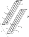
- the device 10 for cooling the battery cells 35 has a plurality of second cooling plates 14 which are designed in accordance with the invention. So are how 1 can be removed, which shows the device 10 for cooling the battery, in each battery cell level 11, 12 several, four in the embodiment shown, second cooling plates 14 are arranged.
- the second cooling plates 14, like the first cooling plate 13, have the cooling fluid flowing through them, with each of the second cooling plates 14 being in thermal contact with a plurality of battery cells 35 of the respective battery cell level 11, 12, in such a way that each of the second cooling plates 14 is on each side the same with a respective row of battery cells 35 is in thermal contact.
- the two in 1 Battery cells 35 shown are in thermal contact with the front second cooling plate 14 of the upper battery cell level 11 .
- the device 10 also has a cooling fluid inlet (not visible) or cooling fluid inlet and a cooling fluid outlet 15 or cooling fluid outlet. In 1 only the cooling fluid outlet 15 is visible. Cooling fluid flows into the first cooling plate 13 , namely the flow channels of the first cooling plate 13 , via the cooling fluid inlet (not visible). A first part of this cooling fluid flowing into the first cooling plate 13 via the cooling fluid inlet flows exclusively through the first cooling plate 13 in the direction of the opposite, second side of the first cooling plate 13, in order to be discharged on this opposite, second side of the first cooling plate 13 via the cooling fluid outlet 15 from the first cooling plate 13 to flow out.
- a second part of the cooling fluid flowing into the first cooling plate 13 via the cooling fluid inlet flows on the first side of the first cooling plate 13 from the first cooling plate 13 into the second cooling plates 14, flows through the second cooling plates 14 and flows on the second, opposite side side of the first cooling plate 13 from the second cooling plates 14 back into the first cooling plate 13, in order to then flow out again on the second side of the first cooling plate 13 via the cooling fluid outlet 15 from the first cooling plate 13 and thus out of the device 10 for cooling the battery cells 35.
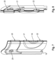
- the second cooling plates 14 In the longitudinal direction, ie between a first side 16 of the respective second cooling plate 14 and an opposite second side 17 of the respective second cooling plate 14, the second cooling plates 14 have a corrugated course or a corrugated contour. This wavy course or the wavy contour of the second cooling plates 14 is adapted to the contour of the battery cells 35 to be cooled, which extend in rows along the second cooling plates 14 .
- the second cooling plates 14 On the opposite sides of the second cooling plates 14, the same have a coolant inlet 18 and a coolant outlet 19, namely on a first side 16 a coolant inlet 18 and on an opposite second side 17 a coolant outlet 19.
- the respective coolant inlet 18 can be used for the second Part of the cooling fluid flowing into the first cooling plate 13 flows from the first cooling plate 13 into the respective second cooling plate 14 . After flowing through the respective second cooling plates 14 , the cooling fluid can exit via the respective coolant outlet 19 and flow back into the first cooling plate 13 in order to then be discharged via the cooling fluid outlet 15 .
- the respective second cooling plate 14 is longitudinally located between the first side 16 and the second Page 17 extending cooling channels 20, 21, 22.
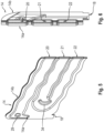
- the respective second cooling plate 14 is how best the exploded view of 4 can be removed, formed of a first plate body 14a and a second plate body 14b.
- the two plate bodies 14a, 14b form both the above-mentioned coolant inlet 18 and the above-mentioned coolant outlet 19 as well as the above-mentioned coolant channels 20, 21, 22.
- the respective second cooling plate 14 is therefore formed by only two assemblies, namely by the two plate bodies 14a, 14b.
- the two plate bodies 14a, 14b define and form both the coolant inlet 18 and the coolant outlet 19 of the respective second cooling plate 14, as well as the coolant channels 20, 21, 22 of the respective second cooling plate 14, which extend in the longitudinal direction of the respective second cooling plate 14.
- the coolant inlet 18 , the coolant outlet 19 and the coolant channels 20, 21, 22 are integral components of the plate bodies 14a, 14b of the respective second cooling plate 14.
- the coolant inlet 18, the coolant outlet 19 and the coolant channels 20, 21 and 22 of the respective second cooling plate 14 are delimited in sections by sections of the plate bodies 14a, 14b which abut and are connected to one another.
- these portions of the plate bodies 14a, 14b that rest against one another and are connected to one another are formed by elevations 23, 24 of the plate bodies 14a, 14b.
- elevations 23, 24 of the plate bodies 14a, 14b depressions 25, 26 extend, which do not abut one another but rather are spaced apart and enclose the coolant inlet 18, the coolant outlet 19 and the coolant channels 20, 21 and 22.
- an oval element 29 is formed in the transition area 27 and a round element 30 is formed in the transition area 28 .
- These elements 29 and 30 increase the stability of the respective second cooling plate 14 in the respective transition region 27 and 28.
- these elements 29, 30 prevent the two plate bodies 14a, 14b from moving away from one another at high fluid pressure and the respective second cooling plate 14 from being deformed or bloated. Furthermore, these elements 29 and 30 promote the flow guidance of the cooling fluid in the respective transition area 27 and 28.
- In 4 is also in a transition area 31 between the first coolant channel 20 and the second coolant channel 21, which is formed in the area of the second side 17 of the respective second cooling plate 14, as well as in a transition area 32 between the second coolant channel 21 and the third coolant channel 22, the is formed in the region of the first side 16 of the respective second cooling plate 14, in each case an element 33, 34 is formed, which in the transition regions 31, 32 the mechanical stability of the respective second Cooling plate 14 increased and the flow of the cooling fluid in the respective transition area 31, 32 improved.
- these elements 33, 34 are formed by bent or curved, in particular sickle-shaped, sections of the plate bodies 14a, 14b, which in turn are provided by the elevations 23, 24 of the plate bodies 14a, 14b.
- the respective second cooling plate 14 is formed by only two assemblies, namely by the two plate bodies 14a, 14b.
- the plate bodies 14a, 14b are bodies made of stamped metal sheets that are soldered together.
- the invention relates both to a cooling plate 14 alone and to a battery module which has a plurality of cooling plates 14 of this type.
- the cooling plates designed according to the invention form the second cooling plates 14 of the device 10 for cooling the battery cells 35.
- a cooling plate 14 At least one metal sheet is provided, the plate bodies 14a, 14b being formed from the at least one metal sheet by stamping.
- the plate bodies 14a, 14b can be brought into the corrugated shape.
- the plate bodies 14a, 14b formed by punching are connected to one another, namely by soldering.
- a soldering paste is applied to the elevations of the plate bodies 14a, 14b, which abut one another after manufacture and are connected to one another.
- the plate bodies 14a, 14b are connected to one another over their entire surface in the area of their adjoining elevations 23 and 24, specifically also in the area of the elements 29, 30, 33 and 34.
- the cooling plate according to the invention and thus the device for cooling the battery cells of a battery module and thus the battery module has a structure and can be manufactured easily.
Landscapes
- Engineering & Computer Science (AREA)
- Manufacturing & Machinery (AREA)
- Chemical & Material Sciences (AREA)
- Chemical Kinetics & Catalysis (AREA)
- Electrochemistry (AREA)
- General Chemical & Material Sciences (AREA)
- Mechanical Engineering (AREA)
- Life Sciences & Earth Sciences (AREA)
- Sustainable Energy (AREA)
- Power Engineering (AREA)
- Transportation (AREA)
- Sustainable Development (AREA)
- Secondary Cells (AREA)
Applications Claiming Priority (1)
| Application Number | Priority Date | Filing Date | Title |
|---|---|---|---|
| DE102021133513.2A DE102021133513A1 (de) | 2021-12-16 | 2021-12-16 | Kühlplatte eines Batteriemoduls einer Traktionsbatterie eines Kraftfahrzeugs, Verfahren zum Herstellen desselben und Batteriemodul |
Publications (2)
| Publication Number | Publication Date |
|---|---|
| EP4199192A2 true EP4199192A2 (fr) | 2023-06-21 |
| EP4199192A3 EP4199192A3 (fr) | 2023-07-26 |
Family
ID=84361438
Family Applications (1)
| Application Number | Title | Priority Date | Filing Date |
|---|---|---|---|
| EP22209353.6A Pending EP4199192A3 (fr) | 2021-12-16 | 2022-11-24 | Plaque de refroidissement d'un module de batterie d'une batterie de traction d'un véhicule automobile, son procédé de fabrication et module de batterie |
Country Status (4)
| Country | Link |
|---|---|
| US (1) | US20230198049A1 (fr) |
| EP (1) | EP4199192A3 (fr) |
| CN (1) | CN116345016A (fr) |
| DE (1) | DE102021133513A1 (fr) |
Citations (4)
| Publication number | Priority date | Publication date | Assignee | Title |
|---|---|---|---|---|
| DE202012006560U1 (de) | 2012-05-17 | 2012-08-02 | Asia Vital Components Co., Ltd. | Wasserkühlplatte für Batteriesatz |
| DE112015000600T5 (de) | 2014-01-30 | 2016-11-10 | Dana Canada Corporation | Wärmetauscher mit abgestimmtem Durchfluss zum Batterie-Thermomanagement |
| CN207250677U (zh) | 2017-04-26 | 2018-04-17 | 天津市捷威动力工业有限公司 | 一种冲压冷板形式的液冷板结构 |
| CN207967246U (zh) | 2018-03-27 | 2018-10-12 | 浙江吉利汽车研究院有限公司 | 液冷板组件及汽车电池系统 |
Family Cites Families (10)
| Publication number | Priority date | Publication date | Assignee | Title |
|---|---|---|---|---|
| DE2903685A1 (de) | 1979-01-31 | 1980-08-14 | Siemens Ag | Kuehlvorrichtung zur kuehlung von elektrischen bauelementen, insbesondere von integrierten bausteinen |
| JPH03504761A (ja) | 1989-02-03 | 1991-10-17 | ザポロジスキイ アフトモビルニイ ザボト “コミュナル”(プロイズボドストベンノエ オビエディネニエ “アフトザズ”) | プレート形熱交換器 |
| US6318455B1 (en) | 1999-07-14 | 2001-11-20 | Mitsubishi Heavy Industries, Ltd. | Heat exchanger |
| US20110206964A1 (en) | 2010-02-24 | 2011-08-25 | Gm Global Technology Operations, Inc. | Cooling system for a battery assembly |
| US8835039B2 (en) * | 2011-10-21 | 2014-09-16 | Avl Powertrain Engineering, Inc. | Battery cooling plate and cooling system |
| CN104204555B (zh) | 2012-02-18 | 2017-02-22 | 江森自控先进能源动力系统有限责任公司 | 一种具有第一构件和第二构件的组件以及制造这种组件的方法 |
| WO2014171095A1 (fr) | 2013-04-16 | 2014-10-23 | パナソニック株式会社 | Echangeur de chaleur |
| GB2549512C (en) * | 2016-04-20 | 2022-01-12 | Delta Motorsport Ltd | Cell pack thermal management apparatus and method |
| CN208589511U (zh) * | 2018-06-29 | 2019-03-08 | 威马智慧出行科技(上海)有限公司 | 一种换热装置 |
| KR20210130443A (ko) * | 2020-04-22 | 2021-11-01 | 주식회사 엘지에너지솔루션 | 전지 모듈 및 이를 포함하는 전지 팩 |
-
2021
- 2021-12-16 DE DE102021133513.2A patent/DE102021133513A1/de active Pending
-
2022
- 2022-11-24 EP EP22209353.6A patent/EP4199192A3/fr active Pending
- 2022-12-01 CN CN202211526106.6A patent/CN116345016A/zh active Pending
- 2022-12-12 US US18/079,168 patent/US20230198049A1/en active Pending
Patent Citations (4)
| Publication number | Priority date | Publication date | Assignee | Title |
|---|---|---|---|---|
| DE202012006560U1 (de) | 2012-05-17 | 2012-08-02 | Asia Vital Components Co., Ltd. | Wasserkühlplatte für Batteriesatz |
| DE112015000600T5 (de) | 2014-01-30 | 2016-11-10 | Dana Canada Corporation | Wärmetauscher mit abgestimmtem Durchfluss zum Batterie-Thermomanagement |
| CN207250677U (zh) | 2017-04-26 | 2018-04-17 | 天津市捷威动力工业有限公司 | 一种冲压冷板形式的液冷板结构 |
| CN207967246U (zh) | 2018-03-27 | 2018-10-12 | 浙江吉利汽车研究院有限公司 | 液冷板组件及汽车电池系统 |
Also Published As
| Publication number | Publication date |
|---|---|
| EP4199192A3 (fr) | 2023-07-26 |
| CN116345016A (zh) | 2023-06-27 |
| DE102021133513A1 (de) | 2023-06-22 |
| US20230198049A1 (en) | 2023-06-22 |
Similar Documents
| Publication | Publication Date | Title |
|---|---|---|
| EP1271085B1 (fr) | Dispositif pour refroidir un équipement de véhicule, en particulier batterie ou pile à combustible | |
| EP3096372B1 (fr) | Module de batterie et systeme de batterie | |
| DE10321916B4 (de) | Separatoreinheit und Brennstoffzelle mit Separatoreinheit | |
| DE102019200465A1 (de) | Batteriekühlplatte mit integrierten Entlüftungsöffnungen | |
| EP2377184B1 (fr) | Dispositif d'alimentation en tension pour un véhicule avec une dissipation thermique améliorée | |
| DE112016000129B4 (de) | Wärmetauscher zum Kühlen eines elektrischen Elements, sowie Wärmetauscheranordnung und Kühlmodul | |
| EP2541669B1 (fr) | Dispositif de refroidissement pour batterie de véhicule, batterie de véhicule et procédé de fabrication d'un dispositif de refroidissement | |
| WO2007076985A2 (fr) | Echangeur thermique a plaques d'echangeur thermique formees par emboutissage profond | |
| DE102018210444B3 (de) | Hochvoltbatterie für ein Kraftfahrzeug sowie Kraftfahrzeug | |
| DE102011078897A1 (de) | Temperiervorrichtung zum Temperieren einer Batterie und Verfahren zur Herstellung einer Temperiervorrichtung | |
| EP3878024A1 (fr) | Connecteur de cellules servant à relier de manière électroconductrice des cellules rondes d'une batterie pour un véhicule automobile, et procédé de fabrication d'une batterie pour un véhicule automobile | |
| DE112014004189T5 (de) | Wärmetauscher zum Kühlen eines elektrischen Bauteils | |
| EP1627441B1 (fr) | Pile a combustible et systeme de chauffage de pile a combustible | |
| DE112021004495T5 (de) | Komponenten für Batterien | |
| DE102013219665B4 (de) | Kühlanordnung | |
| DE102018112475B4 (de) | Batterieanordnung und herstellverfahren | |
| DE112018002794T5 (de) | Wärmetauscher zum Kühlen einer elektrischen Vorrichtung | |
| DE102014112627A1 (de) | Batteriemodul | |
| EP4120437A1 (fr) | Dispositif de refroidissement des éléments de batterie d'une batterie de traction d'un véhicule automobile et batterie de traction | |
| EP4199192A2 (fr) | Plaque de refroidissement d'un module de batterie d'une batterie de traction d'un véhicule automobile, son procédé de fabrication et module de batterie | |
| DE102017211286A1 (de) | Kühlvorrichtung zum Kühlen zumindest zweier Batteriemodule | |
| DE102011005236A1 (de) | Sammelrohr, Wärmetauscher und Verfahren zum Herstellen eines Sammelrohres | |
| DE102018208232A1 (de) | Bauteil mit einer durch ein Einlegeelement optimierten Kühlleistung und Kraftfahrzeug mit zumindest einem Bauteil | |
| DE202018105617U1 (de) | Separatorplatte und elektrochemisches System | |
| EP3465797A1 (fr) | Batterie |
Legal Events
| Date | Code | Title | Description |
|---|---|---|---|
| PUAI | Public reference made under article 153(3) epc to a published international application that has entered the european phase |
Free format text: ORIGINAL CODE: 0009012 |
|
| STAA | Information on the status of an ep patent application or granted ep patent |
Free format text: STATUS: THE APPLICATION HAS BEEN PUBLISHED |
|
| AK | Designated contracting states |
Kind code of ref document: A2 Designated state(s): AL AT BE BG CH CY CZ DE DK EE ES FI FR GB GR HR HU IE IS IT LI LT LU LV MC ME MK MT NL NO PL PT RO RS SE SI SK SM TR |
|
| PUAL | Search report despatched |
Free format text: ORIGINAL CODE: 0009013 |
|
| AK | Designated contracting states |
Kind code of ref document: A3 Designated state(s): AL AT BE BG CH CY CZ DE DK EE ES FI FR GB GR HR HU IE IS IT LI LT LU LV MC ME MK MT NL NO PL PT RO RS SE SI SK SM TR |
|
| RIC1 | Information provided on ipc code assigned before grant |
Ipc: H01M 10/6557 20140101ALI20230621BHEP Ipc: H01M 10/643 20140101ALI20230621BHEP Ipc: H01M 10/625 20140101ALI20230621BHEP Ipc: H01M 10/613 20140101ALI20230621BHEP Ipc: H01M 10/6556 20140101ALI20230621BHEP Ipc: H01M 10/6555 20140101AFI20230621BHEP |
|
| STAA | Information on the status of an ep patent application or granted ep patent |
Free format text: STATUS: REQUEST FOR EXAMINATION WAS MADE |
|
| 17P | Request for examination filed |
Effective date: 20240124 |
|
| RBV | Designated contracting states (corrected) |
Designated state(s): AL AT BE BG CH CY CZ DE DK EE ES FI FR GB GR HR HU IE IS IT LI LT LU LV MC ME MK MT NL NO PL PT RO RS SE SI SK SM TR |