EP4199192A2 - Cooling plate of a battery module of a traction battery of a motor vehicle, method for producing the same, and battery module - Google Patents
Cooling plate of a battery module of a traction battery of a motor vehicle, method for producing the same, and battery module Download PDFInfo
- Publication number
- EP4199192A2 EP4199192A2 EP22209353.6A EP22209353A EP4199192A2 EP 4199192 A2 EP4199192 A2 EP 4199192A2 EP 22209353 A EP22209353 A EP 22209353A EP 4199192 A2 EP4199192 A2 EP 4199192A2
- Authority
- EP
- European Patent Office
- Prior art keywords
- coolant
- plate
- cooling
- battery
- cooling plate
- Prior art date
- Legal status (The legal status is an assumption and is not a legal conclusion. Google has not performed a legal analysis and makes no representation as to the accuracy of the status listed.)
- Pending
Links
- 238000001816 cooling Methods 0.000 title claims abstract description 140
- 238000004519 manufacturing process Methods 0.000 title claims description 8
- 239000002826 coolant Substances 0.000 claims abstract description 121
- 230000007704 transition Effects 0.000 claims description 20
- 239000002184 metal Substances 0.000 claims description 7
- 230000000712 assembly Effects 0.000 claims description 6
- 238000000429 assembly Methods 0.000 claims description 6
- 238000005476 soldering Methods 0.000 claims description 4
- 239000012809 cooling fluid Substances 0.000 description 21
- XLYOFNOQVPJJNP-UHFFFAOYSA-N water Substances O XLYOFNOQVPJJNP-UHFFFAOYSA-N 0.000 description 5
- 238000000034 method Methods 0.000 description 2
- 238000010146 3D printing Methods 0.000 description 1
- 101100004280 Caenorhabditis elegans best-2 gene Proteins 0.000 description 1
- 238000006243 chemical reaction Methods 0.000 description 1
- 230000001419 dependent effect Effects 0.000 description 1
- 238000011161 development Methods 0.000 description 1
- 230000018109 developmental process Effects 0.000 description 1
- 239000012530 fluid Substances 0.000 description 1
- 238000010438 heat treatment Methods 0.000 description 1
- 238000013021 overheating Methods 0.000 description 1
- 238000004080 punching Methods 0.000 description 1
- 238000003466 welding Methods 0.000 description 1
Images


Classifications
-
- H—ELECTRICITY
- H01—ELECTRIC ELEMENTS
- H01M—PROCESSES OR MEANS, e.g. BATTERIES, FOR THE DIRECT CONVERSION OF CHEMICAL ENERGY INTO ELECTRICAL ENERGY
- H01M10/00—Secondary cells; Manufacture thereof
- H01M10/60—Heating or cooling; Temperature control
- H01M10/65—Means for temperature control structurally associated with the cells
- H01M10/655—Solid structures for heat exchange or heat conduction
- H01M10/6556—Solid parts with flow channel passages or pipes for heat exchange
-
- H—ELECTRICITY
- H01—ELECTRIC ELEMENTS
- H01M—PROCESSES OR MEANS, e.g. BATTERIES, FOR THE DIRECT CONVERSION OF CHEMICAL ENERGY INTO ELECTRICAL ENERGY
- H01M10/00—Secondary cells; Manufacture thereof
- H01M10/60—Heating or cooling; Temperature control
- H01M10/65—Means for temperature control structurally associated with the cells
- H01M10/655—Solid structures for heat exchange or heat conduction
- H01M10/6554—Rods or plates
- H01M10/6555—Rods or plates arranged between the cells
-
- B—PERFORMING OPERATIONS; TRANSPORTING
- B21—MECHANICAL METAL-WORKING WITHOUT ESSENTIALLY REMOVING MATERIAL; PUNCHING METAL
- B21C—MANUFACTURE OF METAL SHEETS, WIRE, RODS, TUBES OR PROFILES, OTHERWISE THAN BY ROLLING; AUXILIARY OPERATIONS USED IN CONNECTION WITH METAL-WORKING WITHOUT ESSENTIALLY REMOVING MATERIAL
- B21C37/00—Manufacture of metal sheets, bars, wire, tubes or like semi-manufactured products, not otherwise provided for; Manufacture of tubes of special shape
- B21C37/02—Manufacture of metal sheets, bars, wire, tubes or like semi-manufactured products, not otherwise provided for; Manufacture of tubes of special shape of sheets
-
- B—PERFORMING OPERATIONS; TRANSPORTING
- B60—VEHICLES IN GENERAL
- B60L—PROPULSION OF ELECTRICALLY-PROPELLED VEHICLES; SUPPLYING ELECTRIC POWER FOR AUXILIARY EQUIPMENT OF ELECTRICALLY-PROPELLED VEHICLES; ELECTRODYNAMIC BRAKE SYSTEMS FOR VEHICLES IN GENERAL; MAGNETIC SUSPENSION OR LEVITATION FOR VEHICLES; MONITORING OPERATING VARIABLES OF ELECTRICALLY-PROPELLED VEHICLES; ELECTRIC SAFETY DEVICES FOR ELECTRICALLY-PROPELLED VEHICLES
- B60L50/00—Electric propulsion with power supplied within the vehicle
- B60L50/50—Electric propulsion with power supplied within the vehicle using propulsion power supplied by batteries or fuel cells
- B60L50/60—Electric propulsion with power supplied within the vehicle using propulsion power supplied by batteries or fuel cells using power supplied by batteries
- B60L50/64—Constructional details of batteries specially adapted for electric vehicles
-
- H—ELECTRICITY
- H01—ELECTRIC ELEMENTS
- H01M—PROCESSES OR MEANS, e.g. BATTERIES, FOR THE DIRECT CONVERSION OF CHEMICAL ENERGY INTO ELECTRICAL ENERGY
- H01M10/00—Secondary cells; Manufacture thereof
- H01M10/60—Heating or cooling; Temperature control
- H01M10/61—Types of temperature control
- H01M10/613—Cooling or keeping cold
-
- H—ELECTRICITY
- H01—ELECTRIC ELEMENTS
- H01M—PROCESSES OR MEANS, e.g. BATTERIES, FOR THE DIRECT CONVERSION OF CHEMICAL ENERGY INTO ELECTRICAL ENERGY
- H01M10/00—Secondary cells; Manufacture thereof
- H01M10/60—Heating or cooling; Temperature control
- H01M10/62—Heating or cooling; Temperature control specially adapted for specific applications
- H01M10/625—Vehicles
-
- H—ELECTRICITY
- H01—ELECTRIC ELEMENTS
- H01M—PROCESSES OR MEANS, e.g. BATTERIES, FOR THE DIRECT CONVERSION OF CHEMICAL ENERGY INTO ELECTRICAL ENERGY
- H01M10/00—Secondary cells; Manufacture thereof
- H01M10/60—Heating or cooling; Temperature control
- H01M10/64—Heating or cooling; Temperature control characterised by the shape of the cells
- H01M10/643—Cylindrical cells
-
- H—ELECTRICITY
- H01—ELECTRIC ELEMENTS
- H01M—PROCESSES OR MEANS, e.g. BATTERIES, FOR THE DIRECT CONVERSION OF CHEMICAL ENERGY INTO ELECTRICAL ENERGY
- H01M10/00—Secondary cells; Manufacture thereof
- H01M10/60—Heating or cooling; Temperature control
- H01M10/65—Means for temperature control structurally associated with the cells
- H01M10/655—Solid structures for heat exchange or heat conduction
- H01M10/6556—Solid parts with flow channel passages or pipes for heat exchange
- H01M10/6557—Solid parts with flow channel passages or pipes for heat exchange arranged between the cells
-
- H—ELECTRICITY
- H01—ELECTRIC ELEMENTS
- H01M—PROCESSES OR MEANS, e.g. BATTERIES, FOR THE DIRECT CONVERSION OF CHEMICAL ENERGY INTO ELECTRICAL ENERGY
- H01M10/00—Secondary cells; Manufacture thereof
- H01M10/60—Heating or cooling; Temperature control
- H01M10/65—Means for temperature control structurally associated with the cells
- H01M10/656—Means for temperature control structurally associated with the cells characterised by the type of heat-exchange fluid
- H01M10/6567—Liquids
- H01M10/6568—Liquids characterised by flow circuits, e.g. loops, located externally to the cells or cell casings
-
- H—ELECTRICITY
- H01—ELECTRIC ELEMENTS
- H01M—PROCESSES OR MEANS, e.g. BATTERIES, FOR THE DIRECT CONVERSION OF CHEMICAL ENERGY INTO ELECTRICAL ENERGY
- H01M2220/00—Batteries for particular applications
- H01M2220/20—Batteries in motive systems, e.g. vehicle, ship, plane
-
- H—ELECTRICITY
- H01—ELECTRIC ELEMENTS
- H01M—PROCESSES OR MEANS, e.g. BATTERIES, FOR THE DIRECT CONVERSION OF CHEMICAL ENERGY INTO ELECTRICAL ENERGY
- H01M50/00—Constructional details or processes of manufacture of the non-active parts of electrochemical cells other than fuel cells, e.g. hybrid cells
- H01M50/20—Mountings; Secondary casings or frames; Racks, modules or packs; Suspension devices; Shock absorbers; Transport or carrying devices; Holders
- H01M50/204—Racks, modules or packs for multiple batteries or multiple cells
- H01M50/207—Racks, modules or packs for multiple batteries or multiple cells characterised by their shape
- H01M50/213—Racks, modules or packs for multiple batteries or multiple cells characterised by their shape adapted for cells having curved cross-section, e.g. round or elliptic
-
- Y—GENERAL TAGGING OF NEW TECHNOLOGICAL DEVELOPMENTS; GENERAL TAGGING OF CROSS-SECTIONAL TECHNOLOGIES SPANNING OVER SEVERAL SECTIONS OF THE IPC; TECHNICAL SUBJECTS COVERED BY FORMER USPC CROSS-REFERENCE ART COLLECTIONS [XRACs] AND DIGESTS
- Y02—TECHNOLOGIES OR APPLICATIONS FOR MITIGATION OR ADAPTATION AGAINST CLIMATE CHANGE
- Y02E—REDUCTION OF GREENHOUSE GAS [GHG] EMISSIONS, RELATED TO ENERGY GENERATION, TRANSMISSION OR DISTRIBUTION
- Y02E60/00—Enabling technologies; Technologies with a potential or indirect contribution to GHG emissions mitigation
- Y02E60/10—Energy storage using batteries
Definitions
- the invention relates to a cooling plate of a battery module of a traction battery of a motor vehicle. Furthermore, the invention relates to a method for producing such a cooling plate and a battery module.
- traction batteries are installed, which are used to store electrical energy in order to provide the same to an electrical machine.
- Traction batteries have several battery modules that are electrically interconnected. Each battery module has several battery cells, which are also electrically interconnected. During operation, the battery cells are subject to heating, for example as a result of chemical reactions within the battery cells. In order to avoid damage to the battery modules and thus to the traction battery as a result of overheating of the battery cells, heat must be dissipated from the traction battery by cooling the battery cells. It is already known to cool the battery cells of a traction battery. For this purpose, a battery module of a traction battery has a device for cooling the battery cells.
- the water cooling plate for a battery pack.
- the water cooling plate has a first plate, a second plate, and a channel structure sandwiched between the first plate and the second plate. Furthermore, the water cooling plate has a separate connector that forms a water inlet and a water outlet.
- the two plates as well as the channel structure are formed by stamping, these assemblies being joined together by welding.
- CN 207 967 246 U discloses a cooling device for an automotive battery.
- the cooling device is composed of plates, with a separate inlet and a separate outlet for coolant being formed on an upper plate.
- the cooling plate serves to cool several battery modules.
- the object of the invention is to create a cooling plate for a battery module of a traction battery in a motor vehicle, a method for producing such a cooling plate for a traction battery and a battery module with such cooling plates.
- the cooling plate according to the invention has a first plate body and a second plate body connected to the first plate body.
- the cooling plate according to the invention has a coolant inlet defined or formed by the first plate body and the second plate body on a first side of the cooling plate.
- the cooling plate according to the invention also has a coolant outlet defined or formed by the first plate body and the second plate body on a second side of the cooling plate.
- the cooling plate according to the invention also has coolant channels defined or formed by the first plate body and the second plate body, with a first coolant channel, which is coupled to the coolant inlet, extending from the first side in the direction of the second side, with a second coolant channel coupled to the first coolant channel extending from the second side toward the first side, and a third coolant channel coupled to the second coolant channel and the coolant drain extending from the first side toward the second side extends.
- the cooling plate according to the invention is composed of the first plate body and the second plate body.
- the two plate bodies define or form both the coolant inlet and the coolant outlet as well as the coolant channels extending between the coolant inlet and the coolant outlet.
- the cooling plate according to the invention is therefore formed by only two assemblies, namely by the two plate bodies.
- the cooling plate has a simple structure and can be easily manufactured.
- the coolant inlet, the coolant channels and the coolant outlet are preferably delimited in sections by sections of the plate bodies which abut and are connected to one another.
- the abutting and interconnected sections of the plate bodies are formed by elevations of the plate bodies, depressions of the plate bodies extending between the elevations of the plate bodies, which are spaced apart and enclose the coolant inlet, the coolant channels and the coolant outlet. This allows a particularly simple production of the cooling plate.
- the coolant inlet, the coolant channels and the coolant outlet are preferably integral parts of the plate body.
- the number of assemblies in the cooling plate is reduced to just two, which means that the cooling plate can be manufactured particularly easily.
- the plate bodies are formed from stamped metal sheets that are soldered together. This is particularly preferred in order to easily manufacture the cooling plate according to the invention.
- Round or oval sections of the plate bodies preferably adjoin and are connected to one another in a transition area between the coolant inlet and the first coolant channel and/or in a transition area between the third coolant channel and the coolant outlet.
- the round or oval sections favor an advantageous flow guidance in the respective transition area, on the other hand, they give the cooling plate a high degree of stability, even at high flow pressures.
- bent or curved, in particular sickle-shaped, sections of the plate bodies preferably adjoin and are connected to one another.
- the bent or curved, in particular sickle-shaped, sections also promote the flow guidance of the cooling fluid and give the cooling plate a high level of stability even at high flow pressures.
- the battery module according to the invention is defined in claim 9.
- the method according to the invention for producing a cooling plate of a battery module of a traction battery is defined in claim 10.
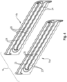
- FIG. 1 shows a perspective view of a preferred embodiment of a device 10 for cooling battery cells 35 of a battery module of a traction battery of a motor vehicle. In 1 only two battery cells 35 are shown.
- the arrangement of 1 can be accommodated in a module housing (not shown) of the battery module.
- the battery cells 35 are arranged in two battery cell planes 11, 12 arranged one above the other.
- a plurality of battery cells 35 are arranged in a first or upper battery cell level 11 and in a second or lower battery cell level 12 .
- in 1 only two battery cells 35 are shown, both of which are arranged in the upper battery cell level 11 .
- the device 10 for cooling the battery cells 35 has a first cooling plate 13 which is arranged between the first battery cell level 11 and the second battery cell level 12 and which, via its outer sides, is in thermal contact with the battery cells 35 of the first battery cell level 11 and in thermal contact with the battery cells 35 of the second battery cell level 12 is available.
- the first cooling plate 13 is in thermal contact with an underside of the battery cells 35 of the first battery cell level 11 via a first outer side and with an upper side of the battery cells 35 of the second battery cell level 12 via a second outer side.
- Electrical contacts (not shown) of the battery cells 35 are formed on the upper side of the battery cells 35 in the first battery cell level 11 and on the underside of the battery cells 35 in the second battery cell level 12 . Those sides of the respective battery cell 35 on which electrical contacts (not shown) of the battery cells are formed therefore face away from the first cooling plate 13 .
- the battery cells 35 of the battery module are therefore in contact with the sides facing away from the electrical contacts of the battery cells 35 on the first cooling plate 13 of the cooling device 10, namely on the outer sides of the first cooling plate 13.
- the first cooling plate 13 can have a sandwich-like structure, preferably made up of three plate bodies. It is possible that the first cooling plate 13 is also formed by only two plate bodies. Also, the first cooling plate 13 may be a monolithic assembly made, for example, by 3D printing. When the first cooling plate 13 is formed from two plate bodies, these plate bodies form the outer sides of the first cooling plate 13, via which the first cooling plate 12 is in thermal contact with the battery cells of the two battery cell planes. These two plate bodies then define the flow channels of the first cooling plate 13 for the cooling medium.
- the device 10 for cooling the battery cells 35 has a plurality of second cooling plates 14 which are designed in accordance with the invention. So are how 1 can be removed, which shows the device 10 for cooling the battery, in each battery cell level 11, 12 several, four in the embodiment shown, second cooling plates 14 are arranged.
- the second cooling plates 14, like the first cooling plate 13, have the cooling fluid flowing through them, with each of the second cooling plates 14 being in thermal contact with a plurality of battery cells 35 of the respective battery cell level 11, 12, in such a way that each of the second cooling plates 14 is on each side the same with a respective row of battery cells 35 is in thermal contact.
- the two in 1 Battery cells 35 shown are in thermal contact with the front second cooling plate 14 of the upper battery cell level 11 .
- the device 10 also has a cooling fluid inlet (not visible) or cooling fluid inlet and a cooling fluid outlet 15 or cooling fluid outlet. In 1 only the cooling fluid outlet 15 is visible. Cooling fluid flows into the first cooling plate 13 , namely the flow channels of the first cooling plate 13 , via the cooling fluid inlet (not visible). A first part of this cooling fluid flowing into the first cooling plate 13 via the cooling fluid inlet flows exclusively through the first cooling plate 13 in the direction of the opposite, second side of the first cooling plate 13, in order to be discharged on this opposite, second side of the first cooling plate 13 via the cooling fluid outlet 15 from the first cooling plate 13 to flow out.
- a second part of the cooling fluid flowing into the first cooling plate 13 via the cooling fluid inlet flows on the first side of the first cooling plate 13 from the first cooling plate 13 into the second cooling plates 14, flows through the second cooling plates 14 and flows on the second, opposite side side of the first cooling plate 13 from the second cooling plates 14 back into the first cooling plate 13, in order to then flow out again on the second side of the first cooling plate 13 via the cooling fluid outlet 15 from the first cooling plate 13 and thus out of the device 10 for cooling the battery cells 35.
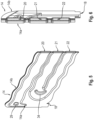
- the second cooling plates 14 In the longitudinal direction, ie between a first side 16 of the respective second cooling plate 14 and an opposite second side 17 of the respective second cooling plate 14, the second cooling plates 14 have a corrugated course or a corrugated contour. This wavy course or the wavy contour of the second cooling plates 14 is adapted to the contour of the battery cells 35 to be cooled, which extend in rows along the second cooling plates 14 .
- the second cooling plates 14 On the opposite sides of the second cooling plates 14, the same have a coolant inlet 18 and a coolant outlet 19, namely on a first side 16 a coolant inlet 18 and on an opposite second side 17 a coolant outlet 19.
- the respective coolant inlet 18 can be used for the second Part of the cooling fluid flowing into the first cooling plate 13 flows from the first cooling plate 13 into the respective second cooling plate 14 . After flowing through the respective second cooling plates 14 , the cooling fluid can exit via the respective coolant outlet 19 and flow back into the first cooling plate 13 in order to then be discharged via the cooling fluid outlet 15 .
- the respective second cooling plate 14 is longitudinally located between the first side 16 and the second Page 17 extending cooling channels 20, 21, 22.
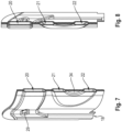
- the respective second cooling plate 14 is how best the exploded view of 4 can be removed, formed of a first plate body 14a and a second plate body 14b.
- the two plate bodies 14a, 14b form both the above-mentioned coolant inlet 18 and the above-mentioned coolant outlet 19 as well as the above-mentioned coolant channels 20, 21, 22.
- the respective second cooling plate 14 is therefore formed by only two assemblies, namely by the two plate bodies 14a, 14b.
- the two plate bodies 14a, 14b define and form both the coolant inlet 18 and the coolant outlet 19 of the respective second cooling plate 14, as well as the coolant channels 20, 21, 22 of the respective second cooling plate 14, which extend in the longitudinal direction of the respective second cooling plate 14.
- the coolant inlet 18 , the coolant outlet 19 and the coolant channels 20, 21, 22 are integral components of the plate bodies 14a, 14b of the respective second cooling plate 14.
- the coolant inlet 18, the coolant outlet 19 and the coolant channels 20, 21 and 22 of the respective second cooling plate 14 are delimited in sections by sections of the plate bodies 14a, 14b which abut and are connected to one another.
- these portions of the plate bodies 14a, 14b that rest against one another and are connected to one another are formed by elevations 23, 24 of the plate bodies 14a, 14b.
- elevations 23, 24 of the plate bodies 14a, 14b depressions 25, 26 extend, which do not abut one another but rather are spaced apart and enclose the coolant inlet 18, the coolant outlet 19 and the coolant channels 20, 21 and 22.
- an oval element 29 is formed in the transition area 27 and a round element 30 is formed in the transition area 28 .
- These elements 29 and 30 increase the stability of the respective second cooling plate 14 in the respective transition region 27 and 28.
- these elements 29, 30 prevent the two plate bodies 14a, 14b from moving away from one another at high fluid pressure and the respective second cooling plate 14 from being deformed or bloated. Furthermore, these elements 29 and 30 promote the flow guidance of the cooling fluid in the respective transition area 27 and 28.
- In 4 is also in a transition area 31 between the first coolant channel 20 and the second coolant channel 21, which is formed in the area of the second side 17 of the respective second cooling plate 14, as well as in a transition area 32 between the second coolant channel 21 and the third coolant channel 22, the is formed in the region of the first side 16 of the respective second cooling plate 14, in each case an element 33, 34 is formed, which in the transition regions 31, 32 the mechanical stability of the respective second Cooling plate 14 increased and the flow of the cooling fluid in the respective transition area 31, 32 improved.
- these elements 33, 34 are formed by bent or curved, in particular sickle-shaped, sections of the plate bodies 14a, 14b, which in turn are provided by the elevations 23, 24 of the plate bodies 14a, 14b.
- the respective second cooling plate 14 is formed by only two assemblies, namely by the two plate bodies 14a, 14b.
- the plate bodies 14a, 14b are bodies made of stamped metal sheets that are soldered together.
- the invention relates both to a cooling plate 14 alone and to a battery module which has a plurality of cooling plates 14 of this type.
- the cooling plates designed according to the invention form the second cooling plates 14 of the device 10 for cooling the battery cells 35.
- a cooling plate 14 At least one metal sheet is provided, the plate bodies 14a, 14b being formed from the at least one metal sheet by stamping.
- the plate bodies 14a, 14b can be brought into the corrugated shape.
- the plate bodies 14a, 14b formed by punching are connected to one another, namely by soldering.
- a soldering paste is applied to the elevations of the plate bodies 14a, 14b, which abut one another after manufacture and are connected to one another.
- the plate bodies 14a, 14b are connected to one another over their entire surface in the area of their adjoining elevations 23 and 24, specifically also in the area of the elements 29, 30, 33 and 34.
- the cooling plate according to the invention and thus the device for cooling the battery cells of a battery module and thus the battery module has a structure and can be manufactured easily.
Abstract
Kühlplatte (14) eines Batteriemoduls einer Traktionsbatterie eines Kraftfahrzeugs zur Kühlung von Batteriezellen des Batteriemoduls, mit einem ersten Plattenkörper (14a) und einem mit dem ersten Plattenkörper (14a) verbundenen zweiten Plattenkörper, mit einem von dem ersten Plattenkörper (14a) und dem zweiten Plattenkörper an einer ersten Seite (16) der Kühlplatte gebildeten Kühlmittelzulauf (18), mit einem von dem ersten Plattenkörper (14a) und dem zweiten Plattenkörper an einer zweiten Seite (17) der Kühlplatte gebildeten Kühlmittelablauf (19), mit von dem ersten Plattenkörper (14a) und dem zweiten Plattenkörper (14b) gebildeten Kühlmittelkanälen (20, 21, 22), wobei sich ein erster Kühlmittelkanal (20), der mit dem Kühlmittelzulauf (18) gekoppelt ist, ausgehend von der ersten Seite (16) in Richtung auf die zweite Seite (17) erstreckt, wobei sich ein zweiter Kühlmittelkanal (21), der mit dem ersten Kühlmittelkanal (20) gekoppelt ist, ausgehend von der zweiten Seite (17) in Richtung auf die erste Seite (16) erstreckt, und wobei sich ein dritter Kühlmittelkanal (22), der mit dem zweiten Kühlmittelkanal (21) und dem Kühlmittelablauf (19) gekoppelt ist, ausgehend von der ersten Seite (16) in Richtung auf die zweite Seite (17) erstreckt.Cooling plate (14) of a battery module of a traction battery of a motor vehicle for cooling battery cells of the battery module, with a first plate body (14a) and a second plate body connected to the first plate body (14a), with one of the first plate body (14a) and the second plate body coolant inlet (18) formed on a first side (16) of the cooling plate, with a coolant outlet (19) formed by the first plate body (14a) and the second plate body on a second side (17) of the cooling plate, with coolant outlet (19) formed by the first plate body (14a ) and the second plate body (14b) formed coolant channels (20, 21, 22), wherein a first coolant channel (20), which is coupled to the coolant inlet (18), starting from the first side (16) in the direction of the second Side (17) extends, wherein a second coolant channel (21), which is coupled to the first coolant channel (20), starting from the second side (17) towards the first side (16), and wherein a third Coolant channel (22), which is coupled to the second coolant channel (21) and the coolant outlet (19), starting from the first side (16) towards the second side (17).
Description
Die Erfindung betrifft eine Kühlplatte eines Batteriemoduls einer Traktionsbatterie eines Kraftfahrzeugs. Ferner betrifft die Erfindung ein Verfahren zum Herstellen einer solchen Kühlplatte und ein Batteriemodul.The invention relates to a cooling plate of a battery module of a traction battery of a motor vehicle. Furthermore, the invention relates to a method for producing such a cooling plate and a battery module.
In Kraftfahrzeugen, wie zum Beispiel in Hybridfahrzeugen oder auch Elektrofahrzeugen, sind Traktionsbatterien verbaut, die der Speicherung elektrischer Energie dienen, um dieselbe einer elektrischen Maschine bereitzustellen. Traktionsbatterien verfügen über mehrere Batteriemodule, die untereinander elektrisch verschaltet sind. Jedes Batteriemodul verfügt über mehrere Batteriezellen, die auch untereinander elektrisch verschaltet sind. Im Betrieb unterliegen die Batteriezellen, zum Beispiel infolge von chemischen Reaktionen innerhalb der Batteriezellen, einer Erwärmung. Um eine Beschädigung der Batteriemodule und damit der Traktionsbatterie infolge von einer Überhitzung der Batteriezellen zu vermeiden, muss durch Kühlung der Batteriezellen Wärme von der Traktionsbatterie abgeführt werden. Es ist bereits bekannt, die Batteriezellen einer Traktionsbatterie zu kühlen. Hierzu verfügt ein Batteriemodul einer Traktionsbatterie einer Vorrichtung zur Kühlung der Batteriezellen.In motor vehicles, such as hybrid vehicles or electric vehicles, traction batteries are installed, which are used to store electrical energy in order to provide the same to an electrical machine. Traction batteries have several battery modules that are electrically interconnected. Each battery module has several battery cells, which are also electrically interconnected. During operation, the battery cells are subject to heating, for example as a result of chemical reactions within the battery cells. In order to avoid damage to the battery modules and thus to the traction battery as a result of overheating of the battery cells, heat must be dissipated from the traction battery by cooling the battery cells. It is already known to cool the battery cells of a traction battery. For this purpose, a battery module of a traction battery has a device for cooling the battery cells.
Aus
Es besteht Bedarf an einer Kühlplatte eines Batteriemoduls einer Traktionsbatterie zur Kühlung mehrerer Batteriezellen des Batteriemoduls, die über einen einfachen Aufbau verfügt und einfach hergestellt werden kann. Ferner besteht Bedarf an einem Batteriemodul mit einer solchen Kühlplatte und einem Verfahren zum Herstellen der Kühlplatte.There is a need for a cooling plate of a battery module of a traction battery for cooling multiple battery cells of the battery module, which has a simple structure and can be easily manufactured. There is also a need for a battery module with such a cooling plate and a method for manufacturing the cooling plate.
Aufgabe der Erfindung ist es, eine Kühlplatte eines Batteriemoduls einer Traktionsbatterie eines Kraftfahrzeugs, ein Verfahren zum Herstellen einer solchen Kühlplatte einer Traktionsbatterie und ein Batteriemodul mit solchen Kühlplatten zu schaffen.The object of the invention is to create a cooling plate for a battery module of a traction battery in a motor vehicle, a method for producing such a cooling plate for a traction battery and a battery module with such cooling plates.
Diese Aufgabe wird durch eine Kühlplatte eines Batteriemoduls einer Traktionsbatterie eines Kraftfahrzeugs nach Anspruch 1.This object is achieved by a cooling plate of a battery module of a traction battery of a motor vehicle according to claim 1.
Die erfindungsgemäße Kühlplatte weist einen ersten Plattenkörper und einen mit dem ersten Plattenkörper verbundenen zweiten Plattenkörper auf. Die erfindungsgemäße Kühlplatte weist einen von dem ersten Plattenkörper und dem zweiten Plattenkörper an einer ersten Seite der Kühlplatte definierten oder gebildeten Kühlmittelzulauf auf. Die erfindungsgemäße Kühlplatte weist ferner einen von dem ersten Plattenkörper und dem zweiten Plattenkörper an einer zweiten Seite der Kühlplatte definierten oder gebildeten Kühlmittelablauf auf. Die erfindungsgemäße Kühlplatte weist ferner von dem ersten Plattenkörper und dem zweiten Plattenkörper definierte oder gebildete Kühlmittelkanäle auf, wobei sich ein erster Kühlmittelkanal, der mit dem Kühlmittelzulauf gekoppelt ist, ausgehend von der ersten Seite in Richtung auf die zweite Seite erstreckt, wobei sich ein zweiter Kühlmittelkanal, der mit dem ersten Kühlmittelkanal gekoppelt ist, ausgehend von der zweiten Seite in Richtung auf die erste Seite erstreckt, und wobei sich ein dritter Kühlmittelkanal, der mit dem zweiten Kühlmittelkanal und dem Kühlmittelablauf gekoppelt ist, ausgehend von der ersten Seite in Richtung auf die zweite Seite erstreckt.The cooling plate according to the invention has a first plate body and a second plate body connected to the first plate body. The cooling plate according to the invention has a coolant inlet defined or formed by the first plate body and the second plate body on a first side of the cooling plate. The cooling plate according to the invention also has a coolant outlet defined or formed by the first plate body and the second plate body on a second side of the cooling plate. The cooling plate according to the invention also has coolant channels defined or formed by the first plate body and the second plate body, with a first coolant channel, which is coupled to the coolant inlet, extending from the first side in the direction of the second side, with a second coolant channel coupled to the first coolant channel extending from the second side toward the first side, and a third coolant channel coupled to the second coolant channel and the coolant drain extending from the first side toward the second side extends.
Die erfindungsgemäße Kühlplatte ist aus dem ersten Plattenkörper und dem zweiten Plattenkörper zusammengesetzt. Die beiden Plattenkörper definieren oder bilden sowohl den Kühlmittelzulauf als auch den Kühlmittelablauf sowie die sich zwischen dem Kühlmittelzulauf und dem Kühlmittelablauf erstreckenden Kühlmittelkanäle. Die erfindungsgemäße Kühlplatte ist demnach von lediglich zwei Baugruppen gebildet, nämlich von den beiden Plattenkörpern. Die Kühlplatte verfügt aber über einen einfachen Aufbau und kann einfach hergestellt werden.The cooling plate according to the invention is composed of the first plate body and the second plate body. The two plate bodies define or form both the coolant inlet and the coolant outlet as well as the coolant channels extending between the coolant inlet and the coolant outlet. The cooling plate according to the invention is therefore formed by only two assemblies, namely by the two plate bodies. However, the cooling plate has a simple structure and can be easily manufactured.
Vorzugsweise sind der Kühlmittelzulauf, die Kühlmittelkanäle und der Kühlmittelablauf von aneinander anliegenden und miteinander verbundenen Abschnitten der Plattenkörper abschnittsweise begrenzt. Die aneinander anliegenden und miteinander verbundenen Abschnitte der Plattenkörper sind von Erhebungen der Plattenkörper gebildet, wobei sich zwischen den Erhebungen der Plattenkörper Vertiefungen der Plattenkörper erstrecken, die voneinander beabstandet sind und den Kühlmittelzulauf, die Kühlmittelkanäle und den Kühlmittelablauf einschließen. Dies erlaubt eine besonders einfache Herstellung der Kühlplatte.The coolant inlet, the coolant channels and the coolant outlet are preferably delimited in sections by sections of the plate bodies which abut and are connected to one another. The abutting and interconnected sections of the plate bodies are formed by elevations of the plate bodies, depressions of the plate bodies extending between the elevations of the plate bodies, which are spaced apart and enclose the coolant inlet, the coolant channels and the coolant outlet. This allows a particularly simple production of the cooling plate.
Vorzugsweise sind der Kühlmittelzulauf, die Kühlmittelkanäle und der Kühlmittelablauf integrale Bestandteile der Plattenkörper. Die Anzahl der Baugruppen der Kühlplatte reduziert sich auf lediglich zwei, wodurch die Kühlplatte besonders einfach hergestellt werden kann.The coolant inlet, the coolant channels and the coolant outlet are preferably integral parts of the plate body. The number of assemblies in the cooling plate is reduced to just two, which means that the cooling plate can be manufactured particularly easily.
Vorzugsweise sind die Plattenkörper aus gestanzten Metallbelchen gebildet, die miteinander verlötet sind. Dies ist besonders bevorzugt, um die erfindungsgemäße Kühlplatte einfach herzustellen.Preferably, the plate bodies are formed from stamped metal sheets that are soldered together. This is particularly preferred in order to easily manufacture the cooling plate according to the invention.
Vorzugsweise grenzen in einem Übergangsbereich zwischen dem Kühlmittelzulauf und dem ersten Kühlmittelkanal und/oder in einem Übergangsbereich zwischen dem dritten Kühlmittelkanal und dem Kühlmittelablauf runde oder ovale Abschnitte der Plattenkörper aneinander an und sind miteinander verbunden. Die runden oder ovalen Abschnitte begünstigen einerseits eine vorteilhafte Strömungsführung im jeweiligen Übergangsbereich, andererseits verleihen dieselben der Kühlplatte selbst bei hohen Strömungsdrücken eine hohe Stabilität.Round or oval sections of the plate bodies preferably adjoin and are connected to one another in a transition area between the coolant inlet and the first coolant channel and/or in a transition area between the third coolant channel and the coolant outlet. On the one hand, the round or oval sections favor an advantageous flow guidance in the respective transition area, on the other hand, they give the cooling plate a high degree of stability, even at high flow pressures.
Vorzugsweise grenzen in einem Übergangsbereich zwischen dem ersten Kühlmittelkanal und dem zweiten Kühlmittelkanal und/oder in einem Übergangsbereich zwischen dem zweiten Kühlmittelkanal und dem dritten Kühlmittelkanal gebogene oder gekrümmte, insbesondere sichelförmige, Abschnitte der Plattenkörper aneinander an und sind miteinander verbunden. Auch die gebogenen oder gekrümmten, insbesondere sichelförmigen, Abschnitte begünstigen die Strömungsführung des Kühlfluids und geben der Kühlplatte selbst bei hohen Strömungsdrücken eine hohe Stabilität.In a transition area between the first coolant channel and the second coolant channel and/or in a transition area between the second coolant channel and the third coolant channel, bent or curved, in particular sickle-shaped, sections of the plate bodies preferably adjoin and are connected to one another. The bent or curved, in particular sickle-shaped, sections also promote the flow guidance of the cooling fluid and give the cooling plate a high level of stability even at high flow pressures.
Das erfindungsgemäße Batteriemodul ist in Anspruch 9 definiert. Das erfindungsgemäße Verfahren zum Herstellen einer Kühlplatte eines Batteriemoduls einer Traktionsbatterie ist in Anspruch 10 definiert.The battery module according to the invention is defined in claim 9. The method according to the invention for producing a cooling plate of a battery module of a traction battery is defined in claim 10.
Bevorzugte Weiterbildungen der Erfindung ergeben sich aus den Unteransprüchen und der nachfolgenden Beschreibung. Ausführungsbeispiele der Erfindung werden, ohne hierauf beschränkt zu sein, an Hand der Zeichnung näher erläutert. Dabei zeigt:
- Fig. 1
- eine perspektivische Ansicht einer Vorrichtung zur Kühlung von Batteriezellen eines Batteriemoduls einer Traktionsbatterie eines Kraftfahrzeugs;
- Fig. 2
- eine Seitenansicht einer der Kühlplatten der Vorrichtung der
Fig. 1 , - Fig. 3
- eine perspektivische Ansicht der Kühlplatte der
Fig. 2 , - Fig. 4
- eine Explosionsdarstellung der
Fig. 3 , - Fig. 5
- einen ersten Querschnitt durch
Fig. 3 , - Fig. 6
- den Querschnitt der
Fig. 5 in einer anderen perspektivischen Ansicht, - Fig. 7
- einen zweiten Querschnitt durch
Fig. 3 , - Fig. 8
- den Querschnitt der
Fig. 7 in einer anderen perspektivischen Ansicht,
- 1
- a perspective view of a device for cooling battery cells of a battery module of a traction battery of a motor vehicle;
- 2
- a side view of one of the cooling plates of the device
1 , - 3
- a perspective view of the cooling plate of FIG
2 , - 4
- an exploded view of the
3 , - figure 5
- a first cross section
3 , - 6
- the cross section of the
figure 5 in another perspective view, - 7
- a second cross section
3 , - 8
- the cross section of the
Figure 7 in another perspective view,
Die Anordnung der
Die Batteriezellen 35 sind in zwei übereinander angeordneten Batteriezellenebenen 11, 12 angeordnet. So sind in einer ersten bzw. oberen Batteriezellenebene 11 und in einer zweite bzw. unteren Batteriezellenebene 12 sind jeweils eine Vielzahl von Batteriezellen 35 angeordnet. Wie bereits ausgeführt, sind in
Die Vorrichtung 10 zur Kühlung der Batteriezellen 35 verfügt über eine zwischen der ersten Batteriezellenebene 11 und der zweiten Batteriezellenebene 12 angeordnete erste Kühlplatte 13, die über ihre Außenseiten im thermischen Kontakt mit den Batteriezellen 35 der ersten Batteriezellenebene 11 und im thermischen Kontakt mit den Batteriezellen 35 der zweiten Batteriezellenebene 12 steht.The device 10 for cooling the
So steht in
In der ersten Batteriezellenebene 11 sind an der Oberseite der Batteriezellen 35 und in der zweiten Batteriezellenebene 12 an der Unterseite der Batteriezellen 35 elektrische Kontakte (nicht gezeigt) der Batteriezellen 35 ausgebildet. Diejenigen Seiten der jeweiligen Batteriezelle 35, an welchen elektrischen Kontakte (nicht gezeigt) der Batteriezellen ausgebildet sind, sind also von der ersten Kühlplatte 13 abgewandt.Electrical contacts (not shown) of the
Die Batteriezellen 35 des Batteriemoduls liegen demnach mit den von den elektrischen Kontakten der Batteriezellen 35 abgewandten Seiten an der ersten Kühlplatte 13 der Kühlvorrichtung 10 an, und zwar an den Außenseiten der ersten Kühlplatte 13.The
Die erste Kühlplatte 13 ist von einem Kühlfluid durchströmt. Die erste Kühlplatte 13 kann über einen sandwichartigen Aufbau aus vorzugsweise drei Plattenkörpern verfügen. Es ist möglich, dass die erste Kühlplatte 13 auch von lediglich zwei Plattenkörpern gebildet ist. Auch kann die erste Kühlplatte 13 eine monolithische Baugruppe sein, die z.B. durch 3D Drucken hergestellt ist. Dann, wenn die erste Kühlplatte 13 aus zwei Plattenkörpern gebildet ist, bilden diese Plattenkörper die Außenseiten der ersten Kühlplatte 13, über welche die erste Kühlplatte 12 mit den Batteriezellen der beiden Batteriezellenebenen im thermischen Kontakt steht. Diese beiden Plattenkörpern definieren dann die Strömungskanäle der ersten Kühlplatte 13 für das Kühlmedium.A cooling fluid flows through the
Die Vorrichtung 10 zur Kühlung der Batteriezellen 35 verfügt zusätzlich zu der ersten Kühlplatte 13 über mehrere zweite Kühlplatten 14, die im Sinne der Erfindung ausgebildet sind. So sind, wie
Die Vorrichtung 10 verfügt ferner über einen Kühlfluideinlass (nicht sichtbar) bzw. Kühlfluidzulauf und einen Kühlfluidauslass 15 bzw. Kühlfluidablauf. In
Ein zweiter Teil des über den Kühlfluideinlass (nicht sichtbar) in die erste Kühlplatte 13 einströmenden Kühlfluids strömt an der ersten Seite der ersten Kühlplatte 13 von der ersten Kühlplatte 13 in die zweiten Kühlplatten 14, durchströmt die zweiten Kühlplatten 14 und strömt an der zweiten, gegenüberliegenden Seite der ersten Kühlplatte 13 von den zweiten Kühlplatten 14 zurück in die erste Kühlplatte 13, um dann wiederum an der zweiten Seite der ersten Kühlplatte 13 über den Kühlfluidauslass 15 aus der ersten Kühlplatte 13 und damit aus der Vorrichtung 10 zur Kühlung der Batteriezellen 35 herauszuströmen.A second part of the cooling fluid flowing into the
Die zweiten Kühlplatten 14 verfügen in Längsrichtung, also zwischen einer ersten Seite 16 der jeweiligen zweiten Kühlplatte 14 und einer gegenüberliegenden zweiten Seite 17 der jeweiligen zweiten Kühlplatte 14, über einen gewellten Verlauf bzw. einen Wellenkontur. Dieser gewellte Verlauf bzw. die Wellenkontur der zweiten Kühlplatten 14 ist an die Kontur der zu kühlenden Batteriezellen 35, die sich Reihen entlang der zweiten Kühlplatten 14 erstrecken, angepasst.In the longitudinal direction, ie between a
An den sich gegenüberliegenden Seiten der zweiten Kühlplatten 14 verfügen dieselben über einen Kühlmittelzulauf 18 und einen Kühlmittelablauf 19, nämlich an einer ersten Seite 16 über einen Kühlmittelzulauf 18 und an einer gegenüberliegenden zweiten Seite 17 über einen Kühlmittelablauf 19. Über den jeweiligen Kühlmittelzulauf 18 kann der zweite Teil des in die erste Kühlplatte 13 einströmenden Kühlfluids von der ersten Kühlplatte 13 in die jeweilige zweite Kühlplatte 14 überströmen. Über den jeweiligen Kühlmittelablauf 19 kann das Kühlfluid nach dem Durchströmen der jeweiligen zweiten Kühlplatten 14 aus denselben austreten und zurück in die erste Kühlplatte 13 strömen, um im Anschluss über den Kühlfluidauslass 15 abgeführt zu werden.On the opposite sides of the
Zusätzlich zu dem an der ersten Seite 16 der jeweiligen zweiten Kühlplatte 14 ausgebildeten Kühlmittelzulauf 18 und dem an der gegenüberliegenden zweiten Seite 17 der jeweiligen zweiten Kühlmittelplatte 14 ausgebildeten Kühlmittelablauf 19 verfügt die jeweilige zweite Kühlplatte 14 über sich in Längsrichtung zwischen der ersten Seite 16 und der zweiten Seite 17 erstreckende Kühlkanäle 20, 21, 22.In addition to the
Ein erster Kühlmittelkanal 20 der jeweiligen zweiten Kühlmittelplatte 14, der mit dem Kühlmittelzulauf 18 gekoppelt ist, erstreckt sich ausgehend von der ersten Seite 16 der jeweiligen zweiten Kühlmittelplatte 14 in Richtung auf die zweite Seite 17 der jeweiligen zweiten Kühlmittelplatte 14.A
Ein zweiter Kühlmittelkanal 21 der jeweiligen zweiten Kühlmittelplatte 14, der mit dem ersten Kühlmittelkanal 20 im Bereich der zweiten Seite 17 gekoppelt ist, erstreckt sich ausgehend von der zweiten Seite 17 der jeweiligen zweiten Kühlmittelplatte 14 in Richtung auf die erste Seite 16 der jeweiligen zweiten Kühlmittelplatte 14.A
Ein dritter Kühlmittelkanal 22 der jeweiligen zweiten Kühlmittelplatte 14, der im Bereich der ersten Seite 16 der jeweiligen zweiten Kühlmittelplatte 14 mit dem zweiten Kühlmittelkanal 21 gekoppelt ist, erstreckt sich ausgehend von der ersten Seite 16 der jeweiligen zweiten Kühlmittelplatte 14 in Richtung auf die zweite Seite 17 der jeweiligen zweiten Kühlmittelplatte 14 und ist dort mit dem Kühlmittelablauf 19 gekoppelt.A
Die jeweilige zweite Kühlplatte 14 ist, wie am besten der Explosionsdarstellung der
Die beiden Plattenkörper 14a, 14b bilden sowohl den oben erwähnten Kühlmittelzulauf 18 als auch den oben erwähnten Kühlmittelablauf 19 sowie die oben erwähnten Kühlmittelkanäle 20, 21, 22.The two
Die jeweilige zweite Kühlplatte 14 ist demnach von ausschließlich zwei Baugruppen gebildet, nämlich von den beiden Plattenkörpern 14a, 14b. Die beiden Plattenkörper 14a, 14b definieren und bilden sowohl den Kühlmittelzulauf 18 als auch den Kühlmittelablauf 19 der jeweiligen zweiten Kühlplatte 14, ebenso die sich in Längsrichtung der jeweiligen zweiten Kühlplatte 14 erstreckenden Kühlmittelkanäle 20, 21, 22 der jeweiligen zweiten Kühlplatte 14. Der Kühlmittelzulauf 18, der Kühlmittelablauf 19 und die Kühlmittelkanäle 20, 21, 22 sind dabei integrale Bestandteile der Plattenkörper 14a, 14b der jeweiligen zweiten Kühlplatte 14.The respective
Der Kühlmittelzulauf 18, der Kühlmittelablauf 19 sowie die Kühlmittelkanäle 20, 21 und 22 der jeweiligen zweiten Kühlplatte 14 sind von aneinander anliegenden und miteinander verbundenen Abschnitten der Plattenkörper 14a, 14b abschnittsweise begrenzt. So sind diese aneinander anliegenden und miteinander verbundenen Abschnitte der Plattenkörper 14a, 14b von Erhebungen 23, 24 der Plattenkörper 14a, 14b gebildet. Zwischen diesen Erhebungen 23, 24 der Plattenkörper 14a, 14b erstrecken sich Vertiefungen 25, 26, die nicht aneinander anliegen, sondern vielmehr voneinander beabstandet sind und den Kühlmittelzulauf 18, den Kühlmittelablauf 19 und die Kühlmittelkanäle 20, 21 und 22 einschließen.The
Wie am besten
In
Wie bereits ausgeführt, ist die jeweilige zweite Kühlplatte 14 von lediglich zwei Baugruppen gebildet, nämlich von den beiden Plattenkörpern 14a, 14b. Bei den Plattenkörpern 14a, 14b handelt es sich dabei um Körper aus gestanzten Metallblechen, die miteinander verlötet sind.As already explained, the respective
Die Erfindung betrifft sowohl eine Kühlplatte 14 alleine, als auch ein Batteriemodul, welches mehrere derartige Kühlplatten 14 aufweist. Im gezeigten Ausführungsbeispiel bilden die erfindungsgemäß ausgebildeten Kühlplatten die zweiten Kühlplatten 14 der Vorrichtung 10 zur Kühlung der Batteriezellen 35.The invention relates both to a
Zur Herstellung einer erfindungsgemäßen Kühlplatte 14 wird mindestens ein Metallblech bereitgestellt, wobei aus dem mindestens einen Metallblech die Plattenkörper 14a, 14b durch Stanzen ausgebildet werden. Hierbei können die Plattenkörper 14a, 14b in die gewellte Form gebracht werden. Anschließend werden die durch Stanzen ausgebildeten Plattenkörper 14a, 14b miteinander verbunden, nämlich durch Löten. Hierbei wird auf die Erhebungen der Plattenkörper 14a, 14b, die nach der Herstellung aneinander anliegen und miteinander verbunden sind, eine Lötpaste aufgebracht. Beim Löten werden die Plattenkörper 14a, 14b im Bereich ihrer aneinander angrenzenden Erhebungen 23 und 24 vollflächig miteinander verbunden, und zwar auch im Bereich der Elemente 29, 30, 33 und 34.To produce a
Die erfindungsgemäße Kühlplatte und damit die Vorrichtung zur Kühlung der Batteriezellen eines Batteriemoduls und damit das Batteriemodul verfügt über einen Aufbau und kann einfach hergestellt werden.The cooling plate according to the invention and thus the device for cooling the battery cells of a battery module and thus the battery module has a structure and can be manufactured easily.
Claims (10)
der Kühlmittelzulauf (18), die Kühlmittelkanäle (20, 21, 22) und der Kühlmittelablauf (19) von aneinander anliegenden und miteinander verbundenen Abschnitten der Plattenkörper (14a, 14b) abschnittsweise begrenzt sind.Cooling plate according to claim 1, characterized in that
the coolant inlet (18), the coolant channels (20, 21, 22) and the coolant outlet (19) are delimited in sections by sections of the plate bodies (14a, 14b) that abut and are connected to one another.
der Kühlmittelzulauf (18), die Kühlmittelkanäle (20, 21, 22) und der Kühlmittelablauf (19) integrale Bestandteile der Plattenkörper (14a, 14b) sind.Cooling plate according to one of claims 1 to 3, characterized in that
the coolant inlet (18), the coolant channels (20, 21, 22) and the coolant outlet (19) are integral components of the plate bodies (14a, 14b).
die Plattenkörper (14a, 14b) aus gestanzten Metallbelchen gebildet sind, die miteinander verlötet sind.Cooling plate according to one of claims 1 to 6, characterized in that
the plate bodies (14a, 14b) are formed from stamped metal sheets which are soldered together.
Applications Claiming Priority (1)
| Application Number | Priority Date | Filing Date | Title |
|---|---|---|---|
| DE102021133513.2A DE102021133513A1 (en) | 2021-12-16 | 2021-12-16 | Cooling plate of a battery module of a traction battery of a motor vehicle, method for producing the same and battery module |
Publications (2)
| Publication Number | Publication Date |
|---|---|
| EP4199192A2 true EP4199192A2 (en) | 2023-06-21 |
| EP4199192A3 EP4199192A3 (en) | 2023-07-26 |
Family
ID=84361438
Family Applications (1)
| Application Number | Title | Priority Date | Filing Date |
|---|---|---|---|
| EP22209353.6A Pending EP4199192A3 (en) | 2021-12-16 | 2022-11-24 | Cooling plate of a battery module of a traction battery of a motor vehicle, method for producing the same, and battery module |
Country Status (4)
| Country | Link |
|---|---|
| US (1) | US20230198049A1 (en) |
| EP (1) | EP4199192A3 (en) |
| CN (1) | CN116345016A (en) |
| DE (1) | DE102021133513A1 (en) |
Citations (4)
| Publication number | Priority date | Publication date | Assignee | Title |
|---|---|---|---|---|
| DE202012006560U1 (en) | 2012-05-17 | 2012-08-02 | Asia Vital Components Co., Ltd. | Water chiller for battery pack |
| DE112015000600T5 (en) | 2014-01-30 | 2016-11-10 | Dana Canada Corporation | Coordinated flow heat exchanger for battery thermal management |
| CN207250677U (en) | 2017-04-26 | 2018-04-17 | 天津市捷威动力工业有限公司 | A kind of liquid cooling plate structure of punching press cold plate form |
| CN207967246U (en) | 2018-03-27 | 2018-10-12 | 浙江吉利汽车研究院有限公司 | Liquid cooling plate component and automotive battery system |
Family Cites Families (10)
| Publication number | Priority date | Publication date | Assignee | Title |
|---|---|---|---|---|
| DE2903685A1 (en) | 1979-01-31 | 1980-08-14 | Siemens Ag | COOLING DEVICE FOR COOLING ELECTRICAL COMPONENTS, ESPECIALLY INTEGRATED BLOCKS |
| EP0408751A4 (en) | 1989-02-03 | 1991-10-30 | Zaporozh Avtomobil | Plate heat exchanger |
| US6318455B1 (en) | 1999-07-14 | 2001-11-20 | Mitsubishi Heavy Industries, Ltd. | Heat exchanger |
| US20110206964A1 (en) | 2010-02-24 | 2011-08-25 | Gm Global Technology Operations, Inc. | Cooling system for a battery assembly |
| US8835039B2 (en) * | 2011-10-21 | 2014-09-16 | Avl Powertrain Engineering, Inc. | Battery cooling plate and cooling system |
| WO2013120770A1 (en) | 2012-02-18 | 2013-08-22 | Johnson Controls Advanced Power Solutions Gmbh | Assembly with a first and a second component and method for producing such an assembly |
| EP2975352B1 (en) | 2013-04-16 | 2019-02-27 | Panasonic Intellectual Property Management Co., Ltd. | Heat exchanger |
| GB2549512C (en) * | 2016-04-20 | 2022-01-12 | Delta Motorsport Ltd | Cell pack thermal management apparatus and method |
| CN208589511U (en) * | 2018-06-29 | 2019-03-08 | 威马智慧出行科技(上海)有限公司 | A kind of heat-exchanger rig |
| KR20210130443A (en) * | 2020-04-22 | 2021-11-01 | 주식회사 엘지에너지솔루션 | Battery module and battery pack including the same |
-
2021
- 2021-12-16 DE DE102021133513.2A patent/DE102021133513A1/en active Pending
-
2022
- 2022-11-24 EP EP22209353.6A patent/EP4199192A3/en active Pending
- 2022-12-01 CN CN202211526106.6A patent/CN116345016A/en active Pending
- 2022-12-12 US US18/079,168 patent/US20230198049A1/en active Pending
Patent Citations (4)
| Publication number | Priority date | Publication date | Assignee | Title |
|---|---|---|---|---|
| DE202012006560U1 (en) | 2012-05-17 | 2012-08-02 | Asia Vital Components Co., Ltd. | Water chiller for battery pack |
| DE112015000600T5 (en) | 2014-01-30 | 2016-11-10 | Dana Canada Corporation | Coordinated flow heat exchanger for battery thermal management |
| CN207250677U (en) | 2017-04-26 | 2018-04-17 | 天津市捷威动力工业有限公司 | A kind of liquid cooling plate structure of punching press cold plate form |
| CN207967246U (en) | 2018-03-27 | 2018-10-12 | 浙江吉利汽车研究院有限公司 | Liquid cooling plate component and automotive battery system |
Also Published As
| Publication number | Publication date |
|---|---|
| US20230198049A1 (en) | 2023-06-22 |
| CN116345016A (en) | 2023-06-27 |
| DE102021133513A1 (en) | 2023-06-22 |
| EP4199192A3 (en) | 2023-07-26 |
Similar Documents
| Publication | Publication Date | Title |
|---|---|---|
| EP1271085B1 (en) | Device for cooling vehicle equipment, more particularly battery or fuel cell | |
| EP3096372B1 (en) | Battery module and battery system | |
| DE10321916B4 (en) | Separator unit and fuel cell with separator unit | |
| DE102019200465A1 (en) | Battery cooling plate with integrated vents | |
| EP2377184B1 (en) | Device for power supply of a vehicle with optimized heat dissipation | |
| DE112016000129B4 (en) | Heat exchanger for cooling an electrical element, as well as heat exchanger arrangement and cooling module | |
| EP2541669B1 (en) | Cooling device for a vehicle battery, vehicle battery and method for producing a cooling device | |
| WO2007076985A2 (en) | Heat exchanger comprising deep-drawn heat exchanger plates | |
| DE102018210444B3 (en) | High-voltage battery for a motor vehicle and motor vehicle | |
| EP3878024A1 (en) | Cell connector for electric-conductively connecting round cells of a battery for a motor vehicle, and method for producing a battery for a motor vehicle | |
| DE112014004189T5 (en) | Heat exchanger for cooling an electrical component | |
| EP1627441B1 (en) | Fuel cell and heating device for a fuel cell | |
| DE112021004495T5 (en) | components for batteries | |
| DE102013219665B4 (en) | Cooling arrangement | |
| DE102018112475B4 (en) | BATTERY ARRANGEMENT AND MANUFACTURING METHOD | |
| DE112018002794T5 (en) | Heat exchanger for cooling an electrical device | |
| DE102014112627A1 (en) | battery module | |
| EP4120437A1 (en) | Device for cooling battery cells of a traction battery of a motor vehicle and traction battery | |
| EP4199192A2 (en) | Cooling plate of a battery module of a traction battery of a motor vehicle, method for producing the same, and battery module | |
| DE102017211286A1 (en) | Cooling device for cooling at least two battery modules | |
| DE102011005236A1 (en) | Header, heat exchanger and method of making a header | |
| DE102018208232A1 (en) | Component with a cooling effect optimized by an insert element and motor vehicle with at least one component | |
| DE202018105617U1 (en) | Separator plate and electrochemical system | |
| EP3465797A1 (en) | Battery | |
| DE102019203743B4 (en) | Fuel cell stack and method of making a dummy cell |
Legal Events
| Date | Code | Title | Description |
|---|---|---|---|
| PUAI | Public reference made under article 153(3) epc to a published international application that has entered the european phase |
Free format text: ORIGINAL CODE: 0009012 |
|
| STAA | Information on the status of an ep patent application or granted ep patent |
Free format text: STATUS: THE APPLICATION HAS BEEN PUBLISHED |
|
| AK | Designated contracting states |
Kind code of ref document: A2 Designated state(s): AL AT BE BG CH CY CZ DE DK EE ES FI FR GB GR HR HU IE IS IT LI LT LU LV MC ME MK MT NL NO PL PT RO RS SE SI SK SM TR |
|
| PUAL | Search report despatched |
Free format text: ORIGINAL CODE: 0009013 |
|
| AK | Designated contracting states |
Kind code of ref document: A3 Designated state(s): AL AT BE BG CH CY CZ DE DK EE ES FI FR GB GR HR HU IE IS IT LI LT LU LV MC ME MK MT NL NO PL PT RO RS SE SI SK SM TR |
|
| RIC1 | Information provided on ipc code assigned before grant |
Ipc: H01M 10/6557 20140101ALI20230621BHEP Ipc: H01M 10/643 20140101ALI20230621BHEP Ipc: H01M 10/625 20140101ALI20230621BHEP Ipc: H01M 10/613 20140101ALI20230621BHEP Ipc: H01M 10/6556 20140101ALI20230621BHEP Ipc: H01M 10/6555 20140101AFI20230621BHEP |
|
| STAA | Information on the status of an ep patent application or granted ep patent |
Free format text: STATUS: REQUEST FOR EXAMINATION WAS MADE |
|
| 17P | Request for examination filed |
Effective date: 20240124 |
|
| RBV | Designated contracting states (corrected) |
Designated state(s): AL AT BE BG CH CY CZ DE DK EE ES FI FR GB GR HR HU IE IS IT LI LT LU LV MC ME MK MT NL NO PL PT RO RS SE SI SK SM TR |