EP4199135A1 - Negative electrode plate and secondary battery - Google Patents
Negative electrode plate and secondary battery Download PDFInfo
- Publication number
- EP4199135A1 EP4199135A1 EP21855121.6A EP21855121A EP4199135A1 EP 4199135 A1 EP4199135 A1 EP 4199135A1 EP 21855121 A EP21855121 A EP 21855121A EP 4199135 A1 EP4199135 A1 EP 4199135A1
- Authority
- EP
- European Patent Office
- Prior art keywords
- negative electrode
- active material
- electrode active
- material layer
- tortuosity
- Prior art date
- Legal status (The legal status is an assumption and is not a legal conclusion. Google has not performed a legal analysis and makes no representation as to the accuracy of the status listed.)
- Pending
Links
- 239000007773 negative electrode material Substances 0.000 claims abstract description 218
- OKTJSMMVPCPJKN-UHFFFAOYSA-N Carbon Chemical compound [C] OKTJSMMVPCPJKN-UHFFFAOYSA-N 0.000 claims description 32
- 229910002804 graphite Inorganic materials 0.000 claims description 27
- 239000010439 graphite Substances 0.000 claims description 27
- WHXSMMKQMYFTQS-UHFFFAOYSA-N Lithium Chemical compound [Li] WHXSMMKQMYFTQS-UHFFFAOYSA-N 0.000 claims description 17
- 229910052744 lithium Inorganic materials 0.000 claims description 17
- 239000002210 silicon-based material Substances 0.000 claims description 3
- 239000011366 tin-based material Substances 0.000 claims description 3
- RTAQQCXQSZGOHL-UHFFFAOYSA-N Titanium Chemical compound [Ti] RTAQQCXQSZGOHL-UHFFFAOYSA-N 0.000 claims description 2
- 229910021385 hard carbon Inorganic materials 0.000 claims description 2
- 229910021384 soft carbon Inorganic materials 0.000 claims description 2
- 239000010410 layer Substances 0.000 description 134
- 239000011247 coating layer Substances 0.000 description 27
- RYGMFSIKBFXOCR-UHFFFAOYSA-N Copper Chemical compound [Cu] RYGMFSIKBFXOCR-UHFFFAOYSA-N 0.000 description 21
- 239000011889 copper foil Substances 0.000 description 20
- HBBGRARXTFLTSG-UHFFFAOYSA-N Lithium ion Chemical compound [Li+] HBBGRARXTFLTSG-UHFFFAOYSA-N 0.000 description 14
- 239000006258 conductive agent Substances 0.000 description 14
- 229910001416 lithium ion Inorganic materials 0.000 description 14
- 239000003792 electrolyte Substances 0.000 description 13
- 239000002002 slurry Substances 0.000 description 13
- 238000000034 method Methods 0.000 description 10
- 238000007747 plating Methods 0.000 description 9
- 239000011230 binding agent Substances 0.000 description 8
- 239000011248 coating agent Substances 0.000 description 8
- 238000000576 coating method Methods 0.000 description 8
- 230000014759 maintenance of location Effects 0.000 description 8
- -1 polytetrafluoroethylene Polymers 0.000 description 8
- 239000011149 active material Substances 0.000 description 6
- 230000008569 process Effects 0.000 description 6
- 230000009286 beneficial effect Effects 0.000 description 5
- 238000003780 insertion Methods 0.000 description 5
- 230000037431 insertion Effects 0.000 description 5
- 239000007791 liquid phase Substances 0.000 description 5
- 230000000284 resting effect Effects 0.000 description 5
- 238000012360 testing method Methods 0.000 description 5
- 239000000463 material Substances 0.000 description 4
- 239000007790 solid phase Substances 0.000 description 4
- 230000008901 benefit Effects 0.000 description 3
- 230000003247 decreasing effect Effects 0.000 description 3
- 238000009792 diffusion process Methods 0.000 description 3
- 238000007599 discharging Methods 0.000 description 3
- 239000011888 foil Substances 0.000 description 3
- 230000008595 infiltration Effects 0.000 description 3
- 238000001764 infiltration Methods 0.000 description 3
- VNWKTOKETHGBQD-UHFFFAOYSA-N methane Chemical compound C VNWKTOKETHGBQD-UHFFFAOYSA-N 0.000 description 3
- 238000011056 performance test Methods 0.000 description 3
- 229920002134 Carboxymethyl cellulose Polymers 0.000 description 2
- PXHVJJICTQNCMI-UHFFFAOYSA-N Nickel Chemical compound [Ni] PXHVJJICTQNCMI-UHFFFAOYSA-N 0.000 description 2
- 239000002033 PVDF binder Substances 0.000 description 2
- 239000004698 Polyethylene Substances 0.000 description 2
- 239000004642 Polyimide Substances 0.000 description 2
- 239000004743 Polypropylene Substances 0.000 description 2
- 239000004372 Polyvinyl alcohol Substances 0.000 description 2
- ATJFFYVFTNAWJD-UHFFFAOYSA-N Tin Chemical compound [Sn] ATJFFYVFTNAWJD-UHFFFAOYSA-N 0.000 description 2
- 230000032683 aging Effects 0.000 description 2
- 229910045601 alloy Inorganic materials 0.000 description 2
- 239000000956 alloy Substances 0.000 description 2
- 239000002131 composite material Substances 0.000 description 2
- 238000001035 drying Methods 0.000 description 2
- 238000000605 extraction Methods 0.000 description 2
- 229910052751 metal Inorganic materials 0.000 description 2
- 239000002184 metal Substances 0.000 description 2
- 239000003960 organic solvent Substances 0.000 description 2
- 229920002239 polyacrylonitrile Polymers 0.000 description 2
- 229920000573 polyethylene Polymers 0.000 description 2
- 229920001721 polyimide Polymers 0.000 description 2
- 229920001155 polypropylene Polymers 0.000 description 2
- 229920001343 polytetrafluoroethylene Polymers 0.000 description 2
- 239000004810 polytetrafluoroethylene Substances 0.000 description 2
- 229920002451 polyvinyl alcohol Polymers 0.000 description 2
- 229920002981 polyvinylidene fluoride Polymers 0.000 description 2
- 238000002360 preparation method Methods 0.000 description 2
- 238000012545 processing Methods 0.000 description 2
- 238000005096 rolling process Methods 0.000 description 2
- 150000003839 salts Chemical class 0.000 description 2
- 239000002904 solvent Substances 0.000 description 2
- 229920003048 styrene butadiene rubber Polymers 0.000 description 2
- 239000002344 surface layer Substances 0.000 description 2
- 238000010998 test method Methods 0.000 description 2
- IXPNQXFRVYWDDI-UHFFFAOYSA-N 1-methyl-2,4-dioxo-1,3-diazinane-5-carboximidamide Chemical compound CN1CC(C(N)=N)C(=O)NC1=O IXPNQXFRVYWDDI-UHFFFAOYSA-N 0.000 description 1
- 229920000049 Carbon (fiber) Polymers 0.000 description 1
- 229920002319 Poly(methyl acrylate) Polymers 0.000 description 1
- 229910000676 Si alloy Inorganic materials 0.000 description 1
- VYPSYNLAJGMNEJ-UHFFFAOYSA-N Silicium dioxide Chemical compound O=[Si]=O VYPSYNLAJGMNEJ-UHFFFAOYSA-N 0.000 description 1
- XUIMIQQOPSSXEZ-UHFFFAOYSA-N Silicon Chemical compound [Si] XUIMIQQOPSSXEZ-UHFFFAOYSA-N 0.000 description 1
- 229920002125 Sokalan® Polymers 0.000 description 1
- KFDQGLPGKXUTMZ-UHFFFAOYSA-N [Mn].[Co].[Ni] Chemical compound [Mn].[Co].[Ni] KFDQGLPGKXUTMZ-UHFFFAOYSA-N 0.000 description 1
- 239000006230 acetylene black Substances 0.000 description 1
- HSFWRNGVRCDJHI-UHFFFAOYSA-N alpha-acetylene Natural products C#C HSFWRNGVRCDJHI-UHFFFAOYSA-N 0.000 description 1
- 229910021383 artificial graphite Inorganic materials 0.000 description 1
- 230000015572 biosynthetic process Effects 0.000 description 1
- 229910052799 carbon Inorganic materials 0.000 description 1
- 239000006229 carbon black Substances 0.000 description 1
- 239000004917 carbon fiber Substances 0.000 description 1
- 229910021393 carbon nanotube Inorganic materials 0.000 description 1
- 239000002041 carbon nanotube Substances 0.000 description 1
- 239000003795 chemical substances by application Substances 0.000 description 1
- 238000001816 cooling Methods 0.000 description 1
- 229910052802 copper Inorganic materials 0.000 description 1
- 239000010949 copper Substances 0.000 description 1
- 238000010586 diagram Methods 0.000 description 1
- QHGJSLXSVXVKHZ-UHFFFAOYSA-N dilithium;dioxido(dioxo)manganese Chemical compound [Li+].[Li+].[O-][Mn]([O-])(=O)=O QHGJSLXSVXVKHZ-UHFFFAOYSA-N 0.000 description 1
- 238000003618 dip coating Methods 0.000 description 1
- 238000001548 drop coating Methods 0.000 description 1
- 238000004146 energy storage Methods 0.000 description 1
- 238000005516 engineering process Methods 0.000 description 1
- 238000005530 etching Methods 0.000 description 1
- 238000005562 fading Methods 0.000 description 1
- 239000006232 furnace black Substances 0.000 description 1
- 229910021389 graphene Inorganic materials 0.000 description 1
- 238000009830 intercalation Methods 0.000 description 1
- 230000002687 intercalation Effects 0.000 description 1
- 150000002500 ions Chemical class 0.000 description 1
- 239000003273 ketjen black Substances 0.000 description 1
- 238000010329 laser etching Methods 0.000 description 1
- 229910000625 lithium cobalt oxide Inorganic materials 0.000 description 1
- GELKBWJHTRAYNV-UHFFFAOYSA-K lithium iron phosphate Chemical compound [Li+].[Fe+2].[O-]P([O-])([O-])=O GELKBWJHTRAYNV-UHFFFAOYSA-K 0.000 description 1
- BFZPBUKRYWOWDV-UHFFFAOYSA-N lithium;oxido(oxo)cobalt Chemical compound [Li+].[O-][Co]=O BFZPBUKRYWOWDV-UHFFFAOYSA-N 0.000 description 1
- 239000011325 microbead Substances 0.000 description 1
- 239000000203 mixture Substances 0.000 description 1
- 238000012986 modification Methods 0.000 description 1
- 230000004048 modification Effects 0.000 description 1
- 229910021382 natural graphite Inorganic materials 0.000 description 1
- 229910052759 nickel Inorganic materials 0.000 description 1
- 239000004745 nonwoven fabric Substances 0.000 description 1
- 229920003229 poly(methyl methacrylate) Polymers 0.000 description 1
- 229920001197 polyacetylene Polymers 0.000 description 1
- 229920000058 polyacrylate Polymers 0.000 description 1
- 229920000767 polyaniline Polymers 0.000 description 1
- 229920000728 polyester Polymers 0.000 description 1
- 229920000120 polyethyl acrylate Polymers 0.000 description 1
- 229920000642 polymer Polymers 0.000 description 1
- 239000004926 polymethyl methacrylate Substances 0.000 description 1
- 229920000098 polyolefin Polymers 0.000 description 1
- 229920000128 polypyrrole Polymers 0.000 description 1
- 229920000123 polythiophene Polymers 0.000 description 1
- 239000011148 porous material Substances 0.000 description 1
- 238000003825 pressing Methods 0.000 description 1
- 230000001681 protective effect Effects 0.000 description 1
- 230000009467 reduction Effects 0.000 description 1
- 238000007789 sealing Methods 0.000 description 1
- 239000010703 silicon Substances 0.000 description 1
- 229910052710 silicon Inorganic materials 0.000 description 1
- 229910052814 silicon oxide Inorganic materials 0.000 description 1
- 239000002153 silicon-carbon composite material Substances 0.000 description 1
- 239000000661 sodium alginate Substances 0.000 description 1
- 235000010413 sodium alginate Nutrition 0.000 description 1
- 229940005550 sodium alginate Drugs 0.000 description 1
- 239000007787 solid Substances 0.000 description 1
- 238000004528 spin coating Methods 0.000 description 1
- 238000005507 spraying Methods 0.000 description 1
- 239000010935 stainless steel Substances 0.000 description 1
- 229910001220 stainless steel Inorganic materials 0.000 description 1
- XOLBLPGZBRYERU-UHFFFAOYSA-N tin dioxide Chemical compound O=[Sn]=O XOLBLPGZBRYERU-UHFFFAOYSA-N 0.000 description 1
- 229910001887 tin oxide Inorganic materials 0.000 description 1
- XLYOFNOQVPJJNP-UHFFFAOYSA-N water Substances O XLYOFNOQVPJJNP-UHFFFAOYSA-N 0.000 description 1
- 238000003466 welding Methods 0.000 description 1
Images
Classifications
-
- H—ELECTRICITY
- H01—ELECTRIC ELEMENTS
- H01M—PROCESSES OR MEANS, e.g. BATTERIES, FOR THE DIRECT CONVERSION OF CHEMICAL ENERGY INTO ELECTRICAL ENERGY
- H01M4/00—Electrodes
- H01M4/02—Electrodes composed of, or comprising, active material
- H01M4/36—Selection of substances as active materials, active masses, active liquids
- H01M4/58—Selection of substances as active materials, active masses, active liquids of inorganic compounds other than oxides or hydroxides, e.g. sulfides, selenides, tellurides, halogenides or LiCoFy; of polyanionic structures, e.g. phosphates, silicates or borates
- H01M4/583—Carbonaceous material, e.g. graphite-intercalation compounds or CFx
- H01M4/587—Carbonaceous material, e.g. graphite-intercalation compounds or CFx for inserting or intercalating light metals
-
- H—ELECTRICITY
- H01—ELECTRIC ELEMENTS
- H01M—PROCESSES OR MEANS, e.g. BATTERIES, FOR THE DIRECT CONVERSION OF CHEMICAL ENERGY INTO ELECTRICAL ENERGY
- H01M4/00—Electrodes
- H01M4/02—Electrodes composed of, or comprising, active material
- H01M4/13—Electrodes for accumulators with non-aqueous electrolyte, e.g. for lithium-accumulators; Processes of manufacture thereof
- H01M4/133—Electrodes based on carbonaceous material, e.g. graphite-intercalation compounds or CFx
-
- H—ELECTRICITY
- H01—ELECTRIC ELEMENTS
- H01M—PROCESSES OR MEANS, e.g. BATTERIES, FOR THE DIRECT CONVERSION OF CHEMICAL ENERGY INTO ELECTRICAL ENERGY
- H01M10/00—Secondary cells; Manufacture thereof
- H01M10/05—Accumulators with non-aqueous electrolyte
- H01M10/052—Li-accumulators
-
- H—ELECTRICITY
- H01—ELECTRIC ELEMENTS
- H01M—PROCESSES OR MEANS, e.g. BATTERIES, FOR THE DIRECT CONVERSION OF CHEMICAL ENERGY INTO ELECTRICAL ENERGY
- H01M10/00—Secondary cells; Manufacture thereof
- H01M10/05—Accumulators with non-aqueous electrolyte
- H01M10/052—Li-accumulators
- H01M10/0525—Rocking-chair batteries, i.e. batteries with lithium insertion or intercalation in both electrodes; Lithium-ion batteries
-
- H—ELECTRICITY
- H01—ELECTRIC ELEMENTS
- H01M—PROCESSES OR MEANS, e.g. BATTERIES, FOR THE DIRECT CONVERSION OF CHEMICAL ENERGY INTO ELECTRICAL ENERGY
- H01M10/00—Secondary cells; Manufacture thereof
- H01M10/42—Methods or arrangements for servicing or maintenance of secondary cells or secondary half-cells
-
- H—ELECTRICITY
- H01—ELECTRIC ELEMENTS
- H01M—PROCESSES OR MEANS, e.g. BATTERIES, FOR THE DIRECT CONVERSION OF CHEMICAL ENERGY INTO ELECTRICAL ENERGY
- H01M10/00—Secondary cells; Manufacture thereof
- H01M10/42—Methods or arrangements for servicing or maintenance of secondary cells or secondary half-cells
- H01M10/4235—Safety or regulating additives or arrangements in electrodes, separators or electrolyte
-
- H—ELECTRICITY
- H01—ELECTRIC ELEMENTS
- H01M—PROCESSES OR MEANS, e.g. BATTERIES, FOR THE DIRECT CONVERSION OF CHEMICAL ENERGY INTO ELECTRICAL ENERGY
- H01M4/00—Electrodes
- H01M4/02—Electrodes composed of, or comprising, active material
-
- H—ELECTRICITY
- H01—ELECTRIC ELEMENTS
- H01M—PROCESSES OR MEANS, e.g. BATTERIES, FOR THE DIRECT CONVERSION OF CHEMICAL ENERGY INTO ELECTRICAL ENERGY
- H01M4/00—Electrodes
- H01M4/02—Electrodes composed of, or comprising, active material
- H01M4/13—Electrodes for accumulators with non-aqueous electrolyte, e.g. for lithium-accumulators; Processes of manufacture thereof
-
- H—ELECTRICITY
- H01—ELECTRIC ELEMENTS
- H01M—PROCESSES OR MEANS, e.g. BATTERIES, FOR THE DIRECT CONVERSION OF CHEMICAL ENERGY INTO ELECTRICAL ENERGY
- H01M4/00—Electrodes
- H01M4/02—Electrodes composed of, or comprising, active material
- H01M4/13—Electrodes for accumulators with non-aqueous electrolyte, e.g. for lithium-accumulators; Processes of manufacture thereof
- H01M4/131—Electrodes based on mixed oxides or hydroxides, or on mixtures of oxides or hydroxides, e.g. LiCoOx
-
- H—ELECTRICITY
- H01—ELECTRIC ELEMENTS
- H01M—PROCESSES OR MEANS, e.g. BATTERIES, FOR THE DIRECT CONVERSION OF CHEMICAL ENERGY INTO ELECTRICAL ENERGY
- H01M4/00—Electrodes
- H01M4/02—Electrodes composed of, or comprising, active material
- H01M4/13—Electrodes for accumulators with non-aqueous electrolyte, e.g. for lithium-accumulators; Processes of manufacture thereof
- H01M4/134—Electrodes based on metals, Si or alloys
-
- H—ELECTRICITY
- H01—ELECTRIC ELEMENTS
- H01M—PROCESSES OR MEANS, e.g. BATTERIES, FOR THE DIRECT CONVERSION OF CHEMICAL ENERGY INTO ELECTRICAL ENERGY
- H01M4/00—Electrodes
- H01M4/02—Electrodes composed of, or comprising, active material
- H01M4/36—Selection of substances as active materials, active masses, active liquids
-
- H—ELECTRICITY
- H01—ELECTRIC ELEMENTS
- H01M—PROCESSES OR MEANS, e.g. BATTERIES, FOR THE DIRECT CONVERSION OF CHEMICAL ENERGY INTO ELECTRICAL ENERGY
- H01M4/00—Electrodes
- H01M4/02—Electrodes composed of, or comprising, active material
- H01M4/36—Selection of substances as active materials, active masses, active liquids
- H01M4/362—Composites
- H01M4/364—Composites as mixtures
-
- H—ELECTRICITY
- H01—ELECTRIC ELEMENTS
- H01M—PROCESSES OR MEANS, e.g. BATTERIES, FOR THE DIRECT CONVERSION OF CHEMICAL ENERGY INTO ELECTRICAL ENERGY
- H01M4/00—Electrodes
- H01M4/02—Electrodes composed of, or comprising, active material
- H01M4/36—Selection of substances as active materials, active masses, active liquids
- H01M4/362—Composites
- H01M4/366—Composites as layered products
-
- H—ELECTRICITY
- H01—ELECTRIC ELEMENTS
- H01M—PROCESSES OR MEANS, e.g. BATTERIES, FOR THE DIRECT CONVERSION OF CHEMICAL ENERGY INTO ELECTRICAL ENERGY
- H01M4/00—Electrodes
- H01M4/02—Electrodes composed of, or comprising, active material
- H01M4/36—Selection of substances as active materials, active masses, active liquids
- H01M4/38—Selection of substances as active materials, active masses, active liquids of elements or alloys
- H01M4/386—Silicon or alloys based on silicon
-
- H—ELECTRICITY
- H01—ELECTRIC ELEMENTS
- H01M—PROCESSES OR MEANS, e.g. BATTERIES, FOR THE DIRECT CONVERSION OF CHEMICAL ENERGY INTO ELECTRICAL ENERGY
- H01M4/00—Electrodes
- H01M4/02—Electrodes composed of, or comprising, active material
- H01M4/36—Selection of substances as active materials, active masses, active liquids
- H01M4/38—Selection of substances as active materials, active masses, active liquids of elements or alloys
- H01M4/387—Tin or alloys based on tin
-
- H—ELECTRICITY
- H01—ELECTRIC ELEMENTS
- H01M—PROCESSES OR MEANS, e.g. BATTERIES, FOR THE DIRECT CONVERSION OF CHEMICAL ENERGY INTO ELECTRICAL ENERGY
- H01M4/00—Electrodes
- H01M4/02—Electrodes composed of, or comprising, active material
- H01M4/36—Selection of substances as active materials, active masses, active liquids
- H01M4/48—Selection of substances as active materials, active masses, active liquids of inorganic oxides or hydroxides
- H01M4/485—Selection of substances as active materials, active masses, active liquids of inorganic oxides or hydroxides of mixed oxides or hydroxides for inserting or intercalating light metals, e.g. LiTi2O4 or LiTi2OxFy
-
- H—ELECTRICITY
- H01—ELECTRIC ELEMENTS
- H01M—PROCESSES OR MEANS, e.g. BATTERIES, FOR THE DIRECT CONVERSION OF CHEMICAL ENERGY INTO ELECTRICAL ENERGY
- H01M4/00—Electrodes
- H01M4/02—Electrodes composed of, or comprising, active material
- H01M4/64—Carriers or collectors
- H01M4/66—Selection of materials
- H01M4/661—Metal or alloys, e.g. alloy coatings
-
- H—ELECTRICITY
- H01—ELECTRIC ELEMENTS
- H01M—PROCESSES OR MEANS, e.g. BATTERIES, FOR THE DIRECT CONVERSION OF CHEMICAL ENERGY INTO ELECTRICAL ENERGY
- H01M4/00—Electrodes
- H01M4/02—Electrodes composed of, or comprising, active material
- H01M2004/021—Physical characteristics, e.g. porosity, surface area
-
- H—ELECTRICITY
- H01—ELECTRIC ELEMENTS
- H01M—PROCESSES OR MEANS, e.g. BATTERIES, FOR THE DIRECT CONVERSION OF CHEMICAL ENERGY INTO ELECTRICAL ENERGY
- H01M4/00—Electrodes
- H01M4/02—Electrodes composed of, or comprising, active material
- H01M2004/026—Electrodes composed of, or comprising, active material characterised by the polarity
- H01M2004/027—Negative electrodes
-
- Y—GENERAL TAGGING OF NEW TECHNOLOGICAL DEVELOPMENTS; GENERAL TAGGING OF CROSS-SECTIONAL TECHNOLOGIES SPANNING OVER SEVERAL SECTIONS OF THE IPC; TECHNICAL SUBJECTS COVERED BY FORMER USPC CROSS-REFERENCE ART COLLECTIONS [XRACs] AND DIGESTS
- Y02—TECHNOLOGIES OR APPLICATIONS FOR MITIGATION OR ADAPTATION AGAINST CLIMATE CHANGE
- Y02E—REDUCTION OF GREENHOUSE GAS [GHG] EMISSIONS, RELATED TO ENERGY GENERATION, TRANSMISSION OR DISTRIBUTION
- Y02E60/00—Enabling technologies; Technologies with a potential or indirect contribution to GHG emissions mitigation
- Y02E60/10—Energy storage using batteries
Definitions
- the present disclosure relates to the battery field, and more specifically, to a negative electrode plate and a secondary battery.
- the negative electrode active material layer is a single coating layer.
- the single negative electrode active material layer after rolling has non-uniform tortuosity, with a small tortuosity at the surface layer away from a current collector.
- the lithium ions in the negative electrode active material layer away from the current collector have a relatively low rate of liquid phase diffusion, which makes it difficult for the battery to exhibit a high capacity and resulting in rapid cycle attenuation, moreover, lithium plating is prone to occur on the surface of the negative electrode plate, which greatly affects the cycle performance and has potential safety hazards.
- the present disclosure aims to resolve at least one of the technical problems existing in the related art.
- the present disclosure provides a negative electrode plate, which can improve the capacity retention rate of a battery, thereby avoiding lithium plating from occurring in the battery.
- a negative electrode plate which includes a current collector, and a first negative electrode active material layer and a second negative electrode active material layer sequentially arranged on the current collector.
- a tortuosity of the first negative electrode active material layer and a tortuosity of the second negative electrode active material layer satisfy: 1 ⁇ t 1 ⁇ 5, 1 ⁇ t 2 ⁇ 5, and 0.5 ⁇ t 2 -t 1 ⁇ 3.2, where t 1 represents the tortuosity of the first negative electrode active material layer, t 2 represents the tortuosity of the second negative electrode active material layer, and t 2 -t 1 represents a difference between the tortuosity of the second negative electrode active material layer and the tortuosity of the first negative electrode active material layer.
- the second active coating layer with the high tortuosity can provide more hole structures, which is conducive for electrolyte infiltration during a process of battery cycle, this improves the lithium intercalation capacity, thereby preventing lithium plating from occurring on the surface of the negative electrode plate.
- the first active coating layer with the small tortuosity has a relatively compact structure, which is beneficial to maintain the solid phase transport efficiency of lithium ions during the process of battery cycle.
- the appropriate tortuosity difference between the two layers allows the battery to have a high capacity retention rate when being cycled at a high rate, with no lithium plating phenomenon occurring.
- a secondary battery which includes the foregoing negative electrode plate.
- the secondary battery can maintain a high capacity when being cycled at a high rate, thereby having high cycle stability.
- orientation or position relationships indicated by the terms such as “center”, “upper”, “under”, “front”, “behind”, “left”, “right”, “vertical”, “horizontal”, “top”, “bottom”, “inside”, and “outside” are based on orientation or position relationships shown in the accompanying drawings, and are used only for ease and brevity of illustration and description, rather than indicating or implying that the mentioned apparatus or component needs to have a particular orientation or needs to be constructed and operated in a particular orientation. Therefore, such terms should not be construed as limiting of the present disclosure.
- first and second are used merely for the purpose of description, and shall not be construed as indicating or implying relative importance or implying a quantity of indicated technical features. Therefore, a feature limited by “first” or “second” may explicitly or implicitly include one or more of the features.
- a plurality of means two or more than two.
- a negative electrode plate 100 includes a current collector 10, and a first negative electrode active material layer 11 and a second negative electrode active material layer 12 sequentially arranged on the current collector.
- a tortuosity of the first negative electrode active material layer 11 and a tortuosity of the second negative electrode active material layer 12 satisfy: 1 ⁇ t 1 ⁇ 5, 1 ⁇ t 2 ⁇ 5, and 0.5 ⁇ t 2 -t 1 ⁇ 3; where t 1 represents the tortuosity of the first negative electrode active material layer 11, t 2 represents the tortuosity of the second negative electrode active material layer 12, and t 2 -t 1 represents a difference between the tortuosity of the second negative electrode active material layer 12 and the tortuosity of the first negative electrode active material layer 11.
- the tortuosity represents a ratio of a transport path of lithium ions in a negative electrode active material layer to a layer thickness.
- the tortuosity t 2 of the second negative electrode active material layer 12 away from the current collector 10 is greater than the tortuosity t 1 of the first negative electrode active material layer 11 adjacent to the current collector.
- the second negative electrode active material layer 12 with the high tortuosity can provide more hole structures, which is conducive for electrolyte infiltration during a process of battery cycle, this helps liquid phase transport of lithium ions, which improves the lithium insertion capacity, thereby preventing lithium plating from occurring in the interface between the negative electrode plate and the electrolyte.
- the first active coating layer 11 with the small tortuosity has a relatively compact structure, which is beneficial to maintain the solid phase transport of lithium ions during the process of battery cycle.
- a battery prepared by using the negative electrode plate with the two negative electrode active material layers is allowed to have more uniform lithium insertion at the negative electrode plate when being charged, so that the battery can have a relatively high capacity and energy density, and have a high capacity retention rate during the cycle, with low capacity fading.
- the tortuosity t 2 of the second negative electrode active material layer 12 and the tortuosity t 1 of the first negative electrode active material layer 11 are controlled to be within a range of (1, 5], so that the two negative electrode active material layers can have better ionic conductivity and electrical conductivity.
- the battery has a relatively high capacity retention rate when being cycled at a high rate, thereby having good cycle stability. If t 2 -t 1 >3.2, the lithium ions mainly react in the second negative electrode active material layer, resulting in loss of the overall capacity of the battery.
- t 2 -t 1 ⁇ 0.5, t 2 and t 1 are generally small due to the requirement for the surface density and compacted density of the negative electrode plate, so that the second negative electrode active material layer is difficult to be infiltrated, which leads to a difficulty in the liquid phase diffusion of lithium ions in the negative electrode plate, as such lithium plating is prone to occur, and the cycle curve of the battery at a high rate shows a sudden drop. Therefore, only in the case that t 2 -t 1 is controlled within an appropriate range, the battery can have a high capacity retention rate when being cycled at a high rate, and there is no lithium plating.
- the larger the D50 of an active material the larger the tortuosity of the negative electrode active material layer.
- the first negative electrode active material layer 11 includes a first negative electrode active material
- the second negative electrode active material layer 12 includes a second negative electrode active material.
- a D50 of the second negative electrode active material is greater than a D50 of the first negative electrode active material.
- the D50 of the first negative electrode active material and the D50 of the second negative electrode active material are both in a range of 8 ⁇ m to 20 ⁇ m.
- the D50 of the negative electrode active material in the second negative electrode active material layer 12 away from the current collector 10 is set to be large
- the D50 of the negative electrode active material in the first negative electrode active material layer 11 adjacent to the current collector 10 is set to be small.
- the second negative electrode active material layer 12 adjacent to the electrolyte is more fully infiltrated by the electrolyte during the process of battery cycle, which improves the lithium insertion capacity of the battery, thereby preventing the occurrence of lithium plating,thereby allows the battery to have high cycle stability, and also ensures that the two negative electrode active material layers have consistent lithium extraction/insertion rate.
- the D50 of the first negative electrode active material is 8 ⁇ m to 13 ⁇ m
- the D50 of the second negative electrode active material is 13 ⁇ m to 20 ⁇ m.
- the difference between the D50 of the second negative electrode active material and the D50 of the first negative electrode active material is 3 ⁇ m or more, which better ensures that the tortuosity difference between the second negative electrode active material layer and the first negative electrode active material layer is within an appropriate range, thereby being more conducive to the consistency of the lithium extraction/insertion rate of the two negative electrode active material layers.
- the D50 of the second negative electrode active material and the D50 of the first negative electrode active material may be 13 ⁇ m and 8 ⁇ m, or 15 ⁇ m and 13 ⁇ m, or 17 ⁇ m and 13 ⁇ m, respectively.
- the tortuosity of the first negative electrode active coating layer and the tortuosity of the second negative electrode active coating layer may be changed by means of laser etching, pore forming agent, rolling several times, or the like.
- the first negative electrode active material layer 11 and the second negative electrode active material layer 12 each further includes a conductive agent and a binder. That is, the first negative electrode active material layer 11 includes the first negative electrode active material, the conductive agent, and the binder; and the second negative electrode active material layer 12 includes the second negative electrode active material, the conductive agent, and the binder.
- the content of the conductive agent, the binder and the negative electrode active material is not limited.
- a mass of the first negative electrode active material accounts for 90% to 98% of a mass of the first negative electrode active material layer 11, and a mass of the second negative electrode active material accounts for 90% to 98% of a mass of the second negative electrode active material layer 12. In this way, the negative electrode plate 100 is allowed to have a relatively high negative electrode active material load, thereby improving the energy density of the battery.
- a thickness of the first negative electrode active material layer 11 and a thickness of the second negative electrode active material layer 12 are both in a range of 30 ⁇ m to 100 ⁇ m. If the thickness of each negative electrode active material layer is greater than 100 ⁇ m, the energy density of the battery is increased while the power density is decreased; and if the thickness of each negative electrode active material layer is less than 30 ⁇ m, the power density of the battery is increased while the energy density is decreased.
- the thickness of the first negative electrode active material layer 11 and the thickness of the second negative electrode active material layer 12 are both in a range of 40 ⁇ m to 75 ⁇ m.
- the thickness of the first negative electrode active material layer 11 may be equal to or different from the thickness of the second negative electrode active material layer 12.
- a sum of the thickness of the first negative electrode active material layer 11 and the thickness of the second negative electrode active material layer 12 is in a range of 80 ⁇ m to 150 ⁇ m.
- the larger the porosity of the active material layer the larger the tortuosity of the active material layer.
- the porosity of the active material layer is greater than 40%, there is a great reduction in the energy density of the battery.
- the porosity of the first negative electrode active material layer 11 is 20% to 30%
- the porosity of the second negative electrode active material layer 12 is 30% to 40%.
- the porosity of the second negative electrode active material layer is greater than the porosity of the first negative electrode active material layer.
- the porosity of the first negative electrode active material layer 11 and the porosity of the second negative electrode active material layer 12 may be 20% and 30%, or 25% and 36%, or 30% and 40%, respectively.
- the surface density of the first negative electrode active material layer 11 and the surface density of the second negative electrode active material layer 12 are both in a range of 0.3 g/dm 2 to 0.8 g/dm 2 .
- the compacted density of the negative electrode plate 100 is 1.45 g/cm 3 to 1.70 g/cm 3 .
- the current collector 10 may be a material suitable for use as the current collector of the negative electrode plate, which includes but is not limited to a metal foil, an alloy foil, and a composite foil of a metal and a polymer, such as copper, nickel, stainless steel, and the like.
- the current collector 10 is a copper foil.
- the current collector 10 may undergo etching processing or coarsening processing, to form a secondary structure, which is conducive to form a close and effective contact with the first negative electrode active material layer 11.
- the first negative electrode active material and the second negative electrode active material are independently selected from one or more of graphite, soft carbon, hard carbon, lithium titanate, a silicon-based material, and a tin-based material. That is, the first negative electrode active material and the second negative electrode active material may be the same or different in terms of material.
- the silicon-based material may include elemental silicon, silicon alloy, silicon oxide, a silicon-carbon composite material, and the like.
- the tin-based material may include elemental tin, tin oxide, tin-based alloy, and the like.
- the binder and the conductive agent in each of the first negative electrode active material layer 11 and the second negative electrode active material layer 12 are not specifically limited, which may use conventional materials in the art.
- the binder may include one or more of styrene-butadiene rubber (SBR), polyvinylidene fluoride (PVDF), polytetrafluoroethylene (PTFE), polyvinyl alcohol (PVA), polyacrylonitrile (PAN), polyimide (PI), polyacrylic acid (PAA), polyacrylate (such as polymethyl methacrylate, polymethyl acrylate, polyethyl acrylate, and the like), polyolefin (such as polypropylene, polyethylene, and the like), carboxymethyl cellulose (CMC), sodium alginate, and the like.
- SBR styrene-butadiene rubber
- PVDF polyvinylidene fluoride
- PTFE polytetrafluoroethylene
- PVA polyvinyl alcohol
- PAN polyacryl
- the conductive agent may include but is not limited to one or more of a branched-chain conductive agent, a one-dimensional chain/linear conductive agent, a two-dimensional sheet conductive agent, a three-dimensional spherical conductive agent, and the like.
- the conductive agent may include one or more of polyacetylene, polythiophene, polypyrrole, polyaniline, carbon fiber, carbon nanotube, graphite, graphene, conductive carbon black, furnace black, mesophase carbon microbeads, and the like.
- the conductive carbon black may specifically include acetylene black, Ketjen black, Supper P, 350G carbon black, and the like.
- the graphite may include natural graphite (such as flake graphite, expanded graphite) and artificial graphite (such as KS-6 graphite, spherical graphite), and the like.
- the negative electrode plate according to the first aspect of the present disclosure may be prepared by a known method in the art.
- a preparation method of the negative electrode plate may include: coating a first negative electrode active material slurry and a second negative electrode active material slurry on a surface of the current collector; and after drying and pressing, sequentially forming the first negative electrode active material layer and the second negative electrode active material layer on the current collector.
- the methods of coating may specifically include one or a combination of more of drop coating, brush coating, spray coating, dip coating, blade coating, spin coating.
- the time and temperature of coating may be set according to an actual requirement.
- the coating operation may be carried out in a dry room or in a protective atmosphere.
- the first negative electrode active material slurry may include the first negative electrode active material, the conductive agent, the binder, and a solvent; and the second negative electrode active material slurry may include the second negative electrode active material, the conductive agent, the binder, and a solvent.
- the first negative electrode active material slurry and the second negative electrode active material slurry are sequentially coated using a double-layer coating die head.
- An embodiment of the present disclosure further provides a secondary battery, which includes the foregoing negative electrode plate.
- the secondary battery further includes a positive electrode plate, and a separator film and an electrolyte arranged between the positive electrode plate and the negative electrode plate.
- the positive electrode plate may be a positive electrode plate suitable for the secondary battery, which may specifically include but is not limited to one or a combination of more of a lithium iron phosphate positive electrode plate, a nickel cobalt manganese ternary positive electrode plate, a nickel cobalt aluminum ternary positive electrode plate, a lithium cobalt oxide positive electrode plate, and a lithium manganate positive electrode plate.
- the separator film may be any separator film suitable for the secondary battery, which may specifically include but is not limited to one or more of polyethylene, polypropylene, nonwoven fabric, a polyester material, and the like, and a multilayer composite film thereof.
- the electrolyte includes an electrolyte salt and an organic solvent. The specific types and compositions of the electrolyte salt and the organic solvent are conventional selections in the battery field, which may be selected according to an actual requirement.
- a negative electrode plate includes a copper foil with a thickness of 6 ⁇ m, and a first negative electrode active material layer and a second negative electrode active material layer sequentially arranged on the copper foil.
- a tortuosity of the first negative electrode active material layer is 3.42, and a tortuosity of the second active coating layer is 4.55.
- a difference between the tortuosity of the second active coating layer and the tortuosity of the first negative electrode active material layer is 1.13.
- a D50 of a negative electrode active material (specifically graphite) in the first negative electrode active material layer is 11 ⁇ m
- a D50 of a negative electrode active material (specifically graphite) in the second negative electrode active material layer is 17 ⁇ m.
- the first negative electrode active material layer has a thickness of 40 ⁇ m, and a surface density of 0.675 g/dm 2
- the second negative electrode active material layer has a thickness of 42 ⁇ m, and a surface density of 0.688 g/dm 2 .
- the preparation method of the negative electrode plate includes:
- FIB-SEM focused ion beam-scanning electron microscope
- the test method is as follows: FIB slicing is performed on a test sample every 50 nm thickness, and then SEM scanning is performed, these operations are repeated several times, and three-dimensional (3D) reconstruction is performed on all the scanning results, to obtain a 3D image of the plate. Then, a professional software is used for analysis, to obtain the tortuosity.
- a negative electrode plate includes a copper foil with a thickness of 6 ⁇ m, and a first negative electrode active material layer and a second negative electrode active material layer sequentially arranged on the copper foil.
- a tortuosity of the first negative electrode active material layer is 1.88, and a tortuosity of the second active coating layer is 4.06.
- a difference between the tortuosity of the second active coating layer and the tortuosity of the first negative electrode active material layer is 2.18.
- a D50 of a negative electrode active material (specifically graphite) in the first negative electrode active material layer is 8 ⁇ m
- a D50 of a negative electrode active material (specifically graphite) in the second negative electrode active material layer is 15 ⁇ m.
- a negative electrode plate includes a copper foil with a thickness of 6 ⁇ m, and a first negative electrode active material layer and a second negative electrode active material layer sequentially arranged on the copper foil.
- a tortuosity of the first negative electrode active material layer is 1.75, and a tortuosity of the second active coating layer is 4.92.
- a difference between the tortuosity of the second active coating layer and the tortuosity of the first negative electrode active material layer is 3.17.
- a D50 of a negative electrode active material (specifically graphite) in the first negative electrode active material layer is 8 ⁇ m
- a D50 of a negative electrode active material (specifically graphite) in the second negative electrode active material layer is 20 ⁇ m.
- a negative electrode plate includes a copper foil with a thickness of 6 ⁇ m, and a first negative electrode active material layer and a second negative electrode active material layer sequentially arranged on the copper foil.
- a tortuosity of the first negative electrode active material layer is 2.33, and a tortuosity of the second active coating layer is 3.02.
- a difference between the tortuosity of the second active coating layer and the tortuosity of the first negative electrode active material layer is 0.69.
- a D50 of a negative electrode active material (specifically graphite) in the first negative electrode active material layer is 9 ⁇ m
- a D50 of a negative electrode active material (specifically graphite) in the second negative electrode active material layer is 11 ⁇ m.
- a negative electrode plate includes a copper foil with a thickness of 6 ⁇ m, and a first negative electrode active material layer and a second negative electrode active material layer sequentially arranged on the copper foil.
- a tortuosity of the first negative electrode active material layer is 1.81
- a tortuosity of the second active coating layer is 4.62.
- a difference between the tortuosity of the second active coating layer and the tortuosity of the first negative electrode active material layer is 2.81.
- a D50 of a negative electrode active material (specifically graphite) in the first negative electrode active material layer is 8 ⁇ m
- a D50 of a negative electrode active material (specifically graphite) in the second negative electrode active material layer is 17 ⁇ m.
- a negative electrode plate includes a copper foil with a thickness of 6 ⁇ m, and a first negative electrode active material layer and a second negative electrode active material layer sequentially arranged on the copper foil.
- a tortuosity of the first negative electrode active material layer is 2.97, and a tortuosity of the second active coating layer is 3.11.
- a difference between the tortuosity of the second active coating layer and the tortuosity of the first negative electrode active material layer is 0.14.
- a D50 of a negative electrode active material (specifically graphite) in the first negative electrode active material layer is 14 ⁇ m
- a D50 of a negative electrode active material (specifically graphite) in the second negative electrode active material layer is 15 ⁇ m.
- a negative electrode plate includes a copper foil with a thickness of 6 ⁇ m, and a first negative electrode active material layer and a second negative electrode active material layer sequentially arranged on the copper foil.
- a tortuosity of the first negative electrode active material layer is 3.90, and a tortuosity of the second active coating layer is 2.01.
- a difference between the tortuosity of the second active coating layer and the tortuosity of the first negative electrode active material layer is -1.89.
- a D50 of a negative electrode active material (specifically graphite) in the first negative electrode active material layer is 14 ⁇ m
- a D50 of a negative electrode active material (specifically graphite) in the second negative electrode active material layer is 9 ⁇ m.
- a negative electrode plate includes a copper foil with a thickness of 6 ⁇ m, and a first negative electrode active material layer and a second negative electrode active material layer sequentially arranged on the copper foil.
- a tortuosity of the first negative electrode active material layer is 1.18, and a tortuosity of the second active coating layer is 5.22.
- a difference between the tortuosity of the second active coating layer and the tortuosity of the first negative electrode active material layer is 4.04.
- a negative electrode plate includes a copper foil with a thickness of 6 ⁇ m, and a negative electrode active material layer with a thickness of 82 ⁇ m arranged on the copper foil.
- a D50 of the graphite in the active coating layer is 15 ⁇ m.
- a tortuosity of the negative electrode active material layer is 3.06, and a tortuosity of the surface layer is slightly smaller.
- the negative electrode plates in the foregoing examples are prepared into corresponding batteries using the following method: in a vacuum glove box, the positive electrode plate, the separator film and the negative electrode plate are stacked in sequence, to obtain a naked battery core; then the battery core is sleeved into a case; after baking and drying, a special electrolyte for the ternary battery is injected, welding and sealing are performed; and the battery is finally obtained through processes such as high temperature aging, formation, aging, and the like.
- a direct current internal resistance (DCIR) test and a cycle performance test are performed on each battery prepared by using the negative electrode plate according to each of the foregoing embodiments and examples.
- the results of the DCIR test are summarized in Table 1
- the results of the cycle performance test are summarized in Table 1
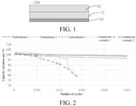
- the cycle curves of some examples are plotted in FIG. 2 .
- the DCIR test method is as follows: 1) discharging the battery at 0.2 C to a cutoff voltage of 2.5 V at normal temperature (25°C), and resting the battery for 30 minutes; charging the battery at 0.2 C to 4.2 V at normal temperature, and resting the battery for 30 minutes; discharging the battery at 0.2 C to 2.5 V at normal temperature, and calculating an initial capacity Co of the battery; and charging the battery at 0.2 C (50% Co), to adjust a state of charge (SOC) of the battery to 50% SOC; 2) resting the battery at -10°C for 12 hours, and testing the DCIR value that the battery is charged at 1 C for 30 seconds.
- SOC state of charge
- the cycle performance test method is as follows: 1) charge: at 25°C, charging the battery at 1 C constant current to 4.1 V, charging the battery at 0.5 C to 4.15 V, charging the battery at 0.2 C to 4.2 V, and resting the battery for 30 minutes; 2) discharge: discharging the battery at 1C constant current to 2.5 V, and resting the battery for 30 minutes; 3) a termination condition: these operations are repeated 500 times.
- the capacity retention rates of the batteries prepared by using the negative electrode plates of Embodiments 1 and 2 are highest, followed by those of the batteries prepared by using the negative electrode plates of Embodiments 3 to 5, but they are much higher than those of the batteries prepared by using the negative electrode plates of the comparison examples. Since the tortuosity difference of the two active coating layers in the negative electrode of the battery according to each embodiment of the present disclosure satisfies the condition of 0.5 ⁇ t 2 -t 1 ⁇ 3.2, under high rate conditions, the upper second negative electrode active coating layer can provide more hole structures, which is conducive for electrolyte infiltration, thereby being advantageous to the liquid phase transport of lithium ions.
- the first active coating layer has more compact structures, which is beneficial to maintain the solid phase transport and the electron transport of lithium ions during the cycle.
- t 2 -t 1 >3 Comparparison example 3
- the capacity retention rate of the battery is decreased.
- t 2 -t 1 ⁇ 0.5 Comparparison Examples 1 to 2
- the cycle curves of the batteries show a sudden drop, which is due to the difficulty in the liquid phase diffusion of lithium ions and thereby resulting in lithium plating.
- the negative electrode plate includes two negative electrode active material layers, and the difference between the tortuosity of the second negative electrode active material layer away from the current collector and the tortuosity of the first negative electrode active material layer adjacent to the current collector is in a range of 0.5 to 3.2, the battery prepared by using the negative electrode plate can be ensured to have a relatively low DCIR value, so as to have stable cycle performance at a high rate, thereby prolonging its service life.
Landscapes
- Chemical & Material Sciences (AREA)
- Chemical Kinetics & Catalysis (AREA)
- Electrochemistry (AREA)
- General Chemical & Material Sciences (AREA)
- Engineering & Computer Science (AREA)
- Materials Engineering (AREA)
- Manufacturing & Machinery (AREA)
- Composite Materials (AREA)
- Inorganic Chemistry (AREA)
- Battery Electrode And Active Subsutance (AREA)
- Secondary Cells (AREA)
Abstract
Description
- This application claims priority to and benefits of
Chinese Patent Application No. 202010811820.4, entitled "NEGATIVE ELECTRODE PLATE AND SECONDARY BATTERY" and filed on August 13, 2020 - The present disclosure relates to the battery field, and more specifically, to a negative electrode plate and a secondary battery.
- As economy and technology advance, industries such as portable electronic devices (mobile phones, tablets, laptops), drones, and electric vehicles, have an urgent need for energy storage components with a higher energy density and a higher power density. Currently, in lithium-ion batteries based on negative electrodes such as graphite, the negative electrode active material layer is a single coating layer. The single negative electrode active material layer after rolling has non-uniform tortuosity, with a small tortuosity at the surface layer away from a current collector. As such when the battery is charged and discharged at a high rate, the lithium ions in the negative electrode active material layer away from the current collector have a relatively low rate of liquid phase diffusion, which makes it difficult for the battery to exhibit a high capacity and resulting in rapid cycle attenuation, moreover, lithium plating is prone to occur on the surface of the negative electrode plate, which greatly affects the cycle performance and has potential safety hazards.
- The present disclosure aims to resolve at least one of the technical problems existing in the related art. In view of this, the present disclosure provides a negative electrode plate, which can improve the capacity retention rate of a battery, thereby avoiding lithium plating from occurring in the battery.
- A negative electrode plate is provided, which includes a current collector, and a first negative electrode active material layer and a second negative electrode active material layer sequentially arranged on the current collector. A tortuosity of the first negative electrode active material layer and a tortuosity of the second negative electrode active material layer satisfy: 1<t1≤5, 1<t2≤5, and 0.5<t2-t1≤3.2, where t1 represents the tortuosity of the first negative electrode active material layer, t2 represents the tortuosity of the second negative electrode active material layer, and t2-t1 represents a difference between the tortuosity of the second negative electrode active material layer and the tortuosity of the first negative electrode active material layer.
- Therefore, by controlling the tortuosity of the upper negative electrode active material layer and the tortuosity of lower negative electrode active material layer to satisfy the foregoing conditions, in the case of the same surface density and compacted density, the second active coating layer with the high tortuosity can provide more hole structures, which is conducive for electrolyte infiltration during a process of battery cycle, this improves the lithium intercalation capacity, thereby preventing lithium plating from occurring on the surface of the negative electrode plate. In addition, the first active coating layer with the small tortuosity has a relatively compact structure, which is beneficial to maintain the solid phase transport efficiency of lithium ions during the process of battery cycle. The appropriate tortuosity difference between the two layers allows the battery to have a high capacity retention rate when being cycled at a high rate, with no lithium plating phenomenon occurring.
- A secondary battery is provided, which includes the foregoing negative electrode plate. The secondary battery can maintain a high capacity when being cycled at a high rate, thereby having high cycle stability.
- Other aspects and advantages of the present disclosure will be given in the following description, some of which will become apparent from the following description or may be learned from practices of the present disclosure.
- The foregoing and/or additional aspects and advantages of the present disclosure will become apparent and comprehensible in the description of the embodiments made with reference to the following accompanying drawings.
-
FIG. 1 is a schematic structural diagram of a negative electrode plate according to an embodiment of the present disclosure; and -
FIG. 2 is normal temperature cycle curves of the batteries prepared by using the negative electrode plates of the embodiments of the present disclosure and the negative electrode plates of the comparison examples. - Embodiments of the present disclosure are described in detail below, and examples of the embodiments are shown in accompanying drawings, where the same or similar elements or the elements having same or similar functions are denoted by the same or similar reference numerals throughout the description. The embodiments described below with reference to the accompanying drawings are exemplary and used only for explaining the present disclosure, and should not be construed as a limitation on the present disclosure.
- In the description of the present disclosure, it should be understood that orientation or position relationships indicated by the terms such as "center", "upper", "under", "front", "behind", "left", "right", "vertical", "horizontal", "top", "bottom", "inside", and "outside" are based on orientation or position relationships shown in the accompanying drawings, and are used only for ease and brevity of illustration and description, rather than indicating or implying that the mentioned apparatus or component needs to have a particular orientation or needs to be constructed and operated in a particular orientation. Therefore, such terms should not be construed as limiting of the present disclosure.
- In addition, terms "first" and "second" are used merely for the purpose of description, and shall not be construed as indicating or implying relative importance or implying a quantity of indicated technical features. Therefore, a feature limited by "first" or "second" may explicitly or implicitly include one or more of the features. In the description of the present disclosure, unless otherwise stated, "a plurality of" means two or more than two.
- The following describes the embodiments of the present disclosure with reference to the accompanying drawings.
- Referring to
FIG. 1 , anegative electrode plate 100 according to an embodiment of the present disclosure includes acurrent collector 10, and a first negative electrodeactive material layer 11 and a second negative electrodeactive material layer 12 sequentially arranged on the current collector. A tortuosity of the first negative electrodeactive material layer 11 and a tortuosity of the second negative electrodeactive material layer 12 satisfy: 1<t1≤5, 1<t2≤5, and 0.5<t2-t1≤3; where t1 represents the tortuosity of the first negative electrodeactive material layer 11, t2 represents the tortuosity of the second negative electrodeactive material layer 12, and t2-t1 represents a difference between the tortuosity of the second negative electrodeactive material layer 12 and the tortuosity of the first negative electrodeactive material layer 11. - In the present disclosure, the tortuosity represents a ratio of a transport path of lithium ions in a negative electrode active material layer to a layer thickness. In the negative electrode plate, the tortuosity t2 of the second negative electrode
active material layer 12 away from thecurrent collector 10 is greater than the tortuosity t1 of the first negative electrodeactive material layer 11 adjacent to the current collector. In the case of the same surface density and compacted density, the second negative electrodeactive material layer 12 with the high tortuosity can provide more hole structures, which is conducive for electrolyte infiltration during a process of battery cycle, this helps liquid phase transport of lithium ions, which improves the lithium insertion capacity, thereby preventing lithium plating from occurring in the interface between the negative electrode plate and the electrolyte. In addition, the firstactive coating layer 11 with the small tortuosity has a relatively compact structure, which is beneficial to maintain the solid phase transport of lithium ions during the process of battery cycle. All in all, a battery prepared by using the negative electrode plate with the two negative electrode active material layers is allowed to have more uniform lithium insertion at the negative electrode plate when being charged, so that the battery can have a relatively high capacity and energy density, and have a high capacity retention rate during the cycle, with low capacity fading. - Generally, the larger the tortuosity, the looser the coating layer, which is convenient for lithium-ion transport. However, an excessive tortuosity causes a sharp decrease in an electronic conductivity and an increase in a battery impedance. In an embodiment of the present disclosure, the tortuosity t2 of the second negative electrode
active material layer 12 and the tortuosity t1 of the first negative electrodeactive material layer 11 are controlled to be within a range of (1, 5], so that the two negative electrode active material layers can have better ionic conductivity and electrical conductivity. In addition, in the case of the same surface density and compacted density, if t1 and t2 satisfy the condition of 0.5<t2-t1≤3.2, the battery has a relatively high capacity retention rate when being cycled at a high rate, thereby having good cycle stability. If t2-t1>3.2, the lithium ions mainly react in the second negative electrode active material layer, resulting in loss of the overall capacity of the battery. If t2-t1<0.5, t2 and t1 are generally small due to the requirement for the surface density and compacted density of the negative electrode plate, so that the second negative electrode active material layer is difficult to be infiltrated, which leads to a difficulty in the liquid phase diffusion of lithium ions in the negative electrode plate, as such lithium plating is prone to occur, and the cycle curve of the battery at a high rate shows a sudden drop. Therefore, only in the case that t2-t1 is controlled within an appropriate range, the battery can have a high capacity retention rate when being cycled at a high rate, and there is no lithium plating. - In an embodiment of the present disclosure, 0.5<t2-t1≤3. In another embodiment of the present disclosure, 1≤t2-t1≤3.
- Generally, the larger the D50 of an active material, the larger the tortuosity of the negative electrode active material layer. In an embodiment of the present disclosure, the first negative electrode
active material layer 11 includes a first negative electrode active material, and the second negative electrodeactive material layer 12 includes a second negative electrode active material. In addition, a D50 of the second negative electrode active material is greater than a D50 of the first negative electrode active material. The D50 of the first negative electrode active material and the D50 of the second negative electrode active material are both in a range of 8 µm to 20 µm. That is, the D50 of the negative electrode active material in the second negative electrodeactive material layer 12 away from the current collector 10 (or "adjacent to the electrolyte") is set to be large, and the D50 of the negative electrode active material in the first negative electrodeactive material layer 11 adjacent to the current collector 10 (or "away from the electrolyte") is set to be small. In this way, the second negative electrodeactive material layer 12 adjacent to the electrolyte is more fully infiltrated by the electrolyte during the process of battery cycle, which improves the lithium insertion capacity of the battery, thereby preventing the occurrence of lithium plating,thereby allows the battery to have high cycle stability, and also ensures that the two negative electrode active material layers have consistent lithium extraction/insertion rate. - The D50 of the first negative electrode active material is 8 µm to 13 µm, and the D50 of the second negative electrode active material is 13 µm to 20 µm. The difference between the D50 of the second negative electrode active material and the D50 of the first negative electrode active material is 3 µm or more, which better ensures that the tortuosity difference between the second negative electrode active material layer and the first negative electrode active material layer is within an appropriate range, thereby being more conducive to the consistency of the lithium extraction/insertion rate of the two negative electrode active material layers. For example, the D50 of the second negative electrode active material and the D50 of the first negative electrode active material may be 13 µm and 8 µm, or 15 µm and 13 µm, or 17 µm and 13 µm, respectively.
- In other embodiments of the present disclosure, the tortuosity of the first negative electrode active coating layer and the tortuosity of the second negative electrode active coating layer may be changed by means of laser etching, pore forming agent, rolling several times, or the like.
- In the present disclosure, the first negative electrode
active material layer 11 and the second negative electrodeactive material layer 12 each further includes a conductive agent and a binder. That is, the first negative electrodeactive material layer 11 includes the first negative electrode active material, the conductive agent, and the binder; and the second negative electrodeactive material layer 12 includes the second negative electrode active material, the conductive agent, and the binder. The content of the conductive agent, the binder and the negative electrode active material is not limited. A mass of the first negative electrode active material accounts for 90% to 98% of a mass of the first negative electrodeactive material layer 11, and a mass of the second negative electrode active material accounts for 90% to 98% of a mass of the second negative electrodeactive material layer 12. In this way, thenegative electrode plate 100 is allowed to have a relatively high negative electrode active material load, thereby improving the energy density of the battery. - A thickness of the first negative electrode
active material layer 11 and a thickness of the second negative electrodeactive material layer 12 are both in a range of 30 µm to 100 µm. If the thickness of each negative electrode active material layer is greater than 100 µm, the energy density of the battery is increased while the power density is decreased; and if the thickness of each negative electrode active material layer is less than 30 µm, the power density of the battery is increased while the energy density is decreased. The thickness of the first negative electrodeactive material layer 11 and the thickness of the second negative electrodeactive material layer 12 are both in a range of 40 µm to 75 µm. The thickness of the first negative electrodeactive material layer 11 may be equal to or different from the thickness of the second negative electrodeactive material layer 12. A sum of the thickness of the first negative electrodeactive material layer 11 and the thickness of the second negative electrodeactive material layer 12 is in a range of 80 µm to 150 µm. - Generally, the larger the porosity of the active material layer, the larger the tortuosity of the active material layer. However, if the porosity of the active material layer is greater than 40%, there is a great reduction in the energy density of the battery. The porosity of the first negative electrode
active material layer 11 is 20% to 30%, and the porosity of the second negative electrodeactive material layer 12 is 30% to 40%. In addition, the porosity of the second negative electrode active material layer is greater than the porosity of the first negative electrode active material layer. For example, the porosity of the first negative electrodeactive material layer 11 and the porosity of the second negative electrodeactive material layer 12 may be 20% and 30%, or 25% and 36%, or 30% and 40%, respectively. - The surface density of the first negative electrode
active material layer 11 and the surface density of the second negative electrodeactive material layer 12 are both in a range of 0.3 g/dm2 to 0.8 g/dm2. - The compacted density of the
negative electrode plate 100 is 1.45 g/cm3 to 1.70 g/cm3. - In the present disclosure, the
current collector 10 may be a material suitable for use as the current collector of the negative electrode plate, which includes but is not limited to a metal foil, an alloy foil, and a composite foil of a metal and a polymer, such as copper, nickel, stainless steel, and the like. Preferably, thecurrent collector 10 is a copper foil. Thecurrent collector 10 may undergo etching processing or coarsening processing, to form a secondary structure, which is conducive to form a close and effective contact with the first negative electrodeactive material layer 11. - The first negative electrode active material and the second negative electrode active material are independently selected from one or more of graphite, soft carbon, hard carbon, lithium titanate, a silicon-based material, and a tin-based material. That is, the first negative electrode active material and the second negative electrode active material may be the same or different in terms of material. The silicon-based material may include elemental silicon, silicon alloy, silicon oxide, a silicon-carbon composite material, and the like. The tin-based material may include elemental tin, tin oxide, tin-based alloy, and the like.
- In the present disclosure, the binder and the conductive agent in each of the first negative electrode
active material layer 11 and the second negative electrodeactive material layer 12 are not specifically limited, which may use conventional materials in the art. For example, the binder may include one or more of styrene-butadiene rubber (SBR), polyvinylidene fluoride (PVDF), polytetrafluoroethylene (PTFE), polyvinyl alcohol (PVA), polyacrylonitrile (PAN), polyimide (PI), polyacrylic acid (PAA), polyacrylate (such as polymethyl methacrylate, polymethyl acrylate, polyethyl acrylate, and the like), polyolefin (such as polypropylene, polyethylene, and the like), carboxymethyl cellulose (CMC), sodium alginate, and the like. For example, the conductive agent may include but is not limited to one or more of a branched-chain conductive agent, a one-dimensional chain/linear conductive agent, a two-dimensional sheet conductive agent, a three-dimensional spherical conductive agent, and the like. Specifically, the conductive agent may include one or more of polyacetylene, polythiophene, polypyrrole, polyaniline, carbon fiber, carbon nanotube, graphite, graphene, conductive carbon black, furnace black, mesophase carbon microbeads, and the like. The conductive carbon black may specifically include acetylene black, Ketjen black, Supper P, 350G carbon black, and the like. The graphite may include natural graphite (such as flake graphite, expanded graphite) and artificial graphite (such as KS-6 graphite, spherical graphite), and the like. - The negative electrode plate according to the first aspect of the present disclosure may be prepared by a known method in the art. For example, a preparation method of the negative electrode plate may include: coating a first negative electrode active material slurry and a second negative electrode active material slurry on a surface of the current collector; and after drying and pressing, sequentially forming the first negative electrode active material layer and the second negative electrode active material layer on the current collector.
- The methods of coating may specifically include one or a combination of more of drop coating, brush coating, spray coating, dip coating, blade coating, spin coating. The time and temperature of coating may be set according to an actual requirement. The coating operation may be carried out in a dry room or in a protective atmosphere. The first negative electrode active material slurry may include the first negative electrode active material, the conductive agent, the binder, and a solvent; and the second negative electrode active material slurry may include the second negative electrode active material, the conductive agent, the binder, and a solvent. In an embodiment of the present disclosure, the first negative electrode active material slurry and the second negative electrode active material slurry are sequentially coated using a double-layer coating die head.
- An embodiment of the present disclosure further provides a secondary battery, which includes the foregoing negative electrode plate.
- The secondary battery further includes a positive electrode plate, and a separator film and an electrolyte arranged between the positive electrode plate and the negative electrode plate.
- The positive electrode plate may be a positive electrode plate suitable for the secondary battery, which may specifically include but is not limited to one or a combination of more of a lithium iron phosphate positive electrode plate, a nickel cobalt manganese ternary positive electrode plate, a nickel cobalt aluminum ternary positive electrode plate, a lithium cobalt oxide positive electrode plate, and a lithium manganate positive electrode plate.
- The separator film may be any separator film suitable for the secondary battery, which may specifically include but is not limited to one or more of polyethylene, polypropylene, nonwoven fabric, a polyester material, and the like, and a multilayer composite film thereof. The electrolyte includes an electrolyte salt and an organic solvent. The specific types and compositions of the electrolyte salt and the organic solvent are conventional selections in the battery field, which may be selected according to an actual requirement.
- The technical solutions of the present disclosure are described below with specific embodiments.
- A negative electrode plate includes a copper foil with a thickness of 6 µm, and a first negative electrode active material layer and a second negative electrode active material layer sequentially arranged on the copper foil. A tortuosity of the first negative electrode active material layer is 3.42, and a tortuosity of the second active coating layer is 4.55. A difference between the tortuosity of the second active coating layer and the tortuosity of the first negative electrode active material layer is 1.13.
- In
Embodiment 1, a D50 of a negative electrode active material (specifically graphite) in the first negative electrode active material layer is 11 µm, and a D50 of a negative electrode active material (specifically graphite) in the second negative electrode active material layer is 17 µm. The first negative electrode active material layer has a thickness of 40 µm, and a surface density of 0.675 g/dm2. The second negative electrode active material layer has a thickness of 42 µm, and a surface density of 0.688 g/dm2. - The preparation method of the negative electrode plate includes:
- (1) A negative electrode active material (specifically graphite), a conductive agent Supper P, carboxymethyl cellulose (CMC), styrene-butadiene rubber (SBR) and water are prepared into two slurries in a mass ratio of 100:2:1.6:1.8:128. In each slurry, a solid content is 45.2%, and a viscosity of the slurry is 2300 cps. AD50 of the graphite in the first negative electrode active material slurry is 11 µm, and a D50 of the graphite in the second negative electrode active material slurry is 17 µm.
- (2) The first negative electrode active material slurry and the second negative electrode active material slurry are uniformly coated on a copper foil with a thickness of 6 µm in sequence by using a double-layer coating die head, and baked in an oven at 120°C for 15 minutes, and then after cooling, it is rolled at 2 MPa, to obtain a negative electrode plate. The negative electrode plate has a surface density of 1.363 g/dm2, and has a compacted density of 1.60 g/cm3. A sum of the thicknesses of the two active material layers is 82 µm.
- In the present disclosure, a focused ion beam-scanning electron microscope (FIB-SEM) is used to test the tortuosity of each active material layer in
Embodiment 1, and the test method is as follows: FIB slicing is performed on a test sample every 50 nm thickness, and then SEM scanning is performed, these operations are repeated several times, and three-dimensional (3D) reconstruction is performed on all the scanning results, to obtain a 3D image of the plate. Then, a professional software is used for analysis, to obtain the tortuosity. - A negative electrode plate includes a copper foil with a thickness of 6 µm, and a first negative electrode active material layer and a second negative electrode active material layer sequentially arranged on the copper foil. A tortuosity of the first negative electrode active material layer is 1.88, and a tortuosity of the second active coating layer is 4.06. A difference between the tortuosity of the second active coating layer and the tortuosity of the first negative electrode active material layer is 2.18.
- In
Embodiment 2, a D50 of a negative electrode active material (specifically graphite) in the first negative electrode active material layer is 8 µm, and a D50 of a negative electrode active material (specifically graphite) in the second negative electrode active material layer is 15 µm. - A negative electrode plate includes a copper foil with a thickness of 6 µm, and a first negative electrode active material layer and a second negative electrode active material layer sequentially arranged on the copper foil. A tortuosity of the first negative electrode active material layer is 1.75, and a tortuosity of the second active coating layer is 4.92. A difference between the tortuosity of the second active coating layer and the tortuosity of the first negative electrode active material layer is 3.17.
- In
Embodiment 3, a D50 of a negative electrode active material (specifically graphite) in the first negative electrode active material layer is 8 µm, and a D50 of a negative electrode active material (specifically graphite) in the second negative electrode active material layer is 20 µm. - A negative electrode plate includes a copper foil with a thickness of 6 µm, and a first negative electrode active material layer and a second negative electrode active material layer sequentially arranged on the copper foil. A tortuosity of the first negative electrode active material layer is 2.33, and a tortuosity of the second active coating layer is 3.02. A difference between the tortuosity of the second active coating layer and the tortuosity of the first negative electrode active material layer is 0.69.
- In Embodiment 4, a D50 of a negative electrode active material (specifically graphite) in the first negative electrode active material layer is 9 µm, and a D50 of a negative electrode active material (specifically graphite) in the second negative electrode active material layer is 11 µm.
- A negative electrode plate includes a copper foil with a thickness of 6 µm, and a first negative electrode active material layer and a second negative electrode active material layer sequentially arranged on the copper foil. A tortuosity of the first negative electrode active material layer is 1.81, and a tortuosity of the second active coating layer is 4.62. A difference between the tortuosity of the second active coating layer and the tortuosity of the first negative electrode active material layer is 2.81.
- In Embodiment 5, a D50 of a negative electrode active material (specifically graphite) in the first negative electrode active material layer is 8 µm, and a D50 of a negative electrode active material (specifically graphite) in the second negative electrode active material layer is 17 µm.
- In order to highlight the beneficial effects of the embodiments of the present disclosure, the following comparison examples 1 to 4 are provided.
- A negative electrode plate includes a copper foil with a thickness of 6 µm, and a first negative electrode active material layer and a second negative electrode active material layer sequentially arranged on the copper foil. A tortuosity of the first negative electrode active material layer is 2.97, and a tortuosity of the second active coating layer is 3.11. A difference between the tortuosity of the second active coating layer and the tortuosity of the first negative electrode active material layer is 0.14.
- In Comparison example 1, a D50 of a negative electrode active material (specifically graphite) in the first negative electrode active material layer is 14 µm, and a D50 of a negative electrode active material (specifically graphite) in the second negative electrode active material layer is 15 µm.
- A negative electrode plate includes a copper foil with a thickness of 6 µm, and a first negative electrode active material layer and a second negative electrode active material layer sequentially arranged on the copper foil. A tortuosity of the first negative electrode active material layer is 3.90, and a tortuosity of the second active coating layer is 2.01. A difference between the tortuosity of the second active coating layer and the tortuosity of the first negative electrode active material layer is -1.89.
- In Comparison example 2, a D50 of a negative electrode active material (specifically graphite) in the first negative electrode active material layer is 14 µm, and a D50 of a negative electrode active material (specifically graphite) in the second negative electrode active material layer is 9 µm.
- A negative electrode plate includes a copper foil with a thickness of 6 µm, and a first negative electrode active material layer and a second negative electrode active material layer sequentially arranged on the copper foil. A tortuosity of the first negative electrode active material layer is 1.18, and a tortuosity of the second active coating layer is 5.22. A difference between the tortuosity of the second active coating layer and the tortuosity of the first negative electrode active material layer is 4.04.
- A negative electrode plate includes a copper foil with a thickness of 6 µm, and a negative electrode active material layer with a thickness of 82 µm arranged on the copper foil. A D50 of the graphite in the active coating layer is 15 µm. A tortuosity of the negative electrode active material layer is 3.06, and a tortuosity of the surface layer is slightly smaller.
- In order to support the beneficial effects brought by the technical solutions of the embodiments of the present disclosure, the negative electrode plates in the foregoing examples are prepared into corresponding batteries using the following method: in a vacuum glove box, the positive electrode plate, the separator film and the negative electrode plate are stacked in sequence, to obtain a naked battery core; then the battery core is sleeved into a case; after baking and drying, a special electrolyte for the ternary battery is injected, welding and sealing are performed; and the battery is finally obtained through processes such as high temperature aging, formation, aging, and the like.
- A direct current internal resistance (DCIR) test and a cycle performance test are performed on each battery prepared by using the negative electrode plate according to each of the foregoing embodiments and examples. The results of the DCIR test are summarized in Table 1, the results of the cycle performance test are summarized in Table 1, and the cycle curves of some examples are plotted in
FIG. 2 . - The DCIR test method is as follows: 1) discharging the battery at 0.2 C to a cutoff voltage of 2.5 V at normal temperature (25°C), and resting the battery for 30 minutes; charging the battery at 0.2 C to 4.2 V at normal temperature, and resting the battery for 30 minutes; discharging the battery at 0.2 C to 2.5 V at normal temperature, and calculating an initial capacity Co of the battery; and charging the battery at 0.2 C (50% Co), to adjust a state of charge (SOC) of the battery to 50% SOC; 2) resting the battery at -10°C for 12 hours, and testing the DCIR value that the battery is charged at 1 C for 30 seconds.
- The cycle performance test method is as follows: 1) charge: at 25°C, charging the battery at 1 C constant current to 4.1 V, charging the battery at 0.5 C to 4.15 V, charging the battery at 0.2 C to 4.2 V, and resting the battery for 30 minutes; 2) discharge: discharging the battery at 1C constant current to 2.5 V, and resting the battery for 30 minutes; 3) a termination condition: these operations are repeated 500 times.
Table 1 Summary of electrochemical performances of batteries prepared by using the negative electrode plate of each example No. -10°C 50% SOC charge DCIR (mΩ) Capacity retention rate after 500 cycles at a room temperature (%) Embodiment 13.128 98.2 Embodiment 23.142 98.0 Embodiment 33.201 96.9 Embodiment 4 3.177 97.3 Embodiment 5 3.160 97.8 Comparison example 1 4.022 41.2 Comparison example 2 4.123 45.3 Comparison example 3 3.985 60.0 Comparison example 4 3.878 48.1 - It can be seen from Table 1 that the DCIR values of the batteries prepared by using the negative electrode plates according to the embodiments of the present disclosure are much lower than those of the comparison examples, which indicates that the batteries according to the embodiments of the present disclosures have better power performance.
- As can be seen from
FIG. 2 and Table 1, the capacity retention rates of the batteries prepared by using the negative electrode plates ofEmbodiments Embodiments 3 to 5, but they are much higher than those of the batteries prepared by using the negative electrode plates of the comparison examples. Since the tortuosity difference of the two active coating layers in the negative electrode of the battery according to each embodiment of the present disclosure satisfies the condition of 0.5≤t2-t1≤3.2, under high rate conditions, the upper second negative electrode active coating layer can provide more hole structures, which is conducive for electrolyte infiltration, thereby being advantageous to the liquid phase transport of lithium ions. In addition, the first active coating layer has more compact structures, which is beneficial to maintain the solid phase transport and the electron transport of lithium ions during the cycle. When t2-t1>3 (Comparison example 3), the capacity retention rate of the battery is decreased. The reason is that the lithium ions mainly react in the second negative electrode active material layer, and the lithium ions in the first negative electrode active material layer has a poor solid phase conductivity and a high impedance, resulting in loss of the overall capacity of the battery. When t2-t1<0.5 (Comparison Examples 1 to 2), the cycle curves of the batteries show a sudden drop, which is due to the difficulty in the liquid phase diffusion of lithium ions and thereby resulting in lithium plating. - The above results show that in the case that the negative electrode plate includes two negative electrode active material layers, and the difference between the tortuosity of the second negative electrode active material layer away from the current collector and the tortuosity of the first negative electrode active material layer adjacent to the current collector is in a range of 0.5 to 3.2, the battery prepared by using the negative electrode plate can be ensured to have a relatively low DCIR value, so as to have stable cycle performance at a high rate, thereby prolonging its service life.
- Although the embodiments of the present disclosure have been shown and described, a person of ordinary skill in the art should understand that various changes, modifications, replacements and variations may be made to the embodiments without departing from the principles and spirit of the present disclosure, and the scope of the present disclosure is as defined by the appended claims and their equivalents.
Claims (10)
- A negative electrode plate, comprising a current collector, and a first negative electrode active material layer and a second negative electrode active material layer sequentially arranged on the current collector, a tortuosity of the first negative electrode active material layer and a tortuosity of the second negative electrode active material layer satisfying: 1<t1≤5,1<t2≤5, and 0.5≤t2-t1≤3.2;
wherein t1 represents the tortuosity of the first negative electrode active material layer, t2 represents the tortuosity of the second negative electrode active material layer, and t2-t1 represents a difference between the tortuosity of the second negative electrode active material layer and the tortuosity of the first negative electrode active material layer. - The negative electrode plate according to claim 1, wherein the first negative electrode active material layer comprises a first negative electrode active material, the second negative electrode active material layer comprises a second negative electrode active material, a D50 of the first negative electrode active material and a D50 of the second negative electrode active material are in a range of 8 µm to 20 µm, and the D50 of the second negative electrode active material is greater than the D50 of the first negative electrode active material.
- The negative electrode plate according to claim 2, wherein the D50 of the first negative electrode active material is 8 µm to 13 µm, and the D50 of the second negative electrode active material is 13 µm to 20 µm.
- The negative electrode plate according to claim 2 or 3, wherein a difference between the D50 of the second negative electrode active material and the D50 of the first negative electrode active material is 3 µm or more.
- The negative electrode plate according to claim 2, wherein a porosity of the first negative electrode active material layer is 20% to 30%, a porosity of the second negative electrode active material layer is 30% to 40%, and the porosity of the second negative electrode active material layer is greater than the porosity of the first negative electrode active material layer.
- The negative electrode plate according to any one of claims 1 to 5, wherein a thickness of the first negative electrode active material layer and a thickness of the second negative electrode active material layer are within a range of 30 µm to 100 µm.
- The negative electrode plate according to any one of claims 1 to 6, wherein a surface density of the first negative electrode active material layer and a surface density of the second negative electrode active material layer are in a range of 0.30 g/dm2 to 0.73 g/dm2.
- The positive electrode plate according to claim 5, wherein a mass of the first negative electrode active material accounts for 90% to 98% of a mass of the first negative electrode active material layer, and a mass of the second negative electrode active material accounts for 90% to 98% of a mass of the second negative electrode active material layer.
- The positive electrode plate according to claim 2, wherein the first negative electrode active material and the second negative electrode active material are independently selected from one or more of graphite, soft carbon, hard carbon, lithium titanate, a silicon-based material, and a tin-based material.
- A secondary battery, comprising the negative electrode plate according to any one of claims 1 to 9.
Applications Claiming Priority (2)
| Application Number | Priority Date | Filing Date | Title |
|---|---|---|---|
| CN202010811820.4A CN114079032B (en) | 2020-08-13 | 2020-08-13 | Negative electrode and secondary battery |
| PCT/CN2021/087568 WO2022033065A1 (en) | 2020-08-13 | 2021-04-15 | Negative electrode plate and secondary battery |
Publications (2)
| Publication Number | Publication Date |
|---|---|
| EP4199135A1 true EP4199135A1 (en) | 2023-06-21 |
| EP4199135A4 EP4199135A4 (en) | 2025-01-08 |
Family
ID=80246738
Family Applications (1)
| Application Number | Title | Priority Date | Filing Date |
|---|---|---|---|
| EP21855121.6A Pending EP4199135A4 (en) | 2020-08-13 | 2021-04-15 | NEGATIVE ELECTRODE PLATE AND SECONDARY BATTERY |
Country Status (6)
| Country | Link |
|---|---|
| US (1) | US20230307643A1 (en) |
| EP (1) | EP4199135A4 (en) |
| JP (1) | JP7595149B2 (en) |
| KR (1) | KR20230050395A (en) |
| CN (1) | CN114079032B (en) |
| WO (1) | WO2022033065A1 (en) |
Cited By (1)
| Publication number | Priority date | Publication date | Assignee | Title |
|---|---|---|---|---|
| EP4254547A4 (en) * | 2020-11-30 | 2025-03-19 | Ningde Amperex Technology Limited | Electrochemical device and electronic device |
Families Citing this family (17)
| Publication number | Priority date | Publication date | Assignee | Title |
|---|---|---|---|---|
| JP7432608B2 (en) * | 2021-03-26 | 2024-02-16 | 寧徳新能源科技有限公司 | Positive electrode piece, electrochemical device and electronic device including the positive electrode piece |
| CN114709367B (en) * | 2022-04-07 | 2024-05-28 | 珠海冠宇电池股份有限公司 | Negative electrode sheet, lithium ion battery and method for preparing negative electrode sheet |
| CN114843455B (en) * | 2022-06-01 | 2024-03-15 | 湖北亿纬动力有限公司 | Lithium-ion battery negative electrode sheet and preparation method thereof and lithium-ion battery |
| CN118120087B (en) * | 2022-06-01 | 2026-02-10 | 宁德时代新能源科技股份有限公司 | Secondary batteries, battery modules, battery packs and electrical devices |
| CN114899354B (en) * | 2022-06-10 | 2024-02-02 | 惠州市豪鹏科技有限公司 | Multilayer negative plate, preparation method thereof and secondary battery |
| CN114927639B (en) * | 2022-06-16 | 2023-08-15 | 欣旺达电动汽车电池有限公司 | Negative electrode plate, preparation method thereof and secondary battery |
| CN115249793A (en) * | 2022-08-31 | 2022-10-28 | 欣旺达电动汽车电池有限公司 | Negative pole piece, secondary battery and electrical equipment |
| CN115295758A (en) * | 2022-09-09 | 2022-11-04 | 宁波容百新能源科技股份有限公司 | Pole piece and preparation method and application thereof |
| CN118511295A (en) * | 2022-09-13 | 2024-08-16 | 宁德时代新能源科技股份有限公司 | Negative electrode sheet, method for manufacturing the same, secondary battery, and power consumption device |
| CN115939306B (en) * | 2022-09-16 | 2024-09-06 | 宁德时代新能源科技股份有限公司 | Negative electrode sheets, electrode assemblies, battery cells, batteries and electrical equipment |
| CN115295768B (en) * | 2022-09-29 | 2023-02-10 | 比亚迪股份有限公司 | A kind of positive plate and lithium ion battery |
| WO2024106063A1 (en) * | 2022-11-17 | 2024-05-23 | パナソニックIpマネジメント株式会社 | Non-aqueous electrolyte secondary battery |
| KR20240168659A (en) * | 2023-05-23 | 2024-12-02 | 에스케이온 주식회사 | Anode for secondary battery and lithium secondary battery including the same |
| CN117133861B (en) * | 2023-10-27 | 2024-06-21 | 宁德时代新能源科技股份有限公司 | Negative electrode plate, battery cell and electricity utilization device |
| CN119852533B (en) * | 2023-12-07 | 2025-10-21 | 宁德时代新能源科技股份有限公司 | Secondary batteries and electrical devices |
| KR20250091728A (en) * | 2023-12-14 | 2025-06-23 | 에스케이온 주식회사 | Anode for lithium secondary battery and lithium secondary battery including the same |
| CN118738631A (en) * | 2024-05-31 | 2024-10-01 | 宁德新能源科技有限公司 | Secondary battery and electronic device |
Family Cites Families (27)
| Publication number | Priority date | Publication date | Assignee | Title |
|---|---|---|---|---|
| JP4152279B2 (en) * | 2003-08-27 | 2008-09-17 | Jfeケミカル株式会社 | Negative electrode for lithium ion secondary battery and lithium ion secondary battery |
| JP4665931B2 (en) * | 2007-03-29 | 2011-04-06 | Tdk株式会社 | Anode and lithium ion secondary battery |
| JP5321116B2 (en) * | 2009-02-18 | 2013-10-23 | 株式会社村田製作所 | Non-aqueous electrolyte secondary battery |
| US8304145B2 (en) * | 2010-02-19 | 2012-11-06 | GM Global Technology Operations LLC | High tortuosity diffusion medium |
| JP5904373B2 (en) * | 2013-01-25 | 2016-04-13 | トヨタ自動車株式会社 | Nonaqueous electrolyte secondary battery |
| KR101560471B1 (en) * | 2013-01-25 | 2015-10-15 | 주식회사 엘지화학 | Anode for lithium secondary battery and lithium secondary battery comprising the same |
| JP2014154317A (en) * | 2013-02-07 | 2014-08-25 | Toshiba Corp | Electrode, nonaqueous electrolyte battery and battery pack |
| JP5815617B2 (en) * | 2013-08-20 | 2015-11-17 | 株式会社住化分析センター | Electrode evaluation method and manufacturing method |
| WO2016054530A1 (en) * | 2014-10-03 | 2016-04-07 | Massachusetts Institute Of Technology | Pore orientation using magnetic fields |
| KR102905980B1 (en) * | 2018-05-24 | 2025-12-31 | 24엠 테크놀로지즈, 인크. | High-energy-density composition-graded electrodes and methods for their fabrication |
| CN110867560B (en) * | 2018-08-28 | 2021-04-02 | 宁德时代新能源科技股份有限公司 | A kind of negative pole piece and secondary battery |
| CN109449447B (en) * | 2018-10-17 | 2021-01-15 | 宁德时代新能源科技股份有限公司 | Secondary battery |
| JP7394327B2 (en) * | 2019-03-27 | 2023-12-08 | パナソニックIpマネジメント株式会社 | secondary battery |
| CN110660965B (en) * | 2019-08-29 | 2021-12-17 | 孚能科技(赣州)股份有限公司 | Negative plate and preparation method thereof, lithium ion battery and preparation method and application thereof |
| CN111326710B (en) * | 2020-03-02 | 2022-07-19 | 合肥学院 | A sandwich structure electrode |
| CN111525092A (en) * | 2020-04-28 | 2020-08-11 | 惠州亿纬锂能股份有限公司 | A kind of pole piece, its preparation method and application in battery |
| JP7150788B2 (en) * | 2020-08-11 | 2022-10-11 | プライムプラネットエナジー&ソリューションズ株式会社 | Non-aqueous electrolyte secondary battery |
| US20220149340A1 (en) * | 2020-11-12 | 2022-05-12 | EnPower, Inc. | Anode having high top layer sphericity |
| US20220271279A1 (en) * | 2020-11-12 | 2022-08-25 | EnPower, Inc. | Anode having high top layer sphericity |
| EP4145564A4 (en) * | 2020-12-30 | 2024-03-13 | Contemporary Amperex Technology Co., Limited | SECONDARY BATTERY AND PRODUCTION METHOD THEREOF, BATTERY MODULE WITH SECONDARY BATTERY, BATTERY PACK AND APPARATUS |
| US20230112652A1 (en) * | 2021-09-24 | 2023-04-13 | EnPower, Inc. | Electrochemical cell having lithium metal anode and multilayered cathode |
| WO2023054098A1 (en) * | 2021-09-30 | 2023-04-06 | パナソニックIpマネジメント株式会社 | Negative electrode for secondary battery, and secondary battery |
| JPWO2023054096A1 (en) * | 2021-09-30 | 2023-04-06 | ||
| WO2023054146A1 (en) * | 2021-09-30 | 2023-04-06 | パナソニックIpマネジメント株式会社 | Secondary battery |
| JPWO2023145428A1 (en) * | 2022-01-28 | 2023-08-03 | ||
| JPWO2023162766A1 (en) * | 2022-02-28 | 2023-08-31 | ||
| US20250183275A1 (en) * | 2023-12-01 | 2025-06-05 | Sk On Co., Ltd. | Anode for lithium secondary battery and lithium secondary battery including the same |
-
2020
- 2020-08-13 CN CN202010811820.4A patent/CN114079032B/en active Active
-
2021
- 2021-04-15 WO PCT/CN2021/087568 patent/WO2022033065A1/en not_active Ceased
- 2021-04-15 JP JP2023510320A patent/JP7595149B2/en active Active
- 2021-04-15 KR KR1020237008245A patent/KR20230050395A/en active Pending
- 2021-04-15 US US18/041,522 patent/US20230307643A1/en active Pending
- 2021-04-15 EP EP21855121.6A patent/EP4199135A4/en active Pending
Cited By (1)
| Publication number | Priority date | Publication date | Assignee | Title |
|---|---|---|---|---|
| EP4254547A4 (en) * | 2020-11-30 | 2025-03-19 | Ningde Amperex Technology Limited | Electrochemical device and electronic device |
Also Published As
| Publication number | Publication date |
|---|---|
| JP7595149B2 (en) | 2024-12-05 |
| JP2023537139A (en) | 2023-08-30 |
| EP4199135A4 (en) | 2025-01-08 |
| KR20230050395A (en) | 2023-04-14 |
| CN114079032B (en) | 2024-06-18 |
| US20230307643A1 (en) | 2023-09-28 |
| WO2022033065A1 (en) | 2022-02-17 |
| CN114079032A (en) | 2022-02-22 |
Similar Documents
| Publication | Publication Date | Title |
|---|---|---|
| US20230307643A1 (en) | Negative electrode plate and secondary battery | |
| Jiang et al. | Preparation and characterization of silicon-based three-dimensional cellular anode for lithium ion battery | |
| CN110752345A (en) | A kind of pole piece and its preparation method and lithium ion battery | |
| EP3510654B1 (en) | Porous silicon materials and conductive polymer binder electrodes | |
| CN115020642B (en) | Preparation method of multilayer composite electrode and lithium ion battery with multilayer composite electrode | |
| CN113228342A (en) | Negative pole piece, electrochemical device comprising same and electronic device | |
| CN112825354A (en) | Lithium negative electrode, preparation method thereof and lithium secondary battery | |
| JP7807137B2 (en) | Negative electrode and secondary battery including the same | |
| CN112151755A (en) | Positive plate and battery | |
| CN105655147A (en) | Lithium-ion capacitor negative electrode unit and preparation method thereof, and lithium-ion capacitor | |
| CN114050233A (en) | Negative pole piece and battery | |
| CN115377353A (en) | Negative plate and battery using same | |
| CN116093257A (en) | Negative electrode for lithium ion secondary battery, method for preparing same, and lithium ion secondary battery comprising same | |
| CN106898740B (en) | Graphite negative electrode material and lithium ion battery | |
| US9705135B2 (en) | Negative electrode for nonaqueous electrolyte secondary battery and nonaqueous electrolyte secondary battery | |
| CN116072854A (en) | a battery | |
| CN114204038A (en) | Current collector and application thereof | |
| CN222051814U (en) | Electrode sheet and secondary battery | |
| CN112786848A (en) | Silicon-based negative electrode material | |
| JP2024543316A (en) | Secondary batteries and electrical appliances | |
| KR20130101375A (en) | Preparation method of electrode for litium rechargeable battery | |
| CN113451547A (en) | Composite metal lithium cathode and lithium ion battery comprising same | |
| US20250201806A1 (en) | Anode for lithium secondary battery and lithium secondary battery including the same | |
| Zhang et al. | Revisiting Polytetrafluorethylene Binder for Solvent-Free Lithium-Ion Battery Anode Fabrication. Batteries 2022, 8, 57 | |
| WO2026007721A1 (en) | Negative electrode sheet, preparation method therefor, lithium-ion battery, and electrical device |
Legal Events
| Date | Code | Title | Description |
|---|---|---|---|
| STAA | Information on the status of an ep patent application or granted ep patent |
Free format text: STATUS: THE INTERNATIONAL PUBLICATION HAS BEEN MADE |
|
| PUAI | Public reference made under article 153(3) epc to a published international application that has entered the european phase |
Free format text: ORIGINAL CODE: 0009012 |
|
| STAA | Information on the status of an ep patent application or granted ep patent |
Free format text: STATUS: REQUEST FOR EXAMINATION WAS MADE |
|
| 17P | Request for examination filed |
Effective date: 20230310 |
|
| AK | Designated contracting states |
Kind code of ref document: A1 Designated state(s): AL AT BE BG CH CY CZ DE DK EE ES FI FR GB GR HR HU IE IS IT LI LT LU LV MC MK MT NL NO PL PT RO RS SE SI SK SM TR |
|
| DAV | Request for validation of the european patent (deleted) | ||
| DAX | Request for extension of the european patent (deleted) | ||
| A4 | Supplementary search report drawn up and despatched |
Effective date: 20241205 |
|
| RIC1 | Information provided on ipc code assigned before grant |
Ipc: H01M 4/36 20060101ALI20241129BHEP Ipc: H01M 10/42 20060101ALI20241129BHEP Ipc: H01M 10/052 20100101ALI20241129BHEP Ipc: H01M 4/38 20060101ALI20241129BHEP Ipc: H01M 4/13 20100101ALI20241129BHEP Ipc: H01M 4/485 20100101ALI20241129BHEP Ipc: H01M 4/134 20100101ALI20241129BHEP Ipc: H01M 4/131 20100101ALI20241129BHEP Ipc: H01M 4/133 20100101ALI20241129BHEP Ipc: H01M 4/587 20100101ALI20241129BHEP Ipc: H01M 10/0525 20100101ALI20241129BHEP Ipc: H01M 4/02 20060101AFI20241129BHEP |