EP4198419A1 - Heat exchange tube assembly, manufacturing method therefor, and refrigerator - Google Patents
Heat exchange tube assembly, manufacturing method therefor, and refrigerator Download PDFInfo
- Publication number
- EP4198419A1 EP4198419A1 EP21868542.8A EP21868542A EP4198419A1 EP 4198419 A1 EP4198419 A1 EP 4198419A1 EP 21868542 A EP21868542 A EP 21868542A EP 4198419 A1 EP4198419 A1 EP 4198419A1
- Authority
- EP
- European Patent Office
- Prior art keywords
- heat exchange
- tube
- exchange tube
- vacuum
- vacuum tube
- Prior art date
- Legal status (The legal status is an assumption and is not a legal conclusion. Google has not performed a legal analysis and makes no representation as to the accuracy of the status listed.)
- Pending
Links
Images
Classifications
-
- F—MECHANICAL ENGINEERING; LIGHTING; HEATING; WEAPONS; BLASTING
- F28—HEAT EXCHANGE IN GENERAL
- F28D—HEAT-EXCHANGE APPARATUS, NOT PROVIDED FOR IN ANOTHER SUBCLASS, IN WHICH THE HEAT-EXCHANGE MEDIA DO NOT COME INTO DIRECT CONTACT
- F28D15/00—Heat-exchange apparatus with the intermediate heat-transfer medium in closed tubes passing into or through the conduit walls ; Heat-exchange apparatus employing intermediate heat-transfer medium or bodies
- F28D15/02—Heat-exchange apparatus with the intermediate heat-transfer medium in closed tubes passing into or through the conduit walls ; Heat-exchange apparatus employing intermediate heat-transfer medium or bodies in which the medium condenses and evaporates, e.g. heat pipes
- F28D15/04—Heat-exchange apparatus with the intermediate heat-transfer medium in closed tubes passing into or through the conduit walls ; Heat-exchange apparatus employing intermediate heat-transfer medium or bodies in which the medium condenses and evaporates, e.g. heat pipes with tubes having a capillary structure
-
- F—MECHANICAL ENGINEERING; LIGHTING; HEATING; WEAPONS; BLASTING
- F25—REFRIGERATION OR COOLING; COMBINED HEATING AND REFRIGERATION SYSTEMS; HEAT PUMP SYSTEMS; MANUFACTURE OR STORAGE OF ICE; LIQUEFACTION SOLIDIFICATION OF GASES
- F25B—REFRIGERATION MACHINES, PLANTS OR SYSTEMS; COMBINED HEATING AND REFRIGERATION SYSTEMS; HEAT PUMP SYSTEMS
- F25B41/00—Fluid-circulation arrangements
- F25B41/40—Fluid line arrangements
-
- F—MECHANICAL ENGINEERING; LIGHTING; HEATING; WEAPONS; BLASTING
- F28—HEAT EXCHANGE IN GENERAL
- F28D—HEAT-EXCHANGE APPARATUS, NOT PROVIDED FOR IN ANOTHER SUBCLASS, IN WHICH THE HEAT-EXCHANGE MEDIA DO NOT COME INTO DIRECT CONTACT
- F28D15/00—Heat-exchange apparatus with the intermediate heat-transfer medium in closed tubes passing into or through the conduit walls ; Heat-exchange apparatus employing intermediate heat-transfer medium or bodies
- F28D15/02—Heat-exchange apparatus with the intermediate heat-transfer medium in closed tubes passing into or through the conduit walls ; Heat-exchange apparatus employing intermediate heat-transfer medium or bodies in which the medium condenses and evaporates, e.g. heat pipes
- F28D15/04—Heat-exchange apparatus with the intermediate heat-transfer medium in closed tubes passing into or through the conduit walls ; Heat-exchange apparatus employing intermediate heat-transfer medium or bodies in which the medium condenses and evaporates, e.g. heat pipes with tubes having a capillary structure
- F28D15/043—Heat-exchange apparatus with the intermediate heat-transfer medium in closed tubes passing into or through the conduit walls ; Heat-exchange apparatus employing intermediate heat-transfer medium or bodies in which the medium condenses and evaporates, e.g. heat pipes with tubes having a capillary structure forming loops, e.g. capillary pumped loops
-
- B—PERFORMING OPERATIONS; TRANSPORTING
- B23—MACHINE TOOLS; METAL-WORKING NOT OTHERWISE PROVIDED FOR
- B23P—METAL-WORKING NOT OTHERWISE PROVIDED FOR; COMBINED OPERATIONS; UNIVERSAL MACHINE TOOLS
- B23P15/00—Making specific metal objects by operations not covered by a single other subclass or a group in this subclass
- B23P15/26—Making specific metal objects by operations not covered by a single other subclass or a group in this subclass heat exchangers or the like
-
- F—MECHANICAL ENGINEERING; LIGHTING; HEATING; WEAPONS; BLASTING
- F25—REFRIGERATION OR COOLING; COMBINED HEATING AND REFRIGERATION SYSTEMS; HEAT PUMP SYSTEMS; MANUFACTURE OR STORAGE OF ICE; LIQUEFACTION SOLIDIFICATION OF GASES
- F25B—REFRIGERATION MACHINES, PLANTS OR SYSTEMS; COMBINED HEATING AND REFRIGERATION SYSTEMS; HEAT PUMP SYSTEMS
- F25B41/00—Fluid-circulation arrangements
- F25B41/30—Expansion means; Dispositions thereof
- F25B41/37—Capillary tubes
-
- F—MECHANICAL ENGINEERING; LIGHTING; HEATING; WEAPONS; BLASTING
- F25—REFRIGERATION OR COOLING; COMBINED HEATING AND REFRIGERATION SYSTEMS; HEAT PUMP SYSTEMS; MANUFACTURE OR STORAGE OF ICE; LIQUEFACTION SOLIDIFICATION OF GASES
- F25D—REFRIGERATORS; COLD ROOMS; ICE-BOXES; COOLING OR FREEZING APPARATUS NOT OTHERWISE PROVIDED FOR
- F25D23/00—General constructional features
- F25D23/006—General constructional features for mounting refrigerating machinery components
-
- B—PERFORMING OPERATIONS; TRANSPORTING
- B23—MACHINE TOOLS; METAL-WORKING NOT OTHERWISE PROVIDED FOR
- B23P—METAL-WORKING NOT OTHERWISE PROVIDED FOR; COMBINED OPERATIONS; UNIVERSAL MACHINE TOOLS
- B23P2700/00—Indexing scheme relating to the articles being treated, e.g. manufactured, repaired, assembled, connected or other operations covered in the subgroups
- B23P2700/09—Heat pipes
-
- F—MECHANICAL ENGINEERING; LIGHTING; HEATING; WEAPONS; BLASTING
- F25—REFRIGERATION OR COOLING; COMBINED HEATING AND REFRIGERATION SYSTEMS; HEAT PUMP SYSTEMS; MANUFACTURE OR STORAGE OF ICE; LIQUEFACTION SOLIDIFICATION OF GASES
- F25B—REFRIGERATION MACHINES, PLANTS OR SYSTEMS; COMBINED HEATING AND REFRIGERATION SYSTEMS; HEAT PUMP SYSTEMS
- F25B2400/00—Component parts or details not otherwise provided for in this subclass
- F25B2400/05—Compression system with heat exchange between particular parts of the system
- F25B2400/052—Compression system with heat exchange between particular parts of the system between the capillary tube and another part of the refrigeration cycle
-
- F—MECHANICAL ENGINEERING; LIGHTING; HEATING; WEAPONS; BLASTING
- F25—REFRIGERATION OR COOLING; COMBINED HEATING AND REFRIGERATION SYSTEMS; HEAT PUMP SYSTEMS; MANUFACTURE OR STORAGE OF ICE; LIQUEFACTION SOLIDIFICATION OF GASES
- F25B—REFRIGERATION MACHINES, PLANTS OR SYSTEMS; COMBINED HEATING AND REFRIGERATION SYSTEMS; HEAT PUMP SYSTEMS
- F25B2400/00—Component parts or details not otherwise provided for in this subclass
- F25B2400/05—Compression system with heat exchange between particular parts of the system
- F25B2400/054—Compression system with heat exchange between particular parts of the system between the suction tube of the compressor and another part of the cycle
Definitions
- the present invention relates to the field of refrigerating devices, and in particular, to a heat exchange tube assembly, a fabrication method thereof and a refrigerator having the same.
- a capillary tube and a low-pressure gas return tube in the refrigerating system are generally brought into contact to form a heat exchange tube assembly.
- the gas return tube and the capillary tube generally have two contact arrangements: 1) external contact arrangement: for example, the capillary tube and the gas return tube are welded together side by side, or the capillary tube and the gas return tube are fastened together side by side by aluminum foil, or the capillary tube is wound around a periphery of the gas return tube. 2) Internal accommodation arrangement: the capillary tube is inserted through the gas return tube.
- peripheries of the capillary tube and the gas return tube are generally and additionally sleeved with a soft sleeve to separate the capillary tube and the gas return tube from a heat insulation layer; however, the soft sleeve does not have a heat insulation effect, and heat on the capillary tube and the gas return tube is directly transferred through the heat insulation layer; since the capillary tube and the gas return tube are close to a refrigerating compartment, and temperature differences between temperatures of the capillary tube and the gas return tube and a temperature in the refrigerating compartment are large, a heat load in the refrigerating compartment is large, and an influence on a heat load of the refrigerator is large; meanwhile, in order to completely exchange heat between the capillary tube and the gas return tube, the capillary tube and the gas return tube are required to be long, thus increasing a cost.
- the capillary tube directly exchanges heat with a cooling medium in the gas return tube, resulting in a good heat exchange effect, since the capillary tube is located in the cooling medium, turbulent flow may be generated in the cooling medium, thus increasing a noise generated when a compressor works.
- An object of the present invention is to provide a heat exchange tube assembly, a fabrication method thereof and a refrigerator having the same.
- a heat exchange tube assembly comprising a heat exchange tube group, the heat exchange tube group comprising a capillary tube and a gas return tube which come into contact with each other, the heat exchange tube assembly further comprises a vacuum tube with which a periphery of the heat exchange tube group is sleeved.
- the heat exchange tube assembly further comprising a getter and/or a drying agent provided in the vacuum tube.
- the heat exchange tube assembly further comprising a support for fixing the heat exchange tube group in the vacuum tube.
- the support comprises a support sleeve with which the periphery of the heat exchange tube group is sleeved and a plurality of support sheets located on a side of the support sleeve facing an inner wall of the vacuum tube.
- a section of the support sleeve is circular, and an outer diameter of the support sleeve is less than an inner diameter of the vacuum tube.
- At least two supports are provided and distributed in the vacuum tube at intervals along an axial direction of the vacuum tube.
- the gas return tube and the capillary tube are arranged side by side.
- the present invention also provides a fabrication method of a heat exchange tube assembly, comprising the following steps:
- the fabrication method further comprises the following step: placing a getter and/or a drying agent in the vacuum tube.
- the fabrication method further comprises the following step: sleeving a periphery of the heat exchange tube group with a support or placing the support in the vacuum tube.
- the vacuumizing the vacuum tube and closing an opening of the vacuum tube specifically comprises:
- a heating temperature of the vacuum tube is not lower than 70°C; and the preset vacuum degree is 1pa.
- the present invention also provides a refrigerator, comprising the above heat exchange tube assembly; or a heat exchange tube assembly fabricated using the above fabrication method of a heat exchange tube assembly.
- the present invention has the following beneficial effects: in the heat exchange tube assembly according to the present invention, by sleeving the periphery of the heat exchange tube group with the vacuum tube having a heat preservation and insulation performance, heat transfer paths, such as heat conduction, heat convection, or the like, can be eliminated, and only heat radiation is left; that is, the vacuum tube can greatly improve a heat insulation effect of the heat exchange tube assembly, thus reducing an influence of the heat exchange tube assembly on a temperature in a refrigerating compartment, and reducing a heat load of the refrigerator; meanwhile, the heat transfer paths, such as heat conduction, heat convection, or the like, are eliminated, such that the capillary tube and the gas return tube can be subjected to sufficient heat exchange, thereby reducing lengths of the capillary tube and the gas return tube to achieve a purpose of saving a cost.
- heat transfer paths such as heat conduction, heat convection, or the like
- FIGS. 1 to 3 show preferred embodiments of the present invention. It should be noted that these embodiments have no limitations on the present invention, and equivalent transformations or replacement of function, method or structure made by persons skilled in the art according to these embodiments fall within the protection scope of the present invention.
- the present invention provides a heat exchange tube assembly 100, including a heat exchange tube group 1 and a vacuum tube 2 with which a periphery of the heat exchange tube group 1 is sleeved, the vacuum tube 2 having a heat preservation and insulation effect.
- the heat exchange tube group 1 includes a capillary tube 11 and a gas return tube 12 which come into contact with each other; in an operation process of a refrigerating system with the heat exchange tube assembly 100, refrigerant liquid in the capillary tube 11 and the gas return tube 12 flow oppositely, and the capillary tube 11 exchanges heat with the gas return tube 12 during throttling, such that the liquid entering an evaporator is supercooled, harmful flash gas possibly generated during throttling is reduced, a specific volume of the flash gas in a refrigerant is reduced, and density and a throttling amount of the liquid refrigerant are increased, thereby increasing a unit refrigerating amount to a certain extent, that is, improving a refrigerating efficiency of the refrigerating system; when the capillary tube 11 is supercooled, low-pressure steam in the gas return tube 12 is also superheated, thus avoiding that a liquid impact accident of a compressor is caused due to over humid steam possibly existing in return gas entering the compressor.
- the capillary tube 11 and the gas return tube 12 are arranged side by side, but the present invention is not limited thereto; it may be understood that, in other embodiments, the capillary tube 11 may be spirally wound around a periphery of the gas return tube 12.
- the capillary tube 11 and the gas return tube 12 are welded together by solder, such that connection is stable and a cost is low.
- the capillary tube 11 and the gas return tube 12 may be fixed together side by side by winding aluminum foil.
- heat transfer paths such as heat conduction, heat convection, or the like, can be eliminated, and only heat radiation is left; that is, the vacuum tube 2 can greatly improve a heat insulation effect of the heat exchange tube assembly 100, thus reducing an influence of the heat exchange tube assembly 100 on a temperature in a refrigerating compartment, and reducing a heat load of a refrigerator; meanwhile, the heat transfer paths, such as heat conduction, heat convection, or the like, are eliminated, such that the capillary tube 11 and the gas return tube 12 can be subjected to sufficient heat exchange, thereby reducing lengths of the capillary tube 11 and the gas return tube 12 to achieve a purpose of saving the cost.
- the vacuum tube 2 is in a closed state, and a vacuum degree in the vacuum tube 2 is less than 1pa, thus guaranteeing the heat preservation and insulation performance of the vacuum tube 2.
- end openings 21 are provided at two opposite ends of the vacuum tube 2 along an axial direction of the vacuum tube 2, and after the heat exchange tube group 1 passes through the vacuum tube 2 from the end openings 21, the end openings 21 are closed by welding with solder. It may be appreciated that after the heat exchange tube group 1 passes through the vacuum tube 2, pipes for connecting the heat exchange tube group 1 with other components in the refrigerating system extend from the end openings 21.
- the vacuum tube 2 is further provided with a vacuumizing opening 22 for vacuumizing, and after the end opening 21 is closed, the vacuumizing opening 22 is connected to a vacuum pump to vacuumize the vacuum tube 2, and after the vacuum degree of the vacuum tube 2 reaches a preset vacuum degree, the vacuum pump is stopped and the vacuumizing opening 22 is closed.
- the vacuumizing opening 22 may be closed by welding with solder, or a one-way valve may be mounted at the vacuumizing opening 22, and the vacuumizing opening 22 is closed by the one-way valve, such that the vacuum tube 2 is in the closed state.
- the heat exchange tube assembly 100 further includes a getter 3 provided in the vacuum tube 2 for absorbing gas leaked into the vacuum tube 2, so as to avoid that the gas leaked into the vacuum tube 2 affects the vacuum degree in the vacuum tube 2 after a long time, that is, to keep the vacuum degree in the vacuum tube 2, thereby keeping the heat preservation and insulation performance of the vacuum tube 2.
- a getter 3 provided in the vacuum tube 2 for absorbing gas leaked into the vacuum tube 2, so as to avoid that the gas leaked into the vacuum tube 2 affects the vacuum degree in the vacuum tube 2 after a long time, that is, to keep the vacuum degree in the vacuum tube 2, thereby keeping the heat preservation and insulation performance of the vacuum tube 2.
- the getter 3 is made of a barium-lithium alloy material with a good gas absorbing effect; certainly, the present invention is not limited thereto.
- the heat exchange tube assembly 100 further includes a drying agent 4 provided inside the vacuum tube 2 to maintain dryness inside the vacuum tube 2, which is beneficial to keeping the vacuum degree in the vacuum tube 2, thereby keeping the heat preservation and insulation performance of the vacuum tube 2.
- the drying agent 4 is made of calcium oxide, and certainly, the present invention is not limited thereto.
- getter 3 and/or the drying agent 4 are/is placed in the vacuum tube 2 before the end opening 21 is closed.
- the heat exchange tube assembly 100 further includes a support 5 for fixing the heat exchange tube group 1 in the vacuum tube 2, and the support 5 is supported between the heat exchange tube group 1 and an inner wall of the vacuum tube 2, so as to prevent the heat exchange tube group 1 from contacting the inner wall of the vacuum tube 2, thereby preventing solid phase heat conduction caused by contact between the heat exchange tube group 1 and the inner wall of the vacuum tube 2, further improving the heat insulation effect of the heat exchange tube assembly 100, and enabling sufficient heat exchange to be performed between the capillary tube 11 and the gas return tube 12.
- the support 5 includes a support sleeve 51 with which the periphery of the heat exchange tube group 1 is sleeved, and a plurality of support sheets 52 located on a side of the support sleeve 51 facing the inner wall of the vacuum tube 2, and after the heat exchange tube group 1 is fixed in the vacuum tube 2 by the support 5, one end of each of the plurality of support sheets 52 apart from the support sleeve 51 abuts against the inner wall of the vacuum tube 2 to fix the heat exchange tube group 1, and a gap is formed between the heat exchange tube group 1 and the inner wall of the vacuum tube 2; that is, the heat exchange tube group 1 and the inner wall of the vacuum tube 2 are in a non-contact state.
- the present invention is not limited thereto; it may be understood that all structures of the support 5 which can fix the heat exchange tube group 1 in the vacuum tube 2 and allow the gap to be formed between the heat exchange tube group 1 and the inner wall of the vacuum tube 2 are within the protection scope of the present invention.
- the support sleeve 51 is cylindrical, and an inner diameter of the support sleeve 51 is the same as a longest diameter of the heat exchange tube group 1, such that the heat exchange tube group 1 can be stably fixed in the support sleeve 51 without shaking after the heat exchange tube group 1 is sleeved with the support sleeve 51.
- an outer diameter of the support sleeve 51 is less than an inner diameter of the vacuum tube 2, such that the support sleeve 51 can be clamped into the vacuum tube 2 easily.
- At least two supports 5 are provided and distributed in the vacuum tube 2 at intervals along the axial direction of the vacuum tube 2, so as to fix the heat exchange tube group 1 in a segmented manner, thereby further reducing solid-phase heat conduction and reducing the cost.
- the present invention further provides a fabrication method of a heat exchange tube assembly 100, including the following steps:
- S1 specifically includes: welding the capillary tube 11 and the gas return tube 12 together side by side by solder to form the heat exchange tube group 1.
- the capillary tube 11 comes into contact with the gas return tube 12, such that when a refrigerating system with the heat exchange tube assembly 100 runs, the capillary tube 11 and the gas return tube 12 can exchange heat, and liquid entering an evaporator is supercooled, thereby increasing a unit refrigerating amount, that is, improving a refrigerating efficiency of the refrigerating system; meanwhile, low-pressure steam in the gas return tube 12 is also superheated, thus avoiding that a liquid impact accident of a compressor is caused due to over humid steam possibly existing in return gas entering the compressor.
- the fabrication method further includes the following steps: sleeving a periphery of the heat exchange tube group 1 with a support 5 or placing the support 5 in the vacuum tube 2; that is, sleeving the periphery of the heat exchange tube group 1 with the support 5, and then mounting the heat exchange tube group 1 sleeved with the support 5 in the vacuum tube 2, or pre-placing the support 5 in the vacuum tube 2, and then passing the heat exchange tube group 1 through the support 5, such that on the one hand, the support 5 fixes the heat exchange tube group 1 in the vacuum tube 2; on the other hand, after the heat exchange tube group 1 is mounted in the vacuum tube 2, the support 5 can prevent the heat exchange tube group 1 from contacting an inner wall of the vacuum tube 2, thereby preventing solid phase heat conduction caused by contact between the heat exchange tube group 1 and the inner wall of the vacuum tube 2, further improving the heat insulation effect of the heat exchange tube assembly 100, and enabling sufficient heat exchange to be performed between the capillary tube 11 and the gas return tube 12.
- the fabrication method further includes the following step: placing a getter 3 and/or a drying agent 4 in the vacuum tube 2.
- the getter 3 and/or the drying agent 4 are/is placed into the vacuum tube 2 from an end opening 21 at the other end.
- step S3 specifically includes:
- a heating temperature of the vacuum tube 2 in S33 is not lower than 70°C, and further, the heating temperature of the vacuum tube 2 is not lower than 100°C, such that moisture/gas absorbed by the vacuum tube 2 and/or the capillary tube 11 and/or the gas return tube 12 is changed into gas, which is beneficial to subsequently maintaining the vacuum degree in the vacuum tube 2.
- the preset vacuum degree in S33 is 1pa, so as to guarantee a final heat preservation and insulation performance of the vacuum tube 2.
- S34 includes: closing the vacuumizing opening 22 by welding with solder; or mounting a one-way valve at the vacuumizing opening 22, and closing the vacuumizing opening 22 by the one-way valve, such that the vacuum tube 2 is in a closed state.
- the present invention further provides a refrigerator, including a heat exchange tube assembly 100, wherein a structure or a fabrication method of the heat exchange tube assembly 100 is described above, and is not repeated herein.
- the heat exchange tube assembly 100 by sleeving the periphery of the heat exchange tube group 1 with the vacuum tube 2 having the heat preservation and insulation performance, heat transfer paths, such as heat conduction, heat convection, or the like, can be eliminated, and only heat radiation is left; that is, the vacuum tube 2 can greatly improve the heat insulation effect of the heat exchange tube assembly 100, thus reducing an influence of the heat exchange tube assembly 100 on the temperature in the refrigerating compartment, and reducing a heat load of the refrigerator; meanwhile, the heat transfer paths, such as heat conduction, heat convection, or the like, are eliminated, such that the capillary tube 11 and the gas return tube 12 can be subjected to sufficient heat exchange, thereby reducing lengths of the capillary tube 11 and the gas return tube 12 to achieve a purpose of saving the cost.
- heat transfer paths such as heat conduction, heat convection, or the like
Landscapes
- Engineering & Computer Science (AREA)
- Mechanical Engineering (AREA)
- Physics & Mathematics (AREA)
- Thermal Sciences (AREA)
- General Engineering & Computer Science (AREA)
- Life Sciences & Earth Sciences (AREA)
- Sustainable Development (AREA)
- Chemical & Material Sciences (AREA)
- Combustion & Propulsion (AREA)
- Thermal Insulation (AREA)
Abstract
Description
- The present invention relates to the field of refrigerating devices, and in particular, to a heat exchange tube assembly, a fabrication method thereof and a refrigerator having the same.
- In an existing refrigerator, in order to improve a refrigerating efficiency of a refrigerating system, a capillary tube and a low-pressure gas return tube in the refrigerating system are generally brought into contact to form a heat exchange tube assembly. The gas return tube and the capillary tube generally have two contact arrangements: 1) external contact arrangement: for example, the capillary tube and the gas return tube are welded together side by side, or the capillary tube and the gas return tube are fastened together side by side by aluminum foil, or the capillary tube is wound around a periphery of the gas return tube. 2) Internal accommodation arrangement: the capillary tube is inserted through the gas return tube.
- For the external contact arrangement, peripheries of the capillary tube and the gas return tube are generally and additionally sleeved with a soft sleeve to separate the capillary tube and the gas return tube from a heat insulation layer; however, the soft sleeve does not have a heat insulation effect, and heat on the capillary tube and the gas return tube is directly transferred through the heat insulation layer; since the capillary tube and the gas return tube are close to a refrigerating compartment, and temperature differences between temperatures of the capillary tube and the gas return tube and a temperature in the refrigerating compartment are large, a heat load in the refrigerating compartment is large, and an influence on a heat load of the refrigerator is large; meanwhile, in order to completely exchange heat between the capillary tube and the gas return tube, the capillary tube and the gas return tube are required to be long, thus increasing a cost.
- For the internal accommodation arrangement, although the capillary tube directly exchanges heat with a cooling medium in the gas return tube, resulting in a good heat exchange effect, since the capillary tube is located in the cooling medium, turbulent flow may be generated in the cooling medium, thus increasing a noise generated when a compressor works.
- In view of this, it is necessary to provide a new heat exchange tube assembly, a fabrication method thereof, and a refrigerator having the same, so as to solve the above problems.
- An object of the present invention is to provide a heat exchange tube assembly, a fabrication method thereof and a refrigerator having the same.
- In order to achieve the above-mentioned object of the invention, the following technical solution is adopted in the present invention: a heat exchange tube assembly, comprising a heat exchange tube group, the heat exchange tube group comprising a capillary tube and a gas return tube which come into contact with each other, the heat exchange tube assembly further comprises a vacuum tube with which a periphery of the heat exchange tube group is sleeved.
- As a further improved technical solution of the present invention, the heat exchange tube assembly further comprising a getter and/or a drying agent provided in the vacuum tube.
- As a further improved technical solution of the present invention, the heat exchange tube assembly further comprising a support for fixing the heat exchange tube group in the vacuum tube.
- As a further improved technical solution of the present invention, the support comprises a support sleeve with which the periphery of the heat exchange tube group is sleeved and a plurality of support sheets located on a side of the support sleeve facing an inner wall of the vacuum tube.
- As a further improved technical solution of the present invention, a section of the support sleeve is circular, and an outer diameter of the support sleeve is less than an inner diameter of the vacuum tube.
- As a further improved technical solution of the present invention, at least two supports are provided and distributed in the vacuum tube at intervals along an axial direction of the vacuum tube.
- As a further improved technical solution of the present invention, the gas return tube and the capillary tube are arranged side by side.
- In order to achieve the above-mentioned object of the invention, the present invention also provides a fabrication method of a heat exchange tube assembly, comprising the following steps:
- bringing a capillary tube and a gas return tube into contact with each other to form a heat exchange tube group;
- placing the heat exchange tube group in a vacuum tube; and
- vacuumizing the vacuum tube and closing an opening of the vacuum tube.
- As a further improved technical solution of the present invention, between the placing the heat exchange tube group in a vacuum tube and the vacuumizing the vacuum tube, the fabrication method further comprises the following step: placing a getter and/or a drying agent in the vacuum tube.
- As a further improved technical solution of the present invention, between the bringing a capillary tube and a gas return tube into contact with each other to form a heat exchange tube group and the placing the heat exchange tube group in a vacuum tube, the fabrication method further comprises the following step: sleeving a periphery of the heat exchange tube group with a support or placing the support in the vacuum tube.
- As a further improved technical solution of the present invention, the vacuumizing the vacuum tube and closing an opening of the vacuum tube specifically comprises:
- closing the end openings at two ends of the vacuum tube ;
- connecting a vacuumizing opening for vacuumizing on the vacuum tube to a vacuum pump;
- heating the vacuum tube and starting the vacuum pump to realize a preset vacuum degree; and
- closing the vacuumizing opening.
- As a further improved technical solution of the present invention, a heating temperature of the vacuum tube is not lower than 70°C; and the preset vacuum degree is 1pa.
- In order to achieve the above-mentioned object of the invention, the present invention also provides a refrigerator, comprising the above heat exchange tube assembly; or a heat exchange tube assembly fabricated using the above fabrication method of a heat exchange tube assembly.
- The present invention has the following beneficial effects: in the heat exchange tube assembly according to the present invention, by sleeving the periphery of the heat exchange tube group with the vacuum tube having a heat preservation and insulation performance, heat transfer paths, such as heat conduction, heat convection, or the like, can be eliminated, and only heat radiation is left; that is, the vacuum tube can greatly improve a heat insulation effect of the heat exchange tube assembly, thus reducing an influence of the heat exchange tube assembly on a temperature in a refrigerating compartment, and reducing a heat load of the refrigerator; meanwhile, the heat transfer paths, such as heat conduction, heat convection, or the like, are eliminated, such that the capillary tube and the gas return tube can be subjected to sufficient heat exchange, thereby reducing lengths of the capillary tube and the gas return tube to achieve a purpose of saving a cost.
-
-
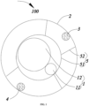
FIG. 1 is a schematic radial sectional diagram of a heat exchange tube assembly according to the present invention. -
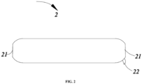
FIG. 2 is a schematic structural diagram of a vacuum tube in the heat exchange tube assembly shown inFIG. 1 . -
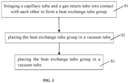
FIG. 3 is a flow chart of a fabrication method of a heat exchange tube assembly according to the present invention. - Hereinafter, the present invention will be described in detail in conjunction with embodiments shown in the accompanying drawings, and
FIGS. 1 to 3 show preferred embodiments of the present invention. It should be noted that these embodiments have no limitations on the present invention, and equivalent transformations or replacement of function, method or structure made by persons skilled in the art according to these embodiments fall within the protection scope of the present invention. - Referring to
FIG. 1 , the present invention provides a heatexchange tube assembly 100, including a heatexchange tube group 1 and avacuum tube 2 with which a periphery of the heatexchange tube group 1 is sleeved, thevacuum tube 2 having a heat preservation and insulation effect. - The heat
exchange tube group 1 includes acapillary tube 11 and agas return tube 12 which come into contact with each other; in an operation process of a refrigerating system with the heatexchange tube assembly 100, refrigerant liquid in thecapillary tube 11 and thegas return tube 12 flow oppositely, and thecapillary tube 11 exchanges heat with thegas return tube 12 during throttling, such that the liquid entering an evaporator is supercooled, harmful flash gas possibly generated during throttling is reduced, a specific volume of the flash gas in a refrigerant is reduced, and density and a throttling amount of the liquid refrigerant are increased, thereby increasing a unit refrigerating amount to a certain extent, that is, improving a refrigerating efficiency of the refrigerating system; when thecapillary tube 11 is supercooled, low-pressure steam in thegas return tube 12 is also superheated, thus avoiding that a liquid impact accident of a compressor is caused due to over humid steam possibly existing in return gas entering the compressor. - In the present embodiment, the
capillary tube 11 and thegas return tube 12 are arranged side by side, but the present invention is not limited thereto; it may be understood that, in other embodiments, thecapillary tube 11 may be spirally wound around a periphery of thegas return tube 12. - In one embodiment, the
capillary tube 11 and thegas return tube 12 are welded together by solder, such that connection is stable and a cost is low. Certainly, the present invention is not limited thereto, and in other embodiments, thecapillary tube 11 and thegas return tube 12 may be fixed together side by side by winding aluminum foil. - In the present invention, by sleeving the periphery of the heat
exchange tube group 1 with thevacuum tube 2 having a heat preservation and insulation performance, heat transfer paths, such as heat conduction, heat convection, or the like, can be eliminated, and only heat radiation is left; that is, thevacuum tube 2 can greatly improve a heat insulation effect of the heatexchange tube assembly 100, thus reducing an influence of the heatexchange tube assembly 100 on a temperature in a refrigerating compartment, and reducing a heat load of a refrigerator; meanwhile, the heat transfer paths, such as heat conduction, heat convection, or the like, are eliminated, such that thecapillary tube 11 and thegas return tube 12 can be subjected to sufficient heat exchange, thereby reducing lengths of thecapillary tube 11 and thegas return tube 12 to achieve a purpose of saving the cost. - The
vacuum tube 2 is in a closed state, and a vacuum degree in thevacuum tube 2 is less than 1pa, thus guaranteeing the heat preservation and insulation performance of thevacuum tube 2. - Referring to
FIG. 2 , specifically,end openings 21 are provided at two opposite ends of thevacuum tube 2 along an axial direction of thevacuum tube 2, and after the heatexchange tube group 1 passes through thevacuum tube 2 from theend openings 21, theend openings 21 are closed by welding with solder. It may be appreciated that after the heatexchange tube group 1 passes through thevacuum tube 2, pipes for connecting the heatexchange tube group 1 with other components in the refrigerating system extend from theend openings 21. - Meanwhile, the
vacuum tube 2 is further provided with a vacuumizingopening 22 for vacuumizing, and after the end opening 21 is closed, the vacuumizingopening 22 is connected to a vacuum pump to vacuumize thevacuum tube 2, and after the vacuum degree of thevacuum tube 2 reaches a preset vacuum degree, the vacuum pump is stopped and the vacuumizingopening 22 is closed. - Specifically, the vacuumizing
opening 22 may be closed by welding with solder, or a one-way valve may be mounted at the vacuumizingopening 22, and the vacuumizingopening 22 is closed by the one-way valve, such that thevacuum tube 2 is in the closed state. - Further, the heat
exchange tube assembly 100 further includes a getter 3 provided in thevacuum tube 2 for absorbing gas leaked into thevacuum tube 2, so as to avoid that the gas leaked into thevacuum tube 2 affects the vacuum degree in thevacuum tube 2 after a long time, that is, to keep the vacuum degree in thevacuum tube 2, thereby keeping the heat preservation and insulation performance of thevacuum tube 2. - In one embodiment, the getter 3 is made of a barium-lithium alloy material with a good gas absorbing effect; certainly, the present invention is not limited thereto.
- Further, the heat
exchange tube assembly 100 further includes adrying agent 4 provided inside thevacuum tube 2 to maintain dryness inside thevacuum tube 2, which is beneficial to keeping the vacuum degree in thevacuum tube 2, thereby keeping the heat preservation and insulation performance of thevacuum tube 2. - In one embodiment, the
drying agent 4 is made of calcium oxide, and certainly, the present invention is not limited thereto. - It may be appreciated that the getter 3 and/or the
drying agent 4 are/is placed in thevacuum tube 2 before the end opening 21 is closed. - Further, the heat
exchange tube assembly 100 further includes a support 5 for fixing the heatexchange tube group 1 in thevacuum tube 2, and the support 5 is supported between the heatexchange tube group 1 and an inner wall of thevacuum tube 2, so as to prevent the heatexchange tube group 1 from contacting the inner wall of thevacuum tube 2, thereby preventing solid phase heat conduction caused by contact between the heatexchange tube group 1 and the inner wall of thevacuum tube 2, further improving the heat insulation effect of the heatexchange tube assembly 100, and enabling sufficient heat exchange to be performed between thecapillary tube 11 and thegas return tube 12. - In one embodiment, the support 5 includes a
support sleeve 51 with which the periphery of the heatexchange tube group 1 is sleeved, and a plurality ofsupport sheets 52 located on a side of thesupport sleeve 51 facing the inner wall of thevacuum tube 2, and after the heatexchange tube group 1 is fixed in thevacuum tube 2 by the support 5, one end of each of the plurality ofsupport sheets 52 apart from thesupport sleeve 51 abuts against the inner wall of thevacuum tube 2 to fix the heatexchange tube group 1, and a gap is formed between the heatexchange tube group 1 and the inner wall of thevacuum tube 2; that is, the heatexchange tube group 1 and the inner wall of thevacuum tube 2 are in a non-contact state. - Certainly, the present invention is not limited thereto; it may be understood that all structures of the support 5 which can fix the heat
exchange tube group 1 in thevacuum tube 2 and allow the gap to be formed between the heatexchange tube group 1 and the inner wall of thevacuum tube 2 are within the protection scope of the present invention. - Specifically, the
support sleeve 51 is cylindrical, and an inner diameter of thesupport sleeve 51 is the same as a longest diameter of the heatexchange tube group 1, such that the heatexchange tube group 1 can be stably fixed in thesupport sleeve 51 without shaking after the heatexchange tube group 1 is sleeved with thesupport sleeve 51. - Further, an outer diameter of the
support sleeve 51 is less than an inner diameter of thevacuum tube 2, such that thesupport sleeve 51 can be clamped into thevacuum tube 2 easily. - Further, at least two supports 5 are provided and distributed in the
vacuum tube 2 at intervals along the axial direction of thevacuum tube 2, so as to fix the heatexchange tube group 1 in a segmented manner, thereby further reducing solid-phase heat conduction and reducing the cost. - Further, referring to
FIG. 3 , the present invention further provides a fabrication method of a heatexchange tube assembly 100, including the following steps: - S 1: bringing a
capillary tube 11 and agas return tube 12 into contact with each other to form a heatexchange tube group 1; - S2: placing the heat
exchange tube group 1 in avacuum tube 2; and - S3: vacuumizing the
vacuum tube 2 and closing an opening of thevacuum tube 2. - In one embodiment, S1 specifically includes: welding the
capillary tube 11 and thegas return tube 12 together side by side by solder to form the heatexchange tube group 1. Thecapillary tube 11 comes into contact with thegas return tube 12, such that when a refrigerating system with the heatexchange tube assembly 100 runs, thecapillary tube 11 and thegas return tube 12 can exchange heat, and liquid entering an evaporator is supercooled, thereby increasing a unit refrigerating amount, that is, improving a refrigerating efficiency of the refrigerating system; meanwhile, low-pressure steam in thegas return tube 12 is also superheated, thus avoiding that a liquid impact accident of a compressor is caused due to over humid steam possibly existing in return gas entering the compressor. - Further, between S1 and S2, the fabrication method further includes the following steps: sleeving a periphery of the heat
exchange tube group 1 with a support 5 or placing the support 5 in thevacuum tube 2; that is, sleeving the periphery of the heatexchange tube group 1 with the support 5, and then mounting the heatexchange tube group 1 sleeved with the support 5 in thevacuum tube 2, or pre-placing the support 5 in thevacuum tube 2, and then passing the heatexchange tube group 1 through the support 5, such that on the one hand, the support 5 fixes the heatexchange tube group 1 in thevacuum tube 2; on the other hand, after the heatexchange tube group 1 is mounted in thevacuum tube 2, the support 5 can prevent the heatexchange tube group 1 from contacting an inner wall of thevacuum tube 2, thereby preventing solid phase heat conduction caused by contact between the heatexchange tube group 1 and the inner wall of thevacuum tube 2, further improving the heat insulation effect of the heatexchange tube assembly 100, and enabling sufficient heat exchange to be performed between thecapillary tube 11 and thegas return tube 12. - Further, between S2 and S3, the fabrication method further includes the following step: placing a getter 3 and/or a
drying agent 4 in thevacuum tube 2. - Specifically, after an
end opening 21 at one end is closed, the getter 3 and/or thedrying agent 4 are/is placed into thevacuum tube 2 from anend opening 21 at the other end. - Further, step S3 specifically includes:
- S31: closing the
end openings 21 at the two ends of thevacuum tube 2; - S32: connecting a
vacuumizing opening 22 for vacuumizing on thevacuum tube 2 to a vacuum pump; - S33: heating the
vacuum tube 2 and starting the vacuum pump to realize a preset vacuum degree; and - S34: closing the
vacuumizing opening 22. - Specifically, a heating temperature of the
vacuum tube 2 in S33 is not lower than 70°C, and further, the heating temperature of thevacuum tube 2 is not lower than 100°C, such that moisture/gas absorbed by thevacuum tube 2 and/or thecapillary tube 11 and/or thegas return tube 12 is changed into gas, which is beneficial to subsequently maintaining the vacuum degree in thevacuum tube 2. - Specifically, the preset vacuum degree in S33 is 1pa, so as to guarantee a final heat preservation and insulation performance of the
vacuum tube 2. - Specifically, S34 includes: closing the
vacuumizing opening 22 by welding with solder; or mounting a one-way valve at thevacuumizing opening 22, and closing thevacuumizing opening 22 by the one-way valve, such that thevacuum tube 2 is in a closed state. - Further, the present invention further provides a refrigerator, including a heat
exchange tube assembly 100, wherein a structure or a fabrication method of the heatexchange tube assembly 100 is described above, and is not repeated herein. - In conclusion, in the heat
exchange tube assembly 100 according to the present invention, by sleeving the periphery of the heatexchange tube group 1 with thevacuum tube 2 having the heat preservation and insulation performance, heat transfer paths, such as heat conduction, heat convection, or the like, can be eliminated, and only heat radiation is left; that is, thevacuum tube 2 can greatly improve the heat insulation effect of the heatexchange tube assembly 100, thus reducing an influence of the heatexchange tube assembly 100 on the temperature in the refrigerating compartment, and reducing a heat load of the refrigerator; meanwhile, the heat transfer paths, such as heat conduction, heat convection, or the like, are eliminated, such that thecapillary tube 11 and thegas return tube 12 can be subjected to sufficient heat exchange, thereby reducing lengths of thecapillary tube 11 and thegas return tube 12 to achieve a purpose of saving the cost. - It should be understood that although the present specification is described based on embodiments, not every embodiment contains only one independent technical solution. Such a narration way of the present specification is only for the sake of clarity. Those skilled in the art should take the present specification as an entirety. The technical solutions in the respective embodiments may be combined properly to form other embodiments which may be understood by those skilled in the art.
- A series of the detailed descriptions set forth above is merely specific description of feasible embodiments of the present invention, and is not intended to limit the protection scope of the present invention. Equivalent embodiments or modifications made within the spirit of the present invention shall fall within the protection scope of the present invention.
Claims (13)
- A heat exchange tube assembly, comprising a heat exchange tube group, the heat exchange tube group comprising a capillary tube and a gas return tube which come into contact with each other, wherein the heat exchange tube assembly further comprises a vacuum tube with which a periphery of the heat exchange tube group is sleeved.
- The heat exchange tube assembly according to claim 1, further comprising a getter and/or a drying agent provided in the vacuum tube.
- The heat exchange tube assembly according to claim 1, further comprising a support for fixing the heat exchange tube group in the vacuum tube.
- The heat exchange tube assembly according to claim 3, wherein the support comprises a support sleeve with which the periphery of the heat exchange tube group is sleeved and a plurality of support sheets located on a side of the support sleeve facing an inner wall of the vacuum tube.
- The heat exchange tube assembly according to claim 4, wherein a section of the support sleeve is circular, and an outer diameter of the support sleeve is less than an inner diameter of the vacuum tube.
- The heat exchange tube assembly according to claim 3, wherein at least two supports are provided and distributed in the vacuum tube at intervals along an axial direction of the vacuum tube.
- The heat exchange tube assembly according to claim 1, wherein the gas return tube and the capillary tube are arranged side by side.
- A fabrication method of a heat exchange tube assembly, comprising the following steps:bringing a capillary tube and a gas return tube into contact with each other to form a heat exchange tube group;placing the heat exchange tube group in a vacuum tube; andvacuumizing the vacuum tube and closing an opening of the vacuum tube.
- The fabrication method of a heat exchange tube assembly according to claim 8, wherein between the placing the heat exchange tube group in a vacuum tube and the vacuumizing the vacuum tube, the fabrication method further comprises the following step: placing a getter and/or a drying agent in the vacuum tube.
- The fabrication method of a heat exchange tube assembly according to claim 8, wherein between the bringing a capillary tube and a gas return tube into contact with each other to form a heat exchange tube group and the placing the heat exchange tube group in a vacuum tube, the fabrication method further comprises the following step: sleeving a periphery of the heat exchange tube group with a support or placing the support in the vacuum tube.
- The fabrication method of a heat exchange tube assembly according to claim 8, wherein the vacuumizing the vacuum tube and closing an opening of the vacuum tube specifically comprises:closing the end openings at two ends of the vacuum tube ;connecting a vacuumizing opening for vacuumizing on the vacuum tube to a vacuum pump;heating the vacuum tube and starting the vacuum pump to realize a preset vacuum degree; andclosing the vacuumizing opening.
- The fabrication method of a heat exchange tube assembly according to claim 11, wherein a heating temperature of the vacuum tube is not lower than 70°C; and the preset vacuum degree is 1pa.
- A refrigerator, comprising the heat exchange tube assembly according to any one of claims 1 to 7; or a heat exchange tube assembly fabricated using the fabrication method of a heat exchange tube assembly according to any one of claims 8 to 12.
Applications Claiming Priority (2)
| Application Number | Priority Date | Filing Date | Title |
|---|---|---|---|
| CN202010967377.XA CN114184070A (en) | 2020-09-15 | 2020-09-15 | Heat exchange tube assembly, preparation method thereof and refrigerator |
| PCT/CN2021/117336 WO2022057717A1 (en) | 2020-09-15 | 2021-09-09 | Heat exchange tube assembly, manufacturing method therefor, and refrigerator |
Publications (2)
| Publication Number | Publication Date |
|---|---|
| EP4198419A1 true EP4198419A1 (en) | 2023-06-21 |
| EP4198419A4 EP4198419A4 (en) | 2024-01-17 |
Family
ID=80601197
Family Applications (1)
| Application Number | Title | Priority Date | Filing Date |
|---|---|---|---|
| EP21868542.8A Pending EP4198419A4 (en) | 2020-09-15 | 2021-09-09 | HEAT EXCHANGE TUBE ASSEMBLY, MANUFACTURING METHOD AND REFRIGERATOR |
Country Status (4)
| Country | Link |
|---|---|
| US (1) | US20230341191A1 (en) |
| EP (1) | EP4198419A4 (en) |
| CN (1) | CN114184070A (en) |
| WO (1) | WO2022057717A1 (en) |
Family Cites Families (27)
| Publication number | Priority date | Publication date | Assignee | Title |
|---|---|---|---|---|
| DE1116247B (en) * | 1957-01-26 | 1961-11-02 | Schmoele Metall R & G | Pipe element for heat exchangers, in which a jacket encloses a core pipe and at least one outer pipe of smaller cross-section resting on its circumference |
| US3397720A (en) * | 1964-10-23 | 1968-08-20 | Hitco | Multiple layer insulation for a cryogenic structure |
| US3360001A (en) * | 1965-03-17 | 1967-12-26 | James H Anderson | Vacuum jacketed pipe line and joint construction therefor |
| GB1422156A (en) * | 1972-02-09 | 1976-01-21 | Boc International Ltd | Vacuum-insulated pipeline assembly |
| DE2844223A1 (en) * | 1978-10-11 | 1980-04-24 | Gruenzweig & Hartmann Montage | Insulated pipe enclosed in ventilated tube - is held centrally by ribbed ring in tube |
| IT1136391B (en) * | 1980-05-05 | 1986-08-27 | Zanussi A Spa Industrie | DEHYDRATING AND FILTERING UNIT FOR A REFRIGERANT CIRCUIT |
| KR100281810B1 (en) * | 1998-09-12 | 2001-10-27 | 윤종용 | Refrigerant Distribution Expansion Device of Multi Air Conditioner |
| US6257282B1 (en) * | 1998-10-28 | 2001-07-10 | Mve, Inc. | Vacuum insulated pipe |
| US6666043B2 (en) * | 2002-05-07 | 2003-12-23 | Lg Electronics, Inc. | Dewfall preventing device of refrigerator |
| KR100701848B1 (en) * | 2004-07-02 | 2007-03-30 | 가부시키가이샤 만수이 | Conduit Insulation Attachment |
| CN101762049A (en) * | 2008-10-27 | 2010-06-30 | 北京环能海臣科技有限公司 | All-glass heat tube vacuum heat collecting tube |
| GB2481253A (en) * | 2010-06-18 | 2011-12-21 | Spirax Sarco Ltd | A steam pipeline |
| KR20130045722A (en) * | 2011-10-26 | 2013-05-06 | 주식회사 위닉스 | Suction pipe assembly and manufacturing method thereof |
| CN103522029A (en) * | 2013-09-29 | 2014-01-22 | 泰州乐金电子冷机有限公司 | Pipeline assembly for refrigeration, refrigerator refrigeration system and manufacturing method of pipeline assembly for refrigeration |
| CN203687400U (en) * | 2014-01-07 | 2014-07-02 | 常州市兴旺绿色能源有限公司 | High-and-middle temperature solar thermal collector |
| US9821420B2 (en) * | 2014-01-16 | 2017-11-21 | Whirlpool Corporation | Method of forming a refrigeration heat exchanger |
| CN105351684A (en) * | 2015-12-06 | 2016-02-24 | 白明军 | Pipeline system with vacuum heat preservation function |
| CN105526748A (en) * | 2016-01-29 | 2016-04-27 | 合肥美的电冰箱有限公司 | Air return heat exchange pipe component and refrigeration equipment |
| CN205593227U (en) * | 2016-04-11 | 2016-09-21 | Tcl家用电器(合肥)有限公司 | Heat exchange pipe assembly and refrigeration plant who has it |
| CN205896566U (en) * | 2016-07-21 | 2017-01-18 | 中山中舟海洋科技有限公司 | Multi -layer insulation steel pipe |
| CN206410382U (en) * | 2017-01-05 | 2017-08-15 | 合肥华凌股份有限公司 | Return-air heat exchanger tube, refrigeration system and refrigeration plant |
| CN107101392A (en) * | 2017-05-24 | 2017-08-29 | 吴闽强 | A kind of solar vacuum heat-collecting pipe |
| CN107166821A (en) * | 2017-06-16 | 2017-09-15 | 合肥华凌股份有限公司 | Heat exchanger tube, refrigeration system, the extrusion die of refrigerator and heat exchanger tube |
| CN109458775A (en) * | 2017-09-06 | 2019-03-12 | 合肥美的电冰箱有限公司 | Return-air heat exchanger tube, circulating heat exchange system and refrigerator |
| CN107387884A (en) * | 2017-09-19 | 2017-11-24 | 闵繁皓 | A kind of metal vacuum insulating tube |
| CN207599253U (en) * | 2017-12-12 | 2018-07-10 | 宁波镇洋化工发展有限公司 | A kind of vacuum heat-preserving tube |
| CN210625023U (en) * | 2019-07-01 | 2020-05-26 | 青岛海尔电冰箱有限公司 | Air return assembly and refrigerator with the air return assembly |
-
2020
- 2020-09-15 CN CN202010967377.XA patent/CN114184070A/en active Pending
-
2021
- 2021-09-09 US US18/026,591 patent/US20230341191A1/en active Pending
- 2021-09-09 WO PCT/CN2021/117336 patent/WO2022057717A1/en not_active Ceased
- 2021-09-09 EP EP21868542.8A patent/EP4198419A4/en active Pending
Also Published As
| Publication number | Publication date |
|---|---|
| CN114184070A (en) | 2022-03-15 |
| US20230341191A1 (en) | 2023-10-26 |
| EP4198419A4 (en) | 2024-01-17 |
| WO2022057717A1 (en) | 2022-03-24 |
Similar Documents
| Publication | Publication Date | Title |
|---|---|---|
| US10228169B2 (en) | Refrigerator with vacuum insulation housing a heat interchanger | |
| KR20230087432A (en) | Vacuum adiabatic body | |
| KR20230093208A (en) | Vacuum adiabatic body | |
| JP2015117778A (en) | Vacuum heat insulation pipe and vacuum heat insulation transfer tube | |
| WO2007108625A1 (en) | The cooler for transformer using generation cycle | |
| EP4198419A1 (en) | Heat exchange tube assembly, manufacturing method therefor, and refrigerator | |
| KR102204295B1 (en) | Header tank for evaporate | |
| CN111936810A (en) | Vacuum insulators and refrigerators | |
| JP3784286B2 (en) | Stirling refrigerator heat exchanger and Stirling refrigerator | |
| US7716945B2 (en) | Pressure equalization port apparatus and method for a refrigeration unit | |
| CN218348404U (en) | Low-temperature hydrogen storage device | |
| CN111936809A (en) | Vacuum insulation body and refrigerator | |
| KR20210148030A (en) | A refrigerator comprising a vacuum space | |
| KR101962146B1 (en) | A refrigerator comprising a vacuum space | |
| KR101065143B1 (en) | Solar collector | |
| JP2008267770A (en) | Capillary tube embracing heat exchanger | |
| KR102332599B1 (en) | A refrigerator comprising a vacuum space | |
| CN222398014U (en) | Cold tank assembly and water dispenser having the same | |
| RU2811009C2 (en) | Vacuum adiabatic element, refrigerator and method for manufacturing the refrigerator | |
| JP3209750U (en) | Heat exchanger | |
| JP2002340441A (en) | Heat exchanger and cooling system | |
| CN121383076A (en) | Liquid hydrogen low-evaporation efficient storage device based on heat flow escape effect | |
| JP2013032888A (en) | Heat pump and heat pump hot water supply device | |
| CN121897852A (en) | A cryogenic medium storage and transportation container | |
| JP2005030646A (en) | Ultra-low temperature freezer |
Legal Events
| Date | Code | Title | Description |
|---|---|---|---|
| STAA | Information on the status of an ep patent application or granted ep patent |
Free format text: STATUS: THE INTERNATIONAL PUBLICATION HAS BEEN MADE |
|
| PUAI | Public reference made under article 153(3) epc to a published international application that has entered the european phase |
Free format text: ORIGINAL CODE: 0009012 |
|
| STAA | Information on the status of an ep patent application or granted ep patent |
Free format text: STATUS: REQUEST FOR EXAMINATION WAS MADE |
|
| 17P | Request for examination filed |
Effective date: 20230314 |
|
| AK | Designated contracting states |
Kind code of ref document: A1 Designated state(s): AL AT BE BG CH CY CZ DE DK EE ES FI FR GB GR HR HU IE IS IT LI LT LU LV MC MK MT NL NO PL PT RO RS SE SI SK SM TR |
|
| REG | Reference to a national code |
Ref country code: DE Ref legal event code: R079 Free format text: PREVIOUS MAIN CLASS: F25B0041000000 Ipc: F25B0041400000 |
|
| DAV | Request for validation of the european patent (deleted) | ||
| DAX | Request for extension of the european patent (deleted) | ||
| A4 | Supplementary search report drawn up and despatched |
Effective date: 20231218 |
|
| RIC1 | Information provided on ipc code assigned before grant |
Ipc: F25B 41/37 20210101ALI20231212BHEP Ipc: F25B 41/40 20210101AFI20231212BHEP |
|
| GRAP | Despatch of communication of intention to grant a patent |
Free format text: ORIGINAL CODE: EPIDOSNIGR1 |
|
| STAA | Information on the status of an ep patent application or granted ep patent |
Free format text: STATUS: GRANT OF PATENT IS INTENDED |
|
| INTG | Intention to grant announced |
Effective date: 20260114 |