EP4198294B1 - Schubumkehrvorrichtung mit einer klappe einer flugzeugtriebwerksgondel mit einem element zur umlenkung von flüssigkeiten nach aussen - Google Patents
Schubumkehrvorrichtung mit einer klappe einer flugzeugtriebwerksgondel mit einem element zur umlenkung von flüssigkeiten nach aussen Download PDFInfo
- Publication number
- EP4198294B1 EP4198294B1 EP22212356.4A EP22212356A EP4198294B1 EP 4198294 B1 EP4198294 B1 EP 4198294B1 EP 22212356 A EP22212356 A EP 22212356A EP 4198294 B1 EP4198294 B1 EP 4198294B1
- Authority
- EP
- European Patent Office
- Prior art keywords
- door
- thrust reverser
- projection
- fixed structure
- downstream
- Prior art date
- Legal status (The legal status is an assumption and is not a legal conclusion. Google has not performed a legal analysis and makes no representation as to the accuracy of the status listed.)
- Active
Links
Images


Classifications
-
- F—MECHANICAL ENGINEERING; LIGHTING; HEATING; WEAPONS; BLASTING
- F02—COMBUSTION ENGINES; HOT-GAS OR COMBUSTION-PRODUCT ENGINE PLANTS
- F02K—JET-PROPULSION PLANTS
- F02K1/00—Plants characterised by the form or arrangement of the jet pipe or nozzle; Jet pipes or nozzles peculiar thereto
- F02K1/54—Nozzles having means for reversing jet thrust
- F02K1/56—Reversing jet main flow
- F02K1/60—Reversing jet main flow by blocking the rearward discharge by means of pivoted eyelids or clamshells, e.g. target-type reversers
-
- F—MECHANICAL ENGINEERING; LIGHTING; HEATING; WEAPONS; BLASTING
- F02—COMBUSTION ENGINES; HOT-GAS OR COMBUSTION-PRODUCT ENGINE PLANTS
- F02K—JET-PROPULSION PLANTS
- F02K1/00—Plants characterised by the form or arrangement of the jet pipe or nozzle; Jet pipes or nozzles peculiar thereto
- F02K1/54—Nozzles having means for reversing jet thrust
- F02K1/56—Reversing jet main flow
- F02K1/62—Reversing jet main flow by blocking the rearward discharge by means of flaps
-
- F—MECHANICAL ENGINEERING; LIGHTING; HEATING; WEAPONS; BLASTING
- F02—COMBUSTION ENGINES; HOT-GAS OR COMBUSTION-PRODUCT ENGINE PLANTS
- F02K—JET-PROPULSION PLANTS
- F02K1/00—Plants characterised by the form or arrangement of the jet pipe or nozzle; Jet pipes or nozzles peculiar thereto
- F02K1/54—Nozzles having means for reversing jet thrust
- F02K1/56—Reversing jet main flow
- F02K1/58—Reversers mounted on the inner cone or the nozzle housing or the fuselage
-
- F—MECHANICAL ENGINEERING; LIGHTING; HEATING; WEAPONS; BLASTING
- F02—COMBUSTION ENGINES; HOT-GAS OR COMBUSTION-PRODUCT ENGINE PLANTS
- F02K—JET-PROPULSION PLANTS
- F02K1/00—Plants characterised by the form or arrangement of the jet pipe or nozzle; Jet pipes or nozzles peculiar thereto
- F02K1/54—Nozzles having means for reversing jet thrust
- F02K1/64—Reversing fan flow
- F02K1/70—Reversing fan flow using thrust reverser flaps or doors mounted on the fan housing
-
- F—MECHANICAL ENGINEERING; LIGHTING; HEATING; WEAPONS; BLASTING
- F05—INDEXING SCHEMES RELATING TO ENGINES OR PUMPS IN VARIOUS SUBCLASSES OF CLASSES F01-F04
- F05D—INDEXING SCHEME FOR ASPECTS RELATING TO NON-POSITIVE-DISPLACEMENT MACHINES OR ENGINES, GAS-TURBINES OR JET-PROPULSION PLANTS
- F05D2220/00—Application
- F05D2220/30—Application in turbines
- F05D2220/32—Application in turbines in gas turbines
- F05D2220/323—Application in turbines in gas turbines for aircraft propulsion, e.g. jet engines
-
- F—MECHANICAL ENGINEERING; LIGHTING; HEATING; WEAPONS; BLASTING
- F05—INDEXING SCHEMES RELATING TO ENGINES OR PUMPS IN VARIOUS SUBCLASSES OF CLASSES F01-F04
- F05D—INDEXING SCHEME FOR ASPECTS RELATING TO NON-POSITIVE-DISPLACEMENT MACHINES OR ENGINES, GAS-TURBINES OR JET-PROPULSION PLANTS
- F05D2260/00—Function
- F05D2260/60—Fluid transfer
- F05D2260/602—Drainage
-
- Y—GENERAL TAGGING OF NEW TECHNOLOGICAL DEVELOPMENTS; GENERAL TAGGING OF CROSS-SECTIONAL TECHNOLOGIES SPANNING OVER SEVERAL SECTIONS OF THE IPC; TECHNICAL SUBJECTS COVERED BY FORMER USPC CROSS-REFERENCE ART COLLECTIONS [XRACs] AND DIGESTS
- Y02—TECHNOLOGIES OR APPLICATIONS FOR MITIGATION OR ADAPTATION AGAINST CLIMATE CHANGE
- Y02T—CLIMATE CHANGE MITIGATION TECHNOLOGIES RELATED TO TRANSPORTATION
- Y02T50/00—Aeronautics or air transport
- Y02T50/60—Efficient propulsion technologies, e.g. for aircraft
Definitions
- the present invention relates to the field of aircraft, and in particular aircraft turbomachines.
- the invention relates to door thrust reversers for turbojets.
- An aircraft is powered by one or more propulsion units, each comprising a turbojet engine housed in a tubular nacelle.
- Each propulsion unit is attached to the aircraft by a mast generally located under or on a wing or at the fuselage of the aircraft.
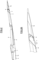
- a nacelle 1 generally has a tubular structure comprising an air inlet 2 upstream of the turbojet, a middle section 3 intended to surround a fan of the turbojet, a downstream section 4 which can house thrust reversal means and intended to surround the combustion chamber of the turbojet.
- the nacelle 1 is generally terminated by an ejection nozzle (not visible) whose outlet is located downstream of the turbojet.
- the thrust reverser means are, when the aircraft lands, intended to improve the braking capacity of the aircraft by redirecting forward at least part of the thrust generated by the turbojet engine.
- These means comprise a thrust reverser comprising one or more mobile thrust reverser elements carried by the nacelle to move between a closed position in which the thrust reverser is inactive and an open position in which the thrust reverser is active, i.e. it returns at least part of the gas flow generated by the turbojet engine in the opposite direction to the flow guided by the nacelle. In the open position, the circulating air flow can be deflected outwards and upstream of the reverser, so as to exert a counter-thrust contributing to the aircraft braking.
- the downstream section 4 of the nacelle 1 therefore comprises a fixed structure 5 and a mobile structure 6.
- the moving elements 6 of the thrust reversers can be doors.
- the fixed structure 5 thus comprises one or more housings 7 for receiving a door 6, each delimited axially by an upstream frame 7a and a downstream frame 7b and transversely by two lateral beams (not visible in the figures).
- the actuation of the thrust reverser doors 6 is generally carried out using actuators 8, visible on the figure 2 , fixed on the fixed structure 5, in particular in the upstream frame 7a, and connected on the one hand to a motor (not shown), and on the other hand to the corresponding door 6 to maneuver the latter in a direction of retraction or deployment over a stroke of the actuators between the closed position, visible on the figure 1 , and the open position, visible on the Figure 1A of the door 6.
- the door 6 In the open position, the door 6 is tilted by the actuator 8 around an axis of rotation (not shown) between said door 6 and the fixed structure 5, in particular the downstream frame 7b.
- a circumferential seal 9 is mounted on the door 6, in particular over the entire circumferential extent of said door.
- fluids from the turbojet engine area in particular between the turbojet engine cowl and the engine casing, are discharged to the outside of the nacelle via drainage holes (not shown).
- these leakage fluids flow along the turbojet engine cowl 3 and the downstream section 4, i.e. the thrust reverser.
- the leakage fluids flow along the door 6 and enter the clearance present between said door and the downstream frame 7b of the fixed structure 5 to go up along the side beams towards the upstream frame 7a.
- the area located under the upstream frame 7a includes equipment which is not sized for contact with this type of fluid, at the risk of being damaged or even causing a fire to start.
- the circumferential seal 9 is not sufficient to guarantee the sealing of the area located under the upstream frame 7a.
- the technical background includes in particular the documents US5039171 And US2002/184874 .
- the present invention therefore aims to overcome the aforementioned drawbacks.
- the objective of the invention is to prevent the passage of external fluids through the axial clearance between the door and the fixed structure, in particular the downstream frame of a thrust reverser in order to avoid any contamination of the side beams and the area located under the upstream frame of the fixed structure.
- the invention relates to a thrust reverser of an aircraft turbojet nacelle extending around a longitudinal axis and comprising a fixed structure and at least one door movable in rotation between a closed position in which said door ensures aerodynamic continuity with the fixed structure for the circulation of an air flow and an open position in which the circulating air flow is deflected outwards and upstream of the thrust reverser.
- the fixed structure comprises a downstream frame axially spaced from a downstream end edge of the door by an axial clearance parallel to the longitudinal axis.
- the thrust reverser comprises a member for diverting fluids towards the outside of the thrust reverser comprising at least one projecting part or deflector fixed on one of the door or the other of the fixed structure and extending into the axial clearance and towards one of the fixed structure or the other of the door, while leaving an axial space between a free end of said projecting part and one of the fixed structure or the other of the door.
- the protruding portion extends locally into the axial clearance. In other words, the protruding portion does not extend around the entire circumference of the end edge of the door or the upstream end of the downstream frame of the fixed structure.
- the projecting portion extends for example over an area of the circumference of the upstream end of the downstream frame of the fixed structure less than half of the total circumference of said end, preferably over an area less than one eighth of the total circumference of said end.
- the protruding part extends over an area of between 5cm and 10cm in the circumferential direction, at most over an area of 5cm.
- the projecting portion forms a deflector group.
- the fluid deflecting member associated with the door may include one or more deflector groups circumferentially spaced from each other.
- the protruding portion acts as a local, point barrier against external fluids flowing on the outer surface of the thrust reverser and is configured to change the flow direction of a flow of fluids external to the thrust reverser.
- the external fluids can be redirected outward from the thrust reverser to flow along the downstream frame of the fixed structure.
- the axial space is smaller than the axial clearance.
- the fluid diversion organ is associated with the door.
- the projecting portion or deflector extends into the axial clearance between the fixed structure and the door and does not protrude radially outside the fixed structure, so that said projecting portion is not disposed in the flow of circulation of the external fluids.
- the downstream frame includes an upstream end axially spaced from the downstream end edge of the door by the axial clearance.
- the fluid deflection member towards the outside of the thrust reverser comprises at least a first projecting part or deflector fixed on the door, in particular the downstream end edge, and extending locally in the axial clearance and towards the fixed structure, in particular the upstream end of the downstream frame, and at least a second projecting part or deflector fixed on the fixed structure, in particular the upstream end of the downstream frame, and extending locally in the axial clearance and towards the door, in particular the downstream end edge.
- the first part and the second part together form the deflector group.
- the first part carried by the door is not in contact with the downstream frame of the fixed structure and the second part carried by said downstream frame is not in contact with the end edge of the door.
- the first and second parts of the fluid deflection member form a local barrier allowing external fluids to be redirected towards the outside of the thrust reverser to run along the downstream frame of the fixed structure.
- the first protruding portion and the second protruding portion each extend locally into the axial clearance.
- the first protruding portion fixed to the door does not extend over the entire circumference of the end edge of the door and the second protruding portion fixed to the fixed structure does not extend over the entire circumference of the upstream end of the downstream frame of the fixed structure.
- the first projecting portion and the second projecting portion of the external fluid deflection member are in local and direct radial and/or circumferential contact with each other.
- the first part is in direct radial and/or circumferential support on the second part.
- Direct contact, i.e. without intermediate element, between the two parts of the flow deflection member makes it possible to improve the deflection of external fluids.
- one of the first part or the other of the second part is made of elastic material capable of being elastically deformed during an external stress and of returning to its initial shape after the external stress has stopped.
- first part carried by the door is made of elastic material and the second part carried by the fixed structure is made of a material that is more rigid than the first part
- second part carried by the fixed structure is made of elastic material and the first part carried by the door is made of a material that is more rigid than the second part
- the protruding part made of a material that is more rigid than the other part may be normal or parallel to the fixing surface.
- the protruding part made of a softer material then comes to rest on the said more rigid part.
- the deflection part of the first projecting part is substantially inclined at an angle of between 90° and 180° relative to the fixing part.
- one of the first part or the other of the second part is a seal made of a more flexible material than one of the second part or the other of the first part.
- the softer part may be made of a polymer material, such as silicone.
- the softer part could be made in the form of a metal spring blade.
- the more rigid part may be made of a rigid material, such as a metallic material, a composite material, a plastic material.
- a rigid material such as a metallic material, a composite material, a plastic material.
- rigid is meant a material that is not elastically deformable under the action of a stress exerted.
- first part and the second part may each be made of an elastic material capable of being elastically deformed upon external stress and of returning to its initial shape after the external stress has ceased.
- first projecting portion and the second projecting portion are circumferentially spaced from each other by a circumferential clearance.
- first and second parts of the fluid diverting member are angularly offset and are not in contact with each other.
- the circumferential clearance allows for manufacturing and installation tolerances of the door and fixed structure, as well as movements during flight of the aircraft, to be taken into account.
- the first projecting portion comprises a fixing portion fixed to the downstream end edge of the door and a deflection portion extending from an outer surface of the fixing portion outwardly.
- the deflection portion of the first protruding portion is substantially inclined at an angle of between 90° and 150°, for example equal to 135° relative to the fixing portion.
- the second projecting portion comprises a fixing portion fixed to the upstream end of the downstream frame of the fixed structure and a deflection portion extending from an external surface of the fixing portion outwardly.
- the deflection portion of the second protruding portion is inclined at an angle between 90° and 150°, for example equal to 90° relative to the fixing portion.
- the deflector group of the fluid deflection member associated with the door comprises a number of first projecting parts greater than or equal to two and a number of second projecting parts greater than or equal to two, the number of first projecting parts being equal to or different from the number of second projecting parts.
- first and second parts may be alternated. It is also possible to provide a succession of first parts without alternation with second parts.
- each of the first and second parts of the external fluid deflection member is made of a rigid material, such as a metallic material, a composite material, or a plastic material.
- the fluid deflection member comprises at least two deflector groups circumferentially spaced from each other.
- the thrust reverser comprises a first fluid deflection member associated with the door and comprising at least a first deflector group comprising the first projecting portion and the second projecting portion circumferentially spaced from the first projecting portion by a circumferential clearance and a second fluid deflecting member associated with said door (and comprising at least a second deflector group comprising the first projecting portion and the second projecting portion in direct local radial and/or circumferential contact with the first projecting portion.
- the thrust reverser comprises a circumferential seal fixed to the door and separate from the fluid diversion member.
- rigid we mean a material that cannot be elastically deformed under the action of a stress exerted.
- the invention relates to an aircraft turbojet nacelle comprising a door thrust reverser as described above.
- upstream and downstream are defined in relation to the direction of air flow in the turbomachine.
- axial and radial are defined relative to a longitudinal extension axis A of the thrust reverser 10.
- the thrust reverser 10 extends along a longitudinal axis A corresponding to a longitudinal axis of the nacelle (not shown).
- the thrust reverser 10 corresponds to the downstream section of the nacelle.
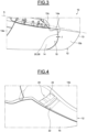
- the thrust reverser 10 comprises a fixed structure 12 and a door 14 movable in rotation about an axis transverse to the longitudinal axis, between a closed position, visible in the figure 3 , in which it ensures aerodynamic continuity with the fixed structure 12 of the inverter and with the nacelle and an open position (not visible), in which the door 14 allows the air flow to be diverted outwards and upstream of the inverter 10.
- the door 14 is pivotally mounted around an axis under the action of an actuator.
- the actuation of the door is known and will not be described further.
- the fixed structure 12 here comprises a housing 13 for receiving the door 14 delimited axially by an upstream frame 13a and a downstream frame 13b and transversely by two lateral beams 13c, only one of which is visible in the figure 3 .
- the fixed structure 12 comprises a different number of housings. door reception, for example greater than or equal to two.
- the downstream frame 13b spaced axially from a downstream end edge of the door 14 by an axial clearance J.
- the thrust reverser 10 further comprises a member 20 for diverting fluids towards the outside of the thrust reverser 10.
- the fluid deflection member 20 comprises a first part 22 secured to the door 14 and extending axially in the axial clearance J and towards the downstream frame 13b of the fixed structure 12 of the thrust reverser 10.
- An axial space (not referenced) remains between a free end of said first part 22 and an upstream end 15 of the downstream frame 13b of the fixed structure 12.
- the axial space is smaller than the axial clearance.
- the first part 22 comprises a fixing part 22a fixed on the downstream end edge 14a of said door and a deflection part 22b extending from an external surface of the fixing part 22a towards the outside.
- the deflection part 22b is here substantially inclined at an angle between 90° and 150°, for example equal to 135° relative to the fixing part 22a.
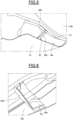
- the fluid deflection member 20 further comprises a second part 24 secured to the fixed structure 12 and extending axially in the axial clearance J from the upstream end 15 of the downstream frame 13b and towards the downstream end edge 14a of the door 14 of the thrust reverser 10.
- An axial space (not referenced) remains between a free end of said second part 24 and the downstream end edge 14a of the door 14.
- the axial space is smaller than the axial clearance.
- the second part 24 comprises a fixing part 24a fixed on the upstream end 15 of the downstream frame 13b of the fixed structure 12 and a deflection part 24b extending from an external surface of the fixing part 24a towards the outside.
- the deflection part 24b is here inclined at an angle between 90° and 150°, for example equal to 90° relative to the fixing part 24a.
- the first and second parts 22, 24 are deflectors configured to change the flow direction of a flow of fluids external to the thrust reverser.
- the first part 22 carried by the door 14 is not in contact with the downstream frame 13b of the fixed structure 12 and the second part 24 carried by said downstream frame 13b is not in contact with the end edge 14a of the door 14.
- the first and second parts 22, 24 are here circumferentially spaced from each other by a circumferential clearance.
- first and second parts 22, 24 of the fluid deflection member 20 are not in contact with each other.
- the circumferential clearance makes it possible to take into account the manufacturing and installation tolerances of the door and the fixed structure, as well as movements during the flight of the aircraft.
- the first and second projecting portions 22, 24 of the fluid deflection member 20 each extend locally in the axial clearance J.
- the first projecting portion 22 fixed to the door does not extend over the entire circumference of the end edge 14a of the door 14 and the second projecting portion 24 fixed to the fixed structure does not extend over the entire circumference of the upstream end 15 of the downstream frame 13b of the fixed structure 12.
- first and second parts 22, 24 of the fluid deflection member 20 form a local barrier allowing the external fluids to be redirected towards the outside of the thrust reverser 10 to run along the downstream frame 13b of the fixed structure 12.
- the fluid deflecting member 20 comprises a first portion 22 and a second portion 24, forming a deflector group.
- a different number of first and second portions 22, 24 of the fluid deflecting member could be provided. It could also be provided that the number of first portions 22 is different from the number of second portions 24. In the case of a plurality of first and second portions, the first and second portions may be alternated. It is also possible to provide a succession of first portions without alternation with second portions.
- the deflection organ 20 of the fluids comprises a plurality of deflector groups spaced circumferentially from one another.
- the fluid deflection member 20 comprises only one projecting part forming a deflector group and extending in the axial clearance from one of the door 14 or the other of the fixed structure 12 towards the other of the fixed structure 12 or one of the door 14.
- the first part 22 and second part 24 may be made of a rigid material, such as a metallic material, a composite material, a plastic material.
- a rigid material such as a metallic material, a composite material, a plastic material.
- rigid is meant a material that is not elastically deformable under the action of a stress exerted.
- the fluid deflection member 30 comprises a first part 32 secured to the door 14 and extending axially locally in the axial clearance J and towards the downstream frame 13b of the fixed structure 12 of the thrust reverser 10.
- An axial space (not referenced) remains between a free end of said first part 32 and the downstream frame 13b of the fixed structure 12.
- the axial space is smaller than the axial clearance.
- the first projecting portion 32 is fixed to the downstream end edge 14a of said door 14.
- the fluid deflection member 30 further comprises a second part 34 secured to the fixed structure 12, in particular fixed to the upstream end 15 of the downstream frame 13b of the fixed structure 12 and extending axially locally in the axial clearance J and towards the downstream end edge 14a of the door 14 of the thrust reverser 10.
- An axial space (not referenced) remains between a free end of said second part 34 and the downstream end edge 14a of the door 14.
- the axial space is smaller than the axial clearance.
- first and second projecting portions 32, 34 are in direct, pointwise radial contact with each other, forming a local seal between the door 14 and the downstream frame 13b.
- first portion 32 is in radial support on the second portion 34.
- the contacts between the first portion 32 and the second portion 34 are visible in detail on the figure 8 .
- the first part 32 and the second part 34 are in contact along two contact zones (not referenced).
- first projecting portion 32 fixed to the door 14 does not extend over the entire circumference of the end edge 14a of the door 14 and the second projecting portion 34 fixed to the fixed structure 12 does not extend over the entire circumference of the upstream end 15 of the downstream frame 13b of the fixed structure 12.
- first and second projecting parts 32, 34 of the fluid deflection member 30 form a local and point barrier allowing the external fluids to be redirected towards the outside of the thrust reverser 10 to run along the downstream frame 13b of the fixed structure 12.
- first and second protruding portions 32, 34 are also deflectors configured to modify the flow direction of a flow of fluids external to the thrust reverser.
- first and second projecting portions 32, 34 are in circumferential contact with each other, or even that the first and second projecting portions 32, 34 are in circumferential and radial contact with each other.
- the first part 32 may be a seal made of a more flexible material than the second part 34.
- the first part 32 is made of a polymer material, such as silicone.
- the first part 32 is made in the form of a metal spring blade.
- the first part 32 is made of an elastic material capable of being elastically deformed during an external stress and of returning to its initial shape after the external stress has stopped.
- the second part 34 may be made of a rigid material, such as a metallic material, a composite material, a plastic material.
- a rigid material such as a metallic material, a composite material, a plastic material.
- first part 32 carried by the door 14 could be more rigid than the second part 34 carried by the fixed structure 12.
- first part 32 and the second part 34 may each be made of an elastic material capable of being elastically deformed during an external stress and of returning to its initial shape after the external stress has stopped.
- the fluid deflecting member 30 includes a first portion 32 and a second portion 34 together forming a deflector group.
- first and second portions 32, 34 of the fluid deflecting member could be provided.
- Each deflector group including a first and second portion are circumferentially spaced from one another.
- first fluid deflection member 20 described with reference to Figures 4 to 6 with a second fluid deflection member 30 described with reference to Figures 7 and 8 , the first member 20 and the second member 30 being circumferentially spaced from each other.
- the thrust reverser 10 further comprises a circumferential seal 19 visible on the figure 8 extending circumferentially around the perimeter of the door 14.
- the circumferential seal 19 is distinct from the fluid deflection members 20, 30.
- the fluid deflection member 20, 30 is advantageously arranged in the axial clearance between the door 14 and the fixed structure 12 closest to the pylon or fuselage of the aircraft on which the thrust reverser 10 is intended to be mounted.
Landscapes
- Engineering & Computer Science (AREA)
- Chemical & Material Sciences (AREA)
- Combustion & Propulsion (AREA)
- Mechanical Engineering (AREA)
- General Engineering & Computer Science (AREA)
- Sealing Using Fluids, Sealing Without Contact, And Removal Of Oil (AREA)
- Structures Of Non-Positive Displacement Pumps (AREA)
- Turbine Rotor Nozzle Sealing (AREA)
Claims (12)
- Schubumkehrvorrichtung (10) für eine Flugzeugtriebwerksgondel, die sich um eine Längsachse (A) erstreckt und eine feste Struktur (12) und mindestens eine Klappe (14) umfasst, die drehbeweglich ist zwischen einer geschlossenen Position, in der die Klappe (14) eine aerodynamische Kontinuität mit der festen Struktur (12) für die Zirkulation eines Luftstroms gewährleistet, und einer offenen Position, in der der zirkulierende Luftstrom zur Außenseite und zur stromaufwärtigen Seite der Schubumkehrvorrichtung (10) abgelenkt wird, wobei die feste Struktur (12) einen stromabwärtigen Rahmen (13b) umfasst, der ein stromaufwärtiges Ende (15) umfasst, das axial von einer stromabwärtigen Endkante (14a) der Klappe (14) durch ein zur Längsachse (A) paralleles axiales Spiel (J) beabstandet ist, wobei die Schubumkehrvorrichtung mindestens ein Organ (20; 30) zum Ablenken der Fluide zur Außenseite der Schubumkehrvorrichtung (10) umfasst, das der Klappe (14) zugeordnet ist, dadurch gekennzeichnet, dass das Organ (20; 30) zum Ablenken der Fluide mindestens eine Deflektorgruppe umfasst, die mindestens einen vorspringenden Teil (22, 24; 32, 34) umfasst, der an einer der Klappe (14) oder der festen Struktur (12) befestigt ist und sich lokal von einem der stromabwärtigen Endkante (14a) der Klappe (14) oder des stromaufwärtigen Endes (15) des stromabwärtigen Rahmens (13b) in das axiale Spiel (J) und zu einem des stromaufwärtigen Endes (15) des stromabwärtigen Rahmens (13b) oder der stromabwärtigen Endkante (14a) der Klappe (14) erstreckt, während er zugleich einen axialen Raum zwischen einem freien Ende des vorspringenden Teils (22, 24; 32, 34) und einem des stromaufwärtigen Endes (15) des stromabwärtigen Rahmens (13b) der festen Struktur (12) oder der stromabwärtigen Endkante (14a) der Klappe (14) bestehen lässt.
- Schubumkehrvorrichtung (10) nach Anspruch 1, wobei die Deflektorgruppe des Organs (20; 30) zum Ablenken der Fluide zur Außenseite der Schubumkehrvorrichtung (10) mindestens einen ersten vorspringenden Teil (22; 32), der an der stromabwärtigen Endkante (14a) der Klappe (14) befestigt ist und sich lokal in das axiale Spiel (J) und zum stromaufwärtigen Ende (15) des stromabwärtigen Rahmens (13b) der festen Struktur (12) erstreckt, und mindestens einen zweiten vorspringenden Teil (24; 34) umfasst, der am stromaufwärtigen Ende (15) des stromabwärtigen Rahmens (13b) der festen Struktur (12) befestigt ist und sich lokal in das axiale Spiel (J) und zur stromabwärtigen Endkante (14a) der Klappe (14) erstreckt.
- Schubumkehrvorrichtung (10) nach Anspruch 2, wobei der erste vorspringende Teil (32) und der zweite vorspringende Teil (34) der Deflektorgruppe des Organs (30) zum Ablenken der äußeren Fluide in direktem lokalem Radial- und/oder Umfangskontakt miteinander stehen.
- Schubumkehrvorrichtung (10) nach Anspruch 3, wobei einer des ersten Teils (32) oder des zweiten Teils (34) aus elastischen Material hergestellt ist, das in der Lage ist, bei einer äußeren Beanspruchung elastisch verformt zu werden und nach Ende der äußeren Beanspruchung wieder seine ursprüngliche Form anzunehmen.
- Schubumkehrvorrichtung (10) nach Anspruch 4, wobei einer des ersten Teils (32) oder des zweiten Teils (34) eine Dichtung ist, die aus Material hergestellt ist, das weicher ist als einer des zweiten Teils oder des ersten Teils.
- Schubumkehrvorrichtung (10) nach Anspruch 2, wobei der erste vorspringende Teil (22) und der zweite vorspringende Teil (24) in Umfangsrichtung um ein Umfangsspiel voneinander beabstandet sind.
- Schubumkehrvorrichtung (10) nach Anspruch 6, wobei der erste vorspringende Teil (22) einen Befestigungsteil (22a), der an der stromabwärtigen Endkante (14a) der Klappe (14) befestigt ist, und einen Ablenkteil (22b) umfasst, der sich von einer äußeren Fläche des Befestigungsteils (22a) zur Außenseite erstreckt.
- Schubumkehrvorrichtung (10) nach Anspruch 6 oder 7, wobei der zweite Teil (24) einen Befestigungsteil (24a), der am stromaufwärtigen Ende des stromabwärtigen Rahmens (13b) der festen Struktur (12) befestigt ist, und einen Ablenkteil (24b) umfasst, der sich von einer äußeren Fläche des Befestigungsteils (24a) zur Außenseite erstreckt.
- Schubumkehrvorrichtung (10) nach einem der vorstehenden Ansprüche, wobei die Deflektorgruppe des Organs (20) zum Ablenken der Fluide, das der Klappe (14) zugeordnet ist, eine Anzahl von ersten vorspringenden Teilen (22), die größer oder gleich zwei ist, und eine Anzahl von zweiten vorspringenden Teilen (22) umfasst, die größer oder gleich zwei ist, wobei sich die Anzahl der ersten vorspringenden Teile (22) von der Anzahl der zweiten vorspringenden Teile (24) unterscheidet.
- Schubumkehrvorrichtung (10) nach einem der vorstehenden Ansprüche, wobei das Organ (20; 30) zum Ablenken der Fluide mindestens zwei Deflektorgruppen umfasst, die in Umfangsrichtung voneinander beabstandet sind.
- Schubumkehrvorrichtung (10) nach Anspruch 2 und einem der vorstehenden Ansprüche, die ein erstes Organ (20) zum Ablenken der Fluide, das der Klappe (14) zugeordnet ist und mindestens eine erste Deflektorgruppe umfasst, die den ersten vorspringenden Teil (22) und den zweiten vorspringenden Teil (24) umfasst, der in Umfangsrichtung vom ersten vorspringenden Teil (22) um ein Umfangsspiel beabstandet ist, und ein zweites Organ (30) zum Ablenken der Fluide umfasst, das der Klappe (14) zugeordnet ist und mindestens eine zweite Deflektorgruppe umfasst, die den ersten vorspringenden Teil (32) und den zweiten vorspringenden Teil (34) umfasst, der in direktem lokalem Radial- und/oder Umfangskontakt mit dem ersten vorspringenden Teil (32) steht.
- Flugzeugtriebwerksgondel, die eine Schubumkehrvorrichtung (10) mit Klappe nach einem der vorstehenden Ansprüche umfasst.
Applications Claiming Priority (1)
| Application Number | Priority Date | Filing Date | Title |
|---|---|---|---|
| FR2113574A FR3130327B1 (fr) | 2021-12-15 | 2021-12-15 | Inverseur de poussée à porte d’une nacelle de turboréacteur d’aéronef à organe de déviation des fluides vers l’extérieur |
Publications (2)
| Publication Number | Publication Date |
|---|---|
| EP4198294A1 EP4198294A1 (de) | 2023-06-21 |
| EP4198294B1 true EP4198294B1 (de) | 2024-08-28 |
Family
ID=80595343
Family Applications (1)
| Application Number | Title | Priority Date | Filing Date |
|---|---|---|---|
| EP22212356.4A Active EP4198294B1 (de) | 2021-12-15 | 2022-12-08 | Schubumkehrvorrichtung mit einer klappe einer flugzeugtriebwerksgondel mit einem element zur umlenkung von flüssigkeiten nach aussen |
Country Status (3)
| Country | Link |
|---|---|
| US (1) | US12258924B2 (de) |
| EP (1) | EP4198294B1 (de) |
| FR (1) | FR3130327B1 (de) |
Family Cites Families (6)
| Publication number | Priority date | Publication date | Assignee | Title |
|---|---|---|---|---|
| US5039171A (en) * | 1989-08-18 | 1991-08-13 | Societe Anonyme Dite Hispano-Suiza | Multi-panel thrust reverser door |
| FR2678026B1 (fr) * | 1991-06-24 | 1993-10-15 | Hurel Dubois Avions | Perfectionnement aux inverseurs de poussee de moteur a reaction. |
| FR2745036B1 (fr) * | 1996-02-15 | 1998-04-03 | Hispano Suiza Sa | Inverseur de poussee de turboreacteur a portes associees a un panneau amont |
| FR2751377B1 (fr) * | 1996-07-18 | 1998-09-04 | Hispano Suiza Sa | Inverseur de poussee de turboreacteur a portes comportant un panneau coulissant |
| US6487845B1 (en) * | 2001-06-08 | 2002-12-03 | The Nordam Group, Inc. | Pivot fairing thrust reverser |
| US9181898B2 (en) * | 2011-09-20 | 2015-11-10 | United Technologies Corporation | Thrust reverser for a gas turbine engine with moveable doors |
-
2021
- 2021-12-15 FR FR2113574A patent/FR3130327B1/fr active Active
-
2022
- 2022-12-08 EP EP22212356.4A patent/EP4198294B1/de active Active
- 2022-12-14 US US18/065,875 patent/US12258924B2/en active Active
Also Published As
| Publication number | Publication date |
|---|---|
| FR3130327A1 (fr) | 2023-06-16 |
| EP4198294A1 (de) | 2023-06-21 |
| US20230184193A1 (en) | 2023-06-15 |
| FR3130327B1 (fr) | 2024-07-26 |
| US12258924B2 (en) | 2025-03-25 |
Similar Documents
| Publication | Publication Date | Title |
|---|---|---|
| EP2179202B1 (de) | Abdichtung mit grosser nachgiebigkeit gegenüber quetschen | |
| EP3247632B1 (de) | Flugzeugturbostrahltriebwerksgondel | |
| WO1998057056A1 (fr) | Inverseur de poussee a portes de turboreacteur a section variable d'ejection | |
| WO1992005356A1 (fr) | Inverseur de poussee de turboreacteur, a portes associees a un panneau amont | |
| EP4004409B1 (de) | Antriebseinheit für ein flugzeug mit einer dichtung | |
| FR2741910A1 (fr) | Inverseur de poussee de turboreacteur a portes a panneau arriere articule | |
| WO1999015771A1 (fr) | Inverseur de poussee de turboreacteur a coquilles internes | |
| EP0413635A1 (de) | Schubumkehrvorrichtung für ein Strahltriebwerk | |
| FR2760788A1 (fr) | Inverseur de poussee de turboreacteur a portes a structure externe plaquee | |
| FR2760789A1 (fr) | Inverseur de poussee de turboreacteur a portes a structure externe autoraidie | |
| EP3548380A1 (de) | Triebwerksgondel, antriebsanordnung und flugzeug mit solch einer gondel | |
| EP4198294B1 (de) | Schubumkehrvorrichtung mit einer klappe einer flugzeugtriebwerksgondel mit einem element zur umlenkung von flüssigkeiten nach aussen | |
| FR3018329A1 (fr) | Joint de type bulle integrant au moins une butee rigide | |
| EP4127441B1 (de) | Schubumkehrvorrichtung für ein turbostrahltriebwerk | |
| WO2017216468A1 (fr) | Joint d'étanchéité présentant une ou plusieurs portions localement surélevées | |
| FR2730764A1 (fr) | Inverseur de poussee a portes associees a un panneau aval | |
| FR3125093A1 (fr) | Bielle pour nacelle de turbomachine | |
| FR2997925A1 (fr) | Ensemble de guidage pour ensemble unitaire mobile de nacelle pour turboreacteur | |
| EP4330534B1 (de) | Schubumkehrvorrichtung für die gondel eines turbofantriebwerks eines flugzeugs | |
| FR3023260A1 (fr) | Ensemble propulsif d'aeronef | |
| EP3617490B1 (de) | Vorrichtung für luftentnahme eines luftfahrzeuges | |
| EP3717766B1 (de) | Schubumkehrer für eine flugzeugtriebwerksgondel, mit einer platte zur vermeidung einer beweglichen lamelle des flügels und gondel im zusammenhang damit | |
| FR3130902A1 (fr) | Nacelle pour ensemble propulsif d’aéronef comprenant un volet pour obturer un évidement de passage d’un organe mécanique | |
| FR3137417A1 (fr) | Inverseur de poussee pour une nacelle d’un turboreacteur | |
| FR3158708A1 (fr) | Ensemble de guidage pour un ensemble propulsif d’aeronef |
Legal Events
| Date | Code | Title | Description |
|---|---|---|---|
| PUAI | Public reference made under article 153(3) epc to a published international application that has entered the european phase |
Free format text: ORIGINAL CODE: 0009012 |
|
| STAA | Information on the status of an ep patent application or granted ep patent |
Free format text: STATUS: THE APPLICATION HAS BEEN PUBLISHED |
|
| AK | Designated contracting states |
Kind code of ref document: A1 Designated state(s): AL AT BE BG CH CY CZ DE DK EE ES FI FR GB GR HR HU IE IS IT LI LT LU LV MC ME MK MT NL NO PL PT RO RS SE SI SK SM TR |
|
| STAA | Information on the status of an ep patent application or granted ep patent |
Free format text: STATUS: REQUEST FOR EXAMINATION WAS MADE |
|
| 17P | Request for examination filed |
Effective date: 20231121 |
|
| RBV | Designated contracting states (corrected) |
Designated state(s): AL AT BE BG CH CY CZ DE DK EE ES FI FR GB GR HR HU IE IS IT LI LT LU LV MC ME MK MT NL NO PL PT RO RS SE SI SK SM TR |
|
| GRAP | Despatch of communication of intention to grant a patent |
Free format text: ORIGINAL CODE: EPIDOSNIGR1 |
|
| STAA | Information on the status of an ep patent application or granted ep patent |
Free format text: STATUS: GRANT OF PATENT IS INTENDED |
|
| INTG | Intention to grant announced |
Effective date: 20240402 |
|
| GRAS | Grant fee paid |
Free format text: ORIGINAL CODE: EPIDOSNIGR3 |
|
| GRAA | (expected) grant |
Free format text: ORIGINAL CODE: 0009210 |
|
| STAA | Information on the status of an ep patent application or granted ep patent |
Free format text: STATUS: THE PATENT HAS BEEN GRANTED |
|
| AK | Designated contracting states |
Kind code of ref document: B1 Designated state(s): AL AT BE BG CH CY CZ DE DK EE ES FI FR GB GR HR HU IE IS IT LI LT LU LV MC ME MK MT NL NO PL PT RO RS SE SI SK SM TR |
|
| REG | Reference to a national code |
Ref country code: CH Ref legal event code: EP |
|
| REG | Reference to a national code |
Ref country code: DE Ref legal event code: R096 Ref document number: 602022005698 Country of ref document: DE |
|
| REG | Reference to a national code |
Ref country code: IE Ref legal event code: FG4D Free format text: LANGUAGE OF EP DOCUMENT: FRENCH |
|
| REG | Reference to a national code |
Ref country code: LT Ref legal event code: MG9D |
|
| PGFP | Annual fee paid to national office [announced via postgrant information from national office to epo] |
Ref country code: DE Payment date: 20241121 Year of fee payment: 3 |
|
| PG25 | Lapsed in a contracting state [announced via postgrant information from national office to epo] |
Ref country code: NO Free format text: LAPSE BECAUSE OF FAILURE TO SUBMIT A TRANSLATION OF THE DESCRIPTION OR TO PAY THE FEE WITHIN THE PRESCRIBED TIME-LIMIT Effective date: 20241128 |
|
| REG | Reference to a national code |
Ref country code: AT Ref legal event code: MK05 Ref document number: 1718185 Country of ref document: AT Kind code of ref document: T Effective date: 20240828 |
|
| PG25 | Lapsed in a contracting state [announced via postgrant information from national office to epo] |
Ref country code: NL Free format text: LAPSE BECAUSE OF FAILURE TO SUBMIT A TRANSLATION OF THE DESCRIPTION OR TO PAY THE FEE WITHIN THE PRESCRIBED TIME-LIMIT Effective date: 20240828 Ref country code: PL Free format text: LAPSE BECAUSE OF FAILURE TO SUBMIT A TRANSLATION OF THE DESCRIPTION OR TO PAY THE FEE WITHIN THE PRESCRIBED TIME-LIMIT Effective date: 20240828 Ref country code: GR Free format text: LAPSE BECAUSE OF FAILURE TO SUBMIT A TRANSLATION OF THE DESCRIPTION OR TO PAY THE FEE WITHIN THE PRESCRIBED TIME-LIMIT Effective date: 20241129 Ref country code: FI Free format text: LAPSE BECAUSE OF FAILURE TO SUBMIT A TRANSLATION OF THE DESCRIPTION OR TO PAY THE FEE WITHIN THE PRESCRIBED TIME-LIMIT Effective date: 20240828 Ref country code: PT Free format text: LAPSE BECAUSE OF FAILURE TO SUBMIT A TRANSLATION OF THE DESCRIPTION OR TO PAY THE FEE WITHIN THE PRESCRIBED TIME-LIMIT Effective date: 20241230 |
|
| PG25 | Lapsed in a contracting state [announced via postgrant information from national office to epo] |
Ref country code: BG Free format text: LAPSE BECAUSE OF FAILURE TO SUBMIT A TRANSLATION OF THE DESCRIPTION OR TO PAY THE FEE WITHIN THE PRESCRIBED TIME-LIMIT Effective date: 20240828 |
|
| PG25 | Lapsed in a contracting state [announced via postgrant information from national office to epo] |
Ref country code: LV Free format text: LAPSE BECAUSE OF FAILURE TO SUBMIT A TRANSLATION OF THE DESCRIPTION OR TO PAY THE FEE WITHIN THE PRESCRIBED TIME-LIMIT Effective date: 20240828 |
|
| REG | Reference to a national code |
Ref country code: NL Ref legal event code: MP Effective date: 20240828 |
|
| PG25 | Lapsed in a contracting state [announced via postgrant information from national office to epo] |
Ref country code: AT Free format text: LAPSE BECAUSE OF FAILURE TO SUBMIT A TRANSLATION OF THE DESCRIPTION OR TO PAY THE FEE WITHIN THE PRESCRIBED TIME-LIMIT Effective date: 20240828 Ref country code: IS Free format text: LAPSE BECAUSE OF FAILURE TO SUBMIT A TRANSLATION OF THE DESCRIPTION OR TO PAY THE FEE WITHIN THE PRESCRIBED TIME-LIMIT Effective date: 20241228 |
|
| PG25 | Lapsed in a contracting state [announced via postgrant information from national office to epo] |
Ref country code: HR Free format text: LAPSE BECAUSE OF FAILURE TO SUBMIT A TRANSLATION OF THE DESCRIPTION OR TO PAY THE FEE WITHIN THE PRESCRIBED TIME-LIMIT Effective date: 20240828 |
|
| PG25 | Lapsed in a contracting state [announced via postgrant information from national office to epo] |
Ref country code: ES Free format text: LAPSE BECAUSE OF FAILURE TO SUBMIT A TRANSLATION OF THE DESCRIPTION OR TO PAY THE FEE WITHIN THE PRESCRIBED TIME-LIMIT Effective date: 20240828 Ref country code: RS Free format text: LAPSE BECAUSE OF FAILURE TO SUBMIT A TRANSLATION OF THE DESCRIPTION OR TO PAY THE FEE WITHIN THE PRESCRIBED TIME-LIMIT Effective date: 20241128 |
|
| PG25 | Lapsed in a contracting state [announced via postgrant information from national office to epo] |
Ref country code: RS Free format text: LAPSE BECAUSE OF FAILURE TO SUBMIT A TRANSLATION OF THE DESCRIPTION OR TO PAY THE FEE WITHIN THE PRESCRIBED TIME-LIMIT Effective date: 20241128 Ref country code: PT Free format text: LAPSE BECAUSE OF FAILURE TO SUBMIT A TRANSLATION OF THE DESCRIPTION OR TO PAY THE FEE WITHIN THE PRESCRIBED TIME-LIMIT Effective date: 20241230 Ref country code: PL Free format text: LAPSE BECAUSE OF FAILURE TO SUBMIT A TRANSLATION OF THE DESCRIPTION OR TO PAY THE FEE WITHIN THE PRESCRIBED TIME-LIMIT Effective date: 20240828 Ref country code: NO Free format text: LAPSE BECAUSE OF FAILURE TO SUBMIT A TRANSLATION OF THE DESCRIPTION OR TO PAY THE FEE WITHIN THE PRESCRIBED TIME-LIMIT Effective date: 20241128 Ref country code: NL Free format text: LAPSE BECAUSE OF FAILURE TO SUBMIT A TRANSLATION OF THE DESCRIPTION OR TO PAY THE FEE WITHIN THE PRESCRIBED TIME-LIMIT Effective date: 20240828 Ref country code: LV Free format text: LAPSE BECAUSE OF FAILURE TO SUBMIT A TRANSLATION OF THE DESCRIPTION OR TO PAY THE FEE WITHIN THE PRESCRIBED TIME-LIMIT Effective date: 20240828 Ref country code: IS Free format text: LAPSE BECAUSE OF FAILURE TO SUBMIT A TRANSLATION OF THE DESCRIPTION OR TO PAY THE FEE WITHIN THE PRESCRIBED TIME-LIMIT Effective date: 20241228 Ref country code: HR Free format text: LAPSE BECAUSE OF FAILURE TO SUBMIT A TRANSLATION OF THE DESCRIPTION OR TO PAY THE FEE WITHIN THE PRESCRIBED TIME-LIMIT Effective date: 20240828 Ref country code: GR Free format text: LAPSE BECAUSE OF FAILURE TO SUBMIT A TRANSLATION OF THE DESCRIPTION OR TO PAY THE FEE WITHIN THE PRESCRIBED TIME-LIMIT Effective date: 20241129 Ref country code: FI Free format text: LAPSE BECAUSE OF FAILURE TO SUBMIT A TRANSLATION OF THE DESCRIPTION OR TO PAY THE FEE WITHIN THE PRESCRIBED TIME-LIMIT Effective date: 20240828 Ref country code: ES Free format text: LAPSE BECAUSE OF FAILURE TO SUBMIT A TRANSLATION OF THE DESCRIPTION OR TO PAY THE FEE WITHIN THE PRESCRIBED TIME-LIMIT Effective date: 20240828 Ref country code: BG Free format text: LAPSE BECAUSE OF FAILURE TO SUBMIT A TRANSLATION OF THE DESCRIPTION OR TO PAY THE FEE WITHIN THE PRESCRIBED TIME-LIMIT Effective date: 20240828 Ref country code: AT Free format text: LAPSE BECAUSE OF FAILURE TO SUBMIT A TRANSLATION OF THE DESCRIPTION OR TO PAY THE FEE WITHIN THE PRESCRIBED TIME-LIMIT Effective date: 20240828 |
|
| PG25 | Lapsed in a contracting state [announced via postgrant information from national office to epo] |
Ref country code: RO Free format text: LAPSE BECAUSE OF FAILURE TO SUBMIT A TRANSLATION OF THE DESCRIPTION OR TO PAY THE FEE WITHIN THE PRESCRIBED TIME-LIMIT Effective date: 20240828 Ref country code: DK Free format text: LAPSE BECAUSE OF FAILURE TO SUBMIT A TRANSLATION OF THE DESCRIPTION OR TO PAY THE FEE WITHIN THE PRESCRIBED TIME-LIMIT Effective date: 20240828 Ref country code: SM Free format text: LAPSE BECAUSE OF FAILURE TO SUBMIT A TRANSLATION OF THE DESCRIPTION OR TO PAY THE FEE WITHIN THE PRESCRIBED TIME-LIMIT Effective date: 20240828 |
|
| PG25 | Lapsed in a contracting state [announced via postgrant information from national office to epo] |
Ref country code: EE Free format text: LAPSE BECAUSE OF FAILURE TO SUBMIT A TRANSLATION OF THE DESCRIPTION OR TO PAY THE FEE WITHIN THE PRESCRIBED TIME-LIMIT Effective date: 20240828 |
|
| PG25 | Lapsed in a contracting state [announced via postgrant information from national office to epo] |
Ref country code: CZ Free format text: LAPSE BECAUSE OF FAILURE TO SUBMIT A TRANSLATION OF THE DESCRIPTION OR TO PAY THE FEE WITHIN THE PRESCRIBED TIME-LIMIT Effective date: 20240828 |
|
| PG25 | Lapsed in a contracting state [announced via postgrant information from national office to epo] |
Ref country code: SK Free format text: LAPSE BECAUSE OF FAILURE TO SUBMIT A TRANSLATION OF THE DESCRIPTION OR TO PAY THE FEE WITHIN THE PRESCRIBED TIME-LIMIT Effective date: 20240828 Ref country code: IT Free format text: LAPSE BECAUSE OF FAILURE TO SUBMIT A TRANSLATION OF THE DESCRIPTION OR TO PAY THE FEE WITHIN THE PRESCRIBED TIME-LIMIT Effective date: 20240828 |
|
| REG | Reference to a national code |
Ref country code: DE Ref legal event code: R097 Ref document number: 602022005698 Country of ref document: DE |
|
| PLBE | No opposition filed within time limit |
Free format text: ORIGINAL CODE: 0009261 |
|
| STAA | Information on the status of an ep patent application or granted ep patent |
Free format text: STATUS: NO OPPOSITION FILED WITHIN TIME LIMIT |
|
| PG25 | Lapsed in a contracting state [announced via postgrant information from national office to epo] |
Ref country code: MC Free format text: LAPSE BECAUSE OF FAILURE TO SUBMIT A TRANSLATION OF THE DESCRIPTION OR TO PAY THE FEE WITHIN THE PRESCRIBED TIME-LIMIT Effective date: 20240828 |
|
| 26N | No opposition filed |
Effective date: 20250530 |
|
| PG25 | Lapsed in a contracting state [announced via postgrant information from national office to epo] |
Ref country code: LU Free format text: LAPSE BECAUSE OF NON-PAYMENT OF DUE FEES Effective date: 20241208 |
|
| PG25 | Lapsed in a contracting state [announced via postgrant information from national office to epo] |
Ref country code: SE Free format text: LAPSE BECAUSE OF FAILURE TO SUBMIT A TRANSLATION OF THE DESCRIPTION OR TO PAY THE FEE WITHIN THE PRESCRIBED TIME-LIMIT Effective date: 20240828 |
|
| REG | Reference to a national code |
Ref country code: BE Ref legal event code: MM Effective date: 20241231 |
|
| PG25 | Lapsed in a contracting state [announced via postgrant information from national office to epo] |
Ref country code: BE Free format text: LAPSE BECAUSE OF NON-PAYMENT OF DUE FEES Effective date: 20241231 |
|
| PG25 | Lapsed in a contracting state [announced via postgrant information from national office to epo] |
Ref country code: IE Free format text: LAPSE BECAUSE OF NON-PAYMENT OF DUE FEES Effective date: 20241208 |
|
| PGFP | Annual fee paid to national office [announced via postgrant information from national office to epo] |
Ref country code: FR Payment date: 20251222 Year of fee payment: 4 |