EP4198209A1 - Display device and work machine comprising same - Google Patents
Display device and work machine comprising same Download PDFInfo
- Publication number
- EP4198209A1 EP4198209A1 EP21855973.0A EP21855973A EP4198209A1 EP 4198209 A1 EP4198209 A1 EP 4198209A1 EP 21855973 A EP21855973 A EP 21855973A EP 4198209 A1 EP4198209 A1 EP 4198209A1
- Authority
- EP
- European Patent Office
- Prior art keywords
- alarm
- display
- error
- screen
- unit
- Prior art date
- Legal status (The legal status is an assumption and is not a legal conclusion. Google has not performed a legal analysis and makes no representation as to the accuracy of the status listed.)
- Pending
Links
Images




Classifications
-
- E—FIXED CONSTRUCTIONS
- E02—HYDRAULIC ENGINEERING; FOUNDATIONS; SOIL SHIFTING
- E02F—DREDGING; SOIL-SHIFTING
- E02F3/00—Dredgers; Soil-shifting machines
- E02F3/04—Dredgers; Soil-shifting machines mechanically-driven
- E02F3/28—Dredgers; Soil-shifting machines mechanically-driven with digging tools mounted on a dipper- or bucket-arm, i.e. there is either one arm or a pair of arms, e.g. dippers, buckets
- E02F3/30—Dredgers; Soil-shifting machines mechanically-driven with digging tools mounted on a dipper- or bucket-arm, i.e. there is either one arm or a pair of arms, e.g. dippers, buckets with a dipper-arm pivoted on a cantilever beam, i.e. boom
- E02F3/32—Dredgers; Soil-shifting machines mechanically-driven with digging tools mounted on a dipper- or bucket-arm, i.e. there is either one arm or a pair of arms, e.g. dippers, buckets with a dipper-arm pivoted on a cantilever beam, i.e. boom working downwardly and towards the machine, e.g. with backhoes
- E02F3/325—Backhoes of the miniature type
-
- E—FIXED CONSTRUCTIONS
- E02—HYDRAULIC ENGINEERING; FOUNDATIONS; SOIL SHIFTING
- E02F—DREDGING; SOIL-SHIFTING
- E02F9/00—Component parts of dredgers or soil-shifting machines, not restricted to one of the kinds covered by groups E02F3/00 - E02F7/00
- E02F9/24—Safety devices, e.g. for preventing overload
-
- E—FIXED CONSTRUCTIONS
- E02—HYDRAULIC ENGINEERING; FOUNDATIONS; SOIL SHIFTING
- E02F—DREDGING; SOIL-SHIFTING
- E02F9/00—Component parts of dredgers or soil-shifting machines, not restricted to one of the kinds covered by groups E02F3/00 - E02F7/00
- E02F9/26—Indicating devices
-
- E—FIXED CONSTRUCTIONS
- E02—HYDRAULIC ENGINEERING; FOUNDATIONS; SOIL SHIFTING
- E02F—DREDGING; SOIL-SHIFTING
- E02F9/00—Component parts of dredgers or soil-shifting machines, not restricted to one of the kinds covered by groups E02F3/00 - E02F7/00
- E02F9/26—Indicating devices
- E02F9/267—Diagnosing or detecting failure of vehicles
-
- G—PHYSICS
- G05—CONTROLLING; REGULATING
- G05B—CONTROL OR REGULATING SYSTEMS IN GENERAL; FUNCTIONAL ELEMENTS OF SUCH SYSTEMS; MONITORING OR TESTING ARRANGEMENTS FOR SUCH SYSTEMS OR ELEMENTS
- G05B23/00—Testing or monitoring of control systems or parts thereof
- G05B23/02—Electric testing or monitoring
- G05B23/0205—Electric testing or monitoring by means of a monitoring system capable of detecting and responding to faults
- G05B23/0259—Electric testing or monitoring by means of a monitoring system capable of detecting and responding to faults characterized by the response to fault detection
- G05B23/0267—Fault communication, e.g. human machine interface [HMI]
- G05B23/0272—Presentation of monitored results, e.g. selection of status reports to be displayed; Filtering information to the user
-
- G—PHYSICS
- G06—COMPUTING OR CALCULATING; COUNTING
- G06F—ELECTRIC DIGITAL DATA PROCESSING
- G06F3/00—Input arrangements for transferring data to be processed into a form capable of being handled by the computer; Output arrangements for transferring data from processing unit to output unit, e.g. interface arrangements
- G06F3/01—Input arrangements or combined input and output arrangements for interaction between user and computer
- G06F3/048—Interaction techniques based on graphical user interfaces [GUI]
- G06F3/0481—Interaction techniques based on graphical user interfaces [GUI] based on specific properties of the displayed interaction object or a metaphor-based environment, e.g. interaction with desktop elements like windows or icons, or assisted by a cursor's changing behaviour or appearance
-
- G—PHYSICS
- G08—SIGNALLING
- G08B—SIGNALLING SYSTEMS, e.g. PERSONAL CALLING SYSTEMS; ORDER TELEGRAPHS; ALARM SYSTEMS
- G08B29/00—Checking or monitoring of signalling or alarm systems; Prevention or correction of operating errors, e.g. preventing unauthorised operation
- G08B29/18—Prevention or correction of operating errors
- G08B29/185—Signal analysis techniques for reducing or preventing false alarms or for enhancing the reliability of the system
-
- G—PHYSICS
- G08—SIGNALLING
- G08B—SIGNALLING SYSTEMS, e.g. PERSONAL CALLING SYSTEMS; ORDER TELEGRAPHS; ALARM SYSTEMS
- G08B5/00—Visible signalling systems, e.g. visible personal calling systems or remote indication of seats occupied
- G08B5/22—Visible signalling systems, e.g. visible personal calling systems or remote indication of seats occupied using electric transmission; using electromagnetic transmission
Definitions
- the present invention relates to a display device and a work machine provided with the same.
- Patent Literature 1 discloses a work vehicle provided with a display device that controls an alarm buzzer. Specifically, the display device is provided with a plurality of operation switches, and a display unit. The display device, at the time of occurrence of an abnormality, causes an alarm buzzer to sound. Also, the display device determines whether or not a buzzer cancel function is enabled for the abnormality that has occurred. When the abnormality for which the buzzer cancel function is enabled occurs, the display device assigns the buzzer cancel function to one of the plural operation switches and displays a buzzer cancel icon at a display position that corresponds to that operation switch. When the worker presses down the operation switch to which the buzzer cancel function is assigned, the display device causes the alarm buzzer to stop sounding. Meanwhile, when the abnormality for which the buzzer cancel function is not enabled occurs, the display device leaves the alarm buzzer sounding.
- Patent Literature 1 PCL International Publication No. WO 2016/016978
- Patent Literature 1 cannot stop the alarm buzzer.
- the alarm sound is being output even when a service staff is to inspect or repair an abnormal place, and the service staff's work may be disturbed by the alarm sound.
- the present invention has been made, and it is an object of the present invention to provide a display device capable of stopping output of an alarm sound regardless of the type of error, and a work machine provided with the same.
- a display device includes a display unit, a control unit that, an alarm sound output unit, and a reception unit.
- the display unit displays a first screen.
- the control unit based on alarm information, causes the first screen to display an image that shows that an error is occurring.
- the alarm sound output unit outputs an alarm sound based on the alarm information.
- the reception unit receives a first instruction that indicates a transition to a second screen that shows a content of the error.
- the control unit when the reception unit receives the first instruction, causes the display unit to display the second screen.
- the control unit assigns, to the reception unit, a function of receiving an output stop instruction that indicates an instruction to stop the alarm sound's output and a function of receiving a second instruction that indicates an instruction of a transition from the second screen to the first screen.
- the control unit with the reception unit receiving the output stop instruction, stops the alarm sound's output by the alarm sound output unit.
- the control unit when the reception unit receives the second instruction after having received the output stop instruction, causes the display unit to display the first screen, and causes the alarm sound output unit to output the alarm sound.
- output of an alarm sound can be stopped regardless of the type of error.
- FIGS. 1 to 11 The following is a description of an embodiment according to a display device and work machine of the present invention with reference to the drawings ( FIGS. 1 to 11 ). Note that the present invention is not limited to the embodiment below. Any duplicated explanation is, as the case may be, properly omitted. Note that, in the drawings, the same reference signs are used for the same or equivalent components, and repeated descriptions are to be omitted.
- FIG. 1 shows a side view of the work machine 1 of the present embodiment.
- the work machine 1 is a backhoe.
- the backhoe is a type of construction machine.
- the work machine 1 of the present embodiment has a machine body 2, a boom 3, an arm 4, a bucket 5, and a run device 7.
- the work machine 1 of the present embodiment is further provided with a boom actuator 30, an arm actuator 40, and an attachment actuator 50.
- the machine body 2 has a driver seat 6. A worker sits on the driver seat 6 and operates the work machine 1.
- the machine body 2 is supported by the run device 7.
- the machine body 2 may be swingably supported by the run device 7.
- the machine body 2 is provided with an engine 12 (see FIG. 3 ), a fuel tank, a battery, a hydraulic system, and a hydraulic oil tank.
- the machine body 2 has a hood that houses the engine 12 (see FIG. 3 ), the fuel tank, the battery, the hydraulic system, and the hydraulic oil tank, and the driver seat 6 is placed on the hood.
- the boom 3 is so supported by the machine body 2 as to swing around a first rotation supporting point P1. Specifically, a base end portion of the boom 3 is axially supported by the machine body 2.
- the first rotation supporting point P1 is a rotary axis that extends along the right/left direction that is observed when the driver seat 6 is viewed from the front.
- the right/left direction that is observed when the driver seat 6 is viewed from the front is described as the "right/left direction”.
- the boom actuator 30 actuates the boom 3. Specifically, the boom actuator 30, by extending and retracting, swings the boom 3 around the first rotation supporting point P1. In detail, controlling the hydraulic oil supplied to the boom actuator 30 and the hydraulic oil discharged from the boom actuator 30 extends and retracts the boom actuator 30. Thus, the boom actuator 30 is extended and retracted by the hydraulic oil.
- the arm 4 is so supported by the boom 3 as to swing around a second rotation supporting point P2. Specifically, a base end portion of the arm 4 is axially supported at a tip portion of the boom 3.
- the second rotation supporting point P2 is a rotary axis extending along the right/left direction.
- the arm actuator 40 actuates the arm 4. Specifically, the arm actuator 40, by extending and retracting, swings the arm 4 around the second rotation supporting point P2. In detail, controlling the hydraulic oil supplied to the arm actuator 40 and the hydraulic oil discharged from the arm actuator 40 extends and retracts the arm actuator 40. Thus, the arm actuator 40 is extended and retracted by the hydraulic oil.
- the bucket 5 is a type of attachment.
- the bucket 5 is so supported by the arm 4 as to swing around a third rotation supporting point P3.
- the bucket 5 is axially supported at a tip portion of the arm 4.
- the third rotation supporting point P3 is a rotary axis extending along the right/left direction.
- the attachment actuator 50 actuates the bucket 5. Specifically, the attachment actuator 50, by extending and retracting, swings the bucket 5 around the third rotation supporting point P3. In detail, controlling the hydraulic oil supplied to the attachment actuator 50 and the hydraulic oil discharged from the attachment actuator 50 extends and retracts the actuator 50. Thus, the attachment actuator 50 is extended and retracted by the hydraulic oil.
- the run device 7 causes the work machine 1 to run.
- the run device 7 is a crawler-type run device.
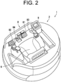
- FIG. 2 is a perspective view of the machine body 2 in the work machine 1.
- the work machine 1 is further provided with a steering unit 8 and a display device 9.
- the steering unit 8 and the display device 9 are installed on the machine body 2. Specifically, the steering unit 8 and the display device 9 are placed in front of the driver seat 6.
- the steering unit 8 includes various operation members for the worker to steer the work machine 1.
- the various operation members include a swing pedal 81, a PTO pedal 82, a boom operation lever 83, and an arm operation lever 84.
- the swing pedal 81 is a foot pedal.
- the worker operates the swing pedal 81 with his or her foot.
- the worker operates the swing pedal 81, making it possible to rotate, by means of a swing cylinder, the boom 3 to the left and right via a swing bracket.
- the PTO pedal 82 is a foot pedal. The worker operates the PTO pedal 82 with his/her foot. The worker operates the PTO pedal 82, making it possible to drive an attachment attached to a PTO port.
- the worker manually operates the boom operation lever 83 and the arm operation lever 84.
- the worker operates the boom operation lever 83, making it possible to operate the boom 3.
- the worker operates the arm operation lever 84, making it possible to operate the arm 4.
- the display device 9 displays various screens. For details, as described below with reference to FIGS. 4 to 6 , etc., the display device 9 displays a home screen 510. Also, as described below with reference to FIG. 7 , etc., the display device 9 displays an error information screen 520. Also, as described below with reference to FIG. 8 , etc., the display device 9 displays an error information detail screen 530.
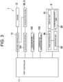
- FIG. 3 shows a block diagram of the work machine 1.
- the work machine 1 is further provided with a first controller 11, the engine 12, and a second controller 13.
- the work machine 1 is provided with various sensors.
- the work machine 1 is provided with an acceleration sensor 101, a cooling water temperature sensor 102, and a hydraulic oil temperature sensor 103.
- the steering unit 8 further includes an acceleration volume 85.
- the engine 12 generates a drive force that drives the run device 7.
- the second controller 13 controls the engine 12 based on a command sent from the first controller 11.
- the second controller 13 includes, for example, a processing unit that executes various processes, a storage unit that stores various programs and various data, and an input/output interface.
- the processing unit includes, for example, a processor, which executes various calculations, such as CPU (Central Processing Unit) or MPU (Micro Processing Unit). Or, the processing unit may be composed of a general-purpose calculator.
- the storage unit includes, for example, a semiconductor memory.
- the storage unit includes a RAM (Random Access Memory) and a ROM (Read Only Memory), for example.
- the storage unit may further include non-volatile memories such as an EEPROM (registered trademark) or a flash memory.
- the second controller 13 includes, for example, an ECU (Electronic Control Unit).
- the worker manually operates the acceleration volume 85.
- the acceleration volume 85 is electrically connected to the second controller 13.
- the worker operates the acceleration volume 85 forward or reverse, thus increasing or decreasing the engine 12's rpm.
- the acceleration sensor 101 detects an operation position (rotational position) of the acceleration volume 85.
- the first controller 11 sends a command that controls the amount and timing of fuel injection into the engine 12 based on the acceleration volume 85's operation position detected by the acceleration sensor 101.
- the first controller 11 determines whether or not the acceleration volume 85's operation position detected by the acceleration sensor 101 shows an abnormal value (outlier). By comparing the acceleration volume 85's operation position detected by the acceleration sensor 101 with a threshold value, for example, the first controller 11 may determine whether or not the acceleration volume 85's operation position detected by the acceleration sensor 101 shows the abnormal value (outlier).
- the cooling water temperature sensor 102 detects the temperature of the cooling water circulating in the engine 12.
- the first controller 11 determines whether or the cooling water's temperature detected by the cooling water temperature sensor 102 shows an abnormal value (outlier). By comparing the cooling water's temperature detected by the cooling water temperature sensor 102 with a threshold value, for example, the first controller 11 may determine whether or the cooling water's temperature detected by the cooling water temperature sensor 102 shows the abnormal value (outlier).
- the hydraulic oil temperature sensor 103 detects the hydraulic oil's temperature.
- the first controller 11 determines whether or not the hydraulic oil's temperature detected by the hydraulic oil temperature sensor 103 shows an abnormal value (outlier). By comparing the hydraulic oil's temperature detected by the hydraulic oil temperature sensor 103 with a threshold value, for example, the first controller 11 may determine whether or not the hydraulic oil's temperature detected by the hydraulic oil temperature sensor 103 shows the abnormal value (outlier).
- the first controller 11 controls various portions of the work machine 1.
- the first controller 11 includes, for example, a processing unit that executes various processes, a storage unit that stores various programs and various data, and an input/output interface.
- the first controller 11 is composed of, for example, an ECU.
- the first controller 11 When detecting that an error has occurred to the work machine 1, the first controller 11 sends alarm information to the display device 9.
- the alarm information shows that the error is occurring to the work machine 1.
- the alarm information includes information that shows an error name, an error code, and an alarm level.
- the alarm information includes information that shows a method of dealing with the error.
- the error name, the error code, the alarm level, and the method of dealing with errors are preset for each error that is expected to occur to the work machine 1.
- the first controller 11 is an example of a sending unit.
- the first controller 11 when determining that the accelerator volume 85's operation position detected by the acceleration sensor 101 shows the abnormal value (outlier), the first controller 11 sends the alarm information to the display device 9. Similarly, when determining that the cooling water's temperature detected by the cooling water temperature sensor 102 shows the abnormal value (outlier), the first controller 11 sends the alarm information to the display device 9. Further, when determining that the hydraulic oil's temperature detected by the hydraulic oil temperature sensor 103 shows the abnormal value (outlier), the first controller 11 sends the alarm information to the display device 9.
- the display device 9 has a display unit 91, an alarm sound output unit 92, an operation unit 93, and a third controller 94.
- the display unit 91 is composed of a display, such as a liquid crystal display or an organic EL display. Based on the alarm information, the display unit 91 displays an image that shows that the error is occurring. Specifically, based on the alarm information, the third controller 94 causes the display unit 91 to display the image that shows that the error is occurring.
- the alarm sound output unit 92 outputs an alarm sound based on the alarm information. Specifically, based on the alarm information, the third controller 94 causes the alarm sound output unit 92 to output the alarm sound. That is, when the error occurs to the work machine 1, the alarm sound output unit 92 outputs the alarm sound. Thus, the worker can aurally recognize that the error is occurring to the work machine 1.
- the alarm sound output unit 92 is, for example, a buzzer.
- the third controller 94 may cause the alarm sound output unit 92 to output the alarm sound that is different according to the alarm level.
- the alarm levels include a first alarm level and a second alarm level.
- the third controller 94 may cause the alarm sound output unit 92 to output a continuous sound.
- the third controller 94 may cause the alarm sound output unit 92 to output an intermittent sound. With the alarm sound output unit 92 outputting the alarm sound that is different according to the alarm level, the worker can aurally recognize the alarm level of the error occurring to the work machine 1.
- the operation unit 93 is operated by the worker, thereby to receive various instructions.
- the worker operates the operation unit 93, making it possible to input various instructions to the third controller 94.
- the operation unit 93 is an example of a reception unit.
- the operation unit 93 receives an instruction to stop the output of alarm the sound.
- the third controller 94 Based on various information sent from the first controller 11, the third controller 94 causes the display unit 91 to display various screens.
- the third controller 94 includes, for example, a processing unit that executes various processes, a storage unit that stores various programs and various data, and an input/output interface.
- the third controller 94 is composed of, for example, an ECU.
- the third controller 94 is an example of a control unit.
- FIG. 4 is a diagram showing the display device 9 of the present embodiment.
- FIG. 4 shows the display device 9 displaying the home screen 510.
- the home screen 510 is an example of a first screen.
- the home screen 510 displays, for example, a remaining fuel level gauge, a cooling water temperature gauge, and a hydraulic oil temperature gauge.
- the home screen 510 has a first selection item display area 511 and a first notification area 512.
- the first selection item display area 511 displays various selection items. Specifically, the first selection item display area 511 displays letter images (letter string images) or marks showing various selection items. Marks are, for example, an icon, shape, or a pictogram.
- the operation unit 93 includes a plurality of operation switches. Specifically, the operation unit 93 includes a first operation switch 931 to a sixth operation switch 936.
- the first operation switch 931 to the sixth operation switch 936 each correspond one of the selection items displayed in the first selection item display area 511.
- the first operation switch 931 to the sixth operation switch 936 are each assigned a function of selecting one of the selection items displayed in the first selection item display area 511. That is, the first operation switch 931 to the sixth operation switch 936 each receive an instruction for selecting the corresponding item.
- the sixth operation switch 936 is assigned the function of selecting a selection item T1.
- the selection item T1 is an item for switching the information displayed in the first notification area 512.
- the third controller 94 switches the information, which is displayed in the first notification area 512, between information that shows the engine 12's RPM and information that shows the remaining fuel level.
- the home screen 510 further has a second notification area 513.
- the third controller 94 causes the second notification area 513 to display an error notification image 610 and an alarm mark image 620 which are to be described with reference to FIG. 5 , etc.
- FIG. 4 shows the home screen 510 that is displayed at the display unit 91 when the first controller 11 has not detected the occurrence of the error.
- the error notification image 610 and the alarm mark image 620 are not displayed in the second notification area 513.
- the second notification area 513 is described as "error notification area 513".
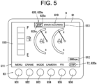
- FIG. 5 is a diagram showing the display device 9 displaying the error notification image 610 and the alarm mark image 620.
- the third controller 94 causes the home screen 510 to display the error notification image 610 and the alarm mark image 620.
- the worker can visually recognize that the error is occurring to the work machine 1.
- the third controller 94 causes the error notification area 513 to display the error notification image 610 and the alarm mark image 620.
- the error notification image 610 and the alarm mark image 620 are each an example of an image that shows that the error is occurring.
- the error notification image 610 is a letter string image that shows that the error is occurring.
- the alarm mark image 620 is a mark image that shows that the error is occurring. Specifically, the alarm mark image 620 shows the alarm level.
- the alarm levels include the first alarm level and the second alarm level.
- the first alarm level is set for the error due to which the work machine 1 needs to be stopped.
- the second alarm level is set for the error due to which the work machine 1 does not need to be stopped. Thus, when only the second alarm level error is occurring, the worker may continue the work by the work machine 1.
- FIG. 5 shows the alarm mark image 620 that corresponds to the first alarm level.
- the alarm mark image 620 that corresponds to the first alarm level is referred to as "first alarm mark image 620a".
- the third controller 94 causes the error notification area 513 to display the first alarm mark image 620a.
- the worker can visually recognize that the first alarm level error is occurring to the work machine 1.
- the third controller 94 determines a background color of the error notification area 513. In other words, the third controller 94 changes the background color of the error notification area 513 according to the alarm level. Specifically, when the first alarm level error is occurring, the background color of the error notification area 513 is determined to be "red". Thus, from the background color of the error notification area 513, the worker can visually recognize that the first alarm level error is occurring to the work machine 1.
- the first alarm mark image 620a includes a letter string image 621a and a graphic image 622a.
- the letter string image 621a is placed inside the graphic image 622a.
- the graphic image 622a's outline and the letter string image 621a are white, and a color (background color) inside the graphic image 622a is red.
- the display device 9 is further described with reference to FIGS. 1 to 5 .
- the third controller 94 causes the first selection item display area 511 to display a selection item T2.
- the selection item T2 is an item that is selected when the screen to be displayed at the display unit 91 is caused to transition from the home screen 510 to the error information screen 520 to be described with reference to FIG. 7 .
- the operation unit 93 can receive an instruction for transition to the error information screen 520.
- the function of selecting the selection item T2 is assigned to one of the first operation switch 931 to the sixth operation switch 936.
- the selection item T2 is displayed in place of the selection item T1 described with reference to FIG. 4 .
- the function of selecting the selection item T2 is assigned to the sixth operation switch 936.
- the alarm mark image 620 is displayed as the selection item T2.
- the alarm mark image 620 is the first alarm mark image 620a.
- displaying the alarm mark image 620 as the selection item T2 causes the worker to more easily recognize the operation switch for transitioning to the error information screen 520.
- displaying the first alarm mark image 620a as the selection item T2 causes the worker to visually recognize that the first alarm level error is occurring to the work machine 1.
- FIG. 6 is a diagram showing the home screen 510 that is displayed on the display device 9 when only the second alarm level error is occurring.
- the third controller 94 causes the error notification area 513 to display the alarm mark image 620 that corresponds to the second alarm level.
- the alarm mark image 620 that corresponds to the second alarm level is referred to as "second alarm mark image 620b".
- the error notification area 513 displays the second alarm mark image 620b.
- the third controller 94 determines the background color of the error notification area 513 to be "yellow". Thus, from the background color of the error notification area 513, the worker can visually recognize that only the second alarm level error is occurring to the work machine 1.
- the third controller 94 causes the first selection item display area 511 to display the second alarm mark image 620b as the selection item T2.
- displaying the second alarm mark image 620b as the selection item T2 causes the worker to visually recognize that only the second alarm level error is occurring to the work machine 1.
- the second alarm mark image 620b includes a letter string image 621b and a graphic image 622b.
- the letter string image 621b is placed inside the graphic image 622b.
- the graphic image 622b's outline and the letter string image 621b are white, and a color (background color) inside the graphic image 622b is yellow.
- FIG. 7 is a diagram showing the display device 9 displaying the error information screen 520.
- the error information screen 520 is an example of a second screen.
- the third controller 94 causes the display unit 91 to display the error information screen 520. That is, when the sixth operation switch 936 is pressed down with the selection item T2 being displayed in the first selection item display area 511, the third controller 94 causes the display unit 91 to display the error information screen 520.
- the error information screen 520 is a screen that shows the error that is occurring to the work machine 1.
- the error information screen 520 has a second selection item display area 521.
- the second selection item display area 521 displays various selection items. Specifically, the second selection item display area 521 displays letter images (letter string images) or marks showing various selection items.
- the selection items T11 and T12 are displayed.
- the selection item T11 is an item that is selected for returning to the home screen 510.
- the selection item T12 is an item that is selected for stopping the alarm sound's output.
- the first operation switch 931 When the display unit 91 is displaying the error information screen 520, the first operation switch 931 is assigned the function of selecting the selection item T11. That is, to the first operation switch 931, the third controller 94 assigns a function of receiving an instruction for transition from the error information screen 520 to the home screen 510.
- the third controller 94 causes the display unit 91 to display the home screen 510.
- the third controller 94 causes the display unit 91 to display the home screen 510.
- the transition from the error information screen 520 to the home screen 510 is described as "transition to home screen 510".
- the fifth operation switch 935 is assigned the function of selecting the selection item T12. That is, to the fifth operation switch 935, the third controller 94 assigns the function of receiving an output stop instruction to stop the alarm sound's output.
- the third controller 94 stops the alarm sound's output by the alarm sound output unit 92.
- the third controller 94 stops the alarm sound's output by the alarm sound output unit 92.
- the third controller 94 in the case where the first alarm level error is occurring to the work machine 1; the third controller 94, with the operation unit 93, after having received the output stop instruction, receiving the instruction for transition to the home screen 510, causes the display unit 91 to display the home screen 510, and causes the alarm sound output unit 92 to output the alarm sound.
- the alarm sound's output is stopped; it is possible, after the screen to be displayed at the display unit 91 is returned to the home screen 510, to cause the worker to recognize again that the first alarm level error is occurring to the work machine 1.
- the third controller 94 causes the display unit 91 to display the home screen 510, and maintains the stop of the alarm sound's output.
- the second alarm level error is the error due to which the work machine 1 does not need to be stopped; thus, when only the second alarm level error is occurring, the worker may continue the work by the work machine 1.
- the worker when the worker, after having instructed for stopping the alarm sound's output, returns the screen, which is displayed at the display unit 91, to the home screen 510 thereby to continue the work by the work machine 1, the worker can do the work without being disturbed by the alarm sound.
- the third controller 94 when the operation unit 93 receives the instruction for transition to the home screen 510, the third controller 94 causes the display unit 91 to display the home screen 510 described with reference to FIG. 5 or the home screen 510 described with reference to FIG. 6 . Specifically, in the case where the first alarm level error is occurring to the work machine 1; when the operation unit 93 receives the instruction for transition to the home screen 510, the third controller 94 causes the display unit 91 to display the home screen 510 described with reference to FIG. 5 .
- the third controller 94 causes the display unit 91 to display the home screen 510 described with reference to FIG. 6 .
- the third controller 94 causes the first selection item display area 511 to display the selection item T2.
- the worker after the screen to be displayed at the display unit 91 is returned from the error information screen 520 to the home screen 510, can again cause the display unit 91 to display the error information screen 520.
- the home screen 510 can cause the worker to visually recognize that the error is occurring to the work machine 1.
- the display device 9 is to be further described with reference to FIGS. 1 to 7 .
- the third controller 94 causes the error information screen 520 to display the error information 700.
- the error information 700 shows the content of the error occurring to the work machine 1.
- the worker can easily recognize the content of the error occurring to the work machine 1.
- the error information 700 shows an error code 701, an error name 702, and an alarm mark image 620.
- the third controller 94 causes the error information screen 520 to display the error code 701, the error name 702, and the alarm mark image 620 in association.
- the worker can be caused to easily recognize the content of the error occurring to the work machine 1. Also, the worker can be caused to easily recognize the alarm level of the error occurring to the work machine 1.
- the third controller 94 causes the error information screen 520 to display a list of the error information 700.
- the worker can easily recognize content of each of the plural errors.
- FIG. 7 shows an example of displaying five pieces of error information 700 on the error information screen 520.
- the error information screen 520 displays first error information 710 to fifth error information 750.
- the error information screen 520 has a first error information display area 522 to a fifth error information display areas 526.
- the first error information display area 522 to the fifth error information display area 526 are placed above the second selection item display area 521.
- the first error information display area 522 to the fifth error information display area 526 are arranged in this order toward the second selection item display area 521.
- the third controller 94 causes the first error information display area 522 to the fifth error information display area 526 to respectively display the first error information 710 to the fifth error information 750.
- the first error information 710 and the second error information 720 show the first alarm level
- the third error information 730 to the fifth error information 750 show the second alarm level.
- the third controller 94 causes the plural pieces of error information 700 to be displayed according to each alarm level.
- the worker can be caused to easily recognize the alarm level of the error occurring to the work machine 1.
- the third controller 94 arranges the plural pieces of error information 700 with the same alarm level.
- the first error information 710 and the second error information 720 are arranged in the order of occurrence of the error.
- the third error information 730 to the fifth error information 750 are similarly arranged in the order of occurrence of the error.
- the third controller 94 causes the error information 700 showing the first alarm level to be displayed at the upper step of the error information 700 showing the second alarm level. That is, the third controller 94 causes the error information 700 with the higher alarm level to be displayed at the upper step of the error information 700 with the lower alarm level. Thus, the third controller 94 causes the plural pieces of error information 700 in a descending order from the error information 700 with the higher alarm level. Thus, according to the present embodiment, the worker can be caused to easily recognize the alarm level of the error occurring to the work machine 1.
- the third controller 94 determines the background colors of the first error information display area 522 to the fifth error information display area 526. For example, the third controller 94 determines the background color of the area, which displays the error information 700 showing the first alarm level, to be red, and the background color of the area, which displays the error information 700 showing the second alarm level, to be yellow. In the example shown in FIG. 7 , the background colors of the first error information display area 522 and the second error information display area 523 are red, and the background colors of the third error information display area 524 to the fifth error information display area 526 are yellow.
- the first error information display area 522 to the fifth error information display area 526 are an example of partitioned areas.
- the display device 9 is to be further described with reference to FIGS. 1 to 7 .
- the third controller 94 causes the error information screen 520 to display a cursor 705.
- the cursor 705 designates the error information 700.
- the first error information 710 is designated by the cursor 705.
- the second selection item display area 521 further displays a selection item T13, a selection item T14, and a selection item T15.
- the selection item T13 is an item that is selected when moving the cursor 705 downward.
- the selection item T14 is an item that is selected when moving the cursor 705 upward.
- the selection item T15 is an item that is selected when displaying the error information detail screen 530 described with reference to FIG. 8 .
- the third operation switch 933 is assigned the function of selecting the selection item T13.
- the third controller 94 moves the cursor 705 to a position one step lower.
- the fourth operation switch 934 is assigned the function of selecting the selection item T14.
- the third controller 94 moves the cursor 705 to a position one step higher.
- the sixth operation switch 936 is assigned the function of selecting the selection item T15.
- the third controller 94 causes the screen, which is to be displayed at the display unit 91, to transition from the error information screen 520 to the error information detail screen 530 described with reference to FIG. 8 .
- the third controller 94 with the sixth operation switch 936 pressed down, causes the display unit 91 to display the screen showing detail of the error information 700 designated by the cursor 705.
- FIG. 8 is a diagram showing the display device 9 displaying the error information detail screen 530.
- the third controller 94 causes the display unit 91 to display the error information detail screen 530.
- the error information detail screen 530 displays an alarm mark image 620, an error code 701, an error name 702, and a message 703.
- the message 703 is a letter string image that shows the method of dealing with the error.
- the error information detail screen 530 has a third selection item display area 531.
- the third selection item display area 531 displays various selection items. Specifically, the third selection item display area 531 displays letter images (letter string images) or marks showing various selection items.
- the third selection item display area 531 displays a selection item T21 and a selection item T22.
- the selection item T21 is an item that is selected when returning to the error information screen 520.
- Selection item T22 is an item that is selected when stopping the alarm sound's output.
- the first operation switch 931 is assigned the function of selecting the selection item T21.
- the third controller 94 causes the display unit 91 to display the error information screen 520.
- the fifth operation switch 935 is assigned the function of selecting the selection item T22.
- the third controller 94 stops the alarm sound's output by the alarm sound output unit 92.
- FIG. 9 is a flowchart showing a process executed by the third controller 94 in the display device 9. Specifically, FIG. 9 shows the process executed by the third controller 94 after the alarm information is sent from the first controller 11 to the third controller 94.
- the third controller 94 executes the processes of steps S1 and S2.
- the third controller 94 causes the alarm sound output unit 92 to output the alarm sound (step S1).
- the third controller 94 causes the error notification area 513 of the home screen 510 to display the error notification image 610 (step S2).
- the third controller 94 causes the error notification area 513 of the home screen 510 to display the alarm mark image 620 (step S2). Specifically, the third controller 94, when the alarm level shown by the alarm information is the first alarm level, causes the first alarm mark image 620a to be displayed, and when the alarm level shown by the alarm information is the second alarm level, causes the second alarm mark image 620b to be displayed. When the first alarm level error occurs, the third controller 94 causes the first alarm mark image 620a to be displayed until the error is resolved.
- the third controller 94 changes, to the selection item T2, one of the selection items displayed in the first selection item display area 511 (step S2), and ends the processes shown in FIG. 9 .
- the third controller 94 changes the selection item T1 to the selection item T2.
- FIG. 10 is a flowchart showing other processes executed by the third controller 94 in the display device 9. Specifically, FIG. 10 shows the processes executed by the third controller 94 after the selection item T11 is selected during the displaying of the error information screen 520. That is, FIG. 10 shows the processes executed by the third controller 94 after the first operation switch 931 is pressed down when the error information screen 520 is displayed at the display unit 91.
- the third controller 94 determines whether or not the alarm sound's output is stopped (step S11).
- the third controller 94 determines, based on the alarm information, whether or not the alarm level of the error occurring to the work machine 1 includes the first alarm level (step S12). Further, the third controller 94 stores the alarm information received from the first controller 11.
- the third controller 94 When determining that the alarm level of the error occurring to the work machine 1 includes the first alarm level (step S12 Yes), the third controller 94 causes the alarm sound output unit 92 to output the alarm sound (step S13), and causes the display unit 91 to display the home screen 510 (step S14). Upon causing the display unit 91 to display the home screen 510, the third controller 94 ends the processes shown in FIG. 10 .
- the third controller 94 causes the display unit 91 to display the home screen 510 (step S14), and ends the processes shown in FIG. 10 .
- the third controller 94 When determining that the alarm level of the error occurring to the work machine 1 does not include the first alarm level (step S12 No), the third controller 94 causes the display unit 91 to display the home screen 510 (step S14), and ends the processes shown in FIG. 10 .
- the operation unit 93 can receive the output stop instruction. Thus, regardless of the type of error, the alarm sound's output can be stopped.
- FIGS. 1 to 10 The embodiment of the present invention has been described with reference to the accompanying drawings ( FIGS. 1 to 10 ). However, the present invention is not limited to the above embodiment, and can be executed in various aspects in the range without departing from its spirit.
- the plurality of components disclosed in the above embodiment may be properly modified. For example, one of all the components shown in one embodiment may be added to the component of the other embodiment, or some components of all the components shown in one embodiment may be removed from the embodiment.
- the third controller 94 maintained the output stop of the alarm the sound; but as in the case where the first alarm level error is occurring, the third controller 94 may output the alarm sound.
- the work machine 1 was a backhoe, but the work machine 1 is not limited to the backhoe.
- the work machine 1 may be any machine as long as being provided with a display device that controls the alarm sound output unit.
- the operation unit 93 included a plurality of operation switches (first operation switch 931 to sixth operation switch 936), but the operation unit 93 is not limited to the plurality of operation switches.
- the operation unit 93 may include a touch sensor. The touch sensor may be superimposed on a display face of the display unit 91.
- the operation unit 93 may include a jog dial.
- the third controller 94 executed the processes shown in FIGS. 9 and 10
- the first controller 11 may execute the processes shown in FIGS. 9 and 10
- the first controller 11 and the third controller 94 in cooperation may execute the processes shown in FIGS. 9 and 10 .
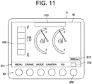
- the third controller 94 changed, to the selection item T2, one of the selection items displayed in the first selection item display area 511, but as shown in FIG. 11 , a specific area 514 for displaying the selection item T2 may be provided in the first selection item display area 511.
- FIG. 11 shows the modified example of the display device 9 of the present embodiment.
- FIG. 11 shows the modified example of the home screen 510 that is displayed by the display device 9 before the alarm information is sent from the first controller 11 to the third controller 94.
- the home screen 510 shown in FIG. 11 has the specific area 514 in the first selection item display area 511.
- the first controller 11 has not detected the occurrence of the error, no selection item is displayed in the specific area 514.
- the third controller 94 causes the specific area 514 to display the selection item T2.
- the present invention is useful for a display device and a work machine.
Landscapes
- Engineering & Computer Science (AREA)
- General Engineering & Computer Science (AREA)
- Mining & Mineral Resources (AREA)
- Civil Engineering (AREA)
- Structural Engineering (AREA)
- Physics & Mathematics (AREA)
- General Physics & Mathematics (AREA)
- Mechanical Engineering (AREA)
- Theoretical Computer Science (AREA)
- Human Computer Interaction (AREA)
- Electromagnetism (AREA)
- Computer Security & Cryptography (AREA)
- Automation & Control Theory (AREA)
- Component Parts Of Construction Machinery (AREA)
Abstract
Description
- The present invention relates to a display device and a work machine provided with the same.
- A display device that, at the time of occurrence of an error, causes an alarm sound output unit to output an alarm sound is known. For example,
Patent Literature 1 discloses a work vehicle provided with a display device that controls an alarm buzzer. Specifically, the display device is provided with a plurality of operation switches, and a display unit. The display device, at the time of occurrence of an abnormality, causes an alarm buzzer to sound. Also, the display device determines whether or not a buzzer cancel function is enabled for the abnormality that has occurred. When the abnormality for which the buzzer cancel function is enabled occurs, the display device assigns the buzzer cancel function to one of the plural operation switches and displays a buzzer cancel icon at a display position that corresponds to that operation switch. When the worker presses down the operation switch to which the buzzer cancel function is assigned, the display device causes the alarm buzzer to stop sounding. Meanwhile, when the abnormality for which the buzzer cancel function is not enabled occurs, the display device leaves the alarm buzzer sounding. - Patent Literature 1: PCL International Publication No.
WO 2016/016978 - However, when the abnormality (error) for which the buzzer cancel function is not enabled occurs, the display device of
Patent Literature 1 cannot stop the alarm buzzer. Thus, the alarm sound, as the case may be, is being output even when a service staff is to inspect or repair an abnormal place, and the service staff's work may be disturbed by the alarm sound. - In view of the above issue, the present invention has been made, and it is an object of the present invention to provide a display device capable of stopping output of an alarm sound regardless of the type of error, and a work machine provided with the same.
- A display device according to the present invention includes a display unit, a control unit that, an alarm sound output unit, and a reception unit. The display unit displays a first screen. The control unit, based on alarm information, causes the first screen to display an image that shows that an error is occurring. The alarm sound output unit outputs an alarm sound based on the alarm information. The reception unit receives a first instruction that indicates a transition to a second screen that shows a content of the error. The control unit, when the reception unit receives the first instruction, causes the display unit to display the second screen. The control unit, with the display unit displaying the second screen, assigns, to the reception unit, a function of receiving an output stop instruction that indicates an instruction to stop the alarm sound's output and a function of receiving a second instruction that indicates an instruction of a transition from the second screen to the first screen. The control unit, with the reception unit receiving the output stop instruction, stops the alarm sound's output by the alarm sound output unit. The control unit, when the reception unit receives the second instruction after having received the output stop instruction, causes the display unit to display the first screen, and causes the alarm sound output unit to output the alarm sound.
- According to the present invention, output of an alarm sound can be stopped regardless of the type of error.
-
-
FIG. 1 is a side view of a work machine according to an embodiment of the present invention. -
FIG. 2 is a perspective view of a machine body in the work machine. -
FIG. 3 is a block diagram of the work machine. -
FIG. 4 is a diagram showing a display device according to the embodiment of the present invention. -
FIG. 5 is a diagram showing the display device displaying an error notification image and an alarm mark image. -
FIG. 6 is a diagram showing a home screen displayed on the display device when only a second alarm level error is occurring. -
FIG. 7 is a diagram showing the display device displaying an error information screen. -
FIG. 8 is a diagram showing the display device displaying an error information detail screen. -
FIG. 9 is a flowchart showing a process executed by a third controller in the display device. -
FIG. 10 is a flowchart showing another process executed by the third controller in the display device. -
FIG. 11 is a diagram showing a modified example of the display device according to the embodiment of the present invention. - The following is a description of an embodiment according to a display device and work machine of the present invention with reference to the drawings (
FIGS. 1 to 11 ). Note that the present invention is not limited to the embodiment below. Any duplicated explanation is, as the case may be, properly omitted. Note that, in the drawings, the same reference signs are used for the same or equivalent components, and repeated descriptions are to be omitted. - First, a
work machine 1 of the present embodiment is to be described with reference toFIGS. 1 to 3 .FIG. 1 shows a side view of thework machine 1 of the present embodiment. As shown inFIG. 1 , thework machine 1 is a backhoe. The backhoe is a type of construction machine. Thework machine 1 of the present embodiment has amachine body 2, aboom 3, an arm 4, abucket 5, and arun device 7. Thework machine 1 of the present embodiment is further provided with aboom actuator 30, anarm actuator 40, and anattachment actuator 50. - The
machine body 2 has adriver seat 6. A worker sits on thedriver seat 6 and operates thework machine 1. Themachine body 2 is supported by therun device 7. Themachine body 2 may be swingably supported by therun device 7. Themachine body 2 is provided with an engine 12 (seeFIG. 3 ), a fuel tank, a battery, a hydraulic system, and a hydraulic oil tank. Also, themachine body 2 has a hood that houses the engine 12 (seeFIG. 3 ), the fuel tank, the battery, the hydraulic system, and the hydraulic oil tank, and thedriver seat 6 is placed on the hood. - The
boom 3 is so supported by themachine body 2 as to swing around a first rotation supporting point P1. Specifically, a base end portion of theboom 3 is axially supported by themachine body 2. The first rotation supporting point P1 is a rotary axis that extends along the right/left direction that is observed when thedriver seat 6 is viewed from the front. Hereafter, the right/left direction that is observed when thedriver seat 6 is viewed from the front, as the case may be, is described as the "right/left direction". - The
boom actuator 30 actuates theboom 3. Specifically, theboom actuator 30, by extending and retracting, swings theboom 3 around the first rotation supporting point P1. In detail, controlling the hydraulic oil supplied to theboom actuator 30 and the hydraulic oil discharged from theboom actuator 30 extends and retracts theboom actuator 30. Thus, theboom actuator 30 is extended and retracted by the hydraulic oil. - The arm 4 is so supported by the
boom 3 as to swing around a second rotation supporting point P2. Specifically, a base end portion of the arm 4 is axially supported at a tip portion of theboom 3. The second rotation supporting point P2 is a rotary axis extending along the right/left direction. - The
arm actuator 40 actuates the arm 4. Specifically, thearm actuator 40, by extending and retracting, swings the arm 4 around the second rotation supporting point P2. In detail, controlling the hydraulic oil supplied to thearm actuator 40 and the hydraulic oil discharged from thearm actuator 40 extends and retracts thearm actuator 40. Thus, thearm actuator 40 is extended and retracted by the hydraulic oil. - The
bucket 5 is a type of attachment. Thebucket 5 is so supported by the arm 4 as to swing around a third rotation supporting point P3. Specifically, thebucket 5 is axially supported at a tip portion of the arm 4. The third rotation supporting point P3 is a rotary axis extending along the right/left direction. - The attachment actuator 50 actuates the
bucket 5. Specifically, theattachment actuator 50, by extending and retracting, swings thebucket 5 around the third rotation supporting point P3. In detail, controlling the hydraulic oil supplied to theattachment actuator 50 and the hydraulic oil discharged from theattachment actuator 50 extends and retracts theactuator 50. Thus, theattachment actuator 50 is extended and retracted by the hydraulic oil. - The
run device 7 causes thework machine 1 to run. In the present embodiment, therun device 7 is a crawler-type run device. - Then, referring to
FIGS. 1 and2 , the configuration of thework machine 1 is described in more detail. Specifically, the configuration around thedriver seat 6 is to be described.FIG. 2 is a perspective view of themachine body 2 in thework machine 1. - As shown in
FIG. 2 , thework machine 1 is further provided with asteering unit 8 and adisplay device 9. Thesteering unit 8 and thedisplay device 9 are installed on themachine body 2. Specifically, thesteering unit 8 and thedisplay device 9 are placed in front of thedriver seat 6. - The
steering unit 8 includes various operation members for the worker to steer thework machine 1. The various operation members include aswing pedal 81, aPTO pedal 82, aboom operation lever 83, and anarm operation lever 84. - The
swing pedal 81 is a foot pedal. The worker operates theswing pedal 81 with his or her foot. The worker operates theswing pedal 81, making it possible to rotate, by means of a swing cylinder, theboom 3 to the left and right via a swing bracket. - The
PTO pedal 82 is a foot pedal. The worker operates thePTO pedal 82 with his/her foot. The worker operates thePTO pedal 82, making it possible to drive an attachment attached to a PTO port. - The worker manually operates the
boom operation lever 83 and thearm operation lever 84. The worker operates theboom operation lever 83, making it possible to operate theboom 3. Also, the worker operates thearm operation lever 84, making it possible to operate the arm 4. - The
display device 9 displays various screens. For details, as described below with reference toFIGS. 4 to 6 , etc., thedisplay device 9 displays ahome screen 510. Also, as described below with reference toFIG. 7 , etc., thedisplay device 9 displays anerror information screen 520. Also, as described below with reference toFIG. 8 , etc., thedisplay device 9 displays an errorinformation detail screen 530. - Then, the configuration of the
work machine 1 of the present embodiment is further described with reference toFIGS. 1 to 3 .FIG. 3 shows a block diagram of thework machine 1. As shown inFIG. 3 , thework machine 1 is further provided with afirst controller 11, theengine 12, and asecond controller 13. Also, thework machine 1 is provided with various sensors. In the present embodiment, thework machine 1 is provided with anacceleration sensor 101, a coolingwater temperature sensor 102, and a hydraulicoil temperature sensor 103. Also, thesteering unit 8 further includes an acceleration volume 85. - The
engine 12 generates a drive force that drives therun device 7. Thesecond controller 13 controls theengine 12 based on a command sent from thefirst controller 11. - The
second controller 13 includes, for example, a processing unit that executes various processes, a storage unit that stores various programs and various data, and an input/output interface. The processing unit includes, for example, a processor, which executes various calculations, such as CPU (Central Processing Unit) or MPU (Micro Processing Unit). Or, the processing unit may be composed of a general-purpose calculator. The storage unit includes, for example, a semiconductor memory. The storage unit includes a RAM (Random Access Memory) and a ROM (Read Only Memory), for example. The storage unit may further include non-volatile memories such as an EEPROM (registered trademark) or a flash memory. Thesecond controller 13 includes, for example, an ECU (Electronic Control Unit). - The worker manually operates the acceleration volume 85. The acceleration volume 85 is electrically connected to the
second controller 13. The worker operates the acceleration volume 85 forward or reverse, thus increasing or decreasing theengine 12's rpm. - The
acceleration sensor 101 detects an operation position (rotational position) of the acceleration volume 85. To thesecond controller 13, thefirst controller 11 sends a command that controls the amount and timing of fuel injection into theengine 12 based on the acceleration volume 85's operation position detected by theacceleration sensor 101. - Further, the
first controller 11 determines whether or not the acceleration volume 85's operation position detected by theacceleration sensor 101 shows an abnormal value (outlier). By comparing the acceleration volume 85's operation position detected by theacceleration sensor 101 with a threshold value, for example, thefirst controller 11 may determine whether or not the acceleration volume 85's operation position detected by theacceleration sensor 101 shows the abnormal value (outlier). - The cooling
water temperature sensor 102 detects the temperature of the cooling water circulating in theengine 12. Thefirst controller 11 determines whether or the cooling water's temperature detected by the coolingwater temperature sensor 102 shows an abnormal value (outlier). By comparing the cooling water's temperature detected by the coolingwater temperature sensor 102 with a threshold value, for example, thefirst controller 11 may determine whether or the cooling water's temperature detected by the coolingwater temperature sensor 102 shows the abnormal value (outlier). - The hydraulic
oil temperature sensor 103 detects the hydraulic oil's temperature. Thefirst controller 11 determines whether or not the hydraulic oil's temperature detected by the hydraulicoil temperature sensor 103 shows an abnormal value (outlier). By comparing the hydraulic oil's temperature detected by the hydraulicoil temperature sensor 103 with a threshold value, for example, thefirst controller 11 may determine whether or not the hydraulic oil's temperature detected by the hydraulicoil temperature sensor 103 shows the abnormal value (outlier). - The
first controller 11 controls various portions of thework machine 1. Thefirst controller 11 includes, for example, a processing unit that executes various processes, a storage unit that stores various programs and various data, and an input/output interface. Thefirst controller 11 is composed of, for example, an ECU. - When detecting that an error has occurred to the
work machine 1, thefirst controller 11 sends alarm information to thedisplay device 9. The alarm information shows that the error is occurring to thework machine 1. In detail, the alarm information includes information that shows an error name, an error code, and an alarm level. Also, the alarm information includes information that shows a method of dealing with the error. The error name, the error code, the alarm level, and the method of dealing with errors are preset for each error that is expected to occur to thework machine 1. In the present embodiment, thefirst controller 11 is an example of a sending unit. - Specifically, when determining that the accelerator volume 85's operation position detected by the
acceleration sensor 101 shows the abnormal value (outlier), thefirst controller 11 sends the alarm information to thedisplay device 9. Similarly, when determining that the cooling water's temperature detected by the coolingwater temperature sensor 102 shows the abnormal value (outlier), thefirst controller 11 sends the alarm information to thedisplay device 9. Further, when determining that the hydraulic oil's temperature detected by the hydraulicoil temperature sensor 103 shows the abnormal value (outlier), thefirst controller 11 sends the alarm information to thedisplay device 9. - The
display device 9 has adisplay unit 91, an alarmsound output unit 92, anoperation unit 93, and athird controller 94. - The
display unit 91 is composed of a display, such as a liquid crystal display or an organic EL display. Based on the alarm information, thedisplay unit 91 displays an image that shows that the error is occurring. Specifically, based on the alarm information, thethird controller 94 causes thedisplay unit 91 to display the image that shows that the error is occurring. - The alarm
sound output unit 92 outputs an alarm sound based on the alarm information. Specifically, based on the alarm information, thethird controller 94 causes the alarmsound output unit 92 to output the alarm sound. That is, when the error occurs to thework machine 1, the alarmsound output unit 92 outputs the alarm sound. Thus, the worker can aurally recognize that the error is occurring to thework machine 1. The alarmsound output unit 92 is, for example, a buzzer. - The
third controller 94 may cause the alarmsound output unit 92 to output the alarm sound that is different according to the alarm level. Specifically, in the present embodiment, the alarm levels include a first alarm level and a second alarm level. For example, when the first alarm level error is occurring to thework machine 1, thethird controller 94 may cause the alarmsound output unit 92 to output a continuous sound. When only the second alarm level error is occurring to thework machine 1, thethird controller 94 may cause the alarmsound output unit 92 to output an intermittent sound. With the alarmsound output unit 92 outputting the alarm sound that is different according to the alarm level, the worker can aurally recognize the alarm level of the error occurring to thework machine 1. - The
operation unit 93 is operated by the worker, thereby to receive various instructions. The worker operates theoperation unit 93, making it possible to input various instructions to thethird controller 94. Theoperation unit 93 is an example of a reception unit. Theoperation unit 93, for example, receives an instruction to stop the output of alarm the sound. - Based on various information sent from the
first controller 11, thethird controller 94 causes thedisplay unit 91 to display various screens. Thethird controller 94 includes, for example, a processing unit that executes various processes, a storage unit that stores various programs and various data, and an input/output interface. Thethird controller 94 is composed of, for example, an ECU. Thethird controller 94 is an example of a control unit. - Then, the
display device 9 is to be further described with reference toFIGS. 1 to 10 .FIG. 4 is a diagram showing thedisplay device 9 of the present embodiment. In detail,FIG. 4 shows thedisplay device 9 displaying thehome screen 510. Thehome screen 510 is an example of a first screen. Thehome screen 510 displays, for example, a remaining fuel level gauge, a cooling water temperature gauge, and a hydraulic oil temperature gauge. - As shown in
FIG. 4 , thehome screen 510 has a first selectionitem display area 511 and afirst notification area 512. The first selectionitem display area 511 displays various selection items. Specifically, the first selectionitem display area 511 displays letter images (letter string images) or marks showing various selection items. Marks are, for example, an icon, shape, or a pictogram. - In the present embodiment, the
operation unit 93 includes a plurality of operation switches. Specifically, theoperation unit 93 includes afirst operation switch 931 to asixth operation switch 936. Thefirst operation switch 931 to thesixth operation switch 936 each correspond one of the selection items displayed in the first selectionitem display area 511. When thedisplay unit 91 is displaying thehome screen 510, thefirst operation switch 931 to thesixth operation switch 936 are each assigned a function of selecting one of the selection items displayed in the first selectionitem display area 511. That is, thefirst operation switch 931 to thesixth operation switch 936 each receive an instruction for selecting the corresponding item. - For example, the
sixth operation switch 936 is assigned the function of selecting a selection item T1. The selection item T1 is an item for switching the information displayed in thefirst notification area 512. For example, each time the worker presses down thesixth operation switch 936, thethird controller 94 switches the information, which is displayed in thefirst notification area 512, between information that shows theengine 12's RPM and information that shows the remaining fuel level. - The
home screen 510 further has asecond notification area 513. When thefirst controller 11 detects the occurrence of the error, thethird controller 94 causes thesecond notification area 513 to display anerror notification image 610 and analarm mark image 620 which are to be described with reference toFIG. 5 , etc.FIG. 4 shows thehome screen 510 that is displayed at thedisplay unit 91 when thefirst controller 11 has not detected the occurrence of the error. Thus, theerror notification image 610 and thealarm mark image 620 are not displayed in thesecond notification area 513. In the following description, thesecond notification area 513, as the case may be, is described as "error notification area 513". - Then, the
display device 9 is further described with reference toFIGS. 1 to 5 .FIG. 5 is a diagram showing thedisplay device 9 displaying theerror notification image 610 and thealarm mark image 620. - As shown in
FIG. 5 , based on the alarm information, thethird controller 94 causes thehome screen 510 to display theerror notification image 610 and thealarm mark image 620. Thus, the worker can visually recognize that the error is occurring to thework machine 1. - In detail, the
third controller 94 causes theerror notification area 513 to display theerror notification image 610 and thealarm mark image 620. Theerror notification image 610 and thealarm mark image 620 are each an example of an image that shows that the error is occurring. Theerror notification image 610 is a letter string image that shows that the error is occurring. Thealarm mark image 620 is a mark image that shows that the error is occurring. Specifically, thealarm mark image 620 shows the alarm level. - As described with reference to
FIG. 3 , in the present embodiment, the alarm levels include the first alarm level and the second alarm level. The first alarm level is set for the error due to which thework machine 1 needs to be stopped. The second alarm level is set for the error due to which thework machine 1 does not need to be stopped. Thus, when only the second alarm level error is occurring, the worker may continue the work by thework machine 1. -
FIG. 5 shows thealarm mark image 620 that corresponds to the first alarm level. Hereinafter, thealarm mark image 620 that corresponds to the first alarm level is referred to as "first alarm mark image 620a". When at least one first alarm level error is occurring to thework machine 1, thethird controller 94 causes theerror notification area 513 to display the first alarm mark image 620a. Thus, with the first alarm mark image 620a displayed on the home screen 510 (error notification area 513), the worker can visually recognize that the first alarm level error is occurring to thework machine 1. - Based on the alarm level, the
third controller 94 determines a background color of theerror notification area 513. In other words, thethird controller 94 changes the background color of theerror notification area 513 according to the alarm level. Specifically, when the first alarm level error is occurring, the background color of theerror notification area 513 is determined to be "red". Thus, from the background color of theerror notification area 513, the worker can visually recognize that the first alarm level error is occurring to thework machine 1. - Further, the first alarm mark image 620a includes a
letter string image 621a and agraphic image 622a. Theletter string image 621a is placed inside thegraphic image 622a. Thegraphic image 622a's outline and theletter string image 621a are white, and a color (background color) inside thegraphic image 622a is red. - Then, the
display device 9 is further described with reference toFIGS. 1 to 5 . As shown inFIG. 5 , based on the alarm information, thethird controller 94 causes the first selectionitem display area 511 to display a selection item T2. The selection item T2 is an item that is selected when the screen to be displayed at thedisplay unit 91 is caused to transition from thehome screen 510 to theerror information screen 520 to be described with reference toFIG. 7 . With the selection item T2 displayed in the first selectionitem display area 511, theoperation unit 93 can receive an instruction for transition to theerror information screen 520. - In detail, with the selection item T2 displayed in the first selection
item display area 511, the function of selecting the selection item T2 is assigned to one of thefirst operation switch 931 to thesixth operation switch 936. In the present embodiment, the selection item T2 is displayed in place of the selection item T1 described with reference toFIG. 4 . Thus, the function of selecting the selection item T2 is assigned to thesixth operation switch 936. - Further, in the present embodiment, the
alarm mark image 620 is displayed as the selection item T2. In the example shown inFIG. 5 , thealarm mark image 620 is the first alarm mark image 620a. Thus, displaying thealarm mark image 620 as the selection item T2 causes the worker to more easily recognize the operation switch for transitioning to theerror information screen 520. Further, displaying the first alarm mark image 620a as the selection item T2 causes the worker to visually recognize that the first alarm level error is occurring to thework machine 1. - Then, the
display device 9 is to be further described with reference toFIGS. 1 to 6 .FIG. 6 is a diagram showing thehome screen 510 that is displayed on thedisplay device 9 when only the second alarm level error is occurring. - As shown in
FIG. 6 , when only the second alarm level error is occurring, thethird controller 94 causes theerror notification area 513 to display thealarm mark image 620 that corresponds to the second alarm level. Hereinafter, thealarm mark image 620 that corresponds to the second alarm level is referred to as "second alarm mark image 620b". According to the present embodiment, when only the second alarm level error is occurring, theerror notification area 513 displays the second alarm mark image 620b. Thus, with the second alarm mark image 620b displayed on the home screen 510 (error notification area 513), the worker can visually recognize that only the second alarm level error is occurring to thework machine 1. - When only the second alarm level error is occurring, the
third controller 94 determines the background color of theerror notification area 513 to be "yellow". Thus, from the background color of theerror notification area 513, the worker can visually recognize that only the second alarm level error is occurring to thework machine 1. - When only the second alarm level error is occurring, the
third controller 94 causes the first selectionitem display area 511 to display the second alarm mark image 620b as the selection item T2. Thus, displaying the second alarm mark image 620b as the selection item T2 causes the worker to visually recognize that only the second alarm level error is occurring to thework machine 1. - Also, the second alarm mark image 620b includes a
letter string image 621b and agraphic image 622b. Theletter string image 621b is placed inside thegraphic image 622b. Thegraphic image 622b's outline and theletter string image 621b are white, and a color (background color) inside thegraphic image 622b is yellow. - Then, the
display device 9 is to be further described with reference toFIGS. 1 to 7 .FIG. 7 is a diagram showing thedisplay device 9 displaying theerror information screen 520. Theerror information screen 520 is an example of a second screen. When the selection item T2 described with reference toFIGS. 5 and6 is selected, thethird controller 94 causes thedisplay unit 91 to display theerror information screen 520. That is, when thesixth operation switch 936 is pressed down with the selection item T2 being displayed in the first selectionitem display area 511, thethird controller 94 causes thedisplay unit 91 to display theerror information screen 520. Theerror information screen 520 is a screen that shows the error that is occurring to thework machine 1. - As shown in
FIG. 7 , theerror information screen 520 has a second selectionitem display area 521. The second selectionitem display area 521 displays various selection items. Specifically, the second selectionitem display area 521 displays letter images (letter string images) or marks showing various selection items. - In the second selection
item display area 521, the selection items T11 and T12 are displayed. The selection item T11 is an item that is selected for returning to thehome screen 510. The selection item T12 is an item that is selected for stopping the alarm sound's output. - When the
display unit 91 is displaying theerror information screen 520, thefirst operation switch 931 is assigned the function of selecting the selection item T11. That is, to thefirst operation switch 931, thethird controller 94 assigns a function of receiving an instruction for transition from theerror information screen 520 to thehome screen 510. When, from theerror information screen 520, theoperation unit 93 receives the instruction for transition to thehome screen 510, thethird controller 94 causes thedisplay unit 91 to display thehome screen 510. Specifically, when the worker presses down thefirst operation switch 931, thethird controller 94 causes thedisplay unit 91 to display thehome screen 510. In the following explanation, the transition from theerror information screen 520 to thehome screen 510, as the case may be, is described as "transition tohome screen 510". - When the
display unit 91 is displaying theerror information screen 520, thefifth operation switch 935 is assigned the function of selecting the selection item T12. That is, to thefifth operation switch 935, thethird controller 94 assigns the function of receiving an output stop instruction to stop the alarm sound's output. When theoperation unit 93 receives the output stop instruction, thethird controller 94 stops the alarm sound's output by the alarmsound output unit 92. Specifically, when the worker presses down thefifth operation switch 935, thethird controller 94 stops the alarm sound's output by the alarmsound output unit 92. - In the present embodiment, in the case where the first alarm level error is occurring to the
work machine 1; thethird controller 94, with theoperation unit 93, after having received the output stop instruction, receiving the instruction for transition to thehome screen 510, causes thedisplay unit 91 to display thehome screen 510, and causes the alarmsound output unit 92 to output the alarm sound. Thus, even when the alarm sound's output is stopped; it is possible, after the screen to be displayed at thedisplay unit 91 is returned to thehome screen 510, to cause the worker to recognize again that the first alarm level error is occurring to thework machine 1. - Further, in the present embodiment, in the case where only the second alarm level error is occurring to the
work machine 1; when theoperation unit 93, after having received the output stop instruction, receives the instruction for transition to thehome screen 510, thethird controller 94 causes thedisplay unit 91 to display thehome screen 510, and maintains the stop of the alarm sound's output. As described with reference toFIG. 5 , the second alarm level error is the error due to which thework machine 1 does not need to be stopped; thus, when only the second alarm level error is occurring, the worker may continue the work by thework machine 1. According to the present embodiment; when the worker, after having instructed for stopping the alarm sound's output, returns the screen, which is displayed at thedisplay unit 91, to thehome screen 510 thereby to continue the work by thework machine 1, the worker can do the work without being disturbed by the alarm sound. - Further, in the present embodiment; when the
operation unit 93 receives the instruction for transition to thehome screen 510, thethird controller 94 causes thedisplay unit 91 to display thehome screen 510 described with reference toFIG. 5 or thehome screen 510 described with reference toFIG. 6 . Specifically, in the case where the first alarm level error is occurring to thework machine 1; when theoperation unit 93 receives the instruction for transition to thehome screen 510, thethird controller 94 causes thedisplay unit 91 to display thehome screen 510 described with reference toFIG. 5 . In the case where only the second alarm level error is occurring to thework machine 1; when theoperation unit 93 receives the instruction for transition to thehome screen 510, thethird controller 94 causes thedisplay unit 91 to display thehome screen 510 described with reference toFIG. 6 . - Thus, when causing the
display unit 91 to display thehome screen 510, thethird controller 94 causes the first selectionitem display area 511 to display the selection item T2. As a result, the worker, after the screen to be displayed at thedisplay unit 91 is returned from theerror information screen 520 to thehome screen 510, can again cause thedisplay unit 91 to display theerror information screen 520. - Further, according to the present embodiment, even when the alarm sound's output is stopped when only the second alarm level error is occurring to the
work machine 1, thehome screen 510 can cause the worker to visually recognize that the error is occurring to thework machine 1. - Then, the
display device 9 is to be further described with reference toFIGS. 1 to 7 . As shown inFIG. 7 , based on the alarm information, thethird controller 94 causes theerror information screen 520 to display the error information 700. The error information 700 shows the content of the error occurring to thework machine 1. Thus, the worker can easily recognize the content of the error occurring to thework machine 1. Specifically, the error information 700 shows anerror code 701, anerror name 702, and analarm mark image 620. Thethird controller 94 causes theerror information screen 520 to display theerror code 701, theerror name 702, and thealarm mark image 620 in association. - Thus, according to the present embodiment, the worker can be caused to easily recognize the content of the error occurring to the
work machine 1. Also, the worker can be caused to easily recognize the alarm level of the error occurring to thework machine 1. - When a plurality of errors is occurring to the
work machine 1, thethird controller 94 causes theerror information screen 520 to display a list of the error information 700. Thus, the worker can easily recognize content of each of the plural errors. -
FIG. 7 shows an example of displaying five pieces of error information 700 on theerror information screen 520. Specifically, theerror information screen 520 displays first error information 710 to fifth error information 750. In detail, theerror information screen 520 has a first errorinformation display area 522 to a fifth errorinformation display areas 526. The first errorinformation display area 522 to the fifth errorinformation display area 526 are placed above the second selectionitem display area 521. The first errorinformation display area 522 to the fifth errorinformation display area 526 are arranged in this order toward the second selectionitem display area 521. Thethird controller 94 causes the first errorinformation display area 522 to the fifth errorinformation display area 526 to respectively display the first error information 710 to the fifth error information 750. - In the example shown in
FIG. 7 , the first error information 710 and the second error information 720 show the first alarm level, and the third error information 730 to the fifth error information 750 show the second alarm level. As shown inFIG. 7 , thethird controller 94 causes the plural pieces of error information 700 to be displayed according to each alarm level. Thus, according to the present embodiment, the worker can be caused to easily recognize the alarm level of the error occurring to thework machine 1. In the order of occurrence of the error, thethird controller 94 arranges the plural pieces of error information 700 with the same alarm level. In the example shown inFIG. 7 , the first error information 710 and the second error information 720 are arranged in the order of occurrence of the error. The third error information 730 to the fifth error information 750 are similarly arranged in the order of occurrence of the error. - Further, as shown in
FIG. 7 , thethird controller 94 causes the error information 700 showing the first alarm level to be displayed at the upper step of the error information 700 showing the second alarm level. That is, thethird controller 94 causes the error information 700 with the higher alarm level to be displayed at the upper step of the error information 700 with the lower alarm level. Thus, thethird controller 94 causes the plural pieces of error information 700 in a descending order from the error information 700 with the higher alarm level. Thus, according to the present embodiment, the worker can be caused to easily recognize the alarm level of the error occurring to thework machine 1. - Further, based on the alarm level shown by the error information 700 to be displayed in the first error
information display area 522 to the fifth errorinformation display area 526, thethird controller 94 determines the background colors of the first errorinformation display area 522 to the fifth errorinformation display area 526.
For example, thethird controller 94 determines the background color of the area, which displays the error information 700 showing the first alarm level, to be red, and the background color of the area, which displays the error information 700 showing the second alarm level, to be yellow. In the example shown inFIG. 7 , the background colors of the first errorinformation display area 522 and the second errorinformation display area 523 are red, and the background colors of the third errorinformation display area 524 to the fifth errorinformation display area 526 are yellow. - In this way, the background colors of the first error
information display area 522 to the fifth errorinformation display area 526 are changed according to the alarm level shown by the error information 700 displayed in the first errorinformation display area 522 to the fifth errorinformation display area 526, making it possible to cause the worker to easily recognize the alarm level of the error occurring to thework machine 1. The first errorinformation display area 522 to the fifth errorinformation display area 526 are an example of partitioned areas. - Then, the
display device 9 is to be further described with reference toFIGS. 1 to 7 . As shown inFIG. 7 , thethird controller 94 causes theerror information screen 520 to display acursor 705. Thecursor 705 designates the error information 700. In the example shown inFIG. 7 , the first error information 710 is designated by thecursor 705. - Also, as shown in
FIG. 7 , the second selectionitem display area 521 further displays a selection item T13, a selection item T14, and a selection item T15. The selection item T13 is an item that is selected when moving thecursor 705 downward. The selection item T14 is an item that is selected when moving thecursor 705 upward. The selection item T15 is an item that is selected when displaying the errorinformation detail screen 530 described with reference toFIG. 8 . - When the
display unit 91 is displaying theerror information screen 520, thethird operation switch 933 is assigned the function of selecting the selection item T13. Thus, when the worker presses down thethird operation switch 933, thethird controller 94 moves thecursor 705 to a position one step lower. - When the
display unit 91 is displaying theerror information screen 520, thefourth operation switch 934 is assigned the function of selecting the selection item T14. Thus, when the worker presses down thefourth operation switch 934, thethird controller 94 moves thecursor 705 to a position one step higher. - When the
display unit 91 is displaying theerror information screen 520, thesixth operation switch 936 is assigned the function of selecting the selection item T15. Thus, when the worker presses down thesixth operation switch 936, thethird controller 94 causes the screen, which is to be displayed at thedisplay unit 91, to transition from theerror information screen 520 to the errorinformation detail screen 530 described with reference toFIG. 8 . In detail, thethird controller 94, with thesixth operation switch 936 pressed down, causes thedisplay unit 91 to display the screen showing detail of the error information 700 designated by thecursor 705. - Then, the
display device 9 is to be further described with reference toFIGS. 1 to 8 .FIG. 8 is a diagram showing thedisplay device 9 displaying the errorinformation detail screen 530. As shown inFIG. 8 , based on the alarm information, thethird controller 94 causes thedisplay unit 91 to display the errorinformation detail screen 530. - The error
information detail screen 530 displays analarm mark image 620, anerror code 701, anerror name 702, and amessage 703. Themessage 703 is a letter string image that shows the method of dealing with the error. - The error
information detail screen 530 has a third selectionitem display area 531. The third selectionitem display area 531 displays various selection items. Specifically, the third selectionitem display area 531 displays letter images (letter string images) or marks showing various selection items. - The third selection
item display area 531 displays a selection item T21 and a selection item T22. The selection item T21 is an item that is selected when returning to theerror information screen 520. Selection item T22 is an item that is selected when stopping the alarm sound's output. - When the
display unit 91 is displaying the errorinformation detail screen 530, thefirst operation switch 931 is assigned the function of selecting the selection item T21. Thus, when the worker presses down thefirst operation switch 931, thethird controller 94 causes thedisplay unit 91 to display theerror information screen 520. - When the
display unit 91 is displaying the errorinformation detail screen 530, thefifth operation switch 935 is assigned the function of selecting the selection item T22. Thus, when the worker presses down thefifth operation switch 935, thethird controller 94 stops the alarm sound's output by the alarmsound output unit 92. - Then, the process executed by the
third controller 94 is to be described with reference toFIGS. 1 to 9 .FIG. 9 is a flowchart showing a process executed by thethird controller 94 in thedisplay device 9. Specifically,FIG. 9 shows the process executed by thethird controller 94 after the alarm information is sent from thefirst controller 11 to thethird controller 94. - As shown in
FIG. 9 , when receiving the alarm information from thefirst controller 11, thethird controller 94 executes the processes of steps S1 and S2. - First, based on the alarm information, the
third controller 94 causes the alarmsound output unit 92 to output the alarm sound (step S1). - Next, based on the alarm information, the
third controller 94 causes theerror notification area 513 of thehome screen 510 to display the error notification image 610 (step S2). - Also, based on the alarm information, the
third controller 94 causes theerror notification area 513 of thehome screen 510 to display the alarm mark image 620 (step S2). Specifically, thethird controller 94, when the alarm level shown by the alarm information is the first alarm level, causes the first alarm mark image 620a to be displayed, and when the alarm level shown by the alarm information is the second alarm level, causes the second alarm mark image 620b to be displayed. When the first alarm level error occurs, thethird controller 94 causes the first alarm mark image 620a to be displayed until the error is resolved. - Also, the
third controller 94 changes, to the selection item T2, one of the selection items displayed in the first selection item display area 511 (step S2), and ends the processes shown inFIG. 9 . In the present embodiment, thethird controller 94 changes the selection item T1 to the selection item T2. - Then, other processes executed by the
third controller 94 are to be described with reference toFIGS. 1 to 10 .FIG. 10 is a flowchart showing other processes executed by thethird controller 94 in thedisplay device 9. Specifically,FIG. 10 shows the processes executed by thethird controller 94 after the selection item T11 is selected during the displaying of theerror information screen 520. That is,FIG. 10 shows the processes executed by thethird controller 94 after thefirst operation switch 931 is pressed down when theerror information screen 520 is displayed at thedisplay unit 91. - As shown in
FIG. 10 , when thefirst operation switch 931 is pressed down when theerror information screen 520 is displayed at thedisplay unit 91, thethird controller 94 determines whether or not the alarm sound's output is stopped (step S11). - When determining that the alarm sound's output is stopped (step S11 Yes), the
third controller 94 determines, based on the alarm information, whether or not the alarm level of the error occurring to thework machine 1 includes the first alarm level (step S12). Further, thethird controller 94 stores the alarm information received from thefirst controller 11. - When determining that the alarm level of the error occurring to the
work machine 1 includes the first alarm level (step S12 Yes), thethird controller 94 causes the alarmsound output unit 92 to output the alarm sound (step S13), and causes thedisplay unit 91 to display the home screen 510 (step S14). Upon causing thedisplay unit 91 to display thehome screen 510, thethird controller 94 ends the processes shown inFIG. 10 . - Meanwhile, when determining that the alarm sound's output has not stopped (No in step S11), the
third controller 94 causes thedisplay unit 91 to display the home screen 510 (step S14), and ends the processes shown inFIG. 10 . - When determining that the alarm level of the error occurring to the
work machine 1 does not include the first alarm level (step S12 No), thethird controller 94 causes thedisplay unit 91 to display the home screen 510 (step S14), and ends the processes shown inFIG. 10 . - As described above with reference to
FIGS. 1 to 10 , according to the present embodiment; whether the alarm level is the first or second alarm level, theoperation unit 93 can receive the output stop instruction. Thus, regardless of the type of error, the alarm sound's output can be stopped. - The embodiment of the present invention has been described with reference to the accompanying drawings (
FIGS. 1 to 10 ). However, the present invention is not limited to the above embodiment, and can be executed in various aspects in the range without departing from its spirit. The plurality of components disclosed in the above embodiment may be properly modified. For example, one of all the components shown in one embodiment may be added to the component of the other embodiment, or some components of all the components shown in one embodiment may be removed from the embodiment. - The drawings schematically show each component as a main subject as so to facilitate understanding of the invention, and the thickness, length, quantity, spacing, and the like of each shown component is, as the case may be, different from the actual ones due to the convenience of creating the drawings. Further, it is needless to say that the configuration of each component shown in the above embodiment is merely an example and is not particularly limited, and various modifications can be made without substantially departing from the effect of the present invention.
- For example, in the embodiment described with reference to
FIGS. 1 to 10 ; in the case where only the second alarm level error is occurring, after the alarm sound's output is stopped, when the screen to be displayed at thedisplay unit 91 is caused to transition from theerror information screen 520 to thehome screen 510, thethird controller 94 maintained the output stop of the alarm the sound; but as in the case where the first alarm level error is occurring, thethird controller 94 may output the alarm sound. - In the embodiment described with reference to
FIGS. 1 to 10 , thework machine 1 was a backhoe, but thework machine 1 is not limited to the backhoe. Thework machine 1 may be any machine as long as being provided with a display device that controls the alarm sound output unit. - Also, in the embodiment described with reference to
FIGS. 1 to 10 , theoperation unit 93 included a plurality of operation switches (first operation switch 931 to sixth operation switch 936), but theoperation unit 93 is not limited to the plurality of operation switches. For example, theoperation unit 93 may include a touch sensor. The touch sensor may be superimposed on a display face of thedisplay unit 91. Or, theoperation unit 93 may include a jog dial. - Also, in the embodiment described with reference to
FIGS. 1 to 10 , thethird controller 94 executed the processes shown inFIGS. 9 and10 , thefirst controller 11 may execute the processes shown inFIGS. 9 and10 , or thefirst controller 11 and thethird controller 94 in cooperation may execute the processes shown inFIGS. 9 and10 . - Also, in the embodiment described with reference to
FIGS. 1 to 10 , thethird controller 94 changed, to the selection item T2, one of the selection items displayed in the first selectionitem display area 511, but as shown inFIG. 11 , aspecific area 514 for displaying the selection item T2 may be provided in the first selectionitem display area 511. - The following is a modified example of the
display device 9 of the present embodiment, with reference toFIG. 11. FIG. 11 shows the modified example of thedisplay device 9 of the present embodiment. In detail,FIG. 11 shows the modified example of thehome screen 510 that is displayed by thedisplay device 9 before the alarm information is sent from thefirst controller 11 to thethird controller 94. - The
home screen 510 shown inFIG. 11 has thespecific area 514 in the first selectionitem display area 511. When thefirst controller 11 has not detected the occurrence of the error, no selection item is displayed in thespecific area 514. When receiving the alarm information from thefirst controller 11, thethird controller 94 causes thespecific area 514 to display the selection item T2. - The present invention is useful for a display device and a work machine.
-
- 1 work machine
- 9 display device
- 91 display unit
- 92 alarm sound output unit
- 93 operation unit
- 94 third controller
- 510 home screen
- 511 first selection item display area
- 513 second notification area (error notification area)
- 520 error information screen
- 521 second selection item display area
- 522 first error information display area
- 523 second error information display area
- 524 third error information display area
- 526 fifth error information display area
- 610 error notification image
- 620 alarm mark image
- 620a first alarm mark image
- 620b second alarm mark image
- 700 error information
- T2 selection item
- T11 selection item
- T12 selection item
Claims (12)
- A display device comprising:a display unit that displays a first screen;a control unit that, based on alarm information, causes the first screen to display an image that shows that an error is occurring;an alarm sound output unit that outputs an alarm sound based on the alarm information; anda reception unit that receives a first instruction that indicates a transition to a second screen that shows a content of the error,
whereinthe control unit, when the reception unit receives the first instruction, causes the display unit to display the second screen,the control unit, with the display unit displaying the second screen, assigns, to the reception unit, a function of receiving an output stop instruction that indicates an instruction to stop the alarm sound's output and a function of receiving a second instruction that indicates an instruction of a transition from the second screen to the first screen,the control unit, with the reception unit receiving the output stop instruction, stops the alarm sound's output by the alarm sound output unit, andthe control unit, when the reception unit receives the second instruction after having received the output stop instruction, causes the display unit to display the first screen, and causes the alarm sound output unit to output the alarm sound. - The display device according to claim 1, whereinthe alarm information includes information that shows an alarm level set for the error,the alarm level includes a first alarm level and a second alarm level, in a case where the alarm level set for the error is the first alarm level, the control unit, when the reception unit receives the second instruction after having received the output stop instruction, causes the display unit to display the first screen, and causes the alarm sound output unit to output the alarm sound, andin a case where the alarm level set for the error is the second alarm level, the control unit, when the reception unit receives the second instruction after having received the output stop instruction, causes the display unit to display the first screen, and maintains the stop of the alarm sound's output.
- The display device according to claim 1 or 2, whereinthe first screen includes a selection item display area that displays a selection item,the reception unit receives an instruction for selecting the selection item, andthe control unit, based on the alarm information, causes the selection item display area to display, as the selection item, an item that corresponds to the first instruction.
- The display device according to claim 3, wherein
the item that corresponds to the first instruction includes an alarm mark image that shows that the error is occurring. - The display device according to claim 4, whereinthe alarm information includes information that shows an alarm level set for the error,the alarm level includes a first alarm level and a second alarm level,the alarm mark image includes a first alarm mark image that corresponds to the first alarm level, and a second alarm mark image that corresponds to the second alarm level, andthe control unit, according to the alarm level set for the error, causes the selection item display area to display the first alarm mark image or the second alarm mark image.
- The display device according to any one of claims 3 to 5, wherein
the control unit, when the reception unit receives the second instruction, causes the display unit to display the first screen, and causes the selection item display area to display an item that corresponds to the first instruction. - The display device according to any one of claims 1 to 6, wherein
in a case where a plurality of errors is occurring, the control unit causes the second screen to display a list of respective contents of the plural errors. - The display device according to claim 7, whereinany one of plural alarm levels is set for each of the plural errors, andthe control unit causes the second screen to display the contents of the plural errors, by grouping the contents into respective alarm levels.
- The display device according to claim 7 or 8, whereinfor each of the plural errors, any one of the plural alarm levels is set, andthe control unit, based on the alarm level set for each of the plural errors, causes the contents of the plural errors to be displayed in a descending order.
- The display device according to any one of claims 1 to 9, whereinthe second screen includes a partitioned area that displays a content of the error,the alarm information includes information that shows an alarm level set for the error, andthe control unit, based on the alarm level set for the error, determines a background color of the partitioned area.
- The display device according to any one of claims 1 to 10, whereinthe alarm information includes information that shows an alarm level set for the error, andthe control unit causes the second screen to display an alarm mark image that shows the alarm level set for the error.
- A work machine comprising:a display device according to any one of claims 1 to 11; anda sending unit that sends the alarm information to the display device.
Applications Claiming Priority (2)
| Application Number | Priority Date | Filing Date | Title |
|---|---|---|---|
| JP2020135800A JP7605599B2 (en) | 2020-08-11 | 2020-08-11 | Display device and working machine equipped with same |
| PCT/JP2021/029595 WO2022034894A1 (en) | 2020-08-11 | 2021-08-11 | Display device and work machine comprising same |
Publications (2)
| Publication Number | Publication Date |
|---|---|
| EP4198209A1 true EP4198209A1 (en) | 2023-06-21 |
| EP4198209A4 EP4198209A4 (en) | 2024-10-30 |
Family
ID=80247974
Family Applications (1)
| Application Number | Title | Priority Date | Filing Date |
|---|---|---|---|
| EP21855973.0A Pending EP4198209A4 (en) | 2020-08-11 | 2021-08-11 | Display device and work machine comprising same |
Country Status (6)
| Country | Link |
|---|---|
| US (2) | US12421697B2 (en) |
| EP (1) | EP4198209A4 (en) |
| JP (2) | JP7605599B2 (en) |
| KR (1) | KR20230047121A (en) |
| CN (1) | CN116075614A (en) |
| WO (1) | WO2022034894A1 (en) |
Family Cites Families (16)
| Publication number | Priority date | Publication date | Assignee | Title |
|---|---|---|---|---|
| JPS57117082A (en) * | 1981-01-10 | 1982-07-21 | Hitachi Construction Machinery | Alarm for civil engineering and construction machine |
| JP2733355B2 (en) * | 1990-02-02 | 1998-03-30 | 油谷重工株式会社 | Work machine interference prevention device for construction machinery |
| JPH05260605A (en) * | 1992-03-16 | 1993-10-08 | Hitachi Ltd | Monitoring device with malfunction alarm display |
| JPH08153290A (en) * | 1994-09-27 | 1996-06-11 | Tokai Rika Co Ltd | Display device |
| JPH11301532A (en) * | 1998-04-21 | 1999-11-02 | Mitsubishi Agricult Mach Co Ltd | Work vehicle |
| JP2005163370A (en) * | 2003-12-02 | 2005-06-23 | Hitachi Constr Mach Co Ltd | Image display device for construction machinery |
| JP4488938B2 (en) * | 2005-03-16 | 2010-06-23 | ヤンマー株式会社 | Display device for work equipment |
| JP5054294B2 (en) * | 2005-08-05 | 2012-10-24 | 株式会社小松製作所 | Display device mounted on work vehicle and display method of display device |
| US9477223B2 (en) * | 2011-09-14 | 2016-10-25 | General Electric Company | Condition monitoring system and method |
| JP2013066449A (en) * | 2011-09-26 | 2013-04-18 | Iseki & Co Ltd | Seedling transplanter |
| JP2014026532A (en) * | 2012-07-27 | 2014-02-06 | Mitsubishi Cable Ind Ltd | Alarm device |
| KR101691317B1 (en) * | 2013-11-19 | 2017-01-09 | 가부시키가이샤 고마쓰 세이사쿠쇼 | Display device for utility vehicle, and display method for same |
| CN105722569B (en) * | 2014-07-30 | 2019-01-22 | 株式会社小松制作所 | Display device for work vehicle, display method therefor, and work vehicle |
| US20160117059A1 (en) * | 2014-10-24 | 2016-04-28 | Caterpillar Inc. | User Interface for Fleet Management |
| EP3029536A1 (en) | 2014-12-03 | 2016-06-08 | General Electric Company | Systems and methods to overlay behaviors on foundation fieldbus alerts |
| CA3055283C (en) * | 2016-03-04 | 2024-03-12 | Transocean Innovation Labs Ltd | Methods, apparatuses, and systems for human machine interface (hmi) operations |
-
2020
- 2020-08-11 JP JP2020135800A patent/JP7605599B2/en active Active
-
2021
- 2021-08-11 EP EP21855973.0A patent/EP4198209A4/en active Pending
- 2021-08-11 WO PCT/JP2021/029595 patent/WO2022034894A1/en not_active Ceased
- 2021-08-11 KR KR1020237004914A patent/KR20230047121A/en active Pending
- 2021-08-11 US US18/020,810 patent/US12421697B2/en active Active
- 2021-08-11 CN CN202180056352.7A patent/CN116075614A/en active Pending
-
2024
- 2024-08-21 JP JP2024139450A patent/JP2024152892A/en active Pending
-
2025
- 2025-08-07 US US19/293,622 patent/US20250361700A1/en active Pending
Also Published As
| Publication number | Publication date |
|---|---|
| US20240035258A1 (en) | 2024-02-01 |
| CN116075614A (en) | 2023-05-05 |
| US12421697B2 (en) | 2025-09-23 |
| EP4198209A4 (en) | 2024-10-30 |
| KR20230047121A (en) | 2023-04-06 |
| JP2024152892A (en) | 2024-10-25 |
| WO2022034894A1 (en) | 2022-02-17 |
| US20250361700A1 (en) | 2025-11-27 |
| JP2022032226A (en) | 2022-02-25 |
| JP7605599B2 (en) | 2024-12-24 |
Similar Documents
| Publication | Publication Date | Title |
|---|---|---|
| US7228505B2 (en) | Display device for working machine | |
| EP4197839A1 (en) | Display device and work machine equipper with same | |
| JP4079113B2 (en) | Construction machine display device | |
| US7587264B2 (en) | Construction machine diagnosis information presenting device, diagnosis information display system, and diagnosis information presenting method | |
| US9217240B2 (en) | Work vehicle, work vehicle display device, method of controlling work vehicle display device, backhoe loader, backhoe loader display device, and method of controlling backhoe loader display device | |
| EP2565335A1 (en) | Display device of construction machine | |
| EP3351692B1 (en) | Shovel | |
| KR20020076268A (en) | Information display device and display control device for construction machine | |
| JP4817620B2 (en) | Construction machine display device | |
| KR20150121240A (en) | Display device for work machines | |
| EP3272951A1 (en) | Excavator | |
| US20230304263A1 (en) | Working Machine | |
| KR101592841B1 (en) | Operation machine | |
| US12421697B2 (en) | Display device and work machine comprising same | |
| JP5400663B2 (en) | MONITOR SYSTEM AND STATUS DISPLAY METHOD | |
| JP2006256466A (en) | Display device for work machine | |
| JP2005058175A (en) | Control device for working vehicle | |
| JP2003180127A (en) | Display device in working machine | |
| JPH1148802A (en) | Work vehicle alarm | |
| JP2009137464A (en) | Vehicular display device | |
| JP2004054577A (en) | Display device in work equipment |
Legal Events
| Date | Code | Title | Description |
|---|---|---|---|
| STAA | Information on the status of an ep patent application or granted ep patent |
Free format text: STATUS: THE INTERNATIONAL PUBLICATION HAS BEEN MADE |
|
| PUAI | Public reference made under article 153(3) epc to a published international application that has entered the european phase |
Free format text: ORIGINAL CODE: 0009012 |
|
| STAA | Information on the status of an ep patent application or granted ep patent |
Free format text: STATUS: REQUEST FOR EXAMINATION WAS MADE |
|
| 17P | Request for examination filed |
Effective date: 20230302 |
|
| AK | Designated contracting states |
Kind code of ref document: A1 Designated state(s): AL AT BE BG CH CY CZ DE DK EE ES FI FR GB GR HR HU IE IS IT LI LT LU LV MC MK MT NL NO PL PT RO RS SE SI SK SM TR |
|
| DAV | Request for validation of the european patent (deleted) | ||
| DAX | Request for extension of the european patent (deleted) | ||
| A4 | Supplementary search report drawn up and despatched |
Effective date: 20240926 |
|
| RIC1 | Information provided on ipc code assigned before grant |
Ipc: G05B 23/02 20060101ALI20240920BHEP Ipc: E02F 9/24 20060101ALI20240920BHEP Ipc: E02F 9/26 20060101AFI20240920BHEP |