EP4197915B1 - Propellerbetriebenes notkühlpumpensystem für elektromotorumrichter - Google Patents
Propellerbetriebenes notkühlpumpensystem für elektromotorumrichter Download PDFInfo
- Publication number
- EP4197915B1 EP4197915B1 EP22202438.2A EP22202438A EP4197915B1 EP 4197915 B1 EP4197915 B1 EP 4197915B1 EP 22202438 A EP22202438 A EP 22202438A EP 4197915 B1 EP4197915 B1 EP 4197915B1
- Authority
- EP
- European Patent Office
- Prior art keywords
- pump
- motor
- propeller
- converter
- power
- Prior art date
- Legal status (The legal status is an assumption and is not a legal conclusion. Google has not performed a legal analysis and makes no representation as to the accuracy of the status listed.)
- Active
Links
Images


Classifications
-
- B—PERFORMING OPERATIONS; TRANSPORTING
- B64—AIRCRAFT; AVIATION; COSMONAUTICS
- B64D—EQUIPMENT FOR FITTING IN OR TO AIRCRAFT; FLIGHT SUITS; PARACHUTES; ARRANGEMENT OR MOUNTING OF POWER PLANTS OR PROPULSION TRANSMISSIONS IN AIRCRAFT
- B64D33/00—Arrangement in aircraft of power plant parts or auxiliaries not otherwise provided for
- B64D33/08—Arrangement in aircraft of power plant parts or auxiliaries not otherwise provided for of power plant cooling systems
-
- B—PERFORMING OPERATIONS; TRANSPORTING
- B64—AIRCRAFT; AVIATION; COSMONAUTICS
- B64D—EQUIPMENT FOR FITTING IN OR TO AIRCRAFT; FLIGHT SUITS; PARACHUTES; ARRANGEMENT OR MOUNTING OF POWER PLANTS OR PROPULSION TRANSMISSIONS IN AIRCRAFT
- B64D27/00—Arrangement or mounting of power plants in aircraft; Aircraft characterised by the type or position of power plants
- B64D27/02—Aircraft characterised by the type or position of power plants
- B64D27/30—Aircraft characterised by electric power plants
- B64D27/34—All-electric aircraft
-
- B—PERFORMING OPERATIONS; TRANSPORTING
- B64—AIRCRAFT; AVIATION; COSMONAUTICS
- B64D—EQUIPMENT FOR FITTING IN OR TO AIRCRAFT; FLIGHT SUITS; PARACHUTES; ARRANGEMENT OR MOUNTING OF POWER PLANTS OR PROPULSION TRANSMISSIONS IN AIRCRAFT
- B64D31/00—Power plant control systems; Arrangement of power plant control systems in aircraft
- B64D31/16—Power plant control systems; Arrangement of power plant control systems in aircraft for electric power plants
-
- B—PERFORMING OPERATIONS; TRANSPORTING
- B64—AIRCRAFT; AVIATION; COSMONAUTICS
- B64D—EQUIPMENT FOR FITTING IN OR TO AIRCRAFT; FLIGHT SUITS; PARACHUTES; ARRANGEMENT OR MOUNTING OF POWER PLANTS OR PROPULSION TRANSMISSIONS IN AIRCRAFT
- B64D35/00—Transmitting power from power plants to propellers or rotors; Arrangements of transmissions
- B64D35/02—Transmitting power from power plants to propellers or rotors; Arrangements of transmissions specially adapted for specific power plants
- B64D35/021—Transmitting power from power plants to propellers or rotors; Arrangements of transmissions specially adapted for specific power plants for electric power plants
-
- F—MECHANICAL ENGINEERING; LIGHTING; HEATING; WEAPONS; BLASTING
- F04—POSITIVE - DISPLACEMENT MACHINES FOR LIQUIDS; PUMPS FOR LIQUIDS OR ELASTIC FLUIDS
- F04B—POSITIVE-DISPLACEMENT MACHINES FOR LIQUIDS; PUMPS
- F04B17/00—Pumps characterised by combination with, or adaptation to, specific driving engines or motors
- F04B17/02—Pumps characterised by combination with, or adaptation to, specific driving engines or motors driven by wind motors
-
- F—MECHANICAL ENGINEERING; LIGHTING; HEATING; WEAPONS; BLASTING
- F04—POSITIVE - DISPLACEMENT MACHINES FOR LIQUIDS; PUMPS FOR LIQUIDS OR ELASTIC FLUIDS
- F04B—POSITIVE-DISPLACEMENT MACHINES FOR LIQUIDS; PUMPS
- F04B17/00—Pumps characterised by combination with, or adaptation to, specific driving engines or motors
- F04B17/03—Pumps characterised by combination with, or adaptation to, specific driving engines or motors driven by electric motors
-
- H—ELECTRICITY
- H01—ELECTRIC ELEMENTS
- H01M—PROCESSES OR MEANS, e.g. BATTERIES, FOR THE DIRECT CONVERSION OF CHEMICAL ENERGY INTO ELECTRICAL ENERGY
- H01M10/00—Secondary cells; Manufacture thereof
- H01M10/60—Heating or cooling; Temperature control
- H01M10/61—Types of temperature control
- H01M10/613—Cooling or keeping cold
-
- H—ELECTRICITY
- H01—ELECTRIC ELEMENTS
- H01M—PROCESSES OR MEANS, e.g. BATTERIES, FOR THE DIRECT CONVERSION OF CHEMICAL ENERGY INTO ELECTRICAL ENERGY
- H01M10/00—Secondary cells; Manufacture thereof
- H01M10/60—Heating or cooling; Temperature control
- H01M10/62—Heating or cooling; Temperature control specially adapted for specific applications
- H01M10/625—Vehicles
-
- B—PERFORMING OPERATIONS; TRANSPORTING
- B64—AIRCRAFT; AVIATION; COSMONAUTICS
- B64C—AEROPLANES; HELICOPTERS
- B64C11/00—Propellers, e.g. of ducted type; Features common to propellers and rotors for rotorcraft
- B64C11/002—Braking propellers, e.g. for measuring the power output of an engine
-
- Y—GENERAL TAGGING OF NEW TECHNOLOGICAL DEVELOPMENTS; GENERAL TAGGING OF CROSS-SECTIONAL TECHNOLOGIES SPANNING OVER SEVERAL SECTIONS OF THE IPC; TECHNICAL SUBJECTS COVERED BY FORMER USPC CROSS-REFERENCE ART COLLECTIONS [XRACs] AND DIGESTS
- Y02—TECHNOLOGIES OR APPLICATIONS FOR MITIGATION OR ADAPTATION AGAINST CLIMATE CHANGE
- Y02T—CLIMATE CHANGE MITIGATION TECHNOLOGIES RELATED TO TRANSPORTATION
- Y02T50/00—Aeronautics or air transport
- Y02T50/60—Efficient propulsion technologies, e.g. for aircraft
Definitions
- the present disclosure relates generally to propulsion systems, and more specifically to propulsion systems including electric propulsion components.
- Propulsion units that produce thrust for an aircraft via electrically driven fans or propellers are being explored as alternatives for conventional, pure-combustion driven engines.
- the incorporation of electrically-driven propulsion units in aircraft provide a number of opportunities for optimizing overall aircraft design and maneuverability. For example, entirely battery-powered propeller-driven aircraft and entirely turbo-electric aircraft have been considered.
- Electric engines may include a propulsion system having a propeller driven by an electric motor that is governed by a motor converter.
- a pump system may also be provided to pump coolant through a cooling circuit through the motor converter to remove heat therefrom. In certain scenarios, air may become ingested and lodged in the circuit, causing the motor converter to overheat. If the motor converter overheats, the motor converter may cease to function, which would subsequently cause the motor to stop driving the propeller.
- EP 2 774 853 A1 discloses a drive nacelle for an aircraft having a housing in which an electrical machine, an inverter unit and a control device are arranged.
- JP 2012 139 056 A describes an inverter control device including failure detection means, conduction control means and switching section cooling continuation means for continuing driving a cooling device in conjunction with the control by the conduction control means.
- US 5 271 248 A discloses a cooling system for first and second components including a first coolant path and a second coolant path.
- US 2021 / 194 395 A1 describes an electric-power conversion apparatus with a heat sink in which one side portion is formed shorter than the other side portion thereof.
- US 11 128 251 B1 relates to a fault-tolerant power system architecture for aircraft electric propulsion in which systems continue to operate in the event of the failure of (or one or more faults within) some component.
- a propulsion system for an aircraft includes a propeller assembly, a controller, and a pump system.
- the propeller assembly includes a propeller configured to rotate around a central axis and a power system, the power system including an electric motor mechanically coupled to the propeller and configured to drive the propeller, and a motor converter electrically connected to the electric motor and configured to deliver electric power to the electric motor.
- the controller is connected to the power system and configured to switch the power system into a power-off arrangement in which the motor converter is powered off and blocked from delivering the electric power to the electric motor in response to a temperature of the motor converter being greater than a predetermined threshold temperature.
- the pump system includes a pump and a coolant circuit, the pump configured to pump coolant through the motor converter via the coolant circuit so as to cool the motor converter.
- the pump is mechanically coupled to the propeller and to the electric motor such that rotation of any one of the propeller and the electric motor drives the pump such that rotation of the propeller drives the pump to move the coolant through the coolant circuit and lower the temperature of the motor converter to less than the predetermined threshold temperature in response to the motor converter being in the power-off arrangement during operation of the propulsion system.
- the motor converter includes a plurality of converter switches configured to regulate incoming and outgoing current and a cooling plate thermally engaged with the plurality of converter switches and configured to remove heat from the plurality of converter switches.
- the coolant circuit is arranged so as to thermally engage with the cooling plate in order to remove heat from the cooling plate which subsequently removes heat from the plurality of converter switches.
- the pump system is configured to pump the coolant through the coolant circuit so as to remove heat from the cooling plate which subsequently removes heat from the plurality of converter switches
- the pump system further includes an expansion tank in fluidic communication with the coolant circuit.
- the pump system is configured to, in response to air bubbles accumulating within the coolant circuit and moving at a reduced speed past the cooling plate, move the air bubbles through the coolant circuit away from the cooling plate and into the expansion tank.
- the motor converter further includes at least one temperature sensor located proximate the plurality of converter switches so as to monitor a temperature of the plurality of converter switches.
- the temperature of the motor converter utilized by the controller is the temperature of the plurality of converter switches.
- the predetermined threshold temperature utilized by the controller is a predetermined threshold temperature of the plurality of converter switches.
- the predetermined threshold temperature of the plurality of converter switches is 150 degrees Celsius.
- the propeller includes a plurality of blades and the propeller assembly further includes a propeller governor configured to control a pitch angle of the plurality of blades.
- the propeller governor is configured to change the pitch angle of the plurality of blades of the propeller from a first pitch angle to a second pitch angle different from the first pitch angle.
- the second pitch angle enables the propeller to continue to rotate at a maximum rotational speed in the power-off arrangement so as to continue to drive the pump for a maximum amount of time.
- the propulsion system further includes a gearbox mechanically coupled to the propeller and to the pump system and the gearbox is configured to transfer mechanical energy from the propeller to the pump of the pump system so as to drive the pump.
- the coolant is one of a water and ethylene glycol mixture and a water and propylene mixture.
- the pump is a positive displacement pump configured to provide a constant flow of coolant in response to a constant rotational speed of the propeller.
- a propulsion system for an aircraft includes a propeller assembly, a controller, and a pump system.
- the propeller assembly includes a propeller configured to rotate around a central axis and a power system, the power system including an electric first motor mechanically coupled to the propeller and configured to drive rotation of the propeller, and a motor converter electrically connected to the electric first motor and configured to deliver electric power to the electric first motor.
- a controller is connected to the power system and configured to switch the power system into a power-off arrangement in which the motor converter is powered off and blocked from delivering the electric power to the electric first motor in response to a temperature of the motor converter being greater than a predetermined threshold temperature.
- the pump system includes a pump and a coolant circuit, the coolant circuit configured to remove heat from the motor converter, the pump configured to pump coolant through the coolant circuit.
- the power system further includes a second motor operably connected to the pump and configured to drive the pump, and wherein the second motor is driven independent of the motor converter.
- the motor converter includes a plurality of converter switches configured to regulate incoming and outgoing current and a cooling plate thermally engaged with the plurality of converter switches and configured to remove heat from the plurality of converter switches.
- the coolant circuit is arranged so as to thermally engage with the cooling plate in order to remove heat from the cooling plate which subsequently removes heat from the plurality of converter switches.
- the pump system is configured to pump the coolant through the coolant circuit so as to remove heat from the cooling plate which subsequently removes heat from the plurality of converter switches.
- the pump system further includes an expansion tank in fluidic communication with the coolant circuit.
- the pump system is configured to, in response to air bubbles accumulating within the coolant circuit and moving at a reduced speed past the cooling plate, move the air bubbles through the coolant circuit away from the cooling plate and into the expansion tank.
- the motor converter further includes at least one temperature sensor located proximate the plurality of converter switches so as to monitor a temperature of the plurality of converter switches.
- the temperature of the motor converter utilized by the controller is the temperature of the plurality of converter switches.
- the predetermined threshold temperature utilized by the controller is a predetermined threshold temperature of the plurality of converter switches.
- the predetermined threshold temperature of the plurality of converter switches is 150 degrees Celsius.
- a method includes providing a propeller assembly including a propeller and a power system, the propeller configured to rotate around a central axis, the power system including an electric motor and a motor converter, mechanically coupling the electric motor to the propeller, the electric motor being configured to drive the propeller, electrically connecting the motor converter to the electric motor, providing a pump system including a pump and a coolant circuit, and mechanically coupling the pump to the propeller and to the electric motor such that at least one of the propeller and the electric motor drives the pump.
- the method further includes pumping, via the pump, coolant through the motor converter via the coolant circuit so as to cool the motor converter, determining that a temperature of the motor converter is greater than a predetermined threshold temperature, switching the power system into a power-off arrangement in which the electric motor and the motor converter are powered off, and driving the pump via only the propeller such that the coolant continues to pump through the coolant circuit in order to lower the temperature of the motor converter to less than the predetermined threshold temperature during operation of the propulsion system.
- the method further includes determining that the temperature of the motor converter is less than the predetermined threshold temperature, switching the power system into a power-on arrangement in which the motor converter is powered on, and driving the pump via at least the electric motor such that the coolant continues to pump through the coolant circuit.
- the aircraft 10 may include a fuselage 12 and a pair of wings 14 extending away from the fuselage 12 and configured to generate lift for the aircraft 10.
- the aircraft 10 further includes a pair of propulsion systems 20, each propulsion system 20 being coupled to an underside of a respective wing 14 via a pylon 16.
- each propulsion system 20 is configured to provide kinetic energy to a propeller assembly 22 of the propulsion system 20 such that a plurality of blades 24 of the propeller assembly 22 convert the kinetic energy to rotational energy so as to provide propulsive power to the aircraft 10.
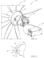
- the propulsion system 20 includes the propeller assembly 22 which includes a propeller 23 having the plurality of blades 24 and a power system 26, and a pump system 34, as shown in Fig. 2 .
- the power system 26 includes an electric motor 28 and a motor converter 30 that provides electrical power to the electric motor 28.
- the pump system 34 is mechanically coupled to the propeller 23 and to the electric motor 28 such that any one of the propeller assembly 22 and electric motor 28 can drive the pump system 34.
- the motor converter 30 In the event that the motor converter 30 exceeds a maximum tolerable temperature, the motor converter 30 will be shut down to prevent overheating. This excess temperature may be caused by a variety of factors, one of which is air bubbles in a coolant circuit 38 of the pump system 34 moving too slowly past a cooling plate 32 of the motor converter 30. In normal operating conditions, the pump system 34 is driven by the electric motor 28. As will be described in detail below, in the event the motor converter 30 overheats and shuts off, the propeller assembly 22 will drive the pump system 34 because of the mechanical connection between the propeller assembly 22 and the pump system 34. As a result, the pump system 34 continues to pump coolant through the cooling circuit 38 so as to move the air bubbles away from the cooling plate 32.
- Moving the air bubbles away from the cooling plate 32 allows the coolant fluid to continue removing heat from the cooling plate 32 efficiently to lower the temperature of the cooling plate 32, which subsequently lowers the temperature of the motor converter 30 such that it may be switched back on.
- the motor converter 30 may then resume supplying power to the electric motor 28 which may then power to the propeller 23.
- the propeller 23 includes the plurality of blades 24 which are configured to rotate about a central axis 25 and provide propulsive power to the aircraft 10.
- the plurality of blades 24 are arranged circumferentially around the axis central axis 25 and extend radially outward away from the central axis 25.
- the power system 26 includes the electric motor 28 and the motor converter 30 electrically connected to the electric motor 28, as shown in Fig. 2 .
- the electric motor 28 is mechanically coupled to the propeller assembly 22 so as to drive the blades 24 of the propeller 23.
- the electric motor 28 may be an electric motor known in the art that is utilized to convert supplied electrical energy into kinetic energy which is transferred to the blades 24 which rotate and provide propulsive power to the aircraft 10.
- the motor converter 30 is electrically connected to the electric motor 28 and configured to deliver electric power to the electric motor 28, as shown in Fig. 2 .
- the motor converter 30 and the electric motor 28 may be integrated into a single unit.
- the motor converter 30 may be an converter known in the art that is utilized to regulate power supplied to the electric motor 28.
- the motor converter 30 is arranged between a power supply and the electric motor 28, and is configured to receive power from the power supply and convert DC current to AC current, AC current to DC current, and AC current to AC current that subsequently flows to the electric motor 28.
- the motor converter 30 may regulate current returning from the motor to the power supply and/or modify the properties of the incoming and exiting current.
- the motor converter 30 may also adjust frequency and voltage of the power supplied to the electric motor 30 based on the current operating condition of the propulsion system 20.
- the motor converter 30 includes a plurality of converter switches 31 and a cooling plate 32, as shown in Fig. 2 .
- the converter switches 31 are configured to convert an incoming power supply of electrical energy for example from AC power to DC power and from DC power to AC power.
- the cooling plate 32 is thermally engaged with the converter switches 31 and is configured to remove heat from the converter switches 31 so as to cool the switches 31.
- the coolant circuit 38 is in thermal communication with the cooling plate 32 in order to remove heat from the cooling plate 32 which subsequently removes heat from the converter switches 31.
- the pump system 34 is configured to continue to pump coolant through the coolant circuit 38 so as to remove heat from the cooling plate 32 which subsequently removes heat from the converter switches 31 and allows the motor converter 30 to return to safe operating temperature.
- the pump system 34 includes a pump 36 and the coolant circuit 38 that runs from the pump 36 to the motor converter 30 and back to the pump 38 in a fluid circuit among other possible locations.
- the pump 36 is configured to pump coolant through the motor converter 30 via the coolant circuit 38 so as to cool the motor converter 30.
- the pump 36 is mechanically coupled to both the propeller assembly 22 and to the electric motor 28 such that rotation of any one of the propeller 23 and the electric motor 28 drives the pump 36, as shown in Figs. 2 and 3 .
- the pump 36 is mechanically connected to the electric motor 28 and the propeller 23 via a gearbox 46.
- the coolant circuit 38 includes a coolant that is configured to conduct heat away from the relevant components, including the cooling plate 32 of the motor converter 30.
- the coolant may be, but is not limited to, a water/ethylene glycol mixture or a water and propylene mixture.
- the pump 36 is configured to control the flow of coolant to be proportional to the rotational speed.
- the propulsion system 20 further includes the controller 42 connected to the power system 26, as shown in Fig. 2 .
- the power system 26, the converter 30, and the controller 42 may be integrated into a single unit.
- the controller 42 is configured to switch the power system 26 into the power-off arrangement in which the motor converter 30 is powered off and blocked from delivering the electric power to the electric motor 28 in response to a temperature of the motor converter 30 being greater than a predetermined threshold temperature. As discussed above, the temperature of the motor converter 30 may reach unsustainable levels in which the motor converter 30 must be shut down.
- This may be caused by a variety of factors, one of which is air bubbles that have accumulated throughout the coolant circuit 38 of the pump system 34 moving too slowly past the cooling plate 32 of the motor converter 30.
- the air bubbles flowing through the coolant circuit 38 may be caused by the aircraft 10 executing negative G maneuvers (negative gravity maneuvers).
- the controller 42 determines that the temperature of the motor converter 30, in particular the switches 31 of the motor converter 30, is too high (i.e. above the predetermined threshold temperature)
- the controller 42 will turn off the motor converter 30, in which the power system 26 is in the power-off arrangement.
- the electric motor 28 no longer receives power and does not power the propeller assembly 22.
- the blades 24 of the propeller 23 continue to rotate due to the ambient air continuing to flow over the blades 24, sometimes called windmilling.
- This rotation of the propeller 23 continues to drive the pump 36 such that coolant continues to move through the coolant circuit 38. This permits the coolant to continue to lower the temperature of the motor converter 30 to less than the threshold temperature, in which case the motor converter 30 may be turned back on and normal operation of the propulsion system 20 may resume.
- the controller 42 may be configured to determine that the temperature of the motor converter 30 has been lowered to below the threshold temperature. In response to determining that the temperature is below the threshold temperature, the controller 42 is configured to switch the power system 26 into a power-on arrangement in which the motor converter 30 is powered back on such that the pump 36 is driven by at least the electric motor 28 such that coolant continues to pump through the coolant circuit 38. In other embodiments, the controller 42 of the propulsion system 20 may generate an alert for a pilot of the aircraft 10 via an alert system indicating that the temperature of motor converter 30 has returned back below the threshold temperature, and the pilot may then manually power the motor converter 30 back on.
- the controller 42 may include at least one processor connected to a computer readable memory and/or other data storage.
- Computer executable instructions and data used by a processor may be stored in the computer readable memory included in an onboard computing device, a remote server, a combination of both, or implemented with any combination of read only memory modules or random access memory modules, optionally including both volatile and nonvolatile memory.
- the pump system 34 further includes an expansion tank 39 that is arranged in fluidic communication with the coolant circuit 38, as shown in Fig. 2 .
- the pump system 34 is configured to, in response to the air bubbles accumulating within the coolant circuit 38 and moving at a reduced speed past the cooling plate 32, move the air bubbles through the coolant circuit 38 away from the cooling plate 32 and into the expansion tank 39.
- the propulsion system 20 further includes the gearbox 46 mechanically coupled to the propeller 23 and to the pump system 34, as shown in Fig. 2 .
- the gearbox 46 is configured to transfer mechanical energy from the propeller 23 to the pump 36 of the pump system 34 so as to drive the pump in the event that the motor converter 30 is powered off.
- an accessory gearbox 46 is operably connected with the pump 36, the governor 50, and the motor 28.
- the motor 28 is directly connected to the propeller 23.
- a gearbox may be omitted, and the governor 150 is operably connected to the motor 128 which is directly connected to the propeller 123.
- the propeller assembly 22 further includes a propeller governor 50 configured to control a pitch angle of the plurality of blades 24 as shown in Figs. 2 and 4 .
- the propeller governor 50 may be any propeller governor known in the art that is utilized to regulate the rotational speed of the propeller 23 by moving fluid to and from the propeller which alters the pitch of the blades 24.
- the propeller governor 50 is configured to rotate the plurality of blades 24 of the propeller 23 from a first pitch angle to a second pitch angle different from the first pitch angle in response to the motor converter 30 being shut off.
- the propeller governor 50 may be configured to rotate the plurality of blades 24 to any pitch angle of 0 degrees to 180 degrees relative to the plane of rotation about the central axis 25.
- the propeller governor 50 may rotate the blades 24 to a positions 51, 52, 53, 54 which may be useful for various operating conditions of the aircraft.
- the governor 50 in response to the motor converter 30 overheating, adjusts the blade angle to allow for the propeller 23 to continue to rotate for a maximum amount of time, thus allowing for a maximum amount of time for the air bubbles to clear the cooling plate 32 and for the temperature of the motor converter 30, in particular the temperature of the converter switches 31, to return to below the threshold temperature.
- the propeller assembly 22 may include fixed pitch propeller blades 24 and thus would not utilize a propeller governor 50.
- the fixed propeller blades 24 could be utilized so long as the blades 24 allow the propeller 23 to continue to rotate after motor 30 shutdown for a long enough period of time to allow for the air bubbles to clear the coolant circuit 38.
- the motor converter 30 further includes at least one temperature sensor 60 located proximate to the plurality of converter switches 31 as shown in Fig. 2 .
- the temperature sensor 60 is configured to monitor a switch temperature of the plurality of converter switches 31 and relay the temperature to the controller 42 for execution of the above-described processes.
- the temperature of the motor converter 30 utilized by the controller 42 for determination of whether the motor converter 30 should be shut off is the switch temperature of the plurality of converter switches 31.
- the predetermined threshold temperature utilized by the controller 42 for determination of whether the motor converter 30 should be shut off is a predetermined threshold switch temperature of the plurality of converter switches 31.
- the predetermined threshold temperature of the plurality of converter switches 31 is 150 degrees Celsius.
- FIG. 6 Another embodiment of a propulsion system 120 which may be utilized in the aircraft 10 in accordance with the present disclosure is shown in Fig. 6 .
- the propulsion system 120 is substantially similar to the propulsion system 20 shown in Figs. 1-5 and described herein. Accordingly, similar reference numbers in the 100 series indicate features that are common between the propulsion system 120 and the propulsion system 20.
- the description of the propulsion system 20 also applies to the propulsion system 120, except in instances when it conflicts with the specific description and the drawings of the propulsion system 120.
- the propulsion system 120 includes a propeller assembly 122 that includes a propeller 123 having a plurality of blades 124 and configured to rotate around a central axis 125, and a power system 126, as shown in Fig. 6 .
- the power system 126 includes an electric first motor 128 mechanically coupled to the propeller 123 and configured to drive rotation of the propeller 123, and a motor converter 130 electrically connected to the electric first motor 128 and configured to deliver electric power to the electric first motor 128.
- the propulsion system 120 further includes a controller 142 connected to the power system 126 and configured to switch the power system into a power-off arrangement in which the motor converter 130 is powered off and blocked from delivering the electric power to the electric first motor 128, as shown in Fig. 6 .
- the controller 142 is configured to make the switch to the power-off arrangement in response to a temperature of the motor converter 130 being greater than a predetermined threshold temperature.
- the motor converter 130 includes a plurality of converter switches 131 and a cooling plate 132 engaged with the converter switches 131 so as to cool the switches 131.
- a temperature sensor 160 may be operably engaged with the converter switches 131 to monitor a temperature of the switches 131 and relay the temperature to the controller 142.
- the propulsion system 120 further includes a propeller governor 150.
- the propulsion system 120 further includes a pump system 134 including a pump 136 and a coolant circuit 138, as shown in Fig. 6 .
- the coolant circuit 138 is configured to remove heat from the motor converter 130.
- the pump 136 is configured to pump coolant through the coolant circuit 138, and is mechanically coupled to the propeller 123 and to the electric first motor 128 such that rotation of any one of the propeller 123 and the electric first motor 128 drives the pump 136.
- the pump system 134 may further include an expansion tank 139 in fluidic communication with the coolant circuit 138.
- the propulsion system 120 further includes a second motor 129 operably connected to the pump 136 and configured to drive the pump 136, as shown in Fig. 6 .
- the second motor 129 is powered independent of the motor converter 130 such that, in the event of a shutdown of the motor converter 130, the second motor 129 may be utilized to power the pump 136 along with the propeller 123 or by itself and without assistance from the propeller 123.
- the controller 142 in response to the motor converter 130 being shut down, the controller 142 is configured to instruct the second motor 129, which may already be operating, to continue to provide power to the pump 136 such that the pump 136 continues to function.
- the second motor 129 is an electric motor.
- the second motor 129 may be mechanically driven, for example, via a shaft and gearbox assembly.
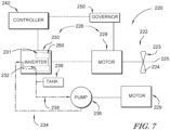
- FIG. 7 Another embodiment of a propulsion system 220 which may be utilized in the aircraft 10 in accordance with the present disclosure is shown in Fig. 7 .
- the propulsion system 220 is substantially similar to the propulsion systems 20, 120 shown in Figs. 1-6 and described herein. Accordingly, similar reference numbers in the 200 series indicate features that are common between the propulsion system 220 and the propulsion systems 20, 120.
- the description of the propulsion systems 20, 120 also apply to the propulsion system 220, except in instances when it conflicts with the specific description and the drawings of the propulsion system 220.
- the propulsion system 120 includes a propeller assembly 222 that includes a propeller 223 having a plurality of blades 224 and configured to rotate around a central axis 225, and a power system 226, as shown in Fig. 7 .
- the power system 226 includes an electric first motor 228 mechanically coupled to the propeller 223 and configured to drive rotation of the propeller 223, and a motor converter 230 electrically connected to the electric first motor 228 and configured to deliver electric power to the electric first motor 228.
- the propulsion system 220 further includes a controller 242 connected to the power system 226 and configured to switch the power system into a power-off arrangement in which the motor converter 230 is powered off and blocked from delivering the electric power to the electric first motor 228, as shown in Fig. 7 .
- the controller 242 is configured to make the switch to the power-off arrangement in response to a temperature of the motor converter 230 being greater than a predetermined threshold temperature.
- the motor converter 230 includes a plurality of converter switches 231 and a cooling plate 232 engaged with the converter switches 231 so as to cool the switches 231.
- a temperature sensor 260 may be operably engaged with the converter switches 231 to monitor a temperature of the switches 231 and relay the temperature to the controller 242.
- the propulsion system 120 further includes a propeller governor 250.
- the propulsion system 220 further includes a pump system 234 including a pump 236 and a coolant circuit 238, as shown in Fig. 7 .
- the coolant circuit 238 is configured to remove heat from the motor converter 230.
- the pump 236 is configured to pump coolant through the coolant circuit 238.
- the propulsion system 220 further includes a second motor 229 operably connected to the pump 236 and configured to drive the pump 236.
- the second motor 229 is powered independent of the motor converter 230 such that, in the event of a shutdown of the motor converter 230, the second motor 229 may be utilized to power the pump 236.
- the pump 236 is not connected to the motor 230 or the propeller 223 such that the second motor 229 is the only source of power for the pump 236.
- the controller 242 is configured to instruct the second motor 229, which may already be operating, to continue to provide power to the pump 236 such that the pump 236 continues to function.
- the second motor 129 is an electric motor.
- the second motor 229 may be mechanically driven, for example, via a shaft and gearbox assembly.
- a method includes a first operation of providing a propeller configured to rotate around a central axis and a power system, the power system including an electric motor and a motor converter.
- the method includes a second operation of mechanically coupling the electric motor to the propeller, the electric motor being configured to drive the propeller.
- the method includes a third operation of electrically connecting the motor converter to the electric motor.
- the method includes a fourth operation of providing a pump system including a pump and a coolant circuit.
- the method includes a fifth operation of mechanically coupling the pump to the propeller and to the electric motor such that at least one of the propeller and the electric motor drives the pump.
- the method includes a sixth operation of pumping, via the pump, coolant through the motor converter via the coolant circuit so as to cool the motor converter.
- the method includes a seventh operation of determining that a temperature of the motor converter is greater than a predetermined threshold temperature.
- the method includes an eighth operation of switching the power system into a power-off arrangement in which the electric motor and the motor converter are powered off.
- the method includes a ninth operation of driving the pump via only the propeller such that coolant continues to pump through the coolant circuit in order to lower the temperature of the motor converter to less than the predetermined threshold temperature during operation of the propulsion system.
- the method further includes an additional operation of determining that the temperature of the motor converter is less than the predetermined threshold temperature.
- the method may further include an additional operation of switching the power system into a power-on arrangement in which the motor converter is powered on.
- the method may further include an additional operation of driving the pump via at least the electric motor such that coolant continues to pump through the coolant circuit.
Landscapes
- Engineering & Computer Science (AREA)
- Mechanical Engineering (AREA)
- Aviation & Aerospace Engineering (AREA)
- Chemical & Material Sciences (AREA)
- General Engineering & Computer Science (AREA)
- Manufacturing & Machinery (AREA)
- Chemical Kinetics & Catalysis (AREA)
- Electrochemistry (AREA)
- General Chemical & Material Sciences (AREA)
- Combustion & Propulsion (AREA)
- Motor Or Generator Cooling System (AREA)
Claims (14)
- Ein Antriebssystem (20, 120, 220) für ein Flugzeug, das Antriebssystem (20, 120, 220) umfassend:eine Propelleranordnung (22, 122, 222), die einen Propeller (23, 123, 223), der dazu eingerichtet ist, sich um eine zentrale Achse (25) zu drehen, und ein Stromsystem (26, 126, 226) enthält, wobei das Stromsystem (26, 126, 226) einen Elektromotor (28), der mechanisch mit dem Propeller (23, 123, 223) gekoppelt und dazu eingerichtet ist, den Propeller (23, 123, 223) anzutreiben, und einen Motorkonverter (30, 130, 230) enthält, der elektrisch mit dem Elektromotor (28) verbunden und dazu eingerichtet ist, elektrische Energie an den Elektromotor (28) zu liefern,eine Steuerung (42, 142, 242), die mit dem Stromsystem (26, 126, 226) verbunden und dazu eingerichtet ist, das Stromsystem (26, 126, 226) in eine stromlose Anordnung zu schalten, in der der Motorkonverter (30, 130, 230) ausgeschaltet und daran gehindert ist, elektrische Energie an den Elektromotor (28) zu liefern, als Reaktion darauf, dass eine Temperatur des Motorkonverters (30, 130, 230) größer als eine vorbestimmte Schwellentemperatur ist, undein Pumpensystem (34, 134, 234), das eine Pumpe (36, 136, 236) und einen Kühlmittelkreislauf (38, 138, 238) enthält, wobei die Pumpe (36, 136, 236) dazu eingerichtet ist, Kühlmittel durch den Motorkonverter (30, 130, 230) über den Kühlmittelkreislauf (38, 138, 238) zu pumpen, um den Motorkonverter (30, 130, 230) zu kühlen,dadurch gekennzeichnet, dass die Pumpe (36, 136, 236) mechanisch mit dem Propeller (23, 123, 223) und dem Elektromotor (28) gekoppelt ist, so dass die Drehung des Propellers (23, 123, 223) oder des Elektromotors (28) die Pumpe (36, 136, 236) antreibt, so dass die Drehung des Propellers (23, 123, 223) die Pumpe (36, 136, 236) antreibt, um das Kühlmittel durch den Kühlmittelkreislauf (38, 138, 238) zu bewegen und die Temperatur des Motorkonverters (30, 130, 230) unter die vorbestimmte Schwellentemperatur zu senken, als Reaktion darauf, dass sich der Motorkonverter (30, 130, 230) während des Betriebs des Antriebssystems (20, 120, 220) in der stromlosen Anordnung befindet.
- Das Antriebssystem (20, 120, 220) nach Anspruch 1, wobei der Motorkonverter (30, 130, 230) eine Vielzahl von Konverterschaltern (31, 131, 231), die dazu eingerichtet sind, ein- und ausgehenden Strom zu regulieren, und eine Kühlplatte (32, 132, 232) enthält, die thermisch mit der Vielzahl von Konverterschaltern (31, 131, 231) in Eingriff steht und dazu eingerichtet ist, Wärme von der Vielzahl von Konverterschaltern (31, 131, 231) zu entfernen, wobei der Kühlmittelkreislauf (38, 138, 238) so angeordnet ist, dass er thermisch mit der Kühlplatte (32, 132, 232) in Eingriff steht, um Wärme von der Kühlplatte (32, 132, 232) zu entfernen, die anschließend Wärme von der Vielzahl von Konverterschaltern (31, 131, 231) entfernt, und wobei als Reaktion darauf, dass sich das Stromsystem (26, 126, 226) in der stromlosen Anordnung befindet, das Pumpensystem (34, 134, 234) dazu eingerichtet ist, das Kühlmittel durch den Kühlmittelkreislauf (38, 138, 238) zu pumpen, um Wärme von der Kühlplatte (32, 132, 232) zu entfernen, die anschließend Wärme von der Vielzahl von Konverterschaltern (31, 131, 231) entfernt.
- Das Antriebssystem (20, 120, 220) nach Anspruch 2, wobei das Pumpensystem (34, 134, 234) ferner einen Ausdehnungsbehälter (39) in Fluidverbindung mit dem Kühlmittelkreislauf (38, 138, 238) enthält und wobei das Pumpensystem (34, 134, 234) dazu eingerichtet ist, als Reaktion darauf, dass sich Luftblasen im Kühlmittelkreislauf (38, 138, 238) ansammeln und sich mit einer reduzierten Geschwindigkeit an der Kühlplatte (32, 132, 232) vorbeibewegen, die Luftblasen durch den Kühlmittelkreislauf (38, 138, 238) von der Kühlplatte (32, 132, 232) weg und in den Ausdehnungsbehälter (39) zu bewegen.
- Das Antriebssystem (20, 120, 220) nach Anspruch 3, wobei der Motorkonverter (30, 130, 230) ferner mindestens einen Temperatursensor (60, 160, 260) umfasst, der in der Nähe der Vielzahl von Konverterschaltern (31, 131, 231) angeordnet ist, um eine Temperatur der Vielzahl von Konverterschaltern (31, 131, 231) zu überwachen.
- Das Antriebssystem (20, 120, 220) nach Anspruch 4, wobei die Temperatur des Motorkonverters (30, 130, 230), die von der Steuerung (42, 142, 242) verwendet wird, die Temperatur der Vielzahl von Konverterschaltern (31, 131, 231) ist, und wobei die von der Steuerung (42, 142, 242) verwendete vorbestimmte Schwellentemperatur eine vorbestimmte Schwellentemperatur der Vielzahl von Konverterschaltern (31, 131, 231) ist.
- Das Antriebssystem (20, 120, 220) nach Anspruch 5, wobei die vorbestimmte Schwellentemperatur der Vielzahl von Konverterschaltern (31, 131, 231) 150 Grad Celsius beträgt.
- Das Antriebssystem (20, 120, 220) nach einem der vorhergehenden Ansprüche, wobei der Propeller (23, 123, 223) eine Vielzahl von Blättern (24, 124, 224) enthält und die Propelleranordnung (22, 122, 222) ferner einen Propellerregler (50, 150, 250) enthält, der dazu eingerichtet ist, einen Anstellwinkel der Vielzahl an Blättern (24, 124, 224) zu steuern, wobei der Propellerregler (50, 150, 250) als Reaktion auf die Steuerung (42, 142, 242), die das Stromsystem (26, 126, 226) in die stromlose Anordnung schaltet, dazu eingerichtet ist, den Anstellwinkel der Vielzahl von Blättern (24, 124, 224) des Propellers (23, 123, 223) von einem ersten Anstellwinkel zu einem zweiten Anstellwinkel zu ändern, der sich von dem ersten Anstellwinkel unterscheidet.
- Das Antriebssystem (20, 120, 220) nach Anspruch 7, wobei der zweite Anstellwinkel es dem Propeller (23, 123, 223) ermöglicht, sich in der stromlosen Anordnung mit einer maximalen Drehzahl weiterzudrehen, um die Pumpe (36, 136, 236) für eine maximale Zeitspanne weiter anzutreiben.
- Das Antriebssystem (20, 120, 220) nach einem der vorhergehenden Ansprüche, ferner umfassend:
ein Getriebe (46), das mechanisch mit dem Propeller (23, 123, 223) und dem Pumpensystem (34, 134, 234) gekoppelt ist, und das Getriebe (46) ist dazu eingerichtet, mechanische Energie vom Propeller (23, 123, 223) auf die Pumpe (36, 136, 236) des Pumpensystems (34, 134, 234) zu übertragen, um die Pumpe (36, 136, 236) anzutreiben. - Das Antriebssystem (20, 120, 220) nach einem der vorhergehenden Ansprüche, wobei das Kühlmittel ein Gemisch aus Wasser und Ethylenglykol oder ein Gemisch aus Wasser und Propylen ist.
- Das Antriebssystem (20, 120, 220) nach einem der vorhergehenden Ansprüche, wobei die Pumpe (36, 136, 236) eine Verdrängerpumpe ist, die dazu eingerichtet ist, als Reaktion auf eine konstante Drehzahl des Propellers (23, 123, 223) einen konstanten Kühlmittelfluss bereitzustellen.
- Das Antriebssystem (20, 120, 220) nach einem der vorhergehenden Ansprüche, wobei das Stromsystem (26, 126, 226) ferner einen zweiten Motor (129, 229) enthält, der mit der Pumpe (36, 136, 236) in Wirkverbindung steht und dazu eingerichtet ist, die Pumpe (36, 136, 236) anzutreiben, und wobei der zweite Motor (129, 229) unabhängig vom Motorkonverter (30, 130, 230) angetrieben wird.
- Ein Verfahren umfassendBereitstellen einer Propelleranordnung (22, 122, 222), die einen Propeller (23, 123, 223) und ein Stromsystem (26, 126, 226) enthält, wobei der Propeller (23, 123, 223) dazu eingerichtet ist, sich um eine zentrale Achse (25) zu drehen, wobei das Stromsystem (26, 126, 226) einen Elektromotor (28) und einen Motorkonverter (30, 130, 230) enthält,Mechanisches Koppeln des Elektromotors (28) mit dem Propeller (23, 123, 223), wobei der Elektromotor (28) dazu eingerichtet ist, den Propeller (23, 123, 223) anzutreiben,den Motorkonverter (30, 130, 230) elektrisch mit dem Elektromotor (28) verbindet,Bereitstellen eines Pumpensystems (34, 134, 234), das eine Pumpe (36, 136, 236) und einen Kühlmittelkreislauf (38, 138, 238) enthält,Mechanisches Koppeln der Pumpe (36, 136, 236) mit dem Propeller (23, 123, 223) und dem Elektromotor (28), so dass mindestens einer des Propellers (23, 123, 223) und des Elektromotors (28) die Pumpe (36, 136, 236) antreibt,Pumpen, über die Pumpe (36, 136, 236), von Kühlmittel durch den Motorkonverter (30, 130, 230) über den Kühlmittelkreislauf (38, 138, 238), um den Motorkonverter (30, 130, 230) zu kühlen,Bestimmen, dass eine Temperatur des Motorkonverters (30, 130, 230) größer als eine vorbestimmte Schwellentemperatur ist,Schalten des Stromsystems (26, 126, 226) in eine stromlose Anordnung, in der der Elektromotor (28) und der Motorkonverter (30, 130, 230) ausgeschaltet sind, unddadurch gekennzeichnet, dass das Verfahren ferner den folgenden Schritt umfasst:
Antreiben der Pumpe (36, 136, 236) nur über den Propeller (23, 123, 223), so dass das Kühlmittel weiterhin durch den Kühlmittelkreislauf (38, 138, 238) gepumpt wird, um die Temperatur des Motorkonverters (30, 130, 230) während des Betriebs des Antriebssystems (20, 120, 220) unter die vorbestimmte Schwellentemperatur zu senken. - Das Verfahren nach Anspruch 13, ferner umfassend:Bestimmen, dass die Temperatur des Motorkonverters (30, 130, 230) geringer ist als die vorbestimmte Schwellentemperatur,Schalten des Stromsystems (26, 126, 226) in eine eingeschaltete Anordnung, in der der Motorkonverter (30, 130, 230) eingeschaltet ist, undAntreiben der Pumpe (36, 136, 236) über mindestens den Elektromotor (28), so dass das Kühlmittel weiterhin durch den Kühlmittelkreislauf (38, 138, 238) gepumpt wird.
Applications Claiming Priority (1)
| Application Number | Priority Date | Filing Date | Title |
|---|---|---|---|
| US17/553,756 US12024308B2 (en) | 2021-12-16 | 2021-12-16 | Propeller driven backup cooling pump system for electric motor converter |
Publications (2)
| Publication Number | Publication Date |
|---|---|
| EP4197915A1 EP4197915A1 (de) | 2023-06-21 |
| EP4197915B1 true EP4197915B1 (de) | 2025-04-09 |
Family
ID=83899576
Family Applications (1)
| Application Number | Title | Priority Date | Filing Date |
|---|---|---|---|
| EP22202438.2A Active EP4197915B1 (de) | 2021-12-16 | 2022-10-19 | Propellerbetriebenes notkühlpumpensystem für elektromotorumrichter |
Country Status (2)
| Country | Link |
|---|---|
| US (1) | US12024308B2 (de) |
| EP (1) | EP4197915B1 (de) |
Families Citing this family (1)
| Publication number | Priority date | Publication date | Assignee | Title |
|---|---|---|---|---|
| US12332659B2 (en) * | 2022-04-29 | 2025-06-17 | Beta Air Llc | System for propeller parking control for an electric aircraft and a method for its use |
Family Cites Families (13)
| Publication number | Priority date | Publication date | Assignee | Title |
|---|---|---|---|---|
| US5105875A (en) | 1991-01-10 | 1992-04-21 | Sundstrand Corporation | Cooling system for auxiliary power unit |
| US5271248A (en) * | 1991-08-23 | 1993-12-21 | Sundstrand Corporation | Dual cooling system |
| US8424285B2 (en) | 2009-07-31 | 2013-04-23 | Hamilton Sundstrand Corporation | Cooling system for electronic device in a gas turbine engine system |
| JP5440877B2 (ja) * | 2010-12-27 | 2014-03-12 | 株式会社デンソー | インバータ制御装置,インバータ制御方法および車両 |
| EP2774853A1 (de) * | 2013-03-07 | 2014-09-10 | Siemens Aktiengesellschaft | Antriebsgondel für ein Flugzeug |
| US20170081040A1 (en) | 2015-09-21 | 2017-03-23 | Hamilton Sundstrand Corporation | Heat exchanger and cooling system for generator electronics cooling |
| US10995656B2 (en) | 2017-08-17 | 2021-05-04 | Rolls-Royce North American Technologies Inc. | Supplement thermal management system cooling using thermoelectric cooling |
| GB201718141D0 (en) | 2017-11-02 | 2017-12-20 | Rolls Royce Plc | Thermal management system |
| JP6919546B2 (ja) * | 2017-12-13 | 2021-08-18 | トヨタ自動車株式会社 | 車両用電源システム |
| US11143113B2 (en) | 2019-02-27 | 2021-10-12 | Rolls-Royce Corporation | Hybrid gas turbine engine control system |
| WO2020219747A2 (en) | 2019-04-23 | 2020-10-29 | Joby Aero, Inc. | Battery thermal management system and method |
| JP6827519B1 (ja) * | 2019-12-18 | 2021-02-10 | 三菱電機株式会社 | 電力変換装置 |
| US11128251B1 (en) * | 2020-04-29 | 2021-09-21 | The Boeing Company | Fault-tolerant power system architecture for aircraft electric propulsion |
-
2021
- 2021-12-16 US US17/553,756 patent/US12024308B2/en active Active
-
2022
- 2022-10-19 EP EP22202438.2A patent/EP4197915B1/de active Active
Also Published As
| Publication number | Publication date |
|---|---|
| EP4197915A1 (de) | 2023-06-21 |
| US12024308B2 (en) | 2024-07-02 |
| US20230192309A1 (en) | 2023-06-22 |
Similar Documents
| Publication | Publication Date | Title |
|---|---|---|
| EP3670349B1 (de) | Motorgetriebener antrieb eines flugzeugs | |
| US12068707B2 (en) | Inverter circuits and electrical propulsion systems for eVTOL aircraft | |
| US9975619B1 (en) | PCM controlled charging system | |
| EP3798129A1 (de) | Elektromotor für einen propellerantrieb | |
| EP3798119A1 (de) | Antriebssystem für gegenläufig rotierende teile | |
| US12291996B2 (en) | Energy storage system heater control methods | |
| US20240069527A1 (en) | Aircraft thermal management system for an energy storage system | |
| EP4197915B1 (de) | Propellerbetriebenes notkühlpumpensystem für elektromotorumrichter | |
| US12434599B2 (en) | Aircraft having cooling circuits independent of each other | |
| EP4148253B1 (de) | Redundantes elektrisch angetriebenes brennstoff- und ölpumpensystem für gasturbinen mit bidirektionalem pumpenmotor | |
| EP3866235A1 (de) | Elektrisches erzeugungssystem mit einer brennstoffzelle und einem wärmeregulierungssystem | |
| CN114658550B (zh) | 燃气轮机系统 | |
| KR102004123B1 (ko) | 직렬 하이브리드 전력 장치 및 운용 방법 | |
| EP3845464B1 (de) | Doppelspannungs-niederdruckgenerator | |
| US9771164B2 (en) | Electric system architecture included in a more-electric engine (MEE) system | |
| EP4467464B1 (de) | Steuervorrichtung für ein elektrisches flugzeug | |
| CN116805737A (zh) | 温度控制系统、温度控制方法和航空器 | |
| CN110398169B (zh) | 轨道车辆的换热系统和轨道车辆的换热系统的控制策略 | |
| JP7580355B2 (ja) | 航空機の推進システム | |
| JP2021090315A (ja) | エンジン駆動式発電装置 | |
| CN113412219A (zh) | 飞机推进系统 | |
| JP7505477B2 (ja) | 電動飛行体の制御装置及び制御プログラム | |
| EP4703271A1 (de) | Antriebsanordnung für ein elektrisches flugzeug | |
| CN120664117A (zh) | 用于混合动力电动系统的容错热管理系统 | |
| WO2024237024A1 (ja) | 推進システム |
Legal Events
| Date | Code | Title | Description |
|---|---|---|---|
| PUAI | Public reference made under article 153(3) epc to a published international application that has entered the european phase |
Free format text: ORIGINAL CODE: 0009012 |
|
| STAA | Information on the status of an ep patent application or granted ep patent |
Free format text: STATUS: THE APPLICATION HAS BEEN PUBLISHED |
|
| AK | Designated contracting states |
Kind code of ref document: A1 Designated state(s): AL AT BE BG CH CY CZ DE DK EE ES FI FR GB GR HR HU IE IS IT LI LT LU LV MC ME MK MT NL NO PL PT RO RS SE SI SK SM TR |
|
| STAA | Information on the status of an ep patent application or granted ep patent |
Free format text: STATUS: REQUEST FOR EXAMINATION WAS MADE |
|
| 17P | Request for examination filed |
Effective date: 20231213 |
|
| RBV | Designated contracting states (corrected) |
Designated state(s): AL AT BE BG CH CY CZ DE DK EE ES FI FR GB GR HR HU IE IS IT LI LT LU LV MC ME MK MT NL NO PL PT RO RS SE SI SK SM TR |
|
| GRAP | Despatch of communication of intention to grant a patent |
Free format text: ORIGINAL CODE: EPIDOSNIGR1 |
|
| STAA | Information on the status of an ep patent application or granted ep patent |
Free format text: STATUS: GRANT OF PATENT IS INTENDED |
|
| INTG | Intention to grant announced |
Effective date: 20241017 |
|
| P01 | Opt-out of the competence of the unified patent court (upc) registered |
Free format text: CASE NUMBER: APP_62015/2024 Effective date: 20241120 |
|
| GRAS | Grant fee paid |
Free format text: ORIGINAL CODE: EPIDOSNIGR3 |
|
| GRAA | (expected) grant |
Free format text: ORIGINAL CODE: 0009210 |
|
| STAA | Information on the status of an ep patent application or granted ep patent |
Free format text: STATUS: THE PATENT HAS BEEN GRANTED |
|
| AK | Designated contracting states |
Kind code of ref document: B1 Designated state(s): AL AT BE BG CH CY CZ DE DK EE ES FI FR GB GR HR HU IE IS IT LI LT LU LV MC ME MK MT NL NO PL PT RO RS SE SI SK SM TR |
|
| REG | Reference to a national code |
Ref country code: GB Ref legal event code: FG4D |
|
| REG | Reference to a national code |
Ref country code: CH Ref legal event code: EP |
|
| REG | Reference to a national code |
Ref country code: DE Ref legal event code: R096 Ref document number: 602022012846 Country of ref document: DE |
|
| REG | Reference to a national code |
Ref country code: IE Ref legal event code: FG4D |
|
| REG | Reference to a national code |
Ref country code: NL Ref legal event code: MP Effective date: 20250409 |
|
| PG25 | Lapsed in a contracting state [announced via postgrant information from national office to epo] |
Ref country code: NL Free format text: LAPSE BECAUSE OF FAILURE TO SUBMIT A TRANSLATION OF THE DESCRIPTION OR TO PAY THE FEE WITHIN THE PRESCRIBED TIME-LIMIT Effective date: 20250409 |
|
| REG | Reference to a national code |
Ref country code: AT Ref legal event code: MK05 Ref document number: 1783350 Country of ref document: AT Kind code of ref document: T Effective date: 20250409 |
|
| PG25 | Lapsed in a contracting state [announced via postgrant information from national office to epo] |
Ref country code: FI Free format text: LAPSE BECAUSE OF FAILURE TO SUBMIT A TRANSLATION OF THE DESCRIPTION OR TO PAY THE FEE WITHIN THE PRESCRIBED TIME-LIMIT Effective date: 20250409 Ref country code: ES Free format text: LAPSE BECAUSE OF FAILURE TO SUBMIT A TRANSLATION OF THE DESCRIPTION OR TO PAY THE FEE WITHIN THE PRESCRIBED TIME-LIMIT Effective date: 20250409 Ref country code: PT Free format text: LAPSE BECAUSE OF FAILURE TO SUBMIT A TRANSLATION OF THE DESCRIPTION OR TO PAY THE FEE WITHIN THE PRESCRIBED TIME-LIMIT Effective date: 20250811 |
|
| REG | Reference to a national code |
Ref country code: LT Ref legal event code: MG9D |
|
| PG25 | Lapsed in a contracting state [announced via postgrant information from national office to epo] |
Ref country code: NO Free format text: LAPSE BECAUSE OF FAILURE TO SUBMIT A TRANSLATION OF THE DESCRIPTION OR TO PAY THE FEE WITHIN THE PRESCRIBED TIME-LIMIT Effective date: 20250709 Ref country code: GR Free format text: LAPSE BECAUSE OF FAILURE TO SUBMIT A TRANSLATION OF THE DESCRIPTION OR TO PAY THE FEE WITHIN THE PRESCRIBED TIME-LIMIT Effective date: 20250710 |
|
| PG25 | Lapsed in a contracting state [announced via postgrant information from national office to epo] |
Ref country code: PL Free format text: LAPSE BECAUSE OF FAILURE TO SUBMIT A TRANSLATION OF THE DESCRIPTION OR TO PAY THE FEE WITHIN THE PRESCRIBED TIME-LIMIT Effective date: 20250409 |
|
| PG25 | Lapsed in a contracting state [announced via postgrant information from national office to epo] |
Ref country code: BG Free format text: LAPSE BECAUSE OF FAILURE TO SUBMIT A TRANSLATION OF THE DESCRIPTION OR TO PAY THE FEE WITHIN THE PRESCRIBED TIME-LIMIT Effective date: 20250409 |
|
| PG25 | Lapsed in a contracting state [announced via postgrant information from national office to epo] |
Ref country code: HR Free format text: LAPSE BECAUSE OF FAILURE TO SUBMIT A TRANSLATION OF THE DESCRIPTION OR TO PAY THE FEE WITHIN THE PRESCRIBED TIME-LIMIT Effective date: 20250409 |
|
| PG25 | Lapsed in a contracting state [announced via postgrant information from national office to epo] |
Ref country code: AT Free format text: LAPSE BECAUSE OF FAILURE TO SUBMIT A TRANSLATION OF THE DESCRIPTION OR TO PAY THE FEE WITHIN THE PRESCRIBED TIME-LIMIT Effective date: 20250409 |
|
| PG25 | Lapsed in a contracting state [announced via postgrant information from national office to epo] |
Ref country code: RS Free format text: LAPSE BECAUSE OF FAILURE TO SUBMIT A TRANSLATION OF THE DESCRIPTION OR TO PAY THE FEE WITHIN THE PRESCRIBED TIME-LIMIT Effective date: 20250709 |
|
| PG25 | Lapsed in a contracting state [announced via postgrant information from national office to epo] |
Ref country code: IS Free format text: LAPSE BECAUSE OF FAILURE TO SUBMIT A TRANSLATION OF THE DESCRIPTION OR TO PAY THE FEE WITHIN THE PRESCRIBED TIME-LIMIT Effective date: 20250809 |
|
| PG25 | Lapsed in a contracting state [announced via postgrant information from national office to epo] |
Ref country code: LV Free format text: LAPSE BECAUSE OF FAILURE TO SUBMIT A TRANSLATION OF THE DESCRIPTION OR TO PAY THE FEE WITHIN THE PRESCRIBED TIME-LIMIT Effective date: 20250409 |
|
| PGFP | Annual fee paid to national office [announced via postgrant information from national office to epo] |
Ref country code: DE Payment date: 20251028 Year of fee payment: 4 |
|
| REG | Reference to a national code |
Ref country code: DE Ref legal event code: R097 Ref document number: 602022012846 Country of ref document: DE |
|
| PG25 | Lapsed in a contracting state [announced via postgrant information from national office to epo] |
Ref country code: SM Free format text: LAPSE BECAUSE OF FAILURE TO SUBMIT A TRANSLATION OF THE DESCRIPTION OR TO PAY THE FEE WITHIN THE PRESCRIBED TIME-LIMIT Effective date: 20250409 Ref country code: DK Free format text: LAPSE BECAUSE OF FAILURE TO SUBMIT A TRANSLATION OF THE DESCRIPTION OR TO PAY THE FEE WITHIN THE PRESCRIBED TIME-LIMIT Effective date: 20250409 |
|
| PG25 | Lapsed in a contracting state [announced via postgrant information from national office to epo] |
Ref country code: CZ Free format text: LAPSE BECAUSE OF FAILURE TO SUBMIT A TRANSLATION OF THE DESCRIPTION OR TO PAY THE FEE WITHIN THE PRESCRIBED TIME-LIMIT Effective date: 20250409 |
|
| PG25 | Lapsed in a contracting state [announced via postgrant information from national office to epo] |
Ref country code: EE Free format text: LAPSE BECAUSE OF FAILURE TO SUBMIT A TRANSLATION OF THE DESCRIPTION OR TO PAY THE FEE WITHIN THE PRESCRIBED TIME-LIMIT Effective date: 20250409 |
|
| PG25 | Lapsed in a contracting state [announced via postgrant information from national office to epo] |
Ref country code: SK Free format text: LAPSE BECAUSE OF FAILURE TO SUBMIT A TRANSLATION OF THE DESCRIPTION OR TO PAY THE FEE WITHIN THE PRESCRIBED TIME-LIMIT Effective date: 20250409 |
|
| PG25 | Lapsed in a contracting state [announced via postgrant information from national office to epo] |
Ref country code: IT Free format text: LAPSE BECAUSE OF FAILURE TO SUBMIT A TRANSLATION OF THE DESCRIPTION OR TO PAY THE FEE WITHIN THE PRESCRIBED TIME-LIMIT Effective date: 20250409 |
|
| PLBE | No opposition filed within time limit |
Free format text: ORIGINAL CODE: 0009261 |
|
| STAA | Information on the status of an ep patent application or granted ep patent |
Free format text: STATUS: NO OPPOSITION FILED WITHIN TIME LIMIT |
|
| REG | Reference to a national code |
Ref country code: CH Ref legal event code: L10 Free format text: ST27 STATUS EVENT CODE: U-0-0-L10-L00 (AS PROVIDED BY THE NATIONAL OFFICE) Effective date: 20260218 |
|
| PG25 | Lapsed in a contracting state [announced via postgrant information from national office to epo] |
Ref country code: RO Free format text: LAPSE BECAUSE OF FAILURE TO SUBMIT A TRANSLATION OF THE DESCRIPTION OR TO PAY THE FEE WITHIN THE PRESCRIBED TIME-LIMIT Effective date: 20250409 |
|
| 26N | No opposition filed |
Effective date: 20260112 |