EP4197909B1 - Vorrichtung zur befestigung von menschlicher und/oder nicht-menschlicher fracht zur verwendung mit einem drehflügler - Google Patents
Vorrichtung zur befestigung von menschlicher und/oder nicht-menschlicher fracht zur verwendung mit einem drehflügler Download PDFInfo
- Publication number
- EP4197909B1 EP4197909B1 EP21400024.2A EP21400024A EP4197909B1 EP 4197909 B1 EP4197909 B1 EP 4197909B1 EP 21400024 A EP21400024 A EP 21400024A EP 4197909 B1 EP4197909 B1 EP 4197909B1
- Authority
- EP
- European Patent Office
- Prior art keywords
- human
- body section
- attachment
- rotatable attachment
- lateral
- Prior art date
- Legal status (The legal status is an assumption and is not a legal conclusion. Google has not performed a legal analysis and makes no representation as to the accuracy of the status listed.)
- Active
Links
Images
Classifications
-
- B—PERFORMING OPERATIONS; TRANSPORTING
- B66—HOISTING; LIFTING; HAULING
- B66C—CRANES; LOAD-ENGAGING ELEMENTS OR DEVICES FOR CRANES, CAPSTANS, WINCHES, OR TACKLES
- B66C1/00—Load-engaging elements or devices attached to lifting or lowering gear of cranes or adapted for connection therewith for transmitting lifting forces to articles or groups of articles
- B66C1/10—Load-engaging elements or devices attached to lifting or lowering gear of cranes or adapted for connection therewith for transmitting lifting forces to articles or groups of articles by mechanical means
- B66C1/22—Rigid members, e.g. L-shaped members, with parts engaging the under surface of the loads; Crane hooks
- B66C1/34—Crane hooks
- B66C1/36—Crane hooks with means, e.g. spring-biased detents, for preventing inadvertent disengagement of loads
-
- B—PERFORMING OPERATIONS; TRANSPORTING
- B64—AIRCRAFT; AVIATION; COSMONAUTICS
- B64D—EQUIPMENT FOR FITTING IN OR TO AIRCRAFT; FLIGHT SUITS; PARACHUTES; ARRANGEMENT OR MOUNTING OF POWER PLANTS OR PROPULSION TRANSMISSIONS IN AIRCRAFT
- B64D1/00—Dropping, ejecting, releasing or receiving articles, liquids, or the like, in flight
- B64D1/02—Dropping, ejecting, or releasing articles
- B64D1/08—Dropping, ejecting, or releasing articles the articles being load-carrying devices
- B64D1/12—Releasing
-
- B—PERFORMING OPERATIONS; TRANSPORTING
- B64—AIRCRAFT; AVIATION; COSMONAUTICS
- B64D—EQUIPMENT FOR FITTING IN OR TO AIRCRAFT; FLIGHT SUITS; PARACHUTES; ARRANGEMENT OR MOUNTING OF POWER PLANTS OR PROPULSION TRANSMISSIONS IN AIRCRAFT
- B64D1/00—Dropping, ejecting, releasing or receiving articles, liquids, or the like, in flight
- B64D1/22—Taking-up articles from earth's surface
-
- B—PERFORMING OPERATIONS; TRANSPORTING
- B64—AIRCRAFT; AVIATION; COSMONAUTICS
- B64C—AEROPLANES; HELICOPTERS
- B64C27/00—Rotorcraft; Rotors peculiar thereto
Definitions
- the present invention is related to a human and/or non-human cargo attachment device for use with a rotorcraft, which is embodied to permit transport of human and/or non-human external cargo outside of the rotorcraft.
- Non-human cargo attachment devices for use with a rotorcraft which are embodied to permit transport of non-human external cargo outside of the rotorcraft, may be provided in the form of hooks that are attached to ropes or cables which are connected to the rotorcraft.
- Such hooks may be embodied as simple hooks, safety hooks, snap hooks, or even more complicated forms of hooks.
- the document EP 3 781 480 A1 describes a perforated capsule hook with a perforated housing which is attachable to non-human external cargo and remains after retraction from the non-human external cargo in a comparatively stable state during high speed flight due to a plurality of holes and perforations provided in the perforated housing.
- human and/or non-human cargo attachment devices for use with a rotorcraft which are embodied to permit transport of human and/or non-human external cargo outside of the rotorcraft, are available in a wide range of variations and usually attachable to ropes or cables which are connected to the rotorcraft.
- ropes or cables with human and/or non-human cargo attachment devices may e. g. be used for rapidly inserting and/or extracting persons and/or cargo into/from various environments, in particular environments that do not permit landing of the rotorcraft.
- environments may e. g. include maritime environments such as offshore as well as oil and gas platforms, and terrestrial environments such as land in vegetated areas, mountains and urban territory.
- rigging plates or loops of so-called SPIE S pecial P atrol I nsertion/ E xtraction
- SPIE S pecial P atrol I nsertion/ E xtraction
- personal transport nets personal transport platforms, all of which are attachable to associated attachment interfaces such as safety hooks or snap hooks provided at associated ropes or cables of a given rotorcraft.
- the rigging plates or loops may be distributed over the length of associated ropes in order to form lashing points for attachment of human or non-human cargo.
- the documents CN 112 047 228 A , CN 205 114 816 U , EP 3 037 133 B1 , GB 2 340 101 B , and US 1,408,940 A describe illustrative ropes with rigging plates or loops that form lashing points.
- Other rigging plates which are configured to provide multiple lashing points and which are attachable to attachment interfaces provided at associated ropes or cables are e. g. described in the documents US 2021/0047149 A1 , US 10,398,939 B1 , and US 6,336,260 B1 .
- CN108673550 discloses a manipulator device suspended by a rope for installing on a drone.
- US2016368605 discloses a rope suspension device with at least one rope suspension module that is adapted for suspension of at least one rope from a rotorcraft and US5836548 discloses an airframe for selectively attaching and releasing multiple payloads suspended by a cable from an aircraft.
- helicopter under-slung load equipment nets are well-known and widely used for transporting goods by helicopter either when there is no room in the helicopter for the goods, or when for reasons of speed or efficiency it is preferred to keep the goods outside of the helicopter.
- helicopter under-slung load equipment nets usually consist of a braided nylon net body and a plurality of lifting loops made from nylon webbing.
- each net usually comprises four pairs of lifting loops and each pair of lifting loops is provided with a hook.
- EP 1 100 720 A1 describes a personal transport platform that may be suspended from a rotorcraft for rescuing people or equipment and that forms a link between the rotorcraft and a pod capable of being folded and unfolded, which is formed by a frame associated with a flexible support, such as a net.
- the frame comprises, fixed to the link, a central mast connected to mobile means bearing the flexible support, for folding and unfolding the mobile means and the flexible support about the central mast.
- none of the above-described human and/or non-human cargo attachment devices is suitable for use with a rotorcraft for inserting and/or extracting persons and/or cargo into/from forested areas.
- an object of the present invention to provide a new human and/or non-human cargo attachment device which is suitable for use with a rotorcraft for inserting and/or extracting persons and/or cargo into/from forested areas.
- a human and/or non-human cargo attachment device for use with a rotorcraft which comprises the features of claim 1. More specifically, according to the present invention a human and/or non-human cargo attachment device for use with a rotorcraft comprises a mounting interface with a carrier device and an attachment that is rigidly mounted to the carrier device for attachment to a rotorcraft rope or cable, and a device body that is mounted to the carrier device and that comprises a stationary body section and a movable body section.
- the stationary body section is stationarily arranged on the carrier device and comprises a plurality of rotatable attachment hooks for attachment of human or non-human external cargo, wherein attached human or non-human external cargo is locked on the device body in closed state of the plurality of rotatable attachment hooks and releasable from the device body in opened state of the plurality of rotatable attachment hooks.
- the movable body section is movably arranged on the carrier device for enabling movements of the movable body section relative to the stationary body section between a locking position and a release position, wherein the plurality of rotatable attachment hooks is rotatable from the closed state to the opened state via movement of the movable body section from the locking position to the release position, and wherein the plurality of rotatable attachment hooks is rotatable from the opened state to the closed state via movement of the movable body section from the release position to the locking position.
- the inventive human and/or non-human cargo attachment device is suitable for use with a rotorcraft in forested areas and enables a fast and simple insertion/extraction of up to ten or even more persons into/from such forested areas, as well as any other potential application environment.
- a safe and secure use in forested areas is amongst others enabled by forming a respective device body of the human and/or non-human cargo attachment device with a dedicated penetrating design, preferably with an arrowhead shape.
- the device body is lightweight and weighs only approximately 7 kg while allowing at least transportation of up to ten persons, each having a weight of up to 150 kg. More specifically, the device body forms a single, compact and central point for insertion/extraction, which allows for interaction of transported persons during transportation. In particular, lifting and drop-off of transported persons and/or cargo in a single step is enabled. Furthermore, the device body is preferably embodied with a redundant design and provides for each rotatable attachment hook at least one additional lashing point for attachment of human external cargo.
- a required floatability of the star-shaped device body may be improved by filling its interior with foam.
- additional floats can be attached to the star-shaped device body, e. g. at selected rotatable attachment hooks. More specifically, any interior chambers of the device body may be filled with foam to achieve an increased floatability which is required to enable application in sea insertion/extraction.
- the human and/or non-human cargo attachment device comprises a star-shaped device body with e. g. ten rotatable attachment hooks, each forming a respective main lashing point for attachment of human or non-human external cargo.
- Each such main lashing point may be associated with a redundant lashing point with enough distance between them in order to avoid snap hook respectively carabiner interactions.
- the e. g. ten main lashing points, i. e. the rotatable attachment hooks are preferably provided at lateral support arms of the device body in order to transmit occurring lateral loads.
- the star-shaped device body exhibits an arrowhead form in order to be able to penetrate e. g. through trees in forested areas.
- the star-shaped device body may preferably be attached to a rope or cable of a rotorcraft by means of a suitable load hook.
- the rotatable attachment hooks of the star-shaped device body may be opened or closed either all at the same time or in at least two separate groups, e. g. in two groups of five rotatable attachment hooks.
- the opening of the rotatable attachment hooks of each such group is preferably initiated by a movement of a respectively associated movable body section away from the stationary body section into a release position. In locking position of the respectively associated movable body section, the latter preferably forms a form-fit locking with the rotatable attachment hooks, e. g.
- the stationary body section comprises a plurality of lateral support arms, wherein each rotatable attachment hook of the plurality of rotatable attachment hooks is rotatably supported at an associated lateral support arm of the plurality of lateral support arms.
- the stationary body section comprises a sleeve-shaped carrier which is mounted to the carrier device, wherein the sleeve-shaped carrier and the lateral support arms of the plurality of lateral support arms form a star-shaped arrangement in radial direction of the device body.
- each lateral support arm of the plurality of lateral support arms comprises a fork-shaped accommodation to which an associated pivot bearing of a plurality of pivot bearings is mounted, wherein each fork-shaped accommodation rotatably accommodates an associated rotatable attachment hook of the plurality of rotatable attachment hooks.
- each rotatable attachment hook of the plurality of rotatable attachment hooks forms a main lashing point, wherein each lateral support arm of the plurality of lateral support arms comprises a redundant lashing point of a plurality of redundant lashing points.
- each rotatable attachment hook of the plurality of rotatable attachment hooks comprises an actuatable extension that is actuatable by means of the movable body section for rotation of the rotatable attachment hook from the closed state to the opened state.
- Each rotatable attachment hook of the plurality of rotatable attachment hooks comprises at least one blockable surface that is blockable by means of the movable body section to prevent rotation of the rotatable attachment hook.
- the movable body section comprises a plurality of lateral blocking arms, wherein each lateral blocking arm of the plurality of lateral blocking arms is provided for blocking an associated rotatable attachment hook of the plurality of rotatable attachment hooks in the closed state.
- the movable body section comprises at least one slidable carrier sleeve which is slidably supported on the carrier device, wherein the slidable carrier sleeve and the lateral blocking arms of the plurality of lateral blocking arms form a star-shaped arrangement in radial direction of the device body.
- the at least one slidable carrier sleeve comprises at least a first slidable carrier sleeve section and a second slidable carrier sleeve section, wherein a first predetermined number of the lateral blocking arms of the plurality of lateral blocking arms is connected to the first slidable carrier sleeve section, wherein a second predetermined number of the lateral blocking arms of the plurality of lateral blocking arms is connected to the second slidable carrier sleeve section, and wherein the first and second carrier sleeve sections are slidable on the carrier device independent of each other.
- each lateral blocking arm of the plurality of lateral blocking arms comprises a lock pin that is adapted to form a form-fit connection with an associated lock hole provided on the associated rotatable attachment hook of the plurality of rotatable attachment hooks in the closed state.
- each lateral blocking arm of the plurality of lateral blocking arms comprises an actuating pin that is adapted to cause rotation of the associated rotatable attachment hook of the plurality of rotatable attachment hooks from the closed state to the opened state via movement of the movable body section from the locking position to the release position.
- the movable body section is blockable in the locking position on the carrier device via associated blocking and securing means.
- the carrier device comprises a support end flange, wherein the stationary body section abuts on the support end flange.
- the device body comprises an arrowhead-shaped form.
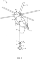
- Figure 1 shows a rotorcraft 1 that illustratively comprises a fuselage 2 with a bottom shell 2c.
- the fuselage 2 forms a cabin 2b for passengers and/or cargo and a tail boom 2a is mounted to the fuselage 2.
- the rotorcraft 1 illustratively further comprises at least one main rotor 1a configured to provide lift and forward or backward thrust during operation, and at least one counter-torque device 3 configured to provide counter-torque during operation, i. e. to counter the torque created by rotation of the at least one main rotor 1a for purposes of balancing the rotorcraft 1 in terms of yaw.
- the at least one counter-torque device 3 is illustratively provided at an aft section of the tail boom 2a, which preferably further comprises a fin 4.
- the at least one counter-torque device 3, as well as the fin 4 provided at the aft section of the tail boom 2a, are merely described for illustrating one possible realization of the rotorcraft 1.
- the rotorcraft 1 is provided with human and/or non-human cargo insertion/extraction means 6.
- the human and/or non-human cargo insertion/extraction means 6 are attached to an associated attachment 5 provided at the bottom shell 2c.
- the attachment 5 is illustratively embodied as an attachment ring which may e. g. be connected to a cable that is coupled to a winch.
- the human and/or non-human cargo insertion/extraction means 6 preferably comprises a rope 7 with a rope interface 7a, such as an eyelet, which is illustratively attached to the attachment 5, e. g. by means of a snap hook respectively carabiner.
- the rope 7 is preferably provided with an attachment interface 8, such as a safety hook or snap hook respectively carabiner 8a.
- the attachment interface 8 is preferably provided to enable a secure and reliable attachment of external components to the rope 7.
- the rope 7 is replaced by a cable.
- an attachment 9 of a human and/or non-human cargo attachment device 10 is attached to the attachment interface 8.
- the attachment 9 is mounted to the human and/or non-human cargo attachment device 10 at an associated mounting interface 11 provided at a carrier device 12 of the human and/or non-human cargo attachment device 10.
- the attachment 9 may be implemented by means of a load hook (9a in Figure 2 ).
- the human and/or non-human cargo attachment device 10 and/or its constituent components are further described below with reference to Figure 2 to Figure 5 .
- the rotorcraft 1 with the human and/or non-human cargo insertion/extraction means 6 is shown in operation.
- the human and/or non-human cargo insertion/extraction means 6 may e. g. be used for inserting/extracting persons, i. e. human cargo, and/or goods and loads, i. e. non-human cargo, into/from a respective environment.
- the rotorcraft 1 is embodied as a helicopter.
- use of the human and/or non-human cargo insertion/extraction means 6 is not limited to use with a helicopter. Instead, the human and/or non-human cargo insertion/extraction means 6 may at least be used with other rotorcrafts, such as e. g. tiltrotor aircrafts, compound helicopters, multicopters and so on.
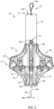
- FIG 2 shows the human and/or non-human cargo attachment device 10 with the attachment 9, the mounting interface 11, and the carrier device 12 of Figure 1 .
- the human and/or non-human cargo attachment device 10 is hereinafter merely referred to as the "cargo attachment device 10".
- the mounting interface 11 is illustratively embodied at a first - in Figure 2 upper - end 12a of the carrier device 12 and provided with the attachment 9 for attachment to a rotorcraft rope or cable via a suitable attachment interface, e. g. the attachment interface 8 provided at the rotorcraft rope 7 of Figure 1 .
- the attachment 9 includes a load hook 9a that is rigidly mounted to the carrier device 12 for attachment to the suitable attachment interface, e. g. the attachment interface 8 provided at the rotorcraft rope 7 of Figure 1 .
- the carrier device 12 is connected to a device body 14.
- the device body 14 may be formed in the shape of an arrowhead, as illustrated.
- Such an arrowhead-shaped form provides for a penetrating design, which is particularly advantageous for use of the cargo attachment device 10 in forested areas, as it enables the device body 14 to penetrate through the trees in the forested areas with minimal resistance.
- the device body 14 is mounted to the carrier device 12 and preferably comprises a stationary body section 15 and a movable body section 16.
- the carrier device 12 is provided at a second - in Figure 2 lower - end 12b with a support end flange 12c and the stationary body section 15 abuts on the support end flange 12c.
- the stationary body section 15 is preferably stationarily arranged on the carrier device 12. In other words, the stationary body section 15 is not movable relative to the carrier device 12, at least not in a direction in which the movable body section 16 is movable, as described by way of example below.
- the stationary body section 15 preferably comprises a sleeve-shaped carrier 15a which is mounted to the carrier device 12 which is preferably sleeve or cylinder-shaped.
- the stationary body section 15 may be rigidly attached to the carrier device 12 and/or the support end flange 12c by any suitable means, such as suitable fasteners, a press-fit connection and/or a welding connection, and so on.
- the stationary body section 15 may be an integral part of the carrier device 12.
- the stationary body section 15 of the device body 14 comprises a plurality of rotatable attachment hooks 17 for attachment of human or non-human external cargo.
- any attached human or non-human external cargo is locked on the device body 14 in closed state of the plurality of rotatable attachment hooks 17 and releasable from the device body 14 in opened state of the plurality of rotatable attachment hooks 17.
- the plurality of rotatable attachment hooks 17 is shown in closed state in Figure 2 .
- the stationary body section 15 comprises a plurality of lateral support arms 19.
- the plurality of lateral support arms 19 is provided with a plurality of pivot bearings 18 which rotatably accommodates the plurality of rotatable attachment hooks 17.
- the plurality of lateral support arms 19 is rigidly mounted to, or integrally formed with, the sleeve-shaped carrier 15a of the stationary body section 15 such that the sleeve-shaped carrier 15a and the plurality of lateral support arms 19 form a star-shaped arrangement in radial direction 10b of the device body 14.
- the plurality of rotatable attachment hooks 17 forms a plurality of main lashing points at the plurality of lateral support arms 19, which is preferentially further provided with a plurality of redundant lashing points 22.
- Use of main lashing points and redundant lashing points may be required for attachment of human external cargo at the device body 14.
- opening and closing of the plurality of rotatable attachment hooks 17 is performed by means of the movable body section 16 of the device body 14. More specifically, the movable body section 16 is preferably movably arranged on the carrier device 12 for enabling movements of the movable body section 16 relative to the stationary body section 15 between a locking position, illustrated in Figure 2 , and a release position, illustrated in Figure 3 .
- the plurality of rotatable attachment hooks 17 is preferably rotatable from the closed state to the opened state via movement of the movable body section 16 from the locking position to the release position, and the plurality of rotatable attachment hooks 17 is preferably rotatable from the opened state to the closed state via movement of the movable body section 16 from the release position to the locking position.
- suitable movements of the movable body section 16 are performed in height direction 10a of the device body 14.
- the movable body section 16 preferably includes at least one slidable carrier sleeve 16a which is slidably supported on the carrier device 12 such that the suitable movements are performed by gliding of the at least one slidable carrier sleeve 16a along the carrier device 12 which is preferably sleeve or cylinder-shaped, in the height direction 10a.
- the movable body section 16 is blockable in the locking position on the carrier device 12 via associated blocking and securing means 13.
- the associated blocking and securing means 13 comprise at least one lock pin 13a.
- the movable body section 16 comprises a plurality of lateral blocking arms 20.
- the plurality of lateral blocking arms 20 is preferably provided for blocking of the plurality of rotatable attachment hooks 17 in the closed state.
- the plurality of lateral blocking arms 20 forms a star-shaped arrangement with the slidable carrier sleeve 16a of the movable body section 16 in the radial direction 10b of the device body 14.
- the plurality of lateral blocking arms 20 is rigidly mounted to, or integrally formed with, the slidable carrier sleeve 16a of the movable body section 16.
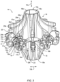
- Figure 3 shows the device body 14 with the stationary body section 15 and the movable body section 16 of Figure 2 , wherein the movable body section 16 is illustrated in the release position.
- the stationary body section 15 comprises the sleeve-shaped carrier 15a and the plurality of lateral support arms 19 with the plurality of pivot bearings 18 which rotatably accommodates the plurality of rotatable attachment hooks 17 forming the main lashing points, as well as with the plurality of redundant lashing points 22.
- the movable body section 16 comprises the slidable carrier sleeve 16a and the plurality of lateral blocking arms 20.
- the slidable carrier sleeve 16a is embodied by a first slidable carrier sleeve section 16b and a second slidable carrier sleeve section 16c.
- the first slidable carrier sleeve section 16b and the second slidable carrier sleeve section 16c are slidable on the carrier device 12 independent of each other.
- the first slidable carrier sleeve section 16b may be connected to a first predetermined number of lateral blocking arms of the plurality of lateral blocking arms 20 of the movable body section 16, and the second slidable carrier sleeve section 16c may be connected to a second predetermined number of lateral blocking arms of the plurality of lateral blocking arms 20.
- the first and second slidable carrier sleeves 16b, 16c are formed as slidable carrier sleeve halves.
- one half of the lateral blocking arms of the plurality of lateral blocking arms 20 is connected to one of the slidable carrier sleeve halves 16b, 16c, while the other half of the lateral blocking arms of the plurality of lateral blocking arms 20 is connected to the other one of the slidable carrier sleeve halves 16c, 16b.
- only a single lateral blocking arm of the plurality of lateral blocking arms 20 is separately labelled with the reference sign 20a.
- a single lateral support arm of the plurality of lateral support arms 19 is separately labelled with the reference sign 19a
- only a single pivot bearing of the plurality of pivot bearings 18 is separately labelled with the reference sign 18a
- only a single rotatable attachment hook of the plurality of rotatable attachment hooks 17 is separately labelled with the reference sign 17a.
- the single rotatable attachment hook 17a, the single pivot bearing 18a, the single lateral support arm 19a, and the single lateral blocking arm 20a are described in more detail hereinafter representative for the plurality of rotatable attachment hooks 17, the plurality of pivot bearings 18, the plurality of lateral support arms 19, and the plurality of lateral blocking arms 20, for simplicity and clarity of the description.
- the lateral support arm 19a preferably comprises an upper mechanical stop 19b and a receiving groove 19c.
- the lateral support arm 19a illustratively comprises a fork-shaped accommodation 19d to which the pivot bearing 18a is mounted.
- the pivot bearing 18a is embodied by means of a bearing pin 18b which is rigidly attached in the fork-shaped accommodation 19d.
- the fork-shaped accommodation 19d illustratively accommodates the rotatable attachment hook 17a rotatably.
- the rotatable attachment hook 17a may be mounted rotatably on the bearing pin 18b.
- the bearing pin 18b may be rotatable in the fork-shaped accommodation 19d and the rotatable attachment hook 17a may be mounted rigidly to the bearing pin 18b.
- the rotatable attachment hook 17a comprises a lock hole 17b provided on a blockable surface 17c. Furthermore, the rotatable attachment hook 17a is preferably embodied with an inner extension 17d, which may be provided with an actuatable extension 17e.
- the actuatable extension 17e is illustratively fork-shaped.
- the inner extension 17d may further be provided with a blockable surface 17f.
- at least one of the blockable surfaces 17c, 17f is blockable by means of the movable body section 16 to prevent rotation of the rotatable attachment hook 17a.
- the rotatable attachment hook 17a is blockable in closed state, illustrated in Figure 2 , by means of the lateral blocking arm 20a.
- the lateral blocking arm 20a is embodied with an outer blocking surface 20c and preferably embodied with an inner blocking surface 20d.
- the outer blocking surface 20c is adapted for blocking of the blockable surface 17c of the rotatable attachment hook 17a
- the inner blocking surface 20d may be adapted for blocking of the blockable surface 17f of the rotatable attachment hook 17a.
- the outer blocking surface 20c of the lateral blocking arm 20a is embodied with a lock pin 20b.
- the lock pin 20b may be provided to form a form-fit connection with the lock hole 17b of the rotatable attachment hook 17a in the closed state of the rotatable attachment hook 17a.
- the lateral blocking arm 20a preferably further comprises an actuating pin 20f that is adapted to cause rotation of the rotatable attachment hook 17a from the closed state to the opened state via movement of the movable body section 16 from the locking position, illustrated in Figure 2 , to the release position, illustrated in Figure 3 .
- the actuating pin 20f is arranged on at least one and, by way of example, on both sides of a lower extension 20e provided on the movable body section 16 such that the actuating pin 20f is located - in Figure 3 - below the actuatable fork 17e of the rotatable attachment hook 17a.
- the actuatable fork 17e is actuatable by means of the movable body section 16, i. e. the actuating pin 20f, for rotation of the rotatable attachment hook 17a from the closed state to the opened state.
- the lateral blocking arm 20g may comprise a mechanical stop 20g.
- the mechanical stop 20g may be provided to abut against the stationary body section 15 in the closed state of the rotatable attachment hook 17a.
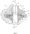
- FIG 4 shows the device body 14 with the stationary body section 15 and the movable body section 16 of Figure 2 and Figure 3 , wherein the movable body section 16 is illustrated in the release position.
- the stationary body section 15 comprises the sleeve-shaped carrier 15a and the plurality of lateral support arms 19 with the plurality of pivot bearings 18 which rotatably accommodates the plurality of rotatable attachment hooks 17 forming the main lashing points, as well as with the plurality of redundant lashing points 22. More specifically, the stationary body section 15 comprises the rotatable attachment hook 17a which is rotatably mounted by means of the pivot bearing 18a to the lateral support arm 19a.
- the movable body section 16 comprises the slidable carrier sleeve 16a with the slidable carrier sleeve halves 16b, 16c, and the plurality of lateral blocking arms 20. More specifically, the movable body section 16 comprises the lateral blocking arm 20a.
- an additional lateral blocking arm of the plurality of lateral blocking arms 20 is separately labelled with the reference sign 21a
- an additional lateral support arm of the plurality of lateral support arms 19 is separately labelled with the reference sign 21c
- an additional rotatable attachment hook of the plurality of rotatable attachment hooks 17 is separately labelled with the reference sign 21b.
- a single redundant lashing point of the plurality of redundant lashing points 22 is individually, illustratively and representatively labelled with the reference sign 22a.
- Figure 4 further details an illustrative realization of the lateral blocking arm 20a with the outer blocking surface 20c that comprises the lock pin 20b, the inner blocking surface 20d, the lower extension 20e, the actuating pin 20f, and the mechanical stop 20g, as well as of the lateral support arm 19a with the upper mechanical stop 19b, the receiving groove 19c, and the fork-shaped accommodation 19d that rotatably accommodates the rotatable attachment hook 17a.
- Figure 4 also further details an illustrative realization of the rotatable attachment hook 17a with the lock hole 17b on the blockable surface 17c, and the inner extension 17d with the actuatable extension 17e and the blockable surface 17f.
- the inner extension 17d is engaged with the actuating pin 20f such that the rotatable attachment hook 17a is rotated into its opened state via movement of the movable body section 16 away from the stationary body section 15 in the height direction 10a of the device body 14 from the locking position, according to Figure 2 , into the illustrated release position, according to Figure 3 .
- the movable body section 16 is preferably blocked by the stationary body section 15, as described hereinafter, to prevent any further movement of the movable body section 16 away from the stationary body section 15.
- the movable body section 16 comprises an - in Figure 4 lower - inner shoulder 16d and the stationary body section 15 comprises an - in Figure 4 upper - outer collar 15b.
- the lower inner shoulder 16d preferably abuts against the upper outer collar 15b in the release position such that any further movement of the movable body section 16 in the height direction 10a away from the stationary body section 15 is prevented.
- the movable body section 16 further comprises an end stop 16e.
- the end stop 16e abuts against the upper outer collar 15b in the locking position such that any further movement of the movable body section 16 in the height direction 10a toward the stationary body section 15 is prevented.
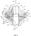
- FIG 5 shows the device body 14 with the stationary body section 15 and the movable body section 16 of Figure 2 to Figure 4 , wherein the movable body section 16 is partly illustrated in the locking position, and partly in an intermediate position.
- the stationary body section 15 comprises the sleeve-shaped carrier 15a and the plurality of lateral support arms 19 with the plurality of pivot bearings 18 which rotatably accommodates the plurality of rotatable attachment hooks 17 forming the main lashing points, as well as with the plurality of redundant lashing points 22. More specifically, the stationary body section 15 comprises the rotatable attachment hook 17a which is rotatably mounted by means of the pivot bearing 18a to the lateral support arm 19a.
- the movable body section 16 comprises the slidable carrier sleeve 16a with the slidable carrier sleeve halves 16b, 16c, and the plurality of lateral blocking arms 20. More specifically, the movable body section 16 comprises the lateral blocking arm 20a.
- Figure 5 further illustrates the lateral blocking arm 20a with the outer blocking surface 20c that comprises the lock pin 20b, the inner blocking surface 20d, the lower extension 20e, the actuating pin 20f, and the mechanical stop 20g, as well as the lateral support arm 19a with the upper mechanical stop 19b, the receiving groove 19c, and the fork-shaped accommodation 19d that rotatably accommodates the rotatable attachment hook 17a.
- Figure 5 also further illustrates the rotatable attachment hook 17a with the lock hole 17b on the blockable surface 17c, the inner extension 17d with the actuatable extension 17e and the blockable surface 17f.
- Figure 5 illustrates the lateral blocking arm 21a, the lateral support arm 21c, and the rotatable attachment hook 21b of Figure 4 .
- the rotatable attachment hook 21b is shown in the intermediate position, wherein the rotatable attachment hook 21b is already rotated into the closed state, but not locked, as illustrated with respect to the rotatable attachment hook 17a.
- the form-fit connection between the lock pin 20b and the lock hole 17b must be released to enable a rotation of the rotatable attachment hook 17a.
- the actuating pin 20f engages with the inner extension 17d. This is illustrated by way of example representatively with the intermediate position of the rotatable attachment hook 21a.
Landscapes
- Engineering & Computer Science (AREA)
- Aviation & Aerospace Engineering (AREA)
- Mechanical Engineering (AREA)
- Load-Engaging Elements For Cranes (AREA)
- Fittings On The Vehicle Exterior For Carrying Loads, And Devices For Holding Or Mounting Articles (AREA)
- Hooks, Suction Cups, And Attachment By Adhesive Means (AREA)
Claims (15)
- Vorrichtung (10) zur Befestigung von menschlicher und/oder nicht-menschlicher Fracht zur Verwendung mit einem Drehflügler (1), umfassend eine Montageschnittstelle (11) mit einer Trägervorrichtung (12) und einer Befestigung (9), die starr an der Trägervorrichtung (12) zur Befestigung an einem Seil oder Kabel (7) eines Drehflüglers angebracht ist; und einen Vorrichtungskörper (14), der an der Trägervorrichtung (12) angebracht ist und einen stationären Körperabschnitt (15) und einen beweglichen Körperabschnitt (16) umfasst, wobei der stationäre Körperabschnitt (15) stationär an der Trägervorrichtung (12) angeordnet ist und eine Mehrzahl von drehbaren Befestigungshaken (17) zur Befestigung von menschlicher oder nicht-menschlicher externer Fracht umfasst, und wobei die angebrachte menschliche oder nicht-menschliche externe Fracht konfiguriert ist, um im geschlossenen Zustand der Mehrzahl von drehbaren Befestigungshaken (17) am Gerätekörper (14) verriegelt zu sein, und konfiguriert ist, um im geöffneten Zustand der Mehrzahl von drehbaren Befestigungshaken (17) vom Vorrichtungskörper (14) lösbar zu sein, und wobei der bewegliche Körperabschnitt (16) beweglich an der Trägervorrichtung (12) angeordnet ist, um Bewegungen des beweglichen Körperabschnitts (16) relativ zu dem stationären Körperabschnitt (15) zwischen einer Verriegelungsposition und einer Freigabeposition zu ermöglichen, wobei jeder der Mehrzahl von drehbaren Befestigungshaken (17) ein drehbarer Befestigungshaken ist, der drehbar an dem stationären Körperabschnitt (15) aufgenommen ist und durch Bewegung des beweglichen Körperabschnitts (16) von der Verriegelungsposition in die Freigabeposition von dem geschlossenen Zustand in den geöffneten Zustand drehbar ist, und wobei die Mehrzahl von drehbaren Befestigungshaken (17) durch Bewegung des beweglichen Körperabschnitts (16) von der Freigabeposition in die Verriegelungsposition von dem geöffneten Zustand in den geschlossenen Zustand drehbar ist; dadurch gekennzeichnet, dass jeder drehbare Befestigungshaken (17a) eine blockierbare Oberfläche (17c) aufweist, dass der bewegliche Körperabschnitt (16) eine Mehrzahl von seitlichen Blockierarmen (20) umfasst und dass jeder seitliche Blockierarm (20a) der Mehrzahl von seitlichen Blockierarmen (20) eine äußere Blockieroberfläche (20c) umfasst, wobei jede blockierbare Oberfläche (17c) im geschlossenen Zustand an einer entsprechenden äußeren Blockieroberfläche (20c) blockiert ist und jede blockierbare Oberfläche (17c) im geöffneten Zustand vom beweglichen Körperabschnitt (16) entfernt ist.
- Vorrichtung (10) zur Befestigung von menschlicher und/oder nicht-menschlicher Fracht nach Anspruch 1, bei der der stationäre Körperabschnitt (15) eine Mehrzahl von seitlichen Stützarmen (19) umfasst und jeder drehbare Befestigungshaken (17a) der Mehrzahl von drehbaren Befestigungshaken (17) drehbar an einem zugeordneten seitlichen Stützarm (19a) der Mehrzahl von seitlichen Stützarmen (19) gelagert ist.
- Vorrichtung (10) zur Befestigung von menschlicher und/oder nicht-menschlicher Fracht nach Anspruch 2, bei der der stationäre Körperabschnitt (15) einen hülsenförmigen Träger (15a) umfasst, der an der Trägervorrichtung (12) angebracht ist, und wobei der hülsenförmige Träger (15a) und die seitlichen Stützarme (19a) der Mehrzahl von seitlichen Stützarmen (19) eine in radialer Richtung (10b) des Vorrichtungskörpers (14) sternförmige Anordnung bilden.
- Vorrichtung (10) zur Befestigung von menschlicher und/oder nicht-menschlicher Fracht nach Anspruch 2 oder 3, bei der jeder seitliche Stützarm (19a) der Mehrzahl von seitlichen Stützarmen (19) eine gabelförmige Aufnahme (19d) umfasst, an der ein zugeordnetes Drehlager (18a) einer Mehrzahl von Drehlagern (18) angebracht ist, wobei jede gabelförmige Aufnahme (19d) einen zugeordneten drehbaren Befestigungshaken (17a) der Mehrzahl von drehbaren Befestigungshaken (17) drehbar aufnimmt.
- Vorrichtung zur Befestigung von menschlicher und/oder nicht-menschlicher Fracht (10) nach einem der vorhergehenden Ansprüche, bei der jeder drehbare Befestigungshaken (17a) der Mehrzahl von drehbaren Befestigungshaken (17) einen Hauptzurrpunkt bildet, und bei der jeder seitliche Stützarm (19a) der Mehrzahl von seitlichen Stützarmen (19) einen redundanten Zurrpunkt (22a) aus einer Mehrzahl von redundanten Zurrpunkten (22) umfasst.
- Vorrichtung (10) zur Befestigung von menschlicher und/oder nicht-menschlicher Fracht nach einem der vorhergehenden Ansprüche, bei der jeder drehbare Befestigungshaken (17a) aus der Mehrzahl von drehbaren Befestigungshaken (17) eine betätigbare Verlängerung (17e) umfasst, die zum Drehen des drehbaren Befestigungshakens (17a) aus dem geschlossenen Zustand in den geöffneten Zustand mittels des beweglichen Körperabschnitts (16) betätigbar ist.
- Vorrichtung zur Befestigung von menschlicher und/oder nicht-menschlicher Fracht (10) nach einem der vorhergehenden Ansprüche, bei der jeder drehbare Befestigungshaken (17a) der Mehrzahl von drehbaren Befestigungshaken (17) mindestens eine blockierbare Fläche (17c, 17f) umfasst, die mittels des beweglichen Körperabschnitts (16) blockierbar ist, um eine Drehung des drehbaren Befestigungshakens (17a) zu verhindern.
- Vorrichtung zur Befestigung von menschlicher und/oder nicht-menschlicher Fracht (10) nach einem der vorhergehenden Ansprüche, bei der der bewegliche Körperabschnitt (16) eine Mehrzahl von seitlichen Blockierarmen (20) umfasst, und bei der jeder seitliche Blockierarm (20a) aus der Mehrzahl von seitlichen Blockierarmen (20) zum Blockieren eines zugeordneten drehbaren Befestigungshakens (17a) aus der Mehrzahl von drehbaren Befestigungshaken (17) im geschlossenen Zustand vorgesehen ist, und bei der der bewegliche Körperabschnitt (16) mindestens eine verschiebbare Trägerhülse (16a) umfasst, die verschiebbar auf der Trägervorrichtung (12) gelagert ist, und wobei die verschiebbare Trägerhülse (16a) und die seitlichen Blockierarme (20a) der Mehrzahl von seitlichen Blockierarmen (20) eine in radialer Richtung (10b) des Vorrichtungskörpers (14) sternförmige Anordnung bilden.
- Vorrichtung (10) zur Befestigung von menschlicher und/oder nicht-menschlicher Fracht nach Anspruch 8, bei der die mindestens eine verschiebbare Trägerhülse (16a) mindestens einen ersten verschiebbaren Trägerhülsenabschnitt (16b) und einen zweiten verschiebbaren Trägerhülsenabschnitt (16c) umfasst, wobei eine erste vorgegebene Anzahl der seitlichen Blockierarme (20a) aus der Mehrzahl von seitlichen Blockierarmen (20) mit dem ersten verschiebbaren Trägerhülsenabschnitt (16b) verbunden ist, wobei eine zweite vorgegebene Anzahl der seitlichen Blockierarme der Mehrzahl von seitlichen Blockierarmen (20) mit dem zweiten verschiebbaren Trägerhülsenabschnitt (16c) verbunden ist, und bei der die ersten und zweiten Trägerhülsenabschnitte (16b, 16c) unabhängig voneinander auf der Trägervorrichtung (12) verschiebbar sind.
- Vorrichtung (10) zur Befestigung von menschlicher und/oder nicht-menschlicher Fracht nach einem der Ansprüche 8 bis 9, bei der jeder seitliche Blockierarm (20a) aus der Mehrzahl von seitlichen Blockierarmen (20) einen Verriegelungsstift (20b) umfasst, der eingerichtet ist, um im geschlossenen Zustand eine formschlüssige Verbindung mit einem zugeordneten Verriegelungsloch (17b) einzugehen, das an dem zugeordneten drehbaren Befestigungshaken (17a) aus der Mehrzahl von drehbaren Befestigungshaken (17) vorgesehen ist.
- Vorrichtung (10) zur Befestigung von menschlicher und/oder nicht-menschlicher Fracht nach einem der Ansprüche 8 bis 10, bei der jeder seitliche Blockierarm (20a) aus der Mehrzahl von seitlichen Blockierarmen (20) einen Betätigungsstift (20f) umfasst, der eingerichtet ist, um durch Bewegen des beweglichen Körperabschnitts (16) von der Verriegelungsposition in die Freigabeposition eine Drehung des zugeordneten drehbaren Befestigungshakens (17a) der Mehrzahl von drehbaren Befestigungshaken (17) aus dem geschlossenen Zustand in den geöffneten Zustand zu bewirken.
- Vorrichtung (10) zur Befestigung von menschlicher und/oder nicht-menschlicher Fracht nach einem der vorhergehenden Ansprüche, bei der der bewegliche Körperabschnitt (16) in der Verriegelungsposition an der Trägervorrichtung (12) über zugeordnete Blockier- und Sicherungsmittel (13) blockierbar ist.
- Vorrichtung (10) zur Befestigung von menschlicher und/oder nicht-menschlicher Fracht nach einem der vorhergehenden Ansprüche, bei der die Trägervorrichtung (12) einen Stütz-Endflansch (12c) umfasst und bei der der stationäre Körperabschnitt (15) an dem Stütz-Endflansch (12c) anliegt.
- Vorrichtung (10) zur Befestigung von menschlicher und/oder nicht-menschlicher Fracht nach einem der vorhergehenden Ansprüche, bei der der Vorrichtungskörper (14) eine pfeilspitzenförmige Gestalt aufweist.
- Vorrichtung (10) zur Befestigung von menschlicher und/oder nicht-menschlicher Fracht nach einem der vorhergehenden Ansprüche, bei der jede äußere Blockieroberfläche (20c) einen Verriegelungsstift (20b) umfasst, der seitliche Blockierarm (20a) ferner eine innere Blockieroberfläche (20d), eine untere Verlängerung (20e), einen Betätigungsstift (20f) und einen mechanischen Anschlag (20g) umfasst, und ein seitlicher Stützarm (19a) einer Mehrzahl von seitlichen Stützarmen (19) einen oberen mechanischen Anschlag (19b), eine Aufnahmenut (19c) und eine gabelförmige Aufnahme (19d) aufweist, die den entsprechenden drehbaren Befestigungshaken (17a) drehbar aufnimmt; und wobei jeder drehbare Befestigungshaken (17a) ein Verriegelungsloch (17b) auf einer entsprechenden blockierbaren Fläche (17c) und eine innere Verlängerung (17d) mit einer betätigbaren Verlängerung (17e) und einer blockierbaren Fläche (17f) aufweist.
Priority Applications (3)
| Application Number | Priority Date | Filing Date | Title |
|---|---|---|---|
| EP21400024.2A EP4197909B1 (de) | 2021-12-15 | 2021-12-15 | Vorrichtung zur befestigung von menschlicher und/oder nicht-menschlicher fracht zur verwendung mit einem drehflügler |
| JP2022171338A JP7485742B2 (ja) | 2021-12-15 | 2022-10-26 | 回転翼航空機で使用するための人及び/又は人以外の貨物取り付けデバイス |
| US17/987,943 US12269712B2 (en) | 2021-12-15 | 2022-11-16 | Human and/or non-human cargo attachment device for use with a rotorcraft |
Applications Claiming Priority (1)
| Application Number | Priority Date | Filing Date | Title |
|---|---|---|---|
| EP21400024.2A EP4197909B1 (de) | 2021-12-15 | 2021-12-15 | Vorrichtung zur befestigung von menschlicher und/oder nicht-menschlicher fracht zur verwendung mit einem drehflügler |
Publications (2)
| Publication Number | Publication Date |
|---|---|
| EP4197909A1 EP4197909A1 (de) | 2023-06-21 |
| EP4197909B1 true EP4197909B1 (de) | 2025-04-23 |
Family
ID=80682622
Family Applications (1)
| Application Number | Title | Priority Date | Filing Date |
|---|---|---|---|
| EP21400024.2A Active EP4197909B1 (de) | 2021-12-15 | 2021-12-15 | Vorrichtung zur befestigung von menschlicher und/oder nicht-menschlicher fracht zur verwendung mit einem drehflügler |
Country Status (3)
| Country | Link |
|---|---|
| US (1) | US12269712B2 (de) |
| EP (1) | EP4197909B1 (de) |
| JP (1) | JP7485742B2 (de) |
Families Citing this family (1)
| Publication number | Priority date | Publication date | Assignee | Title |
|---|---|---|---|---|
| EP4183682B1 (de) * | 2021-11-23 | 2024-01-10 | AIRBUS HELICOPTERS DEUTSCHLAND GmbH | Vorrichtung zur befestigung von menschlicher und/oder nicht-menschlicher fracht zur verwendung mit einem drehflügler |
Family Cites Families (23)
| Publication number | Priority date | Publication date | Assignee | Title |
|---|---|---|---|---|
| US3476A (en) | 1844-03-13 | Ralph bulkley | ||
| US339A (en) | 1837-07-31 | Mode of constructing the wheels of locomotives for asceniding inclined | ||
| US1408940A (en) | 1921-05-02 | 1922-03-07 | Walter C Harley | Adjustable rope fastener |
| US3444569A (en) | 1967-06-21 | 1969-05-20 | Kaman Corp | Air-sea rescue device with flotation collar |
| US3467346A (en) | 1967-11-16 | 1969-09-16 | Kaman Corp | Air-ground rescue device including protective shield assembly therefor |
| US3476339A (en) | 1968-02-21 | 1969-11-04 | Billy Gene Pugh | Jungle recovery device |
| US5593113A (en) * | 1995-02-06 | 1997-01-14 | Cox; Donald P. | Methods and apparatus for selectively attaching and releasing multiple payloads suspended from an aircraft |
| GB2340101B (en) | 1998-07-29 | 2002-02-13 | Allan Brocklebank | Helicopter rescue system |
| FR2782060B1 (fr) | 1998-08-06 | 2000-10-13 | Jean Francois Tardy | Dispositif suspendu a un engin porteur pour la recuperation d'individus ou de materiels |
| US6336260B1 (en) | 2000-07-06 | 2002-01-08 | Basecamp Innovations, Ltd. | Gated rigging plate |
| FR2857269B1 (fr) | 2003-07-09 | 2005-09-16 | Jean Francois Tardy | Nacelle a verrouillage de bras deployables. |
| US20050250396A1 (en) | 2004-05-06 | 2005-11-10 | Hayles David H | Rescue lift |
| GB2466307A (en) | 2008-12-22 | 2010-06-23 | Amsafe Bridport Ltd | A net comprising a net body and a plurality of lifting loops formed from at least two materials |
| JP6165435B2 (ja) * | 2012-12-14 | 2017-07-19 | 朝日航洋株式会社 | フック装置 |
| US9758353B2 (en) * | 2013-12-04 | 2017-09-12 | Innovative Minds, LLC | Wireless controllable carousel independently releasable grapling hooks |
| TR201811744T4 (tr) | 2014-12-23 | 2018-09-21 | Iveco Magirus | Bir kurtarma aparatını kaldırmaya yönelik lanyard tertibatı. |
| EP3109159B1 (de) * | 2015-06-22 | 2019-08-07 | AIRBUS HELICOPTERS DEUTSCHLAND GmbH | Seilaufhängungsvorrichtung mit mindestens einem seilaufhängungsmodul |
| CN205114816U (zh) | 2015-09-30 | 2016-03-30 | 无锡市爱德森机械有限公司 | 一种污水泵复合提升索具 |
| CN108673550A (zh) * | 2016-03-21 | 2018-10-19 | 珠海市磐石电子科技有限公司 | 一种机械手装置 |
| US10398939B1 (en) | 2018-02-09 | 2019-09-03 | Mallory Safety & Supply, Llc | Load sharing snap-linkable safety rigging plate |
| US10974934B2 (en) | 2018-04-20 | 2021-04-13 | Wing Aviation Llc | Perforated capsule hook for stable high speed retract |
| CN112047228B (zh) | 2020-08-05 | 2025-03-07 | 山东鲁普科技有限公司 | 多眼环编织绳索 |
| US11530116B2 (en) | 2020-11-03 | 2022-12-20 | Nelson O. McKay | Seesaw hook apparatus |
-
2021
- 2021-12-15 EP EP21400024.2A patent/EP4197909B1/de active Active
-
2022
- 2022-10-26 JP JP2022171338A patent/JP7485742B2/ja active Active
- 2022-11-16 US US17/987,943 patent/US12269712B2/en active Active
Also Published As
| Publication number | Publication date |
|---|---|
| JP7485742B2 (ja) | 2024-05-16 |
| US12269712B2 (en) | 2025-04-08 |
| EP4197909A1 (de) | 2023-06-21 |
| JP2023088845A (ja) | 2023-06-27 |
| US20230183044A1 (en) | 2023-06-15 |
Similar Documents
| Publication | Publication Date | Title |
|---|---|---|
| US10023313B2 (en) | Rope suspension device with at least one rope suspension module | |
| US7946530B1 (en) | Modular adaptive configured helicopter | |
| AU2015240411B2 (en) | Aerial deployable rescue package | |
| US7699268B2 (en) | Sling release mechanism | |
| PT2046644E (pt) | Sistema de descolagem e aterragem de um veículo aéreo não tripulado | |
| KR100632477B1 (ko) | 캐리어에 현수식으로 구성된 인명구조용 또는 장비회수용장치 | |
| EP4197909B1 (de) | Vorrichtung zur befestigung von menschlicher und/oder nicht-menschlicher fracht zur verwendung mit einem drehflügler | |
| EP2838793B1 (de) | Fallschirmrettungssystem | |
| US11787531B2 (en) | Modular load carrying apparatus with a carrier star | |
| EP4183682B1 (de) | Vorrichtung zur befestigung von menschlicher und/oder nicht-menschlicher fracht zur verwendung mit einem drehflügler | |
| US12209634B2 (en) | Modular attachment device for insertion into a plurality of strands of a braided rope | |
| US20240208649A1 (en) | Collapsible self-supporting human and/or non-human cargo transport device | |
| EP4101760B1 (de) | Modulare lastentragende vorrichtung mit austauschbaren plattformen | |
| US11465760B2 (en) | Tensioned parachute release mechanism | |
| EP4495003A1 (de) | Externer frachtadapter zur verwendung mit einem drehflügler | |
| Nyamagoudar et al. | A novel concept on Mid Air Recovery of crew module | |
| CZ2012258A3 (cs) | Balistický záchranný systém pro letouny s rotujícím krídlem | |
| BEHR | The development of a parachute system for aerial delivery from high speed cargo aircraft | |
| CZ307171B6 (cs) | Padákový záchranný systém |
Legal Events
| Date | Code | Title | Description |
|---|---|---|---|
| PUAI | Public reference made under article 153(3) epc to a published international application that has entered the european phase |
Free format text: ORIGINAL CODE: 0009012 |
|
| STAA | Information on the status of an ep patent application or granted ep patent |
Free format text: STATUS: THE APPLICATION HAS BEEN PUBLISHED |
|
| STAA | Information on the status of an ep patent application or granted ep patent |
Free format text: STATUS: REQUEST FOR EXAMINATION WAS MADE |
|
| AK | Designated contracting states |
Kind code of ref document: A1 Designated state(s): AL AT BE BG CH CY CZ DE DK EE ES FI FR GB GR HR HU IE IS IT LI LT LU LV MC MK MT NL NO PL PT RO RS SE SI SK SM TR |
|
| 17P | Request for examination filed |
Effective date: 20230602 |
|
| RBV | Designated contracting states (corrected) |
Designated state(s): AL AT BE BG CH CY CZ DE DK EE ES FI FR GB GR HR HU IE IS IT LI LT LU LV MC MK MT NL NO PL PT RO RS SE SI SK SM TR |
|
| STAA | Information on the status of an ep patent application or granted ep patent |
Free format text: STATUS: EXAMINATION IS IN PROGRESS |
|
| 17Q | First examination report despatched |
Effective date: 20240411 |
|
| GRAP | Despatch of communication of intention to grant a patent |
Free format text: ORIGINAL CODE: EPIDOSNIGR1 |
|
| STAA | Information on the status of an ep patent application or granted ep patent |
Free format text: STATUS: GRANT OF PATENT IS INTENDED |
|
| GRAS | Grant fee paid |
Free format text: ORIGINAL CODE: EPIDOSNIGR3 |
|
| GRAA | (expected) grant |
Free format text: ORIGINAL CODE: 0009210 |
|
| STAA | Information on the status of an ep patent application or granted ep patent |
Free format text: STATUS: THE PATENT HAS BEEN GRANTED |
|
| INTG | Intention to grant announced |
Effective date: 20250219 |
|
| AK | Designated contracting states |
Kind code of ref document: B1 Designated state(s): AL AT BE BG CH CY CZ DE DK EE ES FI FR GB GR HR HU IE IS IT LI LT LU LV MC MK MT NL NO PL PT RO RS SE SI SK SM TR |
|
| REG | Reference to a national code |
Ref country code: GB Ref legal event code: FG4D |
|
| REG | Reference to a national code |
Ref country code: CH Ref legal event code: EP |
|
| REG | Reference to a national code |
Ref country code: DE Ref legal event code: R096 Ref document number: 602021029552 Country of ref document: DE |
|
| REG | Reference to a national code |
Ref country code: IE Ref legal event code: FG4D |
|
| REG | Reference to a national code |
Ref country code: NL Ref legal event code: MP Effective date: 20250423 |
|
| PG25 | Lapsed in a contracting state [announced via postgrant information from national office to epo] |
Ref country code: NL Free format text: LAPSE BECAUSE OF FAILURE TO SUBMIT A TRANSLATION OF THE DESCRIPTION OR TO PAY THE FEE WITHIN THE PRESCRIBED TIME-LIMIT Effective date: 20250423 |
|
| REG | Reference to a national code |
Ref country code: AT Ref legal event code: MK05 Ref document number: 1787556 Country of ref document: AT Kind code of ref document: T Effective date: 20250423 |
|
| PG25 | Lapsed in a contracting state [announced via postgrant information from national office to epo] |
Ref country code: FI Free format text: LAPSE BECAUSE OF FAILURE TO SUBMIT A TRANSLATION OF THE DESCRIPTION OR TO PAY THE FEE WITHIN THE PRESCRIBED TIME-LIMIT Effective date: 20250423 Ref country code: PT Free format text: LAPSE BECAUSE OF FAILURE TO SUBMIT A TRANSLATION OF THE DESCRIPTION OR TO PAY THE FEE WITHIN THE PRESCRIBED TIME-LIMIT Effective date: 20250825 Ref country code: ES Free format text: LAPSE BECAUSE OF FAILURE TO SUBMIT A TRANSLATION OF THE DESCRIPTION OR TO PAY THE FEE WITHIN THE PRESCRIBED TIME-LIMIT Effective date: 20250423 |
|
| REG | Reference to a national code |
Ref country code: LT Ref legal event code: MG9D |
|
| PG25 | Lapsed in a contracting state [announced via postgrant information from national office to epo] |
Ref country code: GR Free format text: LAPSE BECAUSE OF FAILURE TO SUBMIT A TRANSLATION OF THE DESCRIPTION OR TO PAY THE FEE WITHIN THE PRESCRIBED TIME-LIMIT Effective date: 20250724 Ref country code: NO Free format text: LAPSE BECAUSE OF FAILURE TO SUBMIT A TRANSLATION OF THE DESCRIPTION OR TO PAY THE FEE WITHIN THE PRESCRIBED TIME-LIMIT Effective date: 20250723 |
|
| PG25 | Lapsed in a contracting state [announced via postgrant information from national office to epo] |
Ref country code: PL Free format text: LAPSE BECAUSE OF FAILURE TO SUBMIT A TRANSLATION OF THE DESCRIPTION OR TO PAY THE FEE WITHIN THE PRESCRIBED TIME-LIMIT Effective date: 20250423 |
|
| PG25 | Lapsed in a contracting state [announced via postgrant information from national office to epo] |
Ref country code: BG Free format text: LAPSE BECAUSE OF FAILURE TO SUBMIT A TRANSLATION OF THE DESCRIPTION OR TO PAY THE FEE WITHIN THE PRESCRIBED TIME-LIMIT Effective date: 20250423 |
|
| PG25 | Lapsed in a contracting state [announced via postgrant information from national office to epo] |
Ref country code: HR Free format text: LAPSE BECAUSE OF FAILURE TO SUBMIT A TRANSLATION OF THE DESCRIPTION OR TO PAY THE FEE WITHIN THE PRESCRIBED TIME-LIMIT Effective date: 20250423 |
|
| PG25 | Lapsed in a contracting state [announced via postgrant information from national office to epo] |
Ref country code: AT Free format text: LAPSE BECAUSE OF FAILURE TO SUBMIT A TRANSLATION OF THE DESCRIPTION OR TO PAY THE FEE WITHIN THE PRESCRIBED TIME-LIMIT Effective date: 20250423 |
|
| PG25 | Lapsed in a contracting state [announced via postgrant information from national office to epo] |
Ref country code: RS Free format text: LAPSE BECAUSE OF FAILURE TO SUBMIT A TRANSLATION OF THE DESCRIPTION OR TO PAY THE FEE WITHIN THE PRESCRIBED TIME-LIMIT Effective date: 20250723 |
|
| PG25 | Lapsed in a contracting state [announced via postgrant information from national office to epo] |
Ref country code: IS Free format text: LAPSE BECAUSE OF FAILURE TO SUBMIT A TRANSLATION OF THE DESCRIPTION OR TO PAY THE FEE WITHIN THE PRESCRIBED TIME-LIMIT Effective date: 20250823 |
|
| PG25 | Lapsed in a contracting state [announced via postgrant information from national office to epo] |
Ref country code: LV Free format text: LAPSE BECAUSE OF FAILURE TO SUBMIT A TRANSLATION OF THE DESCRIPTION OR TO PAY THE FEE WITHIN THE PRESCRIBED TIME-LIMIT Effective date: 20250423 |
|
| PGFP | Annual fee paid to national office [announced via postgrant information from national office to epo] |
Ref country code: DE Payment date: 20251211 Year of fee payment: 5 |
|
| PGFP | Annual fee paid to national office [announced via postgrant information from national office to epo] |
Ref country code: GB Payment date: 20251219 Year of fee payment: 5 |
|
| PG25 | Lapsed in a contracting state [announced via postgrant information from national office to epo] |
Ref country code: DK Free format text: LAPSE BECAUSE OF FAILURE TO SUBMIT A TRANSLATION OF THE DESCRIPTION OR TO PAY THE FEE WITHIN THE PRESCRIBED TIME-LIMIT Effective date: 20250423 Ref country code: SM Free format text: LAPSE BECAUSE OF FAILURE TO SUBMIT A TRANSLATION OF THE DESCRIPTION OR TO PAY THE FEE WITHIN THE PRESCRIBED TIME-LIMIT Effective date: 20250423 |
|
| PGFP | Annual fee paid to national office [announced via postgrant information from national office to epo] |
Ref country code: IT Payment date: 20251223 Year of fee payment: 5 |
|
| PGFP | Annual fee paid to national office [announced via postgrant information from national office to epo] |
Ref country code: FR Payment date: 20251229 Year of fee payment: 5 |
|
| PG25 | Lapsed in a contracting state [announced via postgrant information from national office to epo] |
Ref country code: CZ Free format text: LAPSE BECAUSE OF FAILURE TO SUBMIT A TRANSLATION OF THE DESCRIPTION OR TO PAY THE FEE WITHIN THE PRESCRIBED TIME-LIMIT Effective date: 20250423 |
|
| PG25 | Lapsed in a contracting state [announced via postgrant information from national office to epo] |
Ref country code: EE Free format text: LAPSE BECAUSE OF FAILURE TO SUBMIT A TRANSLATION OF THE DESCRIPTION OR TO PAY THE FEE WITHIN THE PRESCRIBED TIME-LIMIT Effective date: 20250423 |
|
| REG | Reference to a national code |
Ref country code: DE Ref legal event code: R097 Ref document number: 602021029552 Country of ref document: DE |
|
| PG25 | Lapsed in a contracting state [announced via postgrant information from national office to epo] |
Ref country code: SK Free format text: LAPSE BECAUSE OF FAILURE TO SUBMIT A TRANSLATION OF THE DESCRIPTION OR TO PAY THE FEE WITHIN THE PRESCRIBED TIME-LIMIT Effective date: 20250423 |
|
| PLBE | No opposition filed within time limit |
Free format text: ORIGINAL CODE: 0009261 |
|
| STAA | Information on the status of an ep patent application or granted ep patent |
Free format text: STATUS: NO OPPOSITION FILED WITHIN TIME LIMIT |
|
| REG | Reference to a national code |
Ref country code: CH Ref legal event code: L10 Free format text: ST27 STATUS EVENT CODE: U-0-0-L10-L00 (AS PROVIDED BY THE NATIONAL OFFICE) Effective date: 20260304 |
|
| PG25 | Lapsed in a contracting state [announced via postgrant information from national office to epo] |
Ref country code: RO Free format text: LAPSE BECAUSE OF FAILURE TO SUBMIT A TRANSLATION OF THE DESCRIPTION OR TO PAY THE FEE WITHIN THE PRESCRIBED TIME-LIMIT Effective date: 20250423 |