EP4197843A1 - Vehicle console with a screen to display overlapping graphical user interfaces and method for safe interaction with overlapping graphical user interfaces - Google Patents
Vehicle console with a screen to display overlapping graphical user interfaces and method for safe interaction with overlapping graphical user interfaces Download PDFInfo
- Publication number
- EP4197843A1 EP4197843A1 EP22208846.0A EP22208846A EP4197843A1 EP 4197843 A1 EP4197843 A1 EP 4197843A1 EP 22208846 A EP22208846 A EP 22208846A EP 4197843 A1 EP4197843 A1 EP 4197843A1
- Authority
- EP
- European Patent Office
- Prior art keywords
- graphical user
- user interface
- virtual element
- console
- machine function
- Prior art date
- Legal status (The legal status is an assumption and is not a legal conclusion. Google has not performed a legal analysis and makes no representation as to the accuracy of the status listed.)
- Pending
Links
- 238000000034 method Methods 0.000 title claims description 24
- 230000003993 interaction Effects 0.000 title claims description 9
- 230000001960 triggered effect Effects 0.000 claims description 9
- 238000001514 detection method Methods 0.000 claims description 3
- 230000006870 function Effects 0.000 description 97
- 230000002265 prevention Effects 0.000 description 5
- 230000001276 controlling effect Effects 0.000 description 2
- 230000001105 regulatory effect Effects 0.000 description 2
- 239000007921 spray Substances 0.000 description 2
- 208000027418 Wounds and injury Diseases 0.000 description 1
- 238000007792 addition Methods 0.000 description 1
- 238000004378 air conditioning Methods 0.000 description 1
- 238000004891 communication Methods 0.000 description 1
- 230000006378 damage Effects 0.000 description 1
- 238000012217 deletion Methods 0.000 description 1
- 230000037430 deletion Effects 0.000 description 1
- 239000004459 forage Substances 0.000 description 1
- 208000014674 injury Diseases 0.000 description 1
- 230000007246 mechanism Effects 0.000 description 1
- 238000012986 modification Methods 0.000 description 1
- 230000004048 modification Effects 0.000 description 1
- 230000000007 visual effect Effects 0.000 description 1
Images


Classifications
-
- G—PHYSICS
- G06—COMPUTING; CALCULATING OR COUNTING
- G06F—ELECTRIC DIGITAL DATA PROCESSING
- G06F3/00—Input arrangements for transferring data to be processed into a form capable of being handled by the computer; Output arrangements for transferring data from processing unit to output unit, e.g. interface arrangements
- G06F3/01—Input arrangements or combined input and output arrangements for interaction between user and computer
- G06F3/048—Interaction techniques based on graphical user interfaces [GUI]
- G06F3/0487—Interaction techniques based on graphical user interfaces [GUI] using specific features provided by the input device, e.g. functions controlled by the rotation of a mouse with dual sensing arrangements, or of the nature of the input device, e.g. tap gestures based on pressure sensed by a digitiser
- G06F3/0488—Interaction techniques based on graphical user interfaces [GUI] using specific features provided by the input device, e.g. functions controlled by the rotation of a mouse with dual sensing arrangements, or of the nature of the input device, e.g. tap gestures based on pressure sensed by a digitiser using a touch-screen or digitiser, e.g. input of commands through traced gestures
- G06F3/04886—Interaction techniques based on graphical user interfaces [GUI] using specific features provided by the input device, e.g. functions controlled by the rotation of a mouse with dual sensing arrangements, or of the nature of the input device, e.g. tap gestures based on pressure sensed by a digitiser using a touch-screen or digitiser, e.g. input of commands through traced gestures by partitioning the display area of the touch-screen or the surface of the digitising tablet into independently controllable areas, e.g. virtual keyboards or menus
-
- G—PHYSICS
- G06—COMPUTING; CALCULATING OR COUNTING
- G06F—ELECTRIC DIGITAL DATA PROCESSING
- G06F3/00—Input arrangements for transferring data to be processed into a form capable of being handled by the computer; Output arrangements for transferring data from processing unit to output unit, e.g. interface arrangements
- G06F3/01—Input arrangements or combined input and output arrangements for interaction between user and computer
- G06F3/048—Interaction techniques based on graphical user interfaces [GUI]
- G06F3/0484—Interaction techniques based on graphical user interfaces [GUI] for the control of specific functions or operations, e.g. selecting or manipulating an object, an image or a displayed text element, setting a parameter value or selecting a range
-
- B60K35/10—
-
- G—PHYSICS
- G06—COMPUTING; CALCULATING OR COUNTING
- G06F—ELECTRIC DIGITAL DATA PROCESSING
- G06F3/00—Input arrangements for transferring data to be processed into a form capable of being handled by the computer; Output arrangements for transferring data from processing unit to output unit, e.g. interface arrangements
- G06F3/01—Input arrangements or combined input and output arrangements for interaction between user and computer
- G06F3/048—Interaction techniques based on graphical user interfaces [GUI]
- G06F3/0481—Interaction techniques based on graphical user interfaces [GUI] based on specific properties of the displayed interaction object or a metaphor-based environment, e.g. interaction with desktop elements like windows or icons, or assisted by a cursor's changing behaviour or appearance
-
- G—PHYSICS
- G06—COMPUTING; CALCULATING OR COUNTING
- G06F—ELECTRIC DIGITAL DATA PROCESSING
- G06F9/00—Arrangements for program control, e.g. control units
- G06F9/06—Arrangements for program control, e.g. control units using stored programs, i.e. using an internal store of processing equipment to receive or retain programs
- G06F9/44—Arrangements for executing specific programs
- G06F9/451—Execution arrangements for user interfaces
-
- B60K2360/11—
-
- B60K2360/119—
-
- B60K2360/1438—
Definitions
- the present disclosure relates generally to a vehicle console with a screen to display overlapping graphical user interfaces and a method for safe interaction with overlapping graphical user interfaces.
- a vehicle for example an agricultural machine as a tractor, a combine, a harvester, a sprayer, etc.
- the console can comprise a screen, e. g. a touch sensitive screen, to display a graphical user interface for interacting with the user.
- the graphical user interface can comprise several virtual elements representing a function. If the user selects the function, e. g. by tipping his finger on a virtual element, the console recognizes the user interaction and executes the function represented by the virtual element.
- the function can be any vehicle function, e. g. functions to control the vehicle interior, functions to control a navigation system, functions to control an infotainment system, etc., as well as any control function of an implement connected to the vehicle.
- the functions as well as additional content as user information, status indicators, etc. can be grouped in different graphical user interfaces, wherein the corresponding graphical user interface is displayed on the screen when needed.
- an additional graphical user interface can be displayed on the screen to display functions and content related to the vehicle interior, as switching lights on / off, regulating of brightness of the lights, regulating of air conditioning, etc.
- the different graphical user interfaces can be displayed in various arrangements on the screen, e. g. a graphical user interface overlapping another graphical user interface (e. g. in terms of a pop-up window).
- the overlapping graphical user interface is displayed on the screen as long as needed and can be closed by a user interaction or automatically by the console. But when the overlapping graphical user interface is closed an unintended execution of a function of the overlapped graphical user interface can occur if a user interaction to execute a function of the overlapping graphical user interface and the closing of the overlapping graphical user interface occur nearly simultaneously. I.
- the user is about to move his finger to a virtual element of the overlapping graphical user interface representing a function intended to be executed by the user while the overlapping graphical user interface is displayed but the user tips the touch sensitive screen with his finger just after the closing of the overlapping graphical user interface so that a virtual element of the overlapped graphical user interface representing a different function is selected instead of the intended function of the overlapping graphical user interface.
- a console for controlling an agricultural machine comprising a screen.
- the screen is configured to display a first graphical user interface with at least a first virtual element for controlling a machine function and to display a second graphical user interface overlapping at least partially the first virtual element.
- the console is configured to prevent an execution of the machine function assigned to the first virtual element of the first graphical user interface, wherein the execution of the machine function assigned to the first virtual element is prevented after an overlap of the first virtual element by the second graphical user interface was cancelled.
- the agricultural machine can be any vehicle or combination of a vehicle and an implement or tool applicable for operations in an agricultural field as a tractor towing an implement as a plough, a forage harvester, a combine, a sprayer, etc.
- the console can be used as a human machine interface (HMI) to control the machine and to execute functions of the machine.
- the console can comprise several input elements as levers, a joystick, buttons, knobs, etc. which can be manipulated by a user.
- the screen of the console can be used as a visual user interface to display virtual elements representing different machine functions, information and other contents.
- a virtual element can be an icon, a pull down menu or a graphical button for example.
- the virtual elements, the information and the other content can be arranged in different graphical user interfaces (GUI) wherein one graphical user interface can overlap another graphical user interface.
- GUI graphical user interface
- a first graphical user interface can be display in a first window and a second graphical interface can be displayed in a second window.
- a virtual element can be selected by one of the input elements, e. g. by pressing a button or moving a cursor with the joystick to the virtual element and selecting it.
- the screen can be touch sensitive so that a machine function displayed on the screen can be selected by tipping a finger on the corresponding virtual element representing the machine function.
- the console can prevent an execution of the machine function assigned to the first virtual element displayed in the first graphical user interface, for example, by ignoring a selection of the first virtual element.
- the execution of the machine function assigned to the first virtual element can be prevented when the first virtual element is overlapped by the second graphical user interface but latest when the overlap of the first virtual element by the second graphical user interface was cancelled.
- a virtual element of the overlapping second graphical user interface can be selected as long as the second graphical user interface is displayed on the screen. But an unintentional execution of the machine function assigned to the first virtual element being part of the first graphical user interface can be effectively avoided even when the second graphical user interface has been cancelled just before the user was about to select the virtual element of the second graphical user interface.
- the overlap of the first graphical use interface, respectively the first virtual element can be cancelled for example by closing the window displaying the second graphical user interface.
- the closing of the window can be triggered by the user or automatically by the console.
- the execution of the machine function assigned to the first virtual element can be prevented until a detection of an event for enabling the machine function assigned to the first virtual element. I. e., after the console recognized the event for enabling the machine function assigned to the first virtual element a selection of the machine function assigned to the first virtual element is no longer be ignored.
- the event for enabling the machine function can be an elapse of a timer.
- the timer can be parametrized by the user to define a time value to be elapsed before the execution of the machine function is enabled.
- Appropriate time values can be any time values, e. g. a value between 250 milliseconds (ms) and 2 seconds (s).
- the machine function assigned to the first virtual element can be configured to control a tool connected with the agricultural machine.
- the tool can be replaceable and can be an agricultural implement as for example a baler, a sprayer, a weeder, a mower, etc.
- the tool can be any other controllable device of the vehicle such as a hitch of a tractor.
- the console can be configured to assign a second machine function to the first virtual element, and to enable an execution of the second machine function assigned to the first virtual element after an overlap of the first virtual element by the second graphical user interface was cancelled.
- the execution of the first machine function can be prevented whereas a selection of the first virtual element to execute a different function is enabled.
- the execution of the second machine function can be disabled if the event for enabling the first machine function assigned to the first virtual element is recognized by the console to enable the first machine function again.
- the first machine function can be assigned to the first virtual element if a first tool is connected with the agricultural machine and the second machine function can be assigned to the first virtual element if a second tool is connected with the agricultural machine. Both tools can be replaceable and can be an agricultural implement.
- the first virtual element can be selected to control the second tool if the execution of the first machine function is prevented and to control the first tool if the execution of the first machine function is enabled.
- the console can be configured to detect an external event triggered outside of the console wherein the second graphical user interface can be closed when the external event is detected.
- the device or tool can be connected with the console, e. g. via a wireless radio link.
- the device or tool can send a message or a status information to the console to be displayed on the screen of the console as an overlapping second graphical user interface. For example, an incoming call from a calling party can be displayed showing the name and the phone number of the calling party, or a warning message from the tool can be sent to the console and displayed as an overlapping second graphical user interface.
- the device or tool can send a signal as an external event triggered outside of the console to the console to close the second graphical user interface overlapping the first graphical user interface. For example, the calling party hangs up the call. Then, the console determines that the call has been terminated and closes the overlapping second graphical user interface showing the name and the phone number of the calling party.
- a signal sent from the tool to the console can be interpreted as an external event, e. g. a signal indicating that the cause of the warning message has been solved to stop displaying the warning message.
- the external event can be any signal, e. g. a communication signal, sent from a device or tool to the console and received by the console.
- the console can comprise a proximity sensor for a touchless interaction with the screen, wherein the second graphical user interface can be closed when the proximity sensor detects a trigger to close the second graphical user interface.
- the user doesn't need to wait that the second graphical user interface will be closed automatically. Instead, the user can manually close the second graphical user interface overlapping the first graphical user interface.
- the proximity sensor detects the intention to close the second graphical user interface before the user touches the touch sensitive screen if the finger is close enough to the screen. If the user moves his finger closer to the screen he could unintentionally touch the screen just after the closing of the second graphical user interface and select a virtual element of the first graphical user interface. But the execution of the function represented by the virtual element is avoided since the execution is prevented by the console after the closing of the second graphical user interface overlapping the first graphical user interface.
- the screen can be configured to detect a touch on the screen wherein the execution of the machine function assigned to the first virtual element can be enabled if the execution is triggered by a trigger different to a touch on the screen.
- a touch of the touch sensitive screen is interpreted by the console as an unintentional selection of the first virtual element whereas the any other trigger is interpreted as intentional.
- the console can comprise an additional input element to which the machine function of the first virtual element is assigned to wherein the trigger different to a touch on the screen for execution of the machine function can be an operation of the additional input element.
- an execution of the function of the first virtual element is prevented by the console only if the user touches the touch sensitive screen but can still be executed if the user selects or triggers the same function by one of the other input elements of the console as the joystick, the buttons, etc.
- the overlap of the first virtual element by the second graphical user interface can be cancelled by moving the second graphical user interface out of the area of the first virtual element.
- the overlap can be cancelled without closing the second graphical user interface to display both the first and the second graphical user interface simultaneously on the screen.
- the screen can be configured to display a second virtual element of the second graphical user interface overlapping at least partially the first virtual element wherein the execution of the machine function assigned to the first virtual element is prevented if an overlap of the first virtual element by the second virtual element was cancelled by the cancellation of the overlap.
- the effective area of the first graphical user interface overlapped by the second virtual element is smaller accordingly.
- the number of executable machine functions each represented by a separate virtual element in the first graphical user interface can be raised since less machine functions will be affected by the prevention due to the smaller effective area of overlap.
- a method for preventing an unintended execution of a machine function comprising the steps of displaying a first graphical user interface on a screen, detecting an event for displaying a second graphical user interface, determining an overlap of at least a virtual element of the first graphical user interface representing a machine function by the second graphical user interface, securing the at least one virtual element of the first graphical user interface, displaying the second graphical user interface, detecting an event for closing the second graphical user interface, detecting an event for enabling the at least one secured virtual element, and enabling the at least one secured virtual element.
- the method can be a computer implemented method.
- the method can comprise additional steps as closing the second graphical user interface, or less steps.
- the order of the steps can be changed, for example, the securing of the at least one virtual element of the first graphical user interface can be executed after the detecting of the event for closing the second graphical user interface.
- the console can comprise a controller configured to carry out the method mentioned above.
- Fig. 1 shows an agricultural machine 1 in terms of a vehicle with an attached tool in terms of a spray assembly.
- Such kind of agricultural vehicle is disclosed in US patent publication US 2015/0201552 A1, by Petrus H. J. Bouten, published on 23rd of July 2015 , which is incorporated by reference hereby.
- other type of vehicles and / or tools or implements could be used the following disclosure refers to the vehicle mentioned above by way of example.
- the vehicle 1 has a pivot hinge boom assembly 24.
- the pivot hinge boom assembly 24 is attached to a chassis of the vehicle 1.
- the pivot hinge boom assembly 24 includes load carrying arms such as left crane arm 30 and right crane arm 32.
- the pivot hinge boom assembly 24 also includes nozzle carrying arms such as left nozzle arm 34 and right nozzle arm 36.
- the left and right crane arms 30, 32 are pivotally attached to a central support bar 40 at pivot hinges (see pivot hinge 42 in Fig. 1 ).
- Hydraulic cylinders 46 control pivoting movement of crane arms 30, 32 about pivot axes of the corresponding pivot hinges.
- Hydraulic cylinders 46 can be actuated by a user seated in cab 14 of vehicle 1 operating a console 6 or by a programmed or programmable control unit 2.
- the control unit 2 can be part of the console 6.
- a hinge joint 54 of each nozzle arm 34, 36 is attached at an end 56 of each crane arm 30, 32.
- the hinge joint 54 joins two sections 58 of each nozzle arm 34, 36, labeled as inner section 58a and outer section 58b.
- sections 58 can swing about a pivot axis to allow nozzle arms 34, 36 to unfold.
- the inner section 58a of left nozzle arm 34 is opening from the stowed configuration by pivoting about the pivot axis of hinge joint 54.
- Such movement can be selectively controlled by mechanisms including hydraulic and electric actuators, for example.
- Such control can be input by a user seated in cab 14 of vehicle 1 operating the console 6 or by the programmed or programmable control unit 2.
- the control unit 2 comprises a controller 3, a memory 4 and an interface 5.
- the memory 4 contains data and executable programs (computer-implemented procedures or methods) that can be retrieved, processed and executed by the controller 3.
- the controller 3 can also send or receive data or signals via the interface 5 and store the data or signals in the memory 4.
- the controller 3 can receive signals form the console 6 or external events triggered outside of the console 6.
- the controller 3 can also generate control signals to control actuators of the vehicle 1 such as the hydraulic and electric actuators of the spray assembly.
- Fig. 3 shows the console 6 comprising a screen 7, multiple input elements as a joystick 8 and buttons 9 and a proximity sensor 18 to detect a finger 17 or a human hand 16 approaching the screen 7.
- the screen 7 is touch sensitive and recognizes a tipping of the finger 17 on the surface of the screen 7.
- the screen 7 is shown in Fig. 4 and Fig. 5 in more detail.
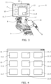
- the screen 7 displays a first graphical user interface 10 comprising several virtual elements 11 as virtual elements 11.1 to 11.9.
- the screen 7 displays the first graphical user interface 10 as shown in Fig. 4 and a second graphical user interface 12 overlapping the first graphical user interface 10.
- the second graphical user interface 12 comprises at least a virtual element 13.
- Each virtual element 11.1 to 11.9 and 13 represents a machine function.
- the machine function can be selected by the user if he tips his finger 17 on the corresponding virtual element 11.1 to 11.9 or 13.
- the selection of the virtual element is recognized by the controller 3.
- the controller 3 initiates or executes the function represented by the virtual element.
- the machine function of the virtual element 11.7 can trigger the corresponding actuator to unfold the left nozzle arm 34 and the machine function of the virtual element 11.9 can trigger the corresponding actuator to unfold the right nozzle arm 36.
- buttons 9. All functions represented by the virtual elements 11.1 to 11.9 and 13 can additionally be assigned to the buttons 9. l.e., the left or the right nozzle arms 34 and 36 can be unfolded by pressing one of the buttons 9. By pressing a different button, the left or the right nozzle arms 34 and 36 can be folded.
- the joystick 8 can be operated by the user to drive the agricultural machine 1, e. g. to accelerate, steer and brake.
- the proximity sensor 18 of the console 6 recognizes when the user moves his hand 16 or his finger 17 towards the screen 7. If the hand 16 or the finger 17 comes close enough to the screen 7 a virtual element 11, 13 can be selected to execute the machine function assigned to it without getting in contact with the screen 7.
- Fig. 8 shows a method for a safe interaction with overlapping graphical user interfaces for preventing an unintended execution of a machine function.
- the method can be stored in the memory 4 of the control unit 2 as a computer implemented method and carried out by the controller 3 of the control unit 2.
- step S100 starts with step S100 and proceeds to step S101 to display the first graphical user interface 10, as shown in Fig. 4 , on the screen 7 of the console 6. All virtual elements 11 of the first graphical user interface 10 are visible for the user and can be selected to execute a machine function assigned to the corresponding virtual element as described above.
- step S102 to detect an event for displaying the second graphical user interface 12, as shown in Fig. 5 , on the screen 7.
- the second graphical user interface 12 can be displayed as a pop-up window if a specific condition is fulfilled.
- the event can be an error detected by the control unit 2, e. g. if the unfolding of the nozzle arms 34, 36 fails, to display a warning message in the second graphical user interface 12.
- the event can be the selection of one of the virtual elements 11 recognized by the controller 3 to display additional functions or virtual elements 13 and contents related to the selected virtual element in terms of a submenu in the second graphical user interface 12.
- the second graphical user interface 12 displayed as submenu can comprise several functions to control the pivot hinge boom assembly 24.
- the event can be an external phone call from a calling party.
- the event can be recognized by the controller 3 to display details of the incoming call as the phone number, the name of the calling party, etc. in the second graphical user interface 12.
- any other event can be detected by the control unit 2, respectively by the controller 3 to display content related to the event in the second graphical user interface 12.
- step S103 determines which virtual elements 11 of the first graphical user interface 10 will be overlapped by the second graphical user interface 12.
- the second user interface 12 overlaps the virtual elements 11.2, 11.3, 11.5, 11.6, 11.8 and 11.9 of the first graphical user interface 10.
- the controller 3 can also determine the area of each virtual element 11 of the first graphical user interface 10 overlapped by the second graphical user interface 12.
- the virtual elements 11.5 and 11.8 are fully overlapped by the second graphical user interface 12 as indicated by the areas 15.1 and 15.3 whereas the virtual elements 11.2, 11.3, 11.6 and 11.9 are covered partly by the second graphical user interface 12 as indicated by the areas 15.2, 15.4, 15.5 and 15.6.
- the controller 3 can also determine which virtual elements 11 of the first graphical user interface 10 will be overlapped by the virtual element 13 of the second graphical user interface 12. As can be seen in Fig. 6 , the virtual element 13 of the second graphical user interface 12 overlaps the virtual elements 11.8 and 11.9 of the first graphical user interface 10. The controller 3 can also determine the area of each virtual element 11 overlapped by the virtual element 13 of the second graphical user interface 12. As can be seen in Fig. 6 , the virtual elements 11.8 and 11.9 are overlapped by the virtual element 13 as indicated by the areas 14.1 and 14.2.
- step S104 to secure the virtual elements 11 being overlapped by the second graphical user interface 12 or by the virtual element 13 of the second graphical user interface 12 against an execution of the corresponding machine function assigned to them.
- the controller 3 prevents an execution of the machine function when the user selects the corresponding virtual element on the screen 7.
- a selection by touching the screen 7 may be recognized by the touch sensitive screen 7 or by the proximity sensor 18 but the controller 3 ignores the selection to avoid the execution of the assigned function.
- the machine functions prevented from execution by selecting the corresponding virtual element are still executable if another input element such as the buttons 9 or the joystick 8 is operated to which the corresponding functions are assigned to.
- step S105 to display the second graphical user interface 12 triggered by the event of step S102 as shown in Fig. 3 or Fig. 5 .
- the second graphical user interface 12 can be a pop-up window.
- step S106 to detect an event for cancelling an overlap of the first graphical user interface 10, respectively the affected virtual elements of the first graphical user interface 10 (as virtual element 11.9 in Fig. 5 ).
- the overlap can be cancelled by closing the second graphical user interface 12.
- the event can be an intention of the user to close the second graphical user interface 12 detected by the proximity sensor 18 when the user moves his finger 17 or his hand 16 close to the screen 7.
- the second graphical user interface 12 can be closed automatically by the control unit 2, for example if a warning message is no longer valid or if the execution of a machine function displayed as a virtual element in the second graphical user interface 12 was finished.
- the second graphical user interface 12 displays contents related to a phone call the second graphical user interface 12 can be closed automatically when the call ends.
- the event for closing the second graphical user interface 12 can be an external event triggered outside of the console 6, e. g. when the calling party hangs up the call.
- other events can be detected which will trigger a closing of the second graphical user interface 12. Due to the event for closing the second graphical user interface 12 the controller 3 closes the second graphical user interface 12.
- the second graphical user interface 12 can be moved out of the area of the virtual elements.
- the second graphical user interface 12 can be arranged next to the first graphical user interface 10 to display both graphical user interfaces 10 and 12 side by side on the screen 7.
- the overlap can be canceled by closing of the second graphical user interface 12 or by moving the overlapping virtual element of the second graphical user interface 12 out of the area of the overlapped virtual elements of the first graphical user interface 10.
- step S104 After cancelling the overlap the virtual elements of the first graphical user interface 10 having been overlapped by the second graphical user interface 12 become completely visible again so that they can be touched by the user on the screen 7. But the prevention to execute a virtual element having been overlapped by the second graphical user interface 12 or by the virtual element 13 of the second graphical user interface 12 as activated in step S104 is still active. If the user selects a corresponding virtual element of the first graphical user interface 10 to execute an assigned function the selection is ignored by the controller 3 to avoid an execution of the assigned function.
- an unintentional execution of a machine function can be prevented at a moment at which the second graphical user interface 12 has been closed automatically just before the user could intentionally touch the second graphical user interface 12 and therefore touches unintentionally the first graphical user interface 10. Since, by way of example, an unintentional execution of the function assigned to the virtual element 11.9 to (un-)fold the right nozzle arm 36 of the agricultural machine 1 could injure a person standing next to the nozzle arm 36 a potential injury can be prevented due to the prevention to execute the function assigned to the corresponding virtual element 11.9 after the overlap of the virtual element 11.9 by the second graphical user interface 12 was cancelled.
- a second machine function can be assigned to a virtual element of the first graphical user interface 10 to be executed instead of the primary (first) machine function if the virtual element was secured due to an overlap.
- the controller 3 can enable the second machine function when an overlap of the secured virtual element was cancelled. I. e., if the user selects (unintentionally) a secured virtual element the primary machine function is ignored but the second machine function is executed by the controller 3.
- the second machine function doesn't pose a threat to anybody.
- the second machine function can display machine information on the screen 7 or a message that the virtual element selected by the user is secured and an execution of the primary machine function of the virtual element is prevented until an event for enabling the secured virtual element will occur.
- the second machine function can be enabled as long as the virtual element is secured and will be disabled when the secured virtual element will be enabled to allow the execution of the primary machine function.
- a first and a second tool can be connected with the agricultural machine 1 wherein the primary machine function and the second machine function are assigned to the virtual element if both tools are connected with the agricultural machine 1.
- the first tool can be controlled by the primary (first) machine function and the second tool can be controlled by the second machine function. Since the controllability of the first and the second function depends on whether the corresponding virtual element is secured or not, the first tool is controllable if the virtual element is unsecured and the second tool is controllable if the virtual element is secured.
- the method proceeds to step S107 to detect an event for enabling (unsecuring) the secured virtual elements and for cancelling the prevention to allow the execution of the machine function assigned to these virtual elements.
- the event for enabling the secured virtual elements can be an elapse of a timer.
- the timer can be started by the controller 3 just after the detection of the event for closing the second graphical user interface 12 at step S106.
- the timer can be some milliseconds up to a few seconds, e. g. 400 ms to 2 s.
- the timer can be adjustable by the user to define a comfortable timer value.
- the event for enabling the secured virtual elements can be any other event such as an event detected by the proximity sensor 18.
- step S108 the method proceeds to step S108 to enable the secured virtual element, e. g. virtual element 11.9, before the method ends with step S109. Then, the prevention is cancelled and the (primary / first) machine function of the virtual element is executable again.
- the secured virtual element e. g. virtual element 11.9
Abstract
Description
- The present disclosure relates generally to a vehicle console with a screen to display overlapping graphical user interfaces and a method for safe interaction with overlapping graphical user interfaces.
- A vehicle, for example an agricultural machine as a tractor, a combine, a harvester, a sprayer, etc., can comprise a console to be operated by a user to control the vehicle. The console can comprise a screen, e. g. a touch sensitive screen, to display a graphical user interface for interacting with the user. The graphical user interface can comprise several virtual elements representing a function. If the user selects the function, e. g. by tipping his finger on a virtual element, the console recognizes the user interaction and executes the function represented by the virtual element. The function can be any vehicle function, e. g. functions to control the vehicle interior, functions to control a navigation system, functions to control an infotainment system, etc., as well as any control function of an implement connected to the vehicle.
- The functions as well as additional content as user information, status indicators, etc., can be grouped in different graphical user interfaces, wherein the corresponding graphical user interface is displayed on the screen when needed. For example, if the function to control the vehicle interior is called an additional graphical user interface can be displayed on the screen to display functions and content related to the vehicle interior, as switching lights on / off, regulating of brightness of the lights, regulating of air conditioning, etc. The different graphical user interfaces can be displayed in various arrangements on the screen, e. g. a graphical user interface overlapping another graphical user interface (e. g. in terms of a pop-up window).
- The overlapping graphical user interface is displayed on the screen as long as needed and can be closed by a user interaction or automatically by the console. But when the overlapping graphical user interface is closed an unintended execution of a function of the overlapped graphical user interface can occur if a user interaction to execute a function of the overlapping graphical user interface and the closing of the overlapping graphical user interface occur nearly simultaneously. I. e., the user is about to move his finger to a virtual element of the overlapping graphical user interface representing a function intended to be executed by the user while the overlapping graphical user interface is displayed but the user tips the touch sensitive screen with his finger just after the closing of the overlapping graphical user interface so that a virtual element of the overlapped graphical user interface representing a different function is selected instead of the intended function of the overlapping graphical user interface.
- It is an objective to provide a console with a screen for displaying overlapping graphical user interfaces configured for a safe user interaction with overlapping graphical user interfaces to avoid the execution of unintended functions, e. g. at the moment when an overlapping graphical user interface is closed.
- According to an aspect of the invention there is provided a console for controlling an agricultural machine comprising a screen. The screen is configured to display a first graphical user interface with at least a first virtual element for controlling a machine function and to display a second graphical user interface overlapping at least partially the first virtual element. The console is configured to prevent an execution of the machine function assigned to the first virtual element of the first graphical user interface, wherein the execution of the machine function assigned to the first virtual element is prevented after an overlap of the first virtual element by the second graphical user interface was cancelled.
- The agricultural machine can be any vehicle or combination of a vehicle and an implement or tool applicable for operations in an agricultural field as a tractor towing an implement as a plough, a forage harvester, a combine, a sprayer, etc. The console can be used as a human machine interface (HMI) to control the machine and to execute functions of the machine. The console can comprise several input elements as levers, a joystick, buttons, knobs, etc. which can be manipulated by a user. The screen of the console can be used as a visual user interface to display virtual elements representing different machine functions, information and other contents. A virtual element can be an icon, a pull down menu or a graphical button for example.
- The virtual elements, the information and the other content can be arranged in different graphical user interfaces (GUI) wherein one graphical user interface can overlap another graphical user interface. For example a first graphical user interface can be display in a first window and a second graphical interface can be displayed in a second window. For execution of a machine function, a virtual element can be selected by one of the input elements, e. g. by pressing a button or moving a cursor with the joystick to the virtual element and selecting it. In addition, the screen can be touch sensitive so that a machine function displayed on the screen can be selected by tipping a finger on the corresponding virtual element representing the machine function.
- The console can prevent an execution of the machine function assigned to the first virtual element displayed in the first graphical user interface, for example, by ignoring a selection of the first virtual element. The execution of the machine function assigned to the first virtual element can be prevented when the first virtual element is overlapped by the second graphical user interface but latest when the overlap of the first virtual element by the second graphical user interface was cancelled. Thus, a virtual element of the overlapping second graphical user interface can be selected as long as the second graphical user interface is displayed on the screen. But an unintentional execution of the machine function assigned to the first virtual element being part of the first graphical user interface can be effectively avoided even when the second graphical user interface has been cancelled just before the user was about to select the virtual element of the second graphical user interface.
- The overlap of the first graphical use interface, respectively the first virtual element can be cancelled for example by closing the window displaying the second graphical user interface. The closing of the window can be triggered by the user or automatically by the console.
- The execution of the machine function assigned to the first virtual element can be prevented until a detection of an event for enabling the machine function assigned to the first virtual element. I. e., after the console recognized the event for enabling the machine function assigned to the first virtual element a selection of the machine function assigned to the first virtual element is no longer be ignored.
- The event for enabling the machine function can be an elapse of a timer. The timer can be parametrized by the user to define a time value to be elapsed before the execution of the machine function is enabled. Appropriate time values can be any time values, e. g. a value between 250 milliseconds (ms) and 2 seconds (s).
- The machine function assigned to the first virtual element can be configured to control a tool connected with the agricultural machine. The tool can be replaceable and can be an agricultural implement as for example a baler, a sprayer, a weeder, a mower, etc. Alternatively, the tool can be any other controllable device of the vehicle such as a hitch of a tractor.
- The console can be configured to assign a second machine function to the first virtual element, and to enable an execution of the second machine function assigned to the first virtual element after an overlap of the first virtual element by the second graphical user interface was cancelled. Thus, the execution of the first machine function can be prevented whereas a selection of the first virtual element to execute a different function is enabled. The execution of the second machine function can be disabled if the event for enabling the first machine function assigned to the first virtual element is recognized by the console to enable the first machine function again.
- The first machine function can be assigned to the first virtual element if a first tool is connected with the agricultural machine and the second machine function can be assigned to the first virtual element if a second tool is connected with the agricultural machine. Both tools can be replaceable and can be an agricultural implement. Thus, the first virtual element can be selected to control the second tool if the execution of the first machine function is prevented and to control the first tool if the execution of the first machine function is enabled.
- The console can be configured to detect an external event triggered outside of the console wherein the second graphical user interface can be closed when the external event is detected.
- The device or tool can be connected with the console, e. g. via a wireless radio link. The device or tool can send a message or a status information to the console to be displayed on the screen of the console as an overlapping second graphical user interface. For example, an incoming call from a calling party can be displayed showing the name and the phone number of the calling party, or a warning message from the tool can be sent to the console and displayed as an overlapping second graphical user interface.
- The device or tool can send a signal as an external event triggered outside of the console to the console to close the second graphical user interface overlapping the first graphical user interface. For example, the calling party hangs up the call. Then, the console determines that the call has been terminated and closes the overlapping second graphical user interface showing the name and the phone number of the calling party. Analogously, a signal sent from the tool to the console can be interpreted as an external event, e. g. a signal indicating that the cause of the warning message has been solved to stop displaying the warning message. So in general, the external event can be any signal, e. g. a communication signal, sent from a device or tool to the console and received by the console.
- The console can comprise a proximity sensor for a touchless interaction with the screen, wherein the second graphical user interface can be closed when the proximity sensor detects a trigger to close the second graphical user interface.
- I. e., the user doesn't need to wait that the second graphical user interface will be closed automatically. Instead, the user can manually close the second graphical user interface overlapping the first graphical user interface. The proximity sensor detects the intention to close the second graphical user interface before the user touches the touch sensitive screen if the finger is close enough to the screen. If the user moves his finger closer to the screen he could unintentionally touch the screen just after the closing of the second graphical user interface and select a virtual element of the first graphical user interface. But the execution of the function represented by the virtual element is avoided since the execution is prevented by the console after the closing of the second graphical user interface overlapping the first graphical user interface.
- The screen can be configured to detect a touch on the screen wherein the execution of the machine function assigned to the first virtual element can be enabled if the execution is triggered by a trigger different to a touch on the screen.
- Thus, a touch of the touch sensitive screen is interpreted by the console as an unintentional selection of the first virtual element whereas the any other trigger is interpreted as intentional.
- The console can comprise an additional input element to which the machine function of the first virtual element is assigned to wherein the trigger different to a touch on the screen for execution of the machine function can be an operation of the additional input element.
- I. e., an execution of the function of the first virtual element is prevented by the console only if the user touches the touch sensitive screen but can still be executed if the user selects or triggers the same function by one of the other input elements of the console as the joystick, the buttons, etc.
- The overlap of the first virtual element by the second graphical user interface can be cancelled by moving the second graphical user interface out of the area of the first virtual element.
- I. e., the overlap can be cancelled without closing the second graphical user interface to display both the first and the second graphical user interface simultaneously on the screen.
- The screen can be configured to display a second virtual element of the second graphical user interface overlapping at least partially the first virtual element wherein the execution of the machine function assigned to the first virtual element is prevented if an overlap of the first virtual element by the second virtual element was cancelled by the cancellation of the overlap.
- Since the area of the second virtual element is typically smaller than the area of the second graphical user interface the effective area of the first graphical user interface overlapped by the second virtual element is smaller accordingly. Thus, the number of executable machine functions each represented by a separate virtual element in the first graphical user interface can be raised since less machine functions will be affected by the prevention due to the smaller effective area of overlap.
- According to an aspect of the invention there is provided a method for preventing an unintended execution of a machine function comprising the steps of displaying a first graphical user interface on a screen, detecting an event for displaying a second graphical user interface, determining an overlap of at least a virtual element of the first graphical user interface representing a machine function by the second graphical user interface, securing the at least one virtual element of the first graphical user interface, displaying the second graphical user interface, detecting an event for closing the second graphical user interface, detecting an event for enabling the at least one secured virtual element, and enabling the at least one secured virtual element.
- The method can be a computer implemented method. The method can comprise additional steps as closing the second graphical user interface, or less steps. The order of the steps can be changed, for example, the securing of the at least one virtual element of the first graphical user interface can be executed after the detecting of the event for closing the second graphical user interface. The console can comprise a controller configured to carry out the method mentioned above.
- Several aspects of the invention will now be described, by way of example only, with reference to the accompanying drawings, in which:
-
Fig. 1 shows an agricultural machine comprising a console; -
Fig. 2 shows a control unit for carrying out a method; -
Fig. 3 shows the console; -
Fig. 4 shows a first graphical user interface; -
Fig. 5 to Fig. 7 show the first graphical user interface overlapped by a second graphical user interface; -
Fig. 1 shows anagricultural machine 1 in terms of a vehicle with an attached tool in terms of a spray assembly. Such kind of agricultural vehicle is disclosed in US patent publicationUS 2015/0201552 A1, by Petrus H. J. Bouten, published on 23rd of July 2015 , which is incorporated by reference hereby. Although other type of vehicles and / or tools or implements could be used the following disclosure refers to the vehicle mentioned above by way of example. - The
vehicle 1 has a pivothinge boom assembly 24. The pivothinge boom assembly 24 is attached to a chassis of thevehicle 1. The pivothinge boom assembly 24 includes load carrying arms such asleft crane arm 30 andright crane arm 32. The pivothinge boom assembly 24 also includes nozzle carrying arms such asleft nozzle arm 34 andright nozzle arm 36. The left andright crane arms central support bar 40 at pivot hinges (seepivot hinge 42 inFig. 1 ).Hydraulic cylinders 46 control pivoting movement ofcrane arms crane arms Hydraulic cylinders 46 can be actuated by a user seated incab 14 ofvehicle 1 operating aconsole 6 or by a programmed orprogrammable control unit 2. Thecontrol unit 2 can be part of theconsole 6. - A
hinge joint 54 of eachnozzle arm end 56 of eachcrane arm nozzle arm inner section 58a andouter section 58b. One or both of sections 58 can swing about a pivot axis to allownozzle arms inner section 58a ofleft nozzle arm 34 is opening from the stowed configuration by pivoting about the pivot axis of hinge joint 54. Such movement can be selectively controlled by mechanisms including hydraulic and electric actuators, for example. Such control can be input by a user seated incab 14 ofvehicle 1 operating theconsole 6 or by the programmed orprogrammable control unit 2. - As shown in
Fig. 2 , thecontrol unit 2 comprises acontroller 3, amemory 4 and aninterface 5. Thememory 4 contains data and executable programs (computer-implemented procedures or methods) that can be retrieved, processed and executed by thecontroller 3. Thecontroller 3 can also send or receive data or signals via theinterface 5 and store the data or signals in thememory 4. For example, thecontroller 3 can receive signals form theconsole 6 or external events triggered outside of theconsole 6. Thecontroller 3 can also generate control signals to control actuators of thevehicle 1 such as the hydraulic and electric actuators of the spray assembly. -
Fig. 3 shows theconsole 6 comprising ascreen 7, multiple input elements as ajoystick 8 andbuttons 9 and aproximity sensor 18 to detect afinger 17 or ahuman hand 16 approaching thescreen 7. Thescreen 7 is touch sensitive and recognizes a tipping of thefinger 17 on the surface of thescreen 7. Thescreen 7 is shown inFig. 4 andFig. 5 in more detail. As depicted inFig. 4 , thescreen 7 displays a firstgraphical user interface 10 comprising severalvirtual elements 11 as virtual elements 11.1 to 11.9. As depicted inFig. 3 andFig. 5 , thescreen 7 displays the firstgraphical user interface 10 as shown inFig. 4 and a secondgraphical user interface 12 overlapping the firstgraphical user interface 10. The secondgraphical user interface 12 comprises at least avirtual element 13. Each virtual element 11.1 to 11.9 and 13 represents a machine function. The machine function can be selected by the user if he tips hisfinger 17 on the corresponding virtual element 11.1 to 11.9 or 13. The selection of the virtual element is recognized by thecontroller 3. Then, thecontroller 3 initiates or executes the function represented by the virtual element. For example, the machine function of the virtual element 11.7 can trigger the corresponding actuator to unfold theleft nozzle arm 34 and the machine function of the virtual element 11.9 can trigger the corresponding actuator to unfold theright nozzle arm 36. - All functions represented by the virtual elements 11.1 to 11.9 and 13 can additionally be assigned to the
buttons 9. l.e., the left or theright nozzle arms buttons 9. By pressing a different button, the left or theright nozzle arms joystick 8 can be operated by the user to drive theagricultural machine 1, e. g. to accelerate, steer and brake. - The
proximity sensor 18 of the console 6 (seeFig. 3 ) recognizes when the user moves hishand 16 or hisfinger 17 towards thescreen 7. If thehand 16 or thefinger 17 comes close enough to the screen 7 avirtual element screen 7. -
Fig. 8 shows a method for a safe interaction with overlapping graphical user interfaces for preventing an unintended execution of a machine function. The method can be stored in thememory 4 of thecontrol unit 2 as a computer implemented method and carried out by thecontroller 3 of thecontrol unit 2. - The method starts with step S100 and proceeds to step S101 to display the first
graphical user interface 10, as shown inFig. 4 , on thescreen 7 of theconsole 6. Allvirtual elements 11 of the firstgraphical user interface 10 are visible for the user and can be selected to execute a machine function assigned to the corresponding virtual element as described above. - The method proceeds to step S102 to detect an event for displaying the second
graphical user interface 12, as shown inFig. 5 , on thescreen 7. l. e., the secondgraphical user interface 12 can be displayed as a pop-up window if a specific condition is fulfilled. For example, the event can be an error detected by thecontrol unit 2, e. g. if the unfolding of thenozzle arms graphical user interface 12. The event can be the selection of one of thevirtual elements 11 recognized by thecontroller 3 to display additional functions orvirtual elements 13 and contents related to the selected virtual element in terms of a submenu in the secondgraphical user interface 12. For example, the secondgraphical user interface 12 displayed as submenu can comprise several functions to control the pivothinge boom assembly 24. The event can be an external phone call from a calling party. The event can be recognized by thecontroller 3 to display details of the incoming call as the phone number, the name of the calling party, etc. in the secondgraphical user interface 12. Alternatively, any other event can be detected by thecontrol unit 2, respectively by thecontroller 3 to display content related to the event in the secondgraphical user interface 12. - The method proceeds to step S103 to determine which
virtual elements 11 of the firstgraphical user interface 10 will be overlapped by the secondgraphical user interface 12. As can be seen inFig. 7 , thesecond user interface 12 overlaps the virtual elements 11.2, 11.3, 11.5, 11.6, 11.8 and 11.9 of the firstgraphical user interface 10. Thecontroller 3 can also determine the area of eachvirtual element 11 of the firstgraphical user interface 10 overlapped by the secondgraphical user interface 12. As can be seenFig. 7 , the virtual elements 11.5 and 11.8 are fully overlapped by the secondgraphical user interface 12 as indicated by the areas 15.1 and 15.3 whereas the virtual elements 11.2, 11.3, 11.6 and 11.9 are covered partly by the secondgraphical user interface 12 as indicated by the areas 15.2, 15.4, 15.5 and 15.6. - The
controller 3 can also determine whichvirtual elements 11 of the firstgraphical user interface 10 will be overlapped by thevirtual element 13 of the secondgraphical user interface 12. As can be seen inFig. 6 , thevirtual element 13 of the secondgraphical user interface 12 overlaps the virtual elements 11.8 and 11.9 of the firstgraphical user interface 10. Thecontroller 3 can also determine the area of eachvirtual element 11 overlapped by thevirtual element 13 of the secondgraphical user interface 12. As can be seen inFig. 6 , the virtual elements 11.8 and 11.9 are overlapped by thevirtual element 13 as indicated by the areas 14.1 and 14.2. - The method proceeds to step S104 to secure the
virtual elements 11 being overlapped by the secondgraphical user interface 12 or by thevirtual element 13 of the secondgraphical user interface 12 against an execution of the corresponding machine function assigned to them. I. e. thecontroller 3 prevents an execution of the machine function when the user selects the corresponding virtual element on thescreen 7. A selection by touching thescreen 7 may be recognized by the touchsensitive screen 7 or by theproximity sensor 18 but thecontroller 3 ignores the selection to avoid the execution of the assigned function. - Instead, the machine functions prevented from execution by selecting the corresponding virtual element are still executable if another input element such as the
buttons 9 or thejoystick 8 is operated to which the corresponding functions are assigned to. - The method proceeds to step S105 to display the second
graphical user interface 12 triggered by the event of step S102 as shown inFig. 3 orFig. 5 . The secondgraphical user interface 12 can be a pop-up window. - The method proceeds to step S106 to detect an event for cancelling an overlap of the first
graphical user interface 10, respectively the affected virtual elements of the first graphical user interface 10 (as virtual element 11.9 inFig. 5 ). For example, the overlap can be cancelled by closing the secondgraphical user interface 12. So, the event can be an intention of the user to close the secondgraphical user interface 12 detected by theproximity sensor 18 when the user moves hisfinger 17 or hishand 16 close to thescreen 7. The secondgraphical user interface 12 can be closed automatically by thecontrol unit 2, for example if a warning message is no longer valid or if the execution of a machine function displayed as a virtual element in the secondgraphical user interface 12 was finished. If the secondgraphical user interface 12 displays contents related to a phone call the secondgraphical user interface 12 can be closed automatically when the call ends. In this case, the event for closing the secondgraphical user interface 12 can be an external event triggered outside of theconsole 6, e. g. when the calling party hangs up the call. Finally, other events can be detected which will trigger a closing of the secondgraphical user interface 12. Due to the event for closing the secondgraphical user interface 12 thecontroller 3 closes the secondgraphical user interface 12. - Instead of closing the second
graphical user interface 12 to cancel the overlap of the virtual elements of the firstgraphical user interface 10 by the secondgraphical user interface 12, the secondgraphical user interface 12 can be moved out of the area of the virtual elements. For example, the secondgraphical user interface 12 can be arranged next to the firstgraphical user interface 10 to display bothgraphical user interfaces screen 7. - In the case that the securing of the virtual elements of the first graphical user interface was caused by an overlapping virtual element (e. g.
virtual element 13 inFig. 6 ) of the secondgraphical user interface 12 the overlap can be canceled by closing of the secondgraphical user interface 12 or by moving the overlapping virtual element of the secondgraphical user interface 12 out of the area of the overlapped virtual elements of the firstgraphical user interface 10. - After cancelling the overlap the virtual elements of the first
graphical user interface 10 having been overlapped by the secondgraphical user interface 12 become completely visible again so that they can be touched by the user on thescreen 7. But the prevention to execute a virtual element having been overlapped by the secondgraphical user interface 12 or by thevirtual element 13 of the secondgraphical user interface 12 as activated in step S104 is still active. If the user selects a corresponding virtual element of the firstgraphical user interface 10 to execute an assigned function the selection is ignored by thecontroller 3 to avoid an execution of the assigned function. Thus, an unintentional execution of a machine function can be prevented at a moment at which the secondgraphical user interface 12 has been closed automatically just before the user could intentionally touch the secondgraphical user interface 12 and therefore touches unintentionally the firstgraphical user interface 10. Since, by way of example, an unintentional execution of the function assigned to the virtual element 11.9 to (un-)fold theright nozzle arm 36 of theagricultural machine 1 could injure a person standing next to the nozzle arm 36 a potential injury can be prevented due to the prevention to execute the function assigned to the corresponding virtual element 11.9 after the overlap of the virtual element 11.9 by the secondgraphical user interface 12 was cancelled. - Optionally, a second machine function can be assigned to a virtual element of the first
graphical user interface 10 to be executed instead of the primary (first) machine function if the virtual element was secured due to an overlap. Thecontroller 3 can enable the second machine function when an overlap of the secured virtual element was cancelled. I. e., if the user selects (unintentionally) a secured virtual element the primary machine function is ignored but the second machine function is executed by thecontroller 3. The second machine function doesn't pose a threat to anybody. For example, the second machine function can display machine information on thescreen 7 or a message that the virtual element selected by the user is secured and an execution of the primary machine function of the virtual element is prevented until an event for enabling the secured virtual element will occur. The second machine function can be enabled as long as the virtual element is secured and will be disabled when the secured virtual element will be enabled to allow the execution of the primary machine function. - Optionally, a first and a second tool (or implement) can be connected with the
agricultural machine 1 wherein the primary machine function and the second machine function are assigned to the virtual element if both tools are connected with theagricultural machine 1. The first tool can be controlled by the primary (first) machine function and the second tool can be controlled by the second machine function. Since the controllability of the first and the second function depends on whether the corresponding virtual element is secured or not, the first tool is controllable if the virtual element is unsecured and the second tool is controllable if the virtual element is secured. - The method proceeds to step S107 to detect an event for enabling (unsecuring) the secured virtual elements and for cancelling the prevention to allow the execution of the machine function assigned to these virtual elements. The event for enabling the secured virtual elements can be an elapse of a timer. The timer can be started by the
controller 3 just after the detection of the event for closing the secondgraphical user interface 12 at step S106. The timer can be some milliseconds up to a few seconds, e. g. 400 ms to 2 s. The timer can be adjustable by the user to define a comfortable timer value. Alternatively, the event for enabling the secured virtual elements can be any other event such as an event detected by theproximity sensor 18. - Finally, the method proceeds to step S108 to enable the secured virtual element, e. g. virtual element 11.9, before the method ends with step S109. Then, the prevention is cancelled and the (primary / first) machine function of the virtual element is executable again.
- All references cited herein are incorporated herein in their entireties. If there is a conflict between definitions herein and in an incorporated reference, the definition herein shall control.
- While the present disclosure has been described herein with respect to certain illustrated aspects of the invention, those of ordinary skill in the art will recognize and appreciate that it is not so limited. Rather, many additions, deletions, and modifications to the illustrated aspects of the invention may be made without departing from the scope of the disclosure as hereinafter claimed, including legal equivalents thereof. In addition, features from one aspects of the invention may be combined with features of another aspects of the invention while still being encompassed within the scope as contemplated by the inventors. Further, aspects of the invention have utility with different and various machine types and configurations.
Claims (14)
- A console (6) for controlling an agricultural machine (1) comprising a screen (7); the screen (7) configured to display a first graphical user interface (10) with at least a first virtual element (11.9) for controlling a machine function, and to display a second graphical user interface (12) overlapping at least partially the first virtual element (11.9); the console (6) configured to prevent an execution of the machine function assigned to the first virtual element (11.9) of the first graphical user interface (10); wherein the execution of the machine function assigned to the first virtual element (11.9) is prevented after an overlap of the first virtual element (11.9) by the second graphical user interface (12) was cancelled.
- The console (6) of claim 1, wherein the execution of the machine function assigned to the first virtual element (11.9) is prevented until a detection of an event for enabling the machine function assigned to the first virtual element (11.9).
- The console (6) of claim 2, wherein the event for enabling the machine function is an elapse of a timer.
- The console (6) of any preceding claim, wherein the machine function assigned to the first virtual element (11.9) is configured to control a tool (30, 32) connected with the agricultural machine (1).
- The console (6) of any preceding claim, configured to assign a second machine function to the first virtual element (11.9); and to enable an execution of the second machine function assigned to the first virtual element (11.9) after an overlap of the first virtual element (11.9) by the second graphical user interface (12) was cancelled.
- The console (6) of claim 5, wherein the first machine function is assigned to the first virtual element (11.9) if a first tool (30, 32) is connected with the agricultural machine (1) and the second machine function is assigned to the first virtual element (11.9) if a second tool is connected with the agricultural machine (1).
- The console (6) of any preceding claim, the console (6) configured to detect an external event triggered outside of the console (6), wherein the second graphical user interface (12) is closed when the external event is detected.
- The console (6) of any preceding claim comprising a proximity sensor (18) for a touchless interaction with the screen (7), wherein the second graphical user interface (12) is closed when the proximity sensor (18) detects a trigger to close the second graphical user interface (12).
- The console (6) of any preceding claim, the screen (7) configured to detect a touch on the screen (7), wherein the execution of the machine function assigned to the first virtual element (11.9) is enabled if the execution is triggered by a trigger different to a touch on the screen (7).
- The console (6) of claim 9, comprising an additional input element (8, 9) to which the machine function of the first virtual element is assigned to, wherein the trigger different to a touch on the screen (7) for execution of the machine function is an operation of the additional input element (8, 9).
- The console (6) of any preceding claim, wherein the overlap of the first virtual element (11.9) is cancelled by moving the second graphical user interface (12) out of the first virtual element (11.9).
- The console (6) of any preceding claim, the screen (7) configured to display a second virtual element (13) of the second graphical user interface (12) overlapping at least partially the first virtual element (11.9), wherein the execution of the machine function assigned to the first virtual element (11.9) is prevented if an overlap of the first virtual element (11.9) by the second virtual element (13) was cancelled by the cancellation of the overlap.
- A method for preventing an unintended execution of a machine function comprising the steps:Displaying a first graphical user interface (10) on a screen (7);Detecting an event for displaying a second graphical user interface (12);Determining an overlap of at least a virtual element (11.9) of the first graphical user interface (10) representing a machine function by the second graphical user interface (12);Securing the at least one virtual element (11.9) of the first graphical user interface (10);Displaying the second graphical user interface (12);Detecting an event for canceling the overlap of the virtual element (11.9) by the second graphical user interface (12);Detecting an event for enabling the at least one secured virtual element (11.9);Enabling the at least one secured virtual element (11.9).
- A controller (3) configured to carry out the method of claim 13.
Applications Claiming Priority (1)
| Application Number | Priority Date | Filing Date | Title |
|---|---|---|---|
| GB202118587 | 2021-12-12 |
Publications (1)
| Publication Number | Publication Date |
|---|---|
| EP4197843A1 true EP4197843A1 (en) | 2023-06-21 |
Family
ID=84689232
Family Applications (1)
| Application Number | Title | Priority Date | Filing Date |
|---|---|---|---|
| EP22208846.0A Pending EP4197843A1 (en) | 2021-12-12 | 2022-11-22 | Vehicle console with a screen to display overlapping graphical user interfaces and method for safe interaction with overlapping graphical user interfaces |
Country Status (2)
| Country | Link |
|---|---|
| US (1) | US20230195286A1 (en) |
| EP (1) | EP4197843A1 (en) |
Citations (3)
| Publication number | Priority date | Publication date | Assignee | Title |
|---|---|---|---|---|
| DE102009048176A1 (en) * | 2009-10-02 | 2011-04-07 | Volkswagen Ag | Method for displaying information in menu structure of motor vehicle, involves representing display content of partial amount of displaying element in blurred manner, where partial amount is overlapped by another partial amount |
| US20150201552A1 (en) | 2013-12-18 | 2015-07-23 | Agco Corporation | Pivot hinge boom spray system |
| EP3417697A1 (en) * | 2017-06-22 | 2018-12-26 | Kubota Corporation | Forming machine, grass management system, and method for operating |
-
2022
- 2022-11-22 EP EP22208846.0A patent/EP4197843A1/en active Pending
- 2022-12-06 US US18/062,529 patent/US20230195286A1/en active Pending
Patent Citations (3)
| Publication number | Priority date | Publication date | Assignee | Title |
|---|---|---|---|---|
| DE102009048176A1 (en) * | 2009-10-02 | 2011-04-07 | Volkswagen Ag | Method for displaying information in menu structure of motor vehicle, involves representing display content of partial amount of displaying element in blurred manner, where partial amount is overlapped by another partial amount |
| US20150201552A1 (en) | 2013-12-18 | 2015-07-23 | Agco Corporation | Pivot hinge boom spray system |
| EP3417697A1 (en) * | 2017-06-22 | 2018-12-26 | Kubota Corporation | Forming machine, grass management system, and method for operating |
Also Published As
| Publication number | Publication date |
|---|---|
| US20230195286A1 (en) | 2023-06-22 |
Similar Documents
| Publication | Publication Date | Title |
|---|---|---|
| CN209382066U (en) | Transfer, steering column, system and vehicle for vehicle | |
| EP3355670B1 (en) | User interface for mobile machines | |
| JP7191031B2 (en) | A control system that controls a surgical robot | |
| US20090066474A1 (en) | Vehicle input device | |
| US20170090741A1 (en) | User Interface for Mobile Machines | |
| US20140053094A1 (en) | Electronic control and display unit | |
| EP1004230B1 (en) | Control of an agricultural vehicle | |
| US20170088147A1 (en) | User Interface for Mobile Machines | |
| EP1943583A2 (en) | Eye tracker with visual feedback | |
| JP2009527672A (en) | Work machine performing operator presence detection method | |
| CN113950552B (en) | Load handling machine and method for controlling a load handling machine | |
| EP4197843A1 (en) | Vehicle console with a screen to display overlapping graphical user interfaces and method for safe interaction with overlapping graphical user interfaces | |
| EP3819154B1 (en) | Working vehicle | |
| US11182601B2 (en) | System for recognizing an operating intention at an operating unit that can be actuated manually | |
| FI3947240T3 (en) | Crane having a crane controller | |
| JP6080830B2 (en) | Tractor | |
| CN108327775A (en) | Steering wheel system and vehicle | |
| US20210024034A1 (en) | Adjustment device and method for the power-operated adjustment of an adjustment part on a vehicle based on at least one operating event | |
| EP4270132A1 (en) | Control system and method for controlling a first or a second agricultural machine | |
| JP2000352078A (en) | Construction machine provided with interference protective function | |
| US20220232752A1 (en) | Agricultural work machine and operating device | |
| JP4385371B2 (en) | Working vehicle | |
| CN115680055A (en) | Method for controlling work machine, control program for work machine, control system for work machine, and work machine | |
| JP2022151692A (en) | Display device for tractor | |
| DE102020104181A1 (en) | Agricultural work machine |
Legal Events
| Date | Code | Title | Description |
|---|---|---|---|
| PUAI | Public reference made under article 153(3) epc to a published international application that has entered the european phase |
Free format text: ORIGINAL CODE: 0009012 |
|
| STAA | Information on the status of an ep patent application or granted ep patent |
Free format text: STATUS: THE APPLICATION HAS BEEN PUBLISHED |
|
| AK | Designated contracting states |
Kind code of ref document: A1 Designated state(s): AL AT BE BG CH CY CZ DE DK EE ES FI FR GB GR HR HU IE IS IT LI LT LU LV MC ME MK MT NL NO PL PT RO RS SE SI SK SM TR |
|
| STAA | Information on the status of an ep patent application or granted ep patent |
Free format text: STATUS: REQUEST FOR EXAMINATION WAS MADE |
|
| 17P | Request for examination filed |
Effective date: 20231221 |
|
| RBV | Designated contracting states (corrected) |
Designated state(s): AL AT BE BG CH CY CZ DE DK EE ES FI FR GB GR HR HU IE IS IT LI LT LU LV MC ME MK MT NL NO PL PT RO RS SE SI SK SM TR |