EP4197833B1 - A vehicle hatch assembly - Google Patents
A vehicle hatch assembly Download PDFInfo
- Publication number
- EP4197833B1 EP4197833B1 EP21215574.1A EP21215574A EP4197833B1 EP 4197833 B1 EP4197833 B1 EP 4197833B1 EP 21215574 A EP21215574 A EP 21215574A EP 4197833 B1 EP4197833 B1 EP 4197833B1
- Authority
- EP
- European Patent Office
- Prior art keywords
- air
- hatch assembly
- vehicle hatch
- vehicle
- wall
- Prior art date
- Legal status (The legal status is an assumption and is not a legal conclusion. Google has not performed a legal analysis and makes no representation as to the accuracy of the status listed.)
- Active
Links
Images


Classifications
-
- B—PERFORMING OPERATIONS; TRANSPORTING
- B60—VEHICLES IN GENERAL
- B60H—ARRANGEMENTS OF HEATING, COOLING, VENTILATING OR OTHER AIR-TREATING DEVICES SPECIALLY ADAPTED FOR PASSENGER OR GOODS SPACES OF VEHICLES
- B60H1/00—Heating, cooling or ventilating devices
- B60H1/24—Ventilating devices where the heating or cooling is irrelevant
- B60H1/26—Ventilating openings in vehicle exterior; Ducts for conveying ventilating air
- B60H1/262—Openings in or on the vehicle roof
-
- A—HUMAN NECESSITIES
- A61—MEDICAL OR VETERINARY SCIENCE; HYGIENE
- A61L—METHODS OR APPARATUS FOR STERILISING MATERIALS OR OBJECTS IN GENERAL; DISINFECTION, STERILISATION OR DEODORISATION OF AIR; CHEMICAL ASPECTS OF BANDAGES, DRESSINGS, ABSORBENT PADS OR SURGICAL ARTICLES; MATERIALS FOR BANDAGES, DRESSINGS, ABSORBENT PADS OR SURGICAL ARTICLES
- A61L9/00—Disinfection, sterilisation or deodorisation of air
- A61L9/16—Disinfection, sterilisation or deodorisation of air using physical phenomena
- A61L9/18—Radiation
- A61L9/20—Ultraviolet radiation
-
- B—PERFORMING OPERATIONS; TRANSPORTING
- B60—VEHICLES IN GENERAL
- B60H—ARRANGEMENTS OF HEATING, COOLING, VENTILATING OR OTHER AIR-TREATING DEVICES SPECIALLY ADAPTED FOR PASSENGER OR GOODS SPACES OF VEHICLES
- B60H1/00—Heating, cooling or ventilating devices
- B60H1/00357—Air-conditioning arrangements specially adapted for particular vehicles
- B60H1/00371—Air-conditioning arrangements specially adapted for particular vehicles for vehicles carrying large numbers of passengers, e.g. buses
-
- B—PERFORMING OPERATIONS; TRANSPORTING
- B60—VEHICLES IN GENERAL
- B60H—ARRANGEMENTS OF HEATING, COOLING, VENTILATING OR OTHER AIR-TREATING DEVICES SPECIALLY ADAPTED FOR PASSENGER OR GOODS SPACES OF VEHICLES
- B60H3/00—Other air-treating devices
- B60H3/0071—Electrically conditioning the air, e.g. by ionizing
- B60H3/0078—Electrically conditioning the air, e.g. by ionizing comprising electric purifying means
-
- B—PERFORMING OPERATIONS; TRANSPORTING
- B60—VEHICLES IN GENERAL
- B60J—WINDOWS, WINDSCREENS, NON-FIXED ROOFS, DOORS, OR SIMILAR DEVICES FOR VEHICLES; REMOVABLE EXTERNAL PROTECTIVE COVERINGS SPECIALLY ADAPTED FOR VEHICLES
- B60J7/00—Non-fixed roofs; Roofs with movable panels, e.g. rotary sunroofs
- B60J7/08—Non-fixed roofs; Roofs with movable panels, e.g. rotary sunroofs of non-sliding type, i.e. movable or removable roofs or panels, e.g. let-down tops or roofs capable of being easily detached or of assuming a collapsed or inoperative position
- B60J7/16—Non-fixed roofs; Roofs with movable panels, e.g. rotary sunroofs of non-sliding type, i.e. movable or removable roofs or panels, e.g. let-down tops or roofs capable of being easily detached or of assuming a collapsed or inoperative position non-foldable and rigid, e.g. a one-piece hard-top or a single rigid roof panel
- B60J7/1628—Non-fixed roofs; Roofs with movable panels, e.g. rotary sunroofs of non-sliding type, i.e. movable or removable roofs or panels, e.g. let-down tops or roofs capable of being easily detached or of assuming a collapsed or inoperative position non-foldable and rigid, e.g. a one-piece hard-top or a single rigid roof panel for covering the passenger compartment
- B60J7/1635—Non-fixed roofs; Roofs with movable panels, e.g. rotary sunroofs of non-sliding type, i.e. movable or removable roofs or panels, e.g. let-down tops or roofs capable of being easily detached or of assuming a collapsed or inoperative position non-foldable and rigid, e.g. a one-piece hard-top or a single rigid roof panel for covering the passenger compartment of non-convertible vehicles
- B60J7/1642—Roof panels, e.g. sunroofs or hatches, movable relative to the main roof structure, e.g. by lifting or pivoting
-
- A—HUMAN NECESSITIES
- A61—MEDICAL OR VETERINARY SCIENCE; HYGIENE
- A61L—METHODS OR APPARATUS FOR STERILISING MATERIALS OR OBJECTS IN GENERAL; DISINFECTION, STERILISATION OR DEODORISATION OF AIR; CHEMICAL ASPECTS OF BANDAGES, DRESSINGS, ABSORBENT PADS OR SURGICAL ARTICLES; MATERIALS FOR BANDAGES, DRESSINGS, ABSORBENT PADS OR SURGICAL ARTICLES
- A61L2209/00—Aspects relating to disinfection, sterilisation or deodorisation of air
- A61L2209/10—Apparatus features
- A61L2209/12—Lighting means
Definitions
- the invention relates to a vehicle hatch assembly, in particular to a vehicle hatch assembly adapted for air purification.
- UV-C light i.e. ultraviolet radiation with wavelength between 100 and 280 nm
- UV-C light is particularly effective at disrupting DNA of viruses such as COVID-19, so that the virus can no longer reproduce itself.
- implementation of UV light sources usually is problematic in view of safety. The beneficial effect of destroying viruses, bacteria and fungi can easily be harmful to users if they are subject to direct exposure to UV radiation.
- utilization of UV light sources for purification on air is problematic in terms of space, cost and reliability concerns, especially for mobile applications.
- a vehicle hatch assembly adapted to be mounted in a vehicle are known from JP2002178745 and EP3943117 .
- the object of the invention is, a vehicle hatch assembly according to claim 1, adapted to be mounted in a vehicle, wherein it comprises a housing and at least one air inlet and at least one air outlet, an air propulsion device configured to force the air movement between the air inlet and the air outlet, and a UV light source located within the housing between the air inlet and the air outlet.
- the air inlet and the air outlet are located on a first side of the vehicle hatch assembly, the vehicle hatch assembly being configured to exchange air with a second side of the vehicle hatch assembly located in an opposite way with respect to the first side.
- it comprises an opening arrangement configured as air inlet and/or outlet, comprising dedicated air propulsion means to force air movement between the first side and the second side through the vehicle hatch assembly.
- it further comprises a window section configured to at least partly transmit light between the first side and the second side.
- the invention comprises at least one light trap configured to prevent the UV light from escaping the housing through the air inlet and/or the air outlet.
- the light trap has a first wall and a second wall extending in parallel to each other at a distance, wherein the first wall comprises first air openings and the second wall comprises second air openings, the first air openings being shifted with respect to the second air openings in a direction perpendicular to the extension direction of the first wall and the second wall.
- it comprises a first air propulsion device dedicated for the air inlet and a second air propulsion device dedicated for the air outlet, wherein the UV light source is located therebetween.
- it comprises a first light trap arranged between the UV light source and the first air propulsion device and a second light trap arranged between the UV light source and the second air propulsion device.
- any light trap comprises a UV protection coating.
- the coating is a black matte powder coating.
- an emergency exit hatch comprising a door adapted for switching between a closed position and an opened position.
- it comprises an emergency handle adapted for opening and closing the vehicle hatch assembly.
- Another object of the invention is a vehicle, in particular a bus, comprising a vehicle hatch assembly according to any of claims 1 to 11.
- Fig. 1 shows the vehicle hatch assembly 100 in an isometric view from the top side.
- the vehicle hatch assembly comprises a housing 2 with a top cover 33.
- it may comprise an emergency handle 25 adapted for opening and closing the assembly.
- the vehicle hatch assembly 100 is configured to be mounted in place of traditional hatch assembly in a roof of a vehicle, e.g. bus, in a known manner.
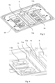
- the Fig. 2 shows the vehicle hatch assembly 100 in an isometric view from the bottom side.
- the housing 2 has bottom plate 34 with at least one air inlet 3 and at least one air outlet 4.
- the housing 2 is shaped to define internal volume for air.
- the housing 2 is air-tight between the air inlet 3 and the air outlet 4.
- the housing 2 has substantially a flattened cuboid shape. It may have closing members 26 for removable fixing of the cover 33 to the bottom plate 34.
- Fig. 3 shows the vehicle hatch assembly 100 in an isometric view from the top side with top cover 33 removed.
- the vehicle hatch assembly 100 comprises at least one air propulsion device 5a, 5b configured to force the air movement between the air inlet 3 and the air outlet 4.
- it may be in form of a known blower. According to needs, the number and configuration of air propulsion devices 5a, 5b may vary. In the examples shown in the figures, there are two first air propulsion devices 5a at the air inlet 3 and two second air propulsion devices 5b at the air outlet 4.
- the vehicle hatch assembly 100 further comprises a UV light source 6, located within the housing 2 between the air inlet 3 and the air outlet 4.
- the UV light source 6 is located therebetween.
- the UV light source 6 produces UV-C light with 254nm wavelength. This wavelength has been proven to be optimal for neutralizing harmful viruses, for example Covid-19.
- the vehicle hatch assembly 100 further comprises at least one light trap 10a, 10b, preferably two, configured to prevent the UV light from escaping the housing 2 through the air inlet 3 and/or the air outlet 4.
- the housing 2 may comprise an electrical ballast for the UV light source 6, as well as an electronic control unit.
- any light trap 10a, 10b directly faces the UV light source 6.
- the size of the vehicle hatch assembly 100 can be optimized for an efficient operation with a compact packaging.
- the assembly comprises a first light trap 10a arranged between the UV light source 6 and the first air propulsion device 5a and a second light trap 10b arranged between the UV light source 6 and the second air propulsion device 5b.
- Fig. 4 shows an enlarged portion of the view of Fig. 4 .
- the first light trap 10a has a first wall 11a and a second wall 12a extending in parallel to each other at a distance.
- the first wall 11a comprises first air openings 13 and the second wall 12a comprises second air openings 14.
- the first air openings 13 are shifted with respect to the second air openings 14 in a direction perpendicular to the extension direction of the first wall 11a and the second wall 12a.
- the second light trap 10b is configured analogously in order to protect the second propulsion device 5b and the outlet 4. Consequently, the passengers are safe from harmful direct exposure.
- the light trap 10a, 10b comprises a UV protection coating.
- a black matte powder coating is a black matte powder coating.
- Fig. 5 shows schematically side view of another embodiment of the invention.
- the air inlet 3 and the air outlet 4 are located on a first side A of the vehicle hatch assembly 100.
- the vehicle hatch assembly 100 may be configured to exchange air with a second side B of the vehicle hatch assembly 100 located in an opposite way with respect to the first side A. It may comprise an opening arrangement 20 configured as air inlet and/or outlet, with dedicated air propulsion means 21 to force air movement between the first side A and the second side B through the vehicle hatch assembly 100. In this manner, the vehicle hatch assembly 100 may draw fresh air from the outside and/or expel air from the inside of the vehicle. It may further comprise a window section 30 configured to at least partly transmit light between the first side A and the second side B.
- Figs. 6a and 6b show schematically side view of the vehicle hatch assembly in a closed and open position.
- the vehicle hatch assembly 100 may be an emergency exit hatch, comprising a door 35 adapted for switching between a closed position, shown in Fig. 6a , and an opened position, shown in Fig. 6b .
- the vehicle hatch assembly 100 according to invention can be easily placed in most such existing vehicles. Because the vehicle hatch assembly 100 is allowed to have standard frame, it can be mounted in already existing roof openings without any substantial modification. The vehicle hatch assembly 100 according to invention does not take any additional space on the vehicle and additional purification units are not needed to ensure that the air circulating within the bus is purified.
- the invention solves the space requirement, substantially reduces the number of components in the vehicle and saves weight.
- the invention can be implemented in several ways and on several bases: a mere emergency exit door, ventilation hatch, light-providing window etc.
Landscapes
- Engineering & Computer Science (AREA)
- Mechanical Engineering (AREA)
- Thermal Sciences (AREA)
- Physics & Mathematics (AREA)
- Health & Medical Sciences (AREA)
- Animal Behavior & Ethology (AREA)
- Veterinary Medicine (AREA)
- Public Health (AREA)
- General Health & Medical Sciences (AREA)
- Life Sciences & Earth Sciences (AREA)
- Epidemiology (AREA)
- Air-Conditioning For Vehicles (AREA)
- Lighting Device Outwards From Vehicle And Optical Signal (AREA)
Description
- The invention relates to a vehicle hatch assembly, in particular to a vehicle hatch assembly adapted for air purification.
- There is a constant need for conditioning of the air used for breathing in closed spaces. This relates to stationary spaces, like housing or office rooms, as well as to passenger transportation means, such as road vehicles, airplanes, ships etc. In this context, in addition to humidity and temperature, air quality is also an important parameter for comfort and safety of users. The air circulating within a closed space degrades over time as it is breathed in and out by users. Presence of viruses, bacteria, fungi has a negative influence on health of the passengers.
- It has been known to utilize UV light sources for purification of air thanks to their germicidal properties. UV-C light, i.e. ultraviolet radiation with wavelength between 100 and 280 nm, is particularly effective at disrupting DNA of viruses such as COVID-19, so that the virus can no longer reproduce itself. However, implementation of UV light sources usually is problematic in view of safety. The beneficial effect of destroying viruses, bacteria and fungi can easily be harmful to users if they are subject to direct exposure to UV radiation. In general, utilization of UV light sources for purification on air is problematic in terms of space, cost and reliability concerns, especially for mobile applications.
- Vehicles used for transportation of multiple passengers, for example buses, have significant need for supply a fresh and clean air for breathing. Additional devices mounted within the passenger compartment are known to be applied in such vehicles, in particular for purifying air to remove any viruses. These however occupy space, which could otherwise be dedicated for passengers comfort. Additionally, they require additional mounting arrangements and intrusion into existing structure and design of the vehicle.
- A vehicle hatch assembly adapted to be mounted in a vehicle are known from
JP2002178745 EP3943117 . - It would be desirable to provide an air purification device, which would at least partly alleviate the above-mentioned problems.
- The object of the invention is, a vehicle hatch assembly according to claim 1, adapted to be mounted in a vehicle, wherein it comprises a housing and at least one air inlet and at least one air outlet, an air propulsion device configured to force the air movement between the air inlet and the air outlet, and a UV light source located within the housing between the air inlet and the air outlet.
- Preferably, the air inlet and the air outlet are located on a first side of the vehicle hatch assembly, the vehicle hatch assembly being configured to exchange air with a second side of the vehicle hatch assembly located in an opposite way with respect to the first side.
- Preferably, it comprises an opening arrangement configured as air inlet and/or outlet, comprising dedicated air propulsion means to force air movement between the first side and the second side through the vehicle hatch assembly.
- Preferably, it further comprises a window section configured to at least partly transmit light between the first side and the second side.
- According to the invention, it comprises at least one light trap configured to prevent the UV light from escaping the housing through the air inlet and/or the air outlet.
- Preferably, the light trap has a first wall and a second wall extending in parallel to each other at a distance, wherein the first wall comprises first air openings and the second wall comprises second air openings, the first air openings being shifted with respect to the second air openings in a direction perpendicular to the extension direction of the first wall and the second wall.
- Preferably, it comprises a first air propulsion device dedicated for the air inlet and a second air propulsion device dedicated for the air outlet, wherein the UV light source is located therebetween.
- Preferably, it comprises a first light trap arranged between the UV light source and the first air propulsion device and a second light trap arranged between the UV light source and the second air propulsion device.
- Preferably, any light trap comprises a UV protection coating.
- Preferably, the coating is a black matte powder coating.
- Preferably, it is an emergency exit hatch, comprising a door adapted for switching between a closed position and an opened position.
- Preferably, it comprises an emergency handle adapted for opening and closing the vehicle hatch assembly.
- Another object of the invention is a vehicle, in particular a bus, comprising a vehicle hatch assembly according to any of claims 1 to 11.
- Examples of the invention will be apparent from and described in detail with reference to the accompanying drawings, in which:
-
Fig. 1 shows the vehicle hatch assembly in an isometric view from the top side; -
Fig. 2 shows the vehicle hatch assembly in an isometric view from the bottom side; -
Fig. 3 shows the vehicle hatch assembly in an isometric view from the top side with top cover removed; -
Fig. 4 shows an enlarged portion of the view ofFig. 4 ; -
Fig. 5 shows schematically side view of another embodiment of the invention; -
Figs. 6a and 6b show schematically side view of the vehicle hatch assembly in a closed and open position. -
Fig. 1 shows thevehicle hatch assembly 100 in an isometric view from the top side. The vehicle hatch assembly comprises ahousing 2 with atop cover 33. Optionally, it may comprise anemergency handle 25 adapted for opening and closing the assembly. Thevehicle hatch assembly 100 is configured to be mounted in place of traditional hatch assembly in a roof of a vehicle, e.g. bus, in a known manner. - The
Fig. 2 shows thevehicle hatch assembly 100 in an isometric view from the bottom side. Thehousing 2 hasbottom plate 34 with at least oneair inlet 3 and at least oneair outlet 4. Thehousing 2 is shaped to define internal volume for air. Preferably, thehousing 2 is air-tight between theair inlet 3 and theair outlet 4. In the shown case, thehousing 2 has substantially a flattened cuboid shape. It may have closingmembers 26 for removable fixing of thecover 33 to thebottom plate 34. -
Fig. 3 shows thevehicle hatch assembly 100 in an isometric view from the top side withtop cover 33 removed. Thevehicle hatch assembly 100 comprises at least oneair propulsion device air inlet 3 and theair outlet 4. In this case, it may be in form of a known blower. According to needs, the number and configuration ofair propulsion devices air propulsion devices 5a at theair inlet 3 and two secondair propulsion devices 5b at theair outlet 4. Thevehicle hatch assembly 100 further comprises aUV light source 6, located within thehousing 2 between theair inlet 3 and theair outlet 4. Preferably, there is a firstair propulsion device 5a dedicated for theair inlet 3 and a secondair propulsion device 5b dedicated for theair outlet 4, wherein theUV light source 6 is located therebetween. By providing aUV light source 6, the air travelling between theair inlet 3 and theair outlet 4 is subject to UV radiation so that airborne mold bacteria can be killed, and viruses floating in the air can be inactivated. Consequently, the air leaving thevehicle hatch assembly 100 is safe for users. Preferably, theUV light source 6 produces UV-C light with 254nm wavelength. This wavelength has been proven to be optimal for neutralizing harmful viruses, for example Covid-19. Thevehicle hatch assembly 100 further comprises at least onelight trap housing 2 through theair inlet 3 and/or theair outlet 4. Thehousing 2 may comprise an electrical ballast for the UVlight source 6, as well as an electronic control unit. - Preferably, any
light trap light source 6. In this way, the size of thevehicle hatch assembly 100 can be optimized for an efficient operation with a compact packaging. In the shown example, the assembly comprises afirst light trap 10a arranged between the UVlight source 6 and the firstair propulsion device 5a and a secondlight trap 10b arranged between the UVlight source 6 and the secondair propulsion device 5b. -
Fig. 4 shows an enlarged portion of the view ofFig. 4 . As it can be seen, thefirst light trap 10a has afirst wall 11a and asecond wall 12a extending in parallel to each other at a distance. Thefirst wall 11a comprisesfirst air openings 13 and thesecond wall 12a comprisessecond air openings 14. Thefirst air openings 13 are shifted with respect to thesecond air openings 14 in a direction perpendicular to the extension direction of thefirst wall 11a and thesecond wall 12a. In this manner, the UV light is prevented from directly reaching thepropulsion device 5a and theinlet 3. The secondlight trap 10b is configured analogously in order to protect thesecond propulsion device 5b and theoutlet 4. Consequently, the passengers are safe from harmful direct exposure. Preferably, thelight trap -
Fig. 5 shows schematically side view of another embodiment of the invention. Theair inlet 3 and theair outlet 4 are located on a first side A of thevehicle hatch assembly 100. Thevehicle hatch assembly 100 may be configured to exchange air with a second side B of thevehicle hatch assembly 100 located in an opposite way with respect to the first side A. It may comprise anopening arrangement 20 configured as air inlet and/or outlet, with dedicated air propulsion means 21 to force air movement between the first side A and the second side B through thevehicle hatch assembly 100. In this manner, thevehicle hatch assembly 100 may draw fresh air from the outside and/or expel air from the inside of the vehicle. It may further comprise awindow section 30 configured to at least partly transmit light between the first side A and the second side B. -
Figs. 6a and 6b show schematically side view of the vehicle hatch assembly in a closed and open position. Thevehicle hatch assembly 100 may be an emergency exit hatch, comprising adoor 35 adapted for switching between a closed position, shown inFig. 6a , and an opened position, shown inFig. 6b . - Because any bus has an emergency exit hatch as default, the
vehicle hatch assembly 100 according to invention can be easily placed in most such existing vehicles. Because thevehicle hatch assembly 100 is allowed to have standard frame, it can be mounted in already existing roof openings without any substantial modification. Thevehicle hatch assembly 100 according to invention does not take any additional space on the vehicle and additional purification units are not needed to ensure that the air circulating within the bus is purified. - The invention solves the space requirement, substantially reduces the number of components in the vehicle and saves weight. The invention can be implemented in several ways and on several bases: a mere emergency exit door, ventilation hatch, light-providing window etc.
- Other variations to the disclosed embodiments can be understood and effected by those skilled in the art in practicing the claimed invention, from a study of drawings, the disclosure, and within the scope of the appended claims. The mere fact that certain measures are recited in mutually different dependent claims does not indicate that a combination of these measures cannot be used to the advantage.
Claims (12)
- A vehicle hatch assembly (100) adapted to be mounted in a vehicle, and comprises a housing (2) and at least one air inlet (3) and at least one air outlet (4), an air propulsion device (5a, 5b) configured to force the air movement between the air inlet (3) and the air outlet (4), and a UV light source (6) located within the housing (2) between the air inlet (3) and the air outlet (4) characterized in that it further comprises at least one light trap (10a, 10b) configured to prevent the UV light from escaping the housing (2) through the air inlet (3) and/or the air outlet (4).
- A vehicle hatch assembly (100) according to claim 1, wherein the air inlet (3) and the air outlet (4) are located on a first side (A) of the vehicle hatch assembly (100), the vehicle hatch assembly (100) being configured to exchange air with a second side (B) of the vehicle hatch assembly (100) located in an opposite way with respect to the first side (A).
- A vehicle hatch assembly (100) according to claim 2, wherein it comprises an opening arrangement (20) configured as air inlet and/or outlet, comprising dedicated air propulsion means (21) to force air movement between the first side (A) and the second side (B) through the vehicle hatch assembly (100).
- A vehicle hatch assembly (100) according to any preceding claim, wherein it further comprises a window section (30) configured to at least partly transmit light between the first side (A) and the second side (B).
- A vehicle hatch assembly according to any preceding claim, wherein the light trap (10a, 10b) has a first wall (11a) and a second wall (12a) extending in parallel to each other at a distance, wherein the first wall (11a) comprises first air openings (13) and the second wall (12a) comprises second air openings (14), the first air openings (13) being shifted with respect to the second air openings (14) in a direction perpendicular to the extension direction of the first wall (11a) and the second wall (12a).
- A vehicle hatch assembly according to any preceding claim, comprising a first air propulsion device (5a) dedicated for the air inlet (3) and a second air propulsion device (5b) dedicated for the air outlet (4), wherein the UV light source (6) is located therebetween.
- A vehicle hatch assembly according to claim 6, comprising a first light trap (10a) arranged between the UV light source (6) and the first air propulsion device (5a) and a second light trap (10b) arranged between the UV light source (6) and the second air propulsion device (5b).
- A vehicle hatch assembly according to any preceding claim, wherein any light trap (10a, 10b) comprises a UV protection coating.
- A vehicle hatch assembly according to the preceding claim, wherein the coating is a black matte powder coating.
- A vehicle hatch assembly (100) according to claim 1, wherein it is an emergency exit hatch, comprising a door (35) adapted for switching between a closed position and an opened position.
- A vehicle hatch assembly (100) according to claim 10, wherein it comprises an emergency handle (25) adapted for opening and closing the vehicle hatch assembly (100).
- A vehicle, in particular a bus, comprising a vehicle hatch assembly (100) according to any preceding claim.
Priority Applications (5)
| Application Number | Priority Date | Filing Date | Title |
|---|---|---|---|
| HUE21215574A HUE071634T2 (en) | 2021-12-17 | 2021-12-17 | A vehicle hatch assembly |
| FIEP21215574.1T FI4197833T3 (en) | 2021-12-17 | 2021-12-17 | A vehicle hatch assembly |
| PL21215574.1T PL4197833T3 (en) | 2021-12-17 | 2021-12-17 | A vehicle hatch assembly |
| ES21215574T ES2995242T3 (en) | 2021-12-17 | 2021-12-17 | A vehicle hatch assembly |
| EP21215574.1A EP4197833B1 (en) | 2021-12-17 | 2021-12-17 | A vehicle hatch assembly |
Applications Claiming Priority (1)
| Application Number | Priority Date | Filing Date | Title |
|---|---|---|---|
| EP21215574.1A EP4197833B1 (en) | 2021-12-17 | 2021-12-17 | A vehicle hatch assembly |
Publications (2)
| Publication Number | Publication Date |
|---|---|
| EP4197833A1 EP4197833A1 (en) | 2023-06-21 |
| EP4197833B1 true EP4197833B1 (en) | 2024-09-04 |
Family
ID=78957195
Family Applications (1)
| Application Number | Title | Priority Date | Filing Date |
|---|---|---|---|
| EP21215574.1A Active EP4197833B1 (en) | 2021-12-17 | 2021-12-17 | A vehicle hatch assembly |
Country Status (5)
| Country | Link |
|---|---|
| EP (1) | EP4197833B1 (en) |
| ES (1) | ES2995242T3 (en) |
| FI (1) | FI4197833T3 (en) |
| HU (1) | HUE071634T2 (en) |
| PL (1) | PL4197833T3 (en) |
Family Cites Families (3)
| Publication number | Priority date | Publication date | Assignee | Title |
|---|---|---|---|---|
| KR100343569B1 (en) * | 1999-10-27 | 2002-07-19 | 현대자동차주식회사 | Roof ventilators for closed vehicle |
| JP2002178745A (en) * | 2000-12-14 | 2002-06-26 | Denso Corp | Vehicle air purifier |
| EP3943117A1 (en) * | 2020-07-22 | 2022-01-26 | Inalfa Roof Systems Group B.V. | Method and system for disinfection of a vehicle interior |
-
2021
- 2021-12-17 EP EP21215574.1A patent/EP4197833B1/en active Active
- 2021-12-17 ES ES21215574T patent/ES2995242T3/en active Active
- 2021-12-17 PL PL21215574.1T patent/PL4197833T3/en unknown
- 2021-12-17 FI FIEP21215574.1T patent/FI4197833T3/en active
- 2021-12-17 HU HUE21215574A patent/HUE071634T2/en unknown
Also Published As
| Publication number | Publication date |
|---|---|
| HUE071634T2 (en) | 2025-09-28 |
| ES2995242T3 (en) | 2025-02-07 |
| EP4197833A1 (en) | 2023-06-21 |
| FI4197833T3 (en) | 2024-09-19 |
| PL4197833T3 (en) | 2025-03-03 |
Similar Documents
| Publication | Publication Date | Title |
|---|---|---|
| BR0000135A (en) | Ventilation system for vehicle window | |
| RU78074U1 (en) | UNIT FOR DISINFECTION OF AIR BY UV RADIATION | |
| RU143401U1 (en) | INSTALLATION FOR DISINFECTING AIR BY UV RADIATION IN A PASSENGER CAR (OPTIONS) | |
| KR102299070B1 (en) | Book sterilizer with movable book rack | |
| RU143645U1 (en) | UNIT FOR DISINFECTION OF AIR BY UV RADIATION IN ELECTRIC TRAIN CARS | |
| EP3369595A1 (en) | Railway car air conditioning system | |
| RU189481U1 (en) | Installation for air disinfection | |
| EP4197833B1 (en) | A vehicle hatch assembly | |
| LV13780B (en) | Railway vehicle ventilation and air-conditioning system | |
| KR102444444B1 (en) | Photocatalyst device and air conditioner including same | |
| RU182391U1 (en) | Air disinfection unit | |
| CN114228447A (en) | Catalyst device and vehicle air conditioner including the same | |
| US20220144038A1 (en) | Systems and methods useful for air treatment in a vehicle | |
| WO2017142137A1 (en) | Vehicle air conditioning system | |
| RU188578U1 (en) | Installation for air disinfection | |
| EP2682320B1 (en) | Device for disinfecting the air in underground railway carriages | |
| RU183709U1 (en) | Air disinfection unit | |
| KR102226005B1 (en) | Photocatalyst device | |
| KR102219740B1 (en) | Air conditioner for vehicle | |
| WO2022128109A1 (en) | An air purification device with a uv light source | |
| CN214822499U (en) | Automobile and air conditioner sterilizing device thereof | |
| RU201953U1 (en) | Air disinfection unit with UV radiation | |
| RU134879U1 (en) | VENTILATION AIR DISINFECTION SYSTEM USING UV LAMPS | |
| RU186627U1 (en) | Installation for air disinfection by UV radiation in the ventilation and air conditioning system of subway cars | |
| JPH0645198Y2 (en) | Ventilation and equipment cooling system for passenger compartment in combat vehicle |
Legal Events
| Date | Code | Title | Description |
|---|---|---|---|
| PUAI | Public reference made under article 153(3) epc to a published international application that has entered the european phase |
Free format text: ORIGINAL CODE: 0009012 |
|
| STAA | Information on the status of an ep patent application or granted ep patent |
Free format text: STATUS: THE APPLICATION HAS BEEN PUBLISHED |
|
| AK | Designated contracting states |
Kind code of ref document: A1 Designated state(s): AL AT BE BG CH CY CZ DE DK EE ES FI FR GB GR HR HU IE IS IT LI LT LU LV MC MK MT NL NO PL PT RO RS SE SI SK SM TR |
|
| STAA | Information on the status of an ep patent application or granted ep patent |
Free format text: STATUS: REQUEST FOR EXAMINATION WAS MADE |
|
| 17P | Request for examination filed |
Effective date: 20231218 |
|
| RBV | Designated contracting states (corrected) |
Designated state(s): AL AT BE BG CH CY CZ DE DK EE ES FI FR GB GR HR HU IE IS IT LI LT LU LV MC MK MT NL NO PL PT RO RS SE SI SK SM TR |
|
| GRAP | Despatch of communication of intention to grant a patent |
Free format text: ORIGINAL CODE: EPIDOSNIGR1 |
|
| STAA | Information on the status of an ep patent application or granted ep patent |
Free format text: STATUS: GRANT OF PATENT IS INTENDED |
|
| INTG | Intention to grant announced |
Effective date: 20240507 |
|
| RIC1 | Information provided on ipc code assigned before grant |
Ipc: A61L 9/20 20060101ALI20240419BHEP Ipc: B60J 7/16 20060101ALI20240419BHEP Ipc: B60H 1/00 20060101ALI20240419BHEP Ipc: B60H 3/00 20060101ALI20240419BHEP Ipc: B60H 1/26 20060101AFI20240419BHEP |
|
| GRAS | Grant fee paid |
Free format text: ORIGINAL CODE: EPIDOSNIGR3 |
|
| GRAA | (expected) grant |
Free format text: ORIGINAL CODE: 0009210 |
|
| STAA | Information on the status of an ep patent application or granted ep patent |
Free format text: STATUS: THE PATENT HAS BEEN GRANTED |
|
| AK | Designated contracting states |
Kind code of ref document: B1 Designated state(s): AL AT BE BG CH CY CZ DE DK EE ES FI FR GB GR HR HU IE IS IT LI LT LU LV MC MK MT NL NO PL PT RO RS SE SI SK SM TR |
|
| REG | Reference to a national code |
Ref country code: DE Ref legal event code: R081 Ref document number: 602021018258 Country of ref document: DE Owner name: SPHEROS GERMANY GMBH, DE Free format text: FORMER OWNER: ANMELDERANGABEN UNKLAR / UNVOLLSTAENDIG, 80297 MUENCHEN, DE Ref country code: DE Ref legal event code: R081 Ref document number: 602021018258 Country of ref document: DE Owner name: VALEO THERMAL COMMERCIAL VEHICLES GERMANY GMBH, DE Free format text: FORMER OWNER: ANMELDERANGABEN UNKLAR / UNVOLLSTAENDIG, 80297 MUENCHEN, DE Ref country code: GB Ref legal event code: FG4D |
|
| REG | Reference to a national code |
Ref country code: DE Ref legal event code: R081 Ref document number: 602021018258 Country of ref document: DE Owner name: SPHEROS GERMANY GMBH, DE Free format text: FORMER OWNER: VALEO THERMAL COMMERCIAL VEHICLES GERMANY GMBH, 82205 GILCHING, DE |
|
| REG | Reference to a national code |
Ref country code: CH Ref legal event code: EP |
|
| REG | Reference to a national code |
Ref country code: FI Ref legal event code: FGE |
|
| REG | Reference to a national code |
Ref country code: IE Ref legal event code: FG4D |
|
| REG | Reference to a national code |
Ref country code: DE Ref legal event code: R096 Ref document number: 602021018258 Country of ref document: DE |
|
| REG | Reference to a national code |
Ref country code: LT Ref legal event code: MG9D |
|
| REG | Reference to a national code |
Ref country code: NL Ref legal event code: MP Effective date: 20240904 |
|
| PG25 | Lapsed in a contracting state [announced via postgrant information from national office to epo] |
Ref country code: NO Free format text: LAPSE BECAUSE OF FAILURE TO SUBMIT A TRANSLATION OF THE DESCRIPTION OR TO PAY THE FEE WITHIN THE PRESCRIBED TIME-LIMIT Effective date: 20241204 |
|
| PG25 | Lapsed in a contracting state [announced via postgrant information from national office to epo] |
Ref country code: GR Free format text: LAPSE BECAUSE OF FAILURE TO SUBMIT A TRANSLATION OF THE DESCRIPTION OR TO PAY THE FEE WITHIN THE PRESCRIBED TIME-LIMIT Effective date: 20241205 |
|
| PGFP | Annual fee paid to national office [announced via postgrant information from national office to epo] |
Ref country code: FI Payment date: 20241216 Year of fee payment: 4 |
|
| PG25 | Lapsed in a contracting state [announced via postgrant information from national office to epo] |
Ref country code: BG Free format text: LAPSE BECAUSE OF FAILURE TO SUBMIT A TRANSLATION OF THE DESCRIPTION OR TO PAY THE FEE WITHIN THE PRESCRIBED TIME-LIMIT Effective date: 20240904 |
|
| PG25 | Lapsed in a contracting state [announced via postgrant information from national office to epo] |
Ref country code: LV Free format text: LAPSE BECAUSE OF FAILURE TO SUBMIT A TRANSLATION OF THE DESCRIPTION OR TO PAY THE FEE WITHIN THE PRESCRIBED TIME-LIMIT Effective date: 20240904 |
|
| PG25 | Lapsed in a contracting state [announced via postgrant information from national office to epo] |
Ref country code: HR Free format text: LAPSE BECAUSE OF FAILURE TO SUBMIT A TRANSLATION OF THE DESCRIPTION OR TO PAY THE FEE WITHIN THE PRESCRIBED TIME-LIMIT Effective date: 20240904 |
|
| PG25 | Lapsed in a contracting state [announced via postgrant information from national office to epo] |
Ref country code: NO Free format text: LAPSE BECAUSE OF FAILURE TO SUBMIT A TRANSLATION OF THE DESCRIPTION OR TO PAY THE FEE WITHIN THE PRESCRIBED TIME-LIMIT Effective date: 20241204 Ref country code: LV Free format text: LAPSE BECAUSE OF FAILURE TO SUBMIT A TRANSLATION OF THE DESCRIPTION OR TO PAY THE FEE WITHIN THE PRESCRIBED TIME-LIMIT Effective date: 20240904 Ref country code: HR Free format text: LAPSE BECAUSE OF FAILURE TO SUBMIT A TRANSLATION OF THE DESCRIPTION OR TO PAY THE FEE WITHIN THE PRESCRIBED TIME-LIMIT Effective date: 20240904 Ref country code: GR Free format text: LAPSE BECAUSE OF FAILURE TO SUBMIT A TRANSLATION OF THE DESCRIPTION OR TO PAY THE FEE WITHIN THE PRESCRIBED TIME-LIMIT Effective date: 20241205 Ref country code: BG Free format text: LAPSE BECAUSE OF FAILURE TO SUBMIT A TRANSLATION OF THE DESCRIPTION OR TO PAY THE FEE WITHIN THE PRESCRIBED TIME-LIMIT Effective date: 20240904 |
|
| REG | Reference to a national code |
Ref country code: ES Ref legal event code: FG2A Ref document number: 2995242 Country of ref document: ES Kind code of ref document: T3 Effective date: 20250207 |
|
| REG | Reference to a national code |
Ref country code: AT Ref legal event code: MK05 Ref document number: 1720019 Country of ref document: AT Kind code of ref document: T Effective date: 20240904 |
|
| PG25 | Lapsed in a contracting state [announced via postgrant information from national office to epo] |
Ref country code: NL Free format text: LAPSE BECAUSE OF FAILURE TO SUBMIT A TRANSLATION OF THE DESCRIPTION OR TO PAY THE FEE WITHIN THE PRESCRIBED TIME-LIMIT Effective date: 20240904 |
|
| PG25 | Lapsed in a contracting state [announced via postgrant information from national office to epo] |
Ref country code: IS Free format text: LAPSE BECAUSE OF FAILURE TO SUBMIT A TRANSLATION OF THE DESCRIPTION OR TO PAY THE FEE WITHIN THE PRESCRIBED TIME-LIMIT Effective date: 20250104 Ref country code: PT Free format text: LAPSE BECAUSE OF FAILURE TO SUBMIT A TRANSLATION OF THE DESCRIPTION OR TO PAY THE FEE WITHIN THE PRESCRIBED TIME-LIMIT Effective date: 20250106 |
|
| PGFP | Annual fee paid to national office [announced via postgrant information from national office to epo] |
Ref country code: DE Payment date: 20250301 Year of fee payment: 4 |
|
| PG25 | Lapsed in a contracting state [announced via postgrant information from national office to epo] |
Ref country code: RO Free format text: LAPSE BECAUSE OF FAILURE TO SUBMIT A TRANSLATION OF THE DESCRIPTION OR TO PAY THE FEE WITHIN THE PRESCRIBED TIME-LIMIT Effective date: 20240904 Ref country code: SM Free format text: LAPSE BECAUSE OF FAILURE TO SUBMIT A TRANSLATION OF THE DESCRIPTION OR TO PAY THE FEE WITHIN THE PRESCRIBED TIME-LIMIT Effective date: 20240904 |
|
| PGFP | Annual fee paid to national office [announced via postgrant information from national office to epo] |
Ref country code: ES Payment date: 20250117 Year of fee payment: 4 |
|
| PG25 | Lapsed in a contracting state [announced via postgrant information from national office to epo] |
Ref country code: EE Free format text: LAPSE BECAUSE OF FAILURE TO SUBMIT A TRANSLATION OF THE DESCRIPTION OR TO PAY THE FEE WITHIN THE PRESCRIBED TIME-LIMIT Effective date: 20240904 Ref country code: AT Free format text: LAPSE BECAUSE OF FAILURE TO SUBMIT A TRANSLATION OF THE DESCRIPTION OR TO PAY THE FEE WITHIN THE PRESCRIBED TIME-LIMIT Effective date: 20240904 |
|
| PGFP | Annual fee paid to national office [announced via postgrant information from national office to epo] |
Ref country code: CZ Payment date: 20241205 Year of fee payment: 4 Ref country code: PL Payment date: 20241205 Year of fee payment: 4 |
|
| PG25 | Lapsed in a contracting state [announced via postgrant information from national office to epo] |
Ref country code: SK Free format text: LAPSE BECAUSE OF FAILURE TO SUBMIT A TRANSLATION OF THE DESCRIPTION OR TO PAY THE FEE WITHIN THE PRESCRIBED TIME-LIMIT Effective date: 20240904 Ref country code: IT Free format text: LAPSE BECAUSE OF FAILURE TO SUBMIT A TRANSLATION OF THE DESCRIPTION OR TO PAY THE FEE WITHIN THE PRESCRIBED TIME-LIMIT Effective date: 20240904 |
|
| PGFP | Annual fee paid to national office [announced via postgrant information from national office to epo] |
Ref country code: TR Payment date: 20241210 Year of fee payment: 4 |
|
| REG | Reference to a national code |
Ref country code: DE Ref legal event code: R097 Ref document number: 602021018258 Country of ref document: DE |
|
| PG25 | Lapsed in a contracting state [announced via postgrant information from national office to epo] |
Ref country code: RS Free format text: LAPSE BECAUSE OF FAILURE TO SUBMIT A TRANSLATION OF THE DESCRIPTION OR TO PAY THE FEE WITHIN THE PRESCRIBED TIME-LIMIT Effective date: 20240904 |
|
| RAP4 | Party data changed (patent owner data changed or rights of a patent transferred) |
Owner name: SPHEROS GERMANY GMBH |
|
| PG25 | Lapsed in a contracting state [announced via postgrant information from national office to epo] |
Ref country code: MC Free format text: LAPSE BECAUSE OF FAILURE TO SUBMIT A TRANSLATION OF THE DESCRIPTION OR TO PAY THE FEE WITHIN THE PRESCRIBED TIME-LIMIT Effective date: 20240904 |
|
| PG25 | Lapsed in a contracting state [announced via postgrant information from national office to epo] |
Ref country code: DK Free format text: LAPSE BECAUSE OF FAILURE TO SUBMIT A TRANSLATION OF THE DESCRIPTION OR TO PAY THE FEE WITHIN THE PRESCRIBED TIME-LIMIT Effective date: 20240904 |
|
| PLBE | No opposition filed within time limit |
Free format text: ORIGINAL CODE: 0009261 |
|
| STAA | Information on the status of an ep patent application or granted ep patent |
Free format text: STATUS: NO OPPOSITION FILED WITHIN TIME LIMIT |
|
| PGFP | Annual fee paid to national office [announced via postgrant information from national office to epo] |
Ref country code: HU Payment date: 20250115 Year of fee payment: 4 |
|
| REG | Reference to a national code |
Ref country code: HU Ref legal event code: HC9C Owner name: SPHEROS GERMANY GMBH, DE Free format text: FORMER OWNER(S): VALEO THERMAL COMMERCIAL VEHICLES GERMANY GMBH, DE |
|
| REG | Reference to a national code |
Ref country code: CH Ref legal event code: PL |
|
| 26N | No opposition filed |
Effective date: 20250605 |
|
| PG25 | Lapsed in a contracting state [announced via postgrant information from national office to epo] |
Ref country code: LU Free format text: LAPSE BECAUSE OF NON-PAYMENT OF DUE FEES Effective date: 20241217 |
|
| PG25 | Lapsed in a contracting state [announced via postgrant information from national office to epo] |
Ref country code: SE Free format text: LAPSE BECAUSE OF FAILURE TO SUBMIT A TRANSLATION OF THE DESCRIPTION OR TO PAY THE FEE WITHIN THE PRESCRIBED TIME-LIMIT Effective date: 20240904 |
|
| REG | Reference to a national code |
Ref country code: HU Ref legal event code: AG4A Ref document number: E071634 Country of ref document: HU |
|
| REG | Reference to a national code |
Ref country code: BE Ref legal event code: MM Effective date: 20241231 |
|
| PG25 | Lapsed in a contracting state [announced via postgrant information from national office to epo] |
Ref country code: BE Free format text: LAPSE BECAUSE OF NON-PAYMENT OF DUE FEES Effective date: 20241231 |
|
| PG25 | Lapsed in a contracting state [announced via postgrant information from national office to epo] |
Ref country code: FR Free format text: LAPSE BECAUSE OF NON-PAYMENT OF DUE FEES Effective date: 20241231 |
|
| PG25 | Lapsed in a contracting state [announced via postgrant information from national office to epo] |
Ref country code: CH Free format text: LAPSE BECAUSE OF NON-PAYMENT OF DUE FEES Effective date: 20241231 |
|
| PG25 | Lapsed in a contracting state [announced via postgrant information from national office to epo] |
Ref country code: IE Free format text: LAPSE BECAUSE OF NON-PAYMENT OF DUE FEES Effective date: 20241217 |