EP4197828B1 - Fahrzeugluftsteuerungssystem und verfahren zum steuern eines fahrzeugluftsteuerungssystem - Google Patents
Fahrzeugluftsteuerungssystem und verfahren zum steuern eines fahrzeugluftsteuerungssystem Download PDFInfo
- Publication number
- EP4197828B1 EP4197828B1 EP21214836.5A EP21214836A EP4197828B1 EP 4197828 B1 EP4197828 B1 EP 4197828B1 EP 21214836 A EP21214836 A EP 21214836A EP 4197828 B1 EP4197828 B1 EP 4197828B1
- Authority
- EP
- European Patent Office
- Prior art keywords
- air
- tank
- boost
- valve
- management system
- Prior art date
- Legal status (The legal status is an assumption and is not a legal conclusion. Google has not performed a legal analysis and makes no representation as to the accuracy of the status listed.)
- Active
Links
Images

Classifications
-
- B—PERFORMING OPERATIONS; TRANSPORTING
- B60—VEHICLES IN GENERAL
- B60R—VEHICLES, VEHICLE FITTINGS, OR VEHICLE PARTS, NOT OTHERWISE PROVIDED FOR
- B60R16/00—Electric or fluid circuits specially adapted for vehicles and not otherwise provided for; Arrangement of elements of electric or fluid circuits specially adapted for vehicles and not otherwise provided for
- B60R16/08—Electric or fluid circuits specially adapted for vehicles and not otherwise provided for; Arrangement of elements of electric or fluid circuits specially adapted for vehicles and not otherwise provided for fluid
-
- B—PERFORMING OPERATIONS; TRANSPORTING
- B60—VEHICLES IN GENERAL
- B60G—VEHICLE SUSPENSION ARRANGEMENTS
- B60G17/00—Resilient suspensions having means for adjusting the spring or vibration-damper characteristics, for regulating the distance between a supporting surface and a sprung part of vehicle or for locking suspension during use to meet varying vehicular or surface conditions, e.g. due to speed or load
- B60G17/02—Spring characteristics, e.g. mechanical springs and mechanical adjusting means
- B60G17/04—Spring characteristics, e.g. mechanical springs and mechanical adjusting means fluid spring characteristics
- B60G17/052—Pneumatic spring characteristics
- B60G17/0523—Regulating distributors or valves for pneumatic springs
-
- B—PERFORMING OPERATIONS; TRANSPORTING
- B60—VEHICLES IN GENERAL
- B60T—VEHICLE BRAKE CONTROL SYSTEMS OR PARTS THEREOF; BRAKE CONTROL SYSTEMS OR PARTS THEREOF, IN GENERAL; ARRANGEMENT OF BRAKING ELEMENTS ON VEHICLES IN GENERAL; PORTABLE DEVICES FOR PREVENTING UNWANTED MOVEMENT OF VEHICLES; VEHICLE MODIFICATIONS TO FACILITATE COOLING OF BRAKES
- B60T13/00—Transmitting braking action from initiating means to ultimate brake actuator with power assistance or drive; Brake systems incorporating such transmitting means, e.g. air-pressure brake systems
- B60T13/10—Transmitting braking action from initiating means to ultimate brake actuator with power assistance or drive; Brake systems incorporating such transmitting means, e.g. air-pressure brake systems with fluid assistance, drive, or release
- B60T13/66—Electrical control in fluid-pressure brake systems
- B60T13/662—Electrical control in fluid-pressure brake systems characterised by specified functions of the control system components
-
- B—PERFORMING OPERATIONS; TRANSPORTING
- B60—VEHICLES IN GENERAL
- B60T—VEHICLE BRAKE CONTROL SYSTEMS OR PARTS THEREOF; BRAKE CONTROL SYSTEMS OR PARTS THEREOF, IN GENERAL; ARRANGEMENT OF BRAKING ELEMENTS ON VEHICLES IN GENERAL; PORTABLE DEVICES FOR PREVENTING UNWANTED MOVEMENT OF VEHICLES; VEHICLE MODIFICATIONS TO FACILITATE COOLING OF BRAKES
- B60T17/00—Component parts, details, or accessories of power brake systems not covered by groups B60T8/00, B60T13/00 or B60T15/00, or presenting other characteristic features
- B60T17/02—Arrangements of pumps or compressors, or control devices therefor
-
- F—MECHANICAL ENGINEERING; LIGHTING; HEATING; WEAPONS; BLASTING
- F04—POSITIVE - DISPLACEMENT MACHINES FOR LIQUIDS; PUMPS FOR LIQUIDS OR ELASTIC FLUIDS
- F04B—POSITIVE-DISPLACEMENT MACHINES FOR LIQUIDS; PUMPS
- F04B41/00—Pumping installations or systems specially adapted for elastic fluids
- F04B41/02—Pumping installations or systems specially adapted for elastic fluids having reservoirs
-
- F—MECHANICAL ENGINEERING; LIGHTING; HEATING; WEAPONS; BLASTING
- F04—POSITIVE - DISPLACEMENT MACHINES FOR LIQUIDS; PUMPS FOR LIQUIDS OR ELASTIC FLUIDS
- F04B—POSITIVE-DISPLACEMENT MACHINES FOR LIQUIDS; PUMPS
- F04B49/00—Control, e.g. of pump delivery, or pump pressure of, or safety measures for, machines, pumps, or pumping installations, not otherwise provided for, or of interest apart from, groups F04B1/00 - F04B47/00
- F04B49/22—Control, e.g. of pump delivery, or pump pressure of, or safety measures for, machines, pumps, or pumping installations, not otherwise provided for, or of interest apart from, groups F04B1/00 - F04B47/00 by means of valves
-
- F—MECHANICAL ENGINEERING; LIGHTING; HEATING; WEAPONS; BLASTING
- F17—STORING OR DISTRIBUTING GASES OR LIQUIDS
- F17C—VESSELS FOR CONTAINING OR STORING COMPRESSED, LIQUEFIED OR SOLIDIFIED GASES; FIXED-CAPACITY GAS-HOLDERS; FILLING VESSELS WITH, OR DISCHARGING FROM VESSELS, COMPRESSED, LIQUEFIED, OR SOLIDIFIED GASES
- F17C6/00—Methods and apparatus for filling vessels not under pressure with liquefied or solidified gases
-
- G—PHYSICS
- G05—CONTROLLING; REGULATING
- G05D—SYSTEMS FOR CONTROLLING OR REGULATING NON-ELECTRIC VARIABLES
- G05D16/00—Control of fluid pressure
- G05D16/20—Control of fluid pressure characterised by the use of electric means
- G05D16/2006—Control of fluid pressure characterised by the use of electric means with direct action of electric energy on controlling means
- G05D16/2013—Control of fluid pressure characterised by the use of electric means with direct action of electric energy on controlling means using throttling means as controlling means
-
- B—PERFORMING OPERATIONS; TRANSPORTING
- B60—VEHICLES IN GENERAL
- B60G—VEHICLE SUSPENSION ARRANGEMENTS
- B60G2300/00—Indexing codes relating to the type of vehicle
- B60G2300/02—Trucks; Load vehicles
-
- B—PERFORMING OPERATIONS; TRANSPORTING
- B60—VEHICLES IN GENERAL
- B60G—VEHICLE SUSPENSION ARRANGEMENTS
- B60G2400/00—Indexing codes relating to detected, measured or calculated conditions or factors
- B60G2400/50—Pressure
- B60G2400/51—Pressure in suspension unit
-
- B—PERFORMING OPERATIONS; TRANSPORTING
- B60—VEHICLES IN GENERAL
- B60G—VEHICLE SUSPENSION ARRANGEMENTS
- B60G2500/00—Indexing codes relating to the regulated action or device
- B60G2500/20—Spring action or springs
- B60G2500/203—Distributor valve units comprising several elements, e.g. valves, pump or accumulators
-
- B—PERFORMING OPERATIONS; TRANSPORTING
- B60—VEHICLES IN GENERAL
- B60G—VEHICLE SUSPENSION ARRANGEMENTS
- B60G2500/00—Indexing codes relating to the regulated action or device
- B60G2500/20—Spring action or springs
- B60G2500/205—Air-compressor operation
-
- F—MECHANICAL ENGINEERING; LIGHTING; HEATING; WEAPONS; BLASTING
- F04—POSITIVE - DISPLACEMENT MACHINES FOR LIQUIDS; PUMPS FOR LIQUIDS OR ELASTIC FLUIDS
- F04B—POSITIVE-DISPLACEMENT MACHINES FOR LIQUIDS; PUMPS
- F04B39/00—Component parts, details, or accessories, of pumps or pumping systems specially adapted for elastic fluids, not otherwise provided for in, or of interest apart from, groups F04B25/00 - F04B37/00
- F04B39/16—Filtration; Moisture separation
-
- F—MECHANICAL ENGINEERING; LIGHTING; HEATING; WEAPONS; BLASTING
- F15—FLUID-PRESSURE ACTUATORS; HYDRAULICS OR PNEUMATICS IN GENERAL
- F15B—SYSTEMS ACTING BY MEANS OF FLUIDS IN GENERAL; FLUID-PRESSURE ACTUATORS, e.g. SERVOMOTORS; DETAILS OF FLUID-PRESSURE SYSTEMS, NOT OTHERWISE PROVIDED FOR
- F15B2211/00—Circuits for servomotor systems
- F15B2211/60—Circuit components or control therefor
- F15B2211/63—Electronic controllers
- F15B2211/6303—Electronic controllers using input signals
- F15B2211/6306—Electronic controllers using input signals representing a pressure
-
- F—MECHANICAL ENGINEERING; LIGHTING; HEATING; WEAPONS; BLASTING
- F15—FLUID-PRESSURE ACTUATORS; HYDRAULICS OR PNEUMATICS IN GENERAL
- F15B—SYSTEMS ACTING BY MEANS OF FLUIDS IN GENERAL; FLUID-PRESSURE ACTUATORS, e.g. SERVOMOTORS; DETAILS OF FLUID-PRESSURE SYSTEMS, NOT OTHERWISE PROVIDED FOR
- F15B2211/00—Circuits for servomotor systems
- F15B2211/60—Circuit components or control therefor
- F15B2211/665—Methods of control using electronic components
- F15B2211/6653—Pressure control
-
- F—MECHANICAL ENGINEERING; LIGHTING; HEATING; WEAPONS; BLASTING
- F15—FLUID-PRESSURE ACTUATORS; HYDRAULICS OR PNEUMATICS IN GENERAL
- F15B—SYSTEMS ACTING BY MEANS OF FLUIDS IN GENERAL; FLUID-PRESSURE ACTUATORS, e.g. SERVOMOTORS; DETAILS OF FLUID-PRESSURE SYSTEMS, NOT OTHERWISE PROVIDED FOR
- F15B2211/00—Circuits for servomotor systems
- F15B2211/80—Other types of control related to particular problems or conditions
- F15B2211/885—Control specific to the type of fluid, e.g. specific to magnetorheological fluid
- F15B2211/8855—Compressible fluids, e.g. specific to pneumatics
-
- F—MECHANICAL ENGINEERING; LIGHTING; HEATING; WEAPONS; BLASTING
- F17—STORING OR DISTRIBUTING GASES OR LIQUIDS
- F17C—VESSELS FOR CONTAINING OR STORING COMPRESSED, LIQUEFIED OR SOLIDIFIED GASES; FIXED-CAPACITY GAS-HOLDERS; FILLING VESSELS WITH, OR DISCHARGING FROM VESSELS, COMPRESSED, LIQUEFIED, OR SOLIDIFIED GASES
- F17C2205/00—Vessel construction, in particular mounting arrangements, attachments or identifications means
- F17C2205/03—Fluid connections, filters, valves, closure means or other attachments
- F17C2205/0302—Fittings, valves, filters, or components in connection with the gas storage device
- F17C2205/0323—Valves
- F17C2205/0326—Valves electrically actuated
-
- F—MECHANICAL ENGINEERING; LIGHTING; HEATING; WEAPONS; BLASTING
- F17—STORING OR DISTRIBUTING GASES OR LIQUIDS
- F17C—VESSELS FOR CONTAINING OR STORING COMPRESSED, LIQUEFIED OR SOLIDIFIED GASES; FIXED-CAPACITY GAS-HOLDERS; FILLING VESSELS WITH, OR DISCHARGING FROM VESSELS, COMPRESSED, LIQUEFIED, OR SOLIDIFIED GASES
- F17C2205/00—Vessel construction, in particular mounting arrangements, attachments or identifications means
- F17C2205/03—Fluid connections, filters, valves, closure means or other attachments
- F17C2205/0302—Fittings, valves, filters, or components in connection with the gas storage device
- F17C2205/0338—Pressure regulators
-
- F—MECHANICAL ENGINEERING; LIGHTING; HEATING; WEAPONS; BLASTING
- F17—STORING OR DISTRIBUTING GASES OR LIQUIDS
- F17C—VESSELS FOR CONTAINING OR STORING COMPRESSED, LIQUEFIED OR SOLIDIFIED GASES; FIXED-CAPACITY GAS-HOLDERS; FILLING VESSELS WITH, OR DISCHARGING FROM VESSELS, COMPRESSED, LIQUEFIED, OR SOLIDIFIED GASES
- F17C2221/00—Handled fluid, in particular type of fluid
- F17C2221/03—Mixtures
- F17C2221/031—Air
-
- F—MECHANICAL ENGINEERING; LIGHTING; HEATING; WEAPONS; BLASTING
- F17—STORING OR DISTRIBUTING GASES OR LIQUIDS
- F17C—VESSELS FOR CONTAINING OR STORING COMPRESSED, LIQUEFIED OR SOLIDIFIED GASES; FIXED-CAPACITY GAS-HOLDERS; FILLING VESSELS WITH, OR DISCHARGING FROM VESSELS, COMPRESSED, LIQUEFIED, OR SOLIDIFIED GASES
- F17C2227/00—Transfer of fluids, i.e. method or means for transferring the fluid; Heat exchange with the fluid
- F17C2227/01—Propulsion of the fluid
- F17C2227/0128—Propulsion of the fluid with pumps or compressors
- F17C2227/0157—Compressors
-
- F—MECHANICAL ENGINEERING; LIGHTING; HEATING; WEAPONS; BLASTING
- F17—STORING OR DISTRIBUTING GASES OR LIQUIDS
- F17C—VESSELS FOR CONTAINING OR STORING COMPRESSED, LIQUEFIED OR SOLIDIFIED GASES; FIXED-CAPACITY GAS-HOLDERS; FILLING VESSELS WITH, OR DISCHARGING FROM VESSELS, COMPRESSED, LIQUEFIED, OR SOLIDIFIED GASES
- F17C2250/00—Accessories; Control means; Indicating, measuring or monitoring of parameters
- F17C2250/03—Control means
-
- F—MECHANICAL ENGINEERING; LIGHTING; HEATING; WEAPONS; BLASTING
- F17—STORING OR DISTRIBUTING GASES OR LIQUIDS
- F17C—VESSELS FOR CONTAINING OR STORING COMPRESSED, LIQUEFIED OR SOLIDIFIED GASES; FIXED-CAPACITY GAS-HOLDERS; FILLING VESSELS WITH, OR DISCHARGING FROM VESSELS, COMPRESSED, LIQUEFIED, OR SOLIDIFIED GASES
- F17C2250/00—Accessories; Control means; Indicating, measuring or monitoring of parameters
- F17C2250/04—Indicating or measuring of parameters as input values
- F17C2250/0404—Parameters indicated or measured
- F17C2250/0408—Level of content in the vessel
- F17C2250/0417—Level of content in the vessel with electrical means
-
- F—MECHANICAL ENGINEERING; LIGHTING; HEATING; WEAPONS; BLASTING
- F17—STORING OR DISTRIBUTING GASES OR LIQUIDS
- F17C—VESSELS FOR CONTAINING OR STORING COMPRESSED, LIQUEFIED OR SOLIDIFIED GASES; FIXED-CAPACITY GAS-HOLDERS; FILLING VESSELS WITH, OR DISCHARGING FROM VESSELS, COMPRESSED, LIQUEFIED, OR SOLIDIFIED GASES
- F17C2250/00—Accessories; Control means; Indicating, measuring or monitoring of parameters
- F17C2250/04—Indicating or measuring of parameters as input values
- F17C2250/0404—Parameters indicated or measured
- F17C2250/043—Pressure
-
- F—MECHANICAL ENGINEERING; LIGHTING; HEATING; WEAPONS; BLASTING
- F17—STORING OR DISTRIBUTING GASES OR LIQUIDS
- F17C—VESSELS FOR CONTAINING OR STORING COMPRESSED, LIQUEFIED OR SOLIDIFIED GASES; FIXED-CAPACITY GAS-HOLDERS; FILLING VESSELS WITH, OR DISCHARGING FROM VESSELS, COMPRESSED, LIQUEFIED, OR SOLIDIFIED GASES
- F17C2270/00—Applications
- F17C2270/01—Applications for fluid transport or storage
- F17C2270/0165—Applications for fluid transport or storage on the road
- F17C2270/0168—Applications for fluid transport or storage on the road by vehicles
Definitions
- the present invention relates to a vehicle air management system.
- the present invention also relates to a method of controlling such a vehicle air management system.
- the invention will mainly be directed to a vehicle in the form of a truck, the invention may also be applicable for other types of vehicles, such as e.g. an cars, buses, working machines, etc.
- Vehicles conventionally comprises a plurality of pneumatically operated auxiliary devices.
- Such pneumatically operated auxiliary devices may e.g. be the wheel brakes, air suspension systems, pneumatic devices on a trailer, etc.
- the pneumatically operated auxiliary devices are, in particularly for hybrid vehicles and fully electrically propelled vehicles, receiving pressurized air from an electric air compressor.
- one single air compressor is conventionally used for providing pressurized air to the various pneumatically operated auxiliary devices of the vehicle.
- the air compressor is thus designed to meet the different air pressure demands from these pneumatically operated auxiliary devices.
- the single air compressor is often designed to deliver a given air flow.
- the given air flow particularly corresponds to an average air consumption for the pneumatically operated auxiliary devices during the operational lifetime of the vehicle.
- JP H01218912 represents state of the art and relates to an arrangement which opens a charge valve when a low pressure tank decreases its internal pressure to a preset value or less.
- a high pressure tank supplies air when its internal pressure is at a preset value or more.
- DE 10 2018 217975 relates to a compressed air system, in particular for a tire stand.
- CN 111 002 962 relates to an automobile control method and device. The method comprises the steps of obtaining the current temperature of an air compressor in a pneumatic system of the automobile; determining whether the current temperature of the air compressor is greater than a set temperature threshold; and if the current temperature of the air compressor is larger than the set temperature threshold value, conveying stored air to the air compressor so as to cool the air compressor.
- FR 2 921 127 relates to a device having a solenoid valve comprising three passage orifices, where one of the orifices is connected to a pneumatic actuator. A valve selectively connects the orifice to the remaining orifices for controlling an actuator.
- Document KR102313496 discloses a vehicle air management system according to the preamble of claim 1 and a method of controlling a vehicle air management system according to the preamble of claim 13.
- a vehicle air management system for a vehicle, the vehicle air management system comprising an air compressor configured to receive air from an air inlet via an air inlet conduit of the vehicle air management system, an air tank arranged in downstream fluid communication with the air compressor and configured to receive pressurized air from the air compressor, wherein the air tank comprises a first outlet connectable to at least one air consumer of the vehicle, a boost air tank configured to contain pressurized air, the boost air tank being arranged in downstream fluid communication with a second outlet of the air tank, wherein the boost air tank is arranged in upstream fluid communication with the air compressor, a first valve arranged in fluid communication between the air tank and the boost air tank, a second valve arranged in fluid communication between the boost air tank and the air compressor, and a control unit connected to the first and second valves, wherein the control unit comprises control circuitry configured to receive a signal indicative of an air consumption level of the at least one air consumer, compare the air consumption level with a predetermined threshold limit, and when the air consumption level is
- air consumer should be construed as a pneumatically operated device of the vehicle, i.e. a device which is configured to operate by receiving pressurized air from the air tank.
- the at least one air consumer may, for example, be a wheel brake of the vehicle, a pneumatic cylinder, an air suspension system, pneumatically controlled devices on a trailer, etc.
- the boost air tank should be construed as an additional air tank, different from the air tank configured to supply pressurized air to the at least one air consumer.
- the boost air tank is configured to contain pressurized air, where the pressure level of the pressurized air in the boost air tank is preferably equal to the pressure level of the pressurized air in the air tank, or higher. How to obtain a high pressure level in the boost air tank will be evident from the below description of the present invention.
- the control circuit is configured to receive a signal indicative of an air consumption level.
- the signal may be received in the form of a reduction rate of the pressure level in the air tank.
- the reduction rate is compared to a reduction rate threshold level limit.
- the air consumption level may be based on a reduction rate of the air pressure in the air tank.
- the signal may also be received in the form of an air consumer usage of the at least one air consumer. In such a case, the control circuitry receives information that indicated the current usage, i.e. the level of air usage, by the at least one air consumer.
- the increase of the production rate of the air compressor should be construed that the air compressor supplies an increased air pressure level as well as an increased air mass flow when receiving the pressurized air from the boost air tank.
- the present invention is based on the insight that by providing a boost air tank in fluid communication with the air compressor, pressurized air can be controllably delivered to the air compressor when the air consumption level suddenly increases. Accordingly, an advantage of the present invention is that one single air compressor can be used, where the air compressor can be designed to meet an average air pressure and air consumption level demand from the air consumer, and where the air compressor is boosted at air pressure and air consumption demand peaks. Accordingly, the boost tank can be arranged for a dedicated supercharging of the air compressor for temporarily increasing the production rate of the air compressor. To put it differently, the air compressor can be designed as compact as possible with a low weight, while at the same time being able to punctually increase the production rate. The vehicle air management system can thus provide pressurized air for a wider variety of air pressure demand levels from the air consumer.
- the air tank may further comprise an air tank pressure sensor connected to the control unit, wherein the signal indicative of the air consumption level is configured to be received from the air tank pressure sensor.
- the air tank pressure sensor senses a sudden decrease of pressure in the air tank, the air compressor can be boosted with pressurized air from the boost air tank.
- the predetermined threshold limit may be based on a production rate of pressurized air supplied from the air compressor to the air tank.
- the production rate should be construed as the ability to deliver pressurized air to the air tank. Accordingly, a reduction rate of the air pressure level in the air tank is compared to the production rate of pressurized air supplied from the air compressor. Thus, if the air compressor is providing pressurized air to the air tank at a lower rate compared to the rate of pressurized air leaving the air tank, then the air consumption level can be determined to exceed the predetermined threshold limit.
- the predetermined threshold limit can be a threshold indicating the ability of the air compressor to increase the pressure level of air tank. Put it differently, if the air compressor is running at maximum capacity and the pressure level in the air tank continues to be reduced, the air consumption level is determined to be higher than the predetermined threshold limit and the first valve is closed and the second valve is opened to supercharge the air compressor.
- the vehicle air management system may further comprise a pressure regulator in fluid communication between the second valve and the air compressor.
- the pressure regulator may be a variable pressure regulator.
- the first valve may be a normally open valve.
- a normally open valve should be construed such that the valve is kept in the open position until forced to be arranged in the closed position.
- the second valve may be a normally closed valve.
- a normally closed valve should be construed such that the valve is kept in the closed position until forced to be arranged in the open position.
- control circuitry may be configured to control the first valve to assume the open position and the second valve to assume the closed position by omitting from transmitting a control signal to the first and second valves, respectively.
- control circuitry may be further configured to, when the air consumption level is lower than the predetermined threshold limit, control the first valve to assume an open position to allow air to be supplied from the air tank to the boost air tank, and control the second valve to assume a closed position to prevent pressurized air from the boost tank to reach the air compressor.
- the pressure level in the boost air tank can be increased when there is no desire to supercharge the air compressor.
- the boost air tank will thus be pressurized with air and ready for the next time the air compressor is in need of supercharging.
- the boost air tank may comprise a boost air tank pressure sensor connected to the control unit, wherein the control circuitry is configured to control the first and second valves based on a signal received from the boost air tank pressure sensor, the signal being indicative of a pressure level of the air in the boost air tank.
- the boost air tank pressure sensor advantageously monitors the pressure level in the boost air tank. This is particularly advantageous in a case where the boost air tank runs out of pressurized and becomes "empty" when the second valve assumes the open position.
- the control unit can control the first valve to assume the open position and the second valve to assume the closed position.
- the vehicle air management system may further comprise a first one-way valve in the air inlet conduit in fluid communication between the air inlet and the air compressor, preventing air to flow from the boost air tank to the air inlet.
- a first one-way valve in the air inlet conduit in fluid communication between the air inlet and the air compressor, preventing air to flow from the boost air tank to the air inlet.
- the vehicle air management system may further comprise a second one-way valve in fluid communication between the first valve and the boost air tank preventing air from flowing from the boost air tank to the first valve.
- a second one-way valve in fluid communication between the first valve and the boost air tank preventing air from flowing from the boost air tank to the first valve.
- the vehicle air management system may further comprise an air dryer.
- the air dryer can hereby remove any liquid fluid, such as e.g. water, from the pressurized air before the pressurized air is delivered into the air tank.
- a vehicle comprising a vehicle air management system according to any one of the embodiments described above in relation to the first aspect, and an air consumer arranged in downstream fluid communication with the first outlet of the air tank.
- a method of controlling a vehicle air management system comprising an air compressor, an air tank arranged in downstream fluid communication with the air compressor and configured to receive pressurized air from the air compressor, wherein the air tank comprises a first outlet connected to an air consumer of the vehicle, a boost air tank configured to contain pressurized air, the boost air tank being arranged in downstream fluid communication with a second outlet of the air tank, wherein the boost air tank is arranged in upstream fluid communication with the air compressor, a first valve arranged in fluid communication between the air tank and the boost air tank, and a second valve arranged in fluid communication between the boost air tank and the air compressor, wherein the method comprises the steps of determining an air consumption level of the air consumer, comparing the air consumption level with a predetermined threshold limit, and when the air consumption level is higher than the predetermined threshold limit: controlling the first valve to assume a closed position to prevent air from the air tank to reach the boost air tank, and controlling the second valve to assume an open position to allow pressur
- the vehicle air management system may further comprise a computer program comprising program code means for performing the steps of the described third aspect when the program code means is run on a computer.
- the vehicle air management system may further comprise a computer readable medium carrying a computer program means for performing the steps of the described third aspect when the program means is run on a computer.
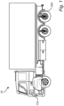
- a vehicle 10 in the form of a truck.
- the vehicle comprises a traction motor (not shown) for propelling the wheels of the vehicle.
- the traction motor is in the example embodiment an electric traction motor in the form of an electric machine.
- the vehicle 10 also comprises a control unit 116 for controlling various operations as will also be described in further detail below, and a vehicle air management system (not shown in detail in Fig. 1 ) operable to control the supply of pressurized air to various air consumers of the vehicle.
- Fig. 1 is illustrating an exemplified air consumer 200 in the form of an air suspension system.
- the control unit 116 may include a microprocessor, microcontroller, programmable digital signal processor or another programmable device.
- the control unit may also, or instead, include an application specific integrated circuit, a programmable gate array or programmable array logic, a programmable logic device, or a digital signal processor.
- the control unit 116 includes a programmable device such as the microprocessor, microcontroller or programmable digital signal processor mentioned above, the processor may further include computer executable code that controls operation of the programmable device.
- the air management system 100 comprises an air inlet 202 which is arranged to receive ambient air.
- the ambient air is directed from the air inlet 202 to an air compressor 102 via an air inlet conduit 204.
- the air management system 100 further comprises an air tank 104 arranged in downstream fluid communication with the air compressor 102.
- the air tank 104 is configured to receive pressurized air from the air compressor 102 via an air tank inlet conduit 206.
- the pressurized air is entering the air tank 104 at a tank inlet 208.
- the air tank 104 is configured to controllably supply the pressurized air to the air consumer 200 of the vehicle 10 when the air consumer requests a flow of pressurized air.
- the air consumer 200 is arranged in fluid communication with the air tank 104 by means of a first outlet conduit 210.
- the first outlet conduit 210 is arranged between a first outlet 106 or the air tank 104 and an inlet 212 of the air consumer 200.
- Fig. 2 illustrates a single air consumer 200, it should be readily understood that the present invention is particularly applicable for the use of a plurality of air consumers but only one air consumer is illustrated for simplified understanding.
- the air consumer may also comprise an outlet. Such outlet can direct the air, after usage, to the ambient environment, or back to the air inlet 202. The outlet can direct the consumed air to other positions as well, such as to another air consumer of the vehicle, etc.
- the vehicle air management system 100 also comprises a boost air tank 108.
- the boost air tank 108 is arranged in downstream fluid communication with the air tank 104.
- the boost air tank 108 is connected to the air tank 104 via a second outlet conduit 214.
- the second outlet conduit 214 is connected between a second outlet 110 of the air tank 104 and a boost tank inlet 216.
- the boost air tank 108 is also arranged in upstream fluid communication with the air compressor 102.
- a boost outlet conduit 218 is connected between a boost outlet 222 and the air compressor 102.
- the boost outlet conduit 218 is connected to an intersection position 220, which intersection position 220 connects to the boost outlet conduit 218 to the air inlet conduit 204.
- pressurized air from the boost air tank 108 can, as will be described in further detail below, be supplied to the air compressor 102.
- the vehicle air management system 100 comprises a first valve112 and a second valve 114.
- the first valve 112 is arranged in downstream fluid communication with the second outlet 110 of the air tank 104.
- the first valve 112 is arranged in the second outlet conduit 214, i.e. in fluid communication between the air tank 104 and the boost air tank 108.
- the second valve 114 is arranged in downstream fluid communication with the boost air tank 108.
- the second valve 114 is arranged in the boost outlet conduit 218, i.e. in fluid communication between the boost air tank 108 and the air compressor 102.
- the first valve 112 is preferably arranged as a normally open valve. Hence, the first valve 112 is arranged in an open position when not actively controlled, thereby allowing a flow of air from the air tank 104 to be supplied to the boost air tank 108. The first valve 112 is arranged to prevent air from the air tank 104 to reach the boost air tank 108 when being actively controlled by the control unit 116 to assume a closed position.
- the second valve 114 on the other hand is preferably arranged as a normally closed valve. Hence the second valve 114 is arranged in a closed position when not actively controlled, thereby preventing a flow of pressurized air from the boost air tank to reach the air compressor 102. The second valve 114 is arranged to allow a flow of pressurized air from the boost air tank 108 to reach the air compressor 102 when being actively controlled by the control unit 116 to assume an open position.
- control unit 116 is, as can be seen in Fig. 2 , is thus connected to the first 112 and second valves 114 to control operation thereof.
- the control unit 116 may be connected to the first 112 and second 114 valves by wire or by wireless communication.
- the control unit 116 is configured to receive a signal indicative of an air consumption level of the air consumer 200.
- the signal may be received from e.g. an air tank pressure sensor which is described in further detail below.
- the control unit 116 may also receive a signal indicating the current usage of the air consumer 200.
- Such signal may, for example, be received by an upper layer vehicle control system which determines the current operation of the air consumer.
- the air consumption level is a measure of how much air being needed by the air consumer for proper operation.
- the control unit 116 compares the air consumption level with a predetermined threshold limit.
- the predetermined threshold limit preferably corresponds to the amount of pressurized air being suppliable from the air tank 104 through the first outlet 106. More preferably, the predetermined threshold limit is a value indicating the rate of pressurized air that can be supplied through the first outlet 106, i.e. how much air, per unit of time, the air tank 104 is able to deliver to the air consumer 200.
- the control unit 116 controls the first valve 112 to assume the closed position as well as controls the second valve 114 to assume the open position.
- the control unit 116 controls the first valve 112 to assume the closed position as well as controls the second valve 114 to assume the open position when the air tank 104 is unable to meet the air pressure demand from the air consumer 200.
- the first 112 and second 114 valves are controlled to assume the respective closed and open positions at substantially the same point in time.
- the boost air tank 108 is supercharging the air compressor 102 with pressurized air, thereby enabling the air compressor 102 to deliver a flow of increased pressurized air to the air tank 104.
- the flow of increased pressurized air is thus provided with a higher pressure and air mass flow level compared to the pressure and air mass flow level obtainable by the air compressor 102 when the second valve 114 is closed. Since the first valve 112 is closed, air pressure can be steadily increased in the air tank 104 to meet the air pressure demand from the air consumer.
- the control unit controls the first valve 112 to assume the open position, and controls the second valve 114 to assume the closed position.
- air is allowed to be supplied from the air tank 104 to the boost air tank 108, while pressurized air from the boost air tank 108 is prevented from reaching the air compressor 102.
- the air pressure level can thus be increased in the boost air tank 108 for a subsequent supercharging of the air compressor 102.
- the control unit 116 controls the first valve 112 to assume the open position by omitting the transmittal of a control signal to the first valve 112.
- the control unit 116 controls the second valve 114 to assume the closed position by omitting the transmittal of a control signal to the second valve 114.
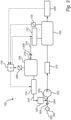
- Fig. 3 is a schematic illustration of a vehicle air management system according to another example embodiment.
- the components, and their functionality, of the vehicle air management system 100 described above in relation to Fig. 2 are also present in the Fig. 3 example embodiment. These components will therefore not be described in detail in the following disclosure.
- the air tank 104 is provided with an air tank pressure sensor 118 connected to the control unit 116.
- the air tank pressure sensor 118 can hereby detect sudden variations in the pressure level of the air tank.
- the control unit 116 can determine, based on the signal from the air tank pressure sensor 118, a reduction rate of the air pressure within the air tank 104 to thereby determine an air consumption level of the air consumer 200.
- the vehicle air management system 100 may hereby be determined to be unable to meet the air pressure demand from the air consumer if the reduction rate of air pressure within the air tank 104 exceeds a production rate of pressurized air from the air compressor 102.
- the air compressor 102 should be supercharged with pressurized air from the boost air tank 108 according to the above description.
- the air consumer 200 itself may be connected to the control unit 116, whereby the control unit 116 can receive a signal indicating the current air usage of the air consumer 200 for determining the above described air consumption level.
- the vehicle air management system 100 depicted in Fig. 3 also comprises an air filter 302 and a first one-way valve 304 in the inlet conduit 204.
- the air filter 302 and the first one-way valve 304 are arranged in fluid communication between the air inlet 202 and the air compressor 102.
- the vehicle air management system 100 also comprises a second one-way valve 306 positioned in the second outlet conduit 214, i.e. in fluid communication between the first valve 112 and the boost tank inlet 216.
- the vehicle air management system 100 further comprises a pressure regulator 120 in the boost outlet conduit 218.
- the pressure regulator 120 which is preferably a variable pressure regulator, is arranged in fluid communication between the second valve 114 and the intersection position 220, i.e. arranged upstream the air compressor 102.
- the pressure regulator 120 may be controlled by the control unit 116.
- the control unit 116 can control the variable pressure regulator to deliver a flow of pressurized air, with a suitable pressure level for meeting the pressure demand, to the air compressor 102.
- the boost air tank in Fig. 3 further comprises boost air tank pressure sensor 308 connected to the control unit 116.
- the control unit 116 can hereby receive a signal indicative of the pressure level of the boost air tank 108 and control the first 112 and second 114 valves based on the signal. For example, when the pressure level in the boost air tank is below a predetermined boost air pressure threshold limit, the first valve can be kept open, and the second valve kept closed to increase the pressure level in the boost air tank 108. However, should the pressure level in the boost air tank 108 exceed the predetermined boost air pressure threshold limit, the control unit 116 may control the first valve 112 to assume the closed position and control the second valve 114 to assume the open position to thereby reduce the pressure level in the boost air tank 108.
- the vehicle air management system 100 further comprises an air dryer in fluid communication between the air compressor 102 and the air tank 104 for removing liquid fluid from the pressurized air entering the air tank 104.
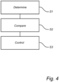
- Fig. 4 is a flow chart of a method of controlling the vehicle air management system 100 described above in relation to Figs. 2 and 3 .
- the control unit 116 determines S1 an air consumption level of the air consumer 200. This can be accomplished according to the above description, i.e. by receiving a signal from the air tank pressure sensor 118, receiving a signal directly from the air consumer 200 relating to the current consumption, etc.
- the control unit thereafter compares S2 the air consumption level with a predetermined threshold limit.
- the control unit 116 controls S3 the first valve 112 to assume the closed position to prevent air from the air tank 104 to reach the boost air tank 108, and controls the second valve 114 to assume the open position to allow pressurized air from the boost air tank 108 to reach air compressor 102.
Landscapes
- Engineering & Computer Science (AREA)
- Mechanical Engineering (AREA)
- Physics & Mathematics (AREA)
- General Engineering & Computer Science (AREA)
- Fluid Mechanics (AREA)
- Transportation (AREA)
- General Physics & Mathematics (AREA)
- Automation & Control Theory (AREA)
- Valves And Accessory Devices For Braking Systems (AREA)
Claims (15)
- Fahrzeugluftsteuerungssystem (100) für ein Fahrzeug (10), das Fahrzeugluftsteuerungssystem umfassend:- einen Luftkompressor (102), der konfiguriert ist, um Luft von einem Lufteinlass über eine Lufteinlassleitung des Fahrzeugluftsteuerungssystems zu erhalten,- einen Lufttank (104), der in nachgeschalteter Fluidverbindung mit dem Luftkompressor (102) angeordnet und konfiguriert ist, um Druckluft von dem Luftkompressor (102) zu erhalten, wobei der Lufttank (104) einen ersten Auslass (106) umfasst, der mit mindestens einem Luftverbraucher (200) des Fahrzeugs verbindbar ist,- einen Zusatzlufttank (108), der konfiguriert ist, um Druckluft zu enthalten, wobei der Zusatzlufttank (108) in nachgeschalteter Fluidverbindung mit einem zweiten Auslass (110) des Lufttanks (104) angeordnet ist, wobei der Zusatzlufttank (108) in vorgeschalteter Fluidverbindung mit dem Luftkompressor (102) angeordnet ist,- ein erstes Ventil (112), das in Fluidverbindung zwischen dem Lufttank (104) und dem Zusatzlufttank (108) angeordnet ist, dadurch gekennzeichnet, dass- ein zweites Ventil (114), das in Fluidverbindung zwischen dem Zusatzlufttank (108) und dem Luftkompressor (102) angeordnet ist, und- eine Steuereinheit (116), die mit dem ersten (112) und dem zweiten (114) Ventil verbunden ist, wobei die Steuereinheit eine Steuerschaltung umfasst, die konfiguriert ist um:- ein Signal zu empfangen, das ein Luftverbrauchsniveau des mindestens einen Luftverbrauchers angibt,- das Luftverbrauchsniveau mit einem vorbestimmten Schwellenwert zu vergleichen, und wenn das Luftverbrauchsniveau über dem vorbestimmten Schwellenwert liegt:- das erste Ventil so zu steuern, dass es eine geschlossene Position einnimmt, um zu verhindern, dass Luft aus dem Lufttank in den Zusatzlufttank gelangt, und das zweite Ventil so zu steuern, dass es eine offene Position einnimmt, um zu ermöglichen, dass Druckluft aus dem Zusatzlufttank in den Luftkompressor gelangt, um eine Produktionsrate der vom Luftkompressor gelieferten Druckluft zu erhöhen.
- Fahrzeugluftsteuerungssystem (100) nach Anspruch 1, wobei der Lufttank ferner einen Lufttankdrucksensor (118) umfasst, der mit der Steuereinheit (116) verbunden ist, wobei das Luftverbrauchsniveau anzeigende Signal so konfiguriert ist, dass es von dem Lufttankdrucksensor empfangen wird.
- Fahrzeugluftsteuerungssystem (100) nach Anspruch 2, wobei das Luftverbrauchsniveau auf einer Reduktionsrate des Luftdrucks im Lufttank (104) basiert.
- Fahrzeugluftsteuerungssystem (100) nach Anspruch 3, wobei die vorbestimmte Schwellenwertgrenze auf einer Produktionsrate von Druckluft basiert, die vom Luftkompressor zum Lufttank geliefert wird.
- Fahrzeugluftsteuerungssystem (100) nach einem der vorhergehenden Ansprüche, wobei das Fahrzeugluftsteuerungssystem ferner einen Druckregler (120) in Fluidverbindung zwischen dem zweiten Ventil (114) und dem Luftkompressor (102) umfasst.
- Fahrzeugluftsteuerungssystem (100) nach Anspruch 5, wobei der Druckregler (120) ein variabler Druckregler ist.
- Fahrzeugluftsteuerungssystem (100) nach einem der vorhergehenden Ansprüche, wobei das erste Ventil (112) ein normalerweise offenes Ventil ist.
- Fahrzeugluftsteuerungssystem (100) nach einem der vorhergehenden Ansprüche, wobei das zweite Ventil (114) ein normalerweise geschlossenes Ventil ist.
- Fahrzeugluftsteuerungssystem (100) nach einem der vorhergehenden Ansprüche, wobei die Steuerschaltung ferner konfiguriert ist, um, wenn das Luftverbrauchsniveau unter dem vorbestimmten Schwellenwert liegt, das erste Ventil so zu steuern, dass es eine offene Position einnimmt, um die Zufuhr von Luft aus dem Lufttank zum Zusatzlufttank zu ermöglichen, und das zweite Ventil so zu steuern, dass es eine geschlossene Position einnimmt, um zu verhindern, dass Druckluft aus dem Zusatzlufttank den Luftkompressor erreicht.
- Fahrzeugluftsteuerungssystem (100) nach Anspruch 9, in Abhängigkeit von den Ansprüchen 7 und 8, wobei die Steuerschaltung konfiguriert ist, um das erste Ventil so zu steuern, dass es die offene Position einnimmt, und das zweite Ventil so, dass es die geschlossene Position einnimmt, indem ein Steuersignal an das erste bzw. zweite Ventil nicht übertragen wird.
- Fahrzeugluftsteuerungssystem (100) nach einem der vorhergehenden Ansprüche, wobei der Zusatzlufttank einen Zusatzlufttankdrucksensor umfasst, der mit der Steuereinheit verbunden ist, wobei die Steuerschaltung konfiguriert ist, um das erste und das zweite Ventil auf der Grundlage eines Signals zu steuern, das von dem Ladelufttankdrucksensor empfangen wird, wobei das Signal ein Druckniveau der Luft in dem Zusatzlufttank anzeigt.
- Fahrzeug, umfassend ein Fahrzeugluftsteuerungssystem (100) nach einem der vorhergehenden Ansprüche und einen Luftverbraucher, der in nachgeschalteter Fluidverbindung mit dem ersten Auslass des Lufttanks angeordnet ist.
- Verfahren zum Steuern eines Fahrzeugluftsteuerungssystems, das Luftsteuerungssystem umfassend einen Luftkompressor, einen Lufttank, der in nachgeschalteter Fluidverbindung mit dem Luftkompressor angeordnet und konfiguriert ist, um Druckluft von dem Luftkompressor zu erhalten, wobei der Lufttank einen ersten Auslass umfasst, der mit einem Luftverbraucher des Fahrzeugs verbunden ist, und einen Zusatzlufttank, der konfiguriert ist, um Druckluft zu enthalten, wobei der Zusatzlufttank in nachgeschalteter Fluidverbindung mit einem zweiten Auslass des Lufttanks angeordnet ist, wobei der Zusatzlufttank in vorgeschalteter Fluidverbindung mit dem Luftkompressor angeordnet ist, ein erstes Ventil, das in Fluidverbindung zwischen dem Lufttank und dem Zusatzlufttank angeordnet ist, dadurch gekennzeichnet, dass ein zweites Ventil in Fluidverbindung zwischen dem Zusatzlufttank und dem Luftkompressor angeordnet ist, wobei das Verfahren umfasst:- Bestimmen (S1) eines Luftverbrauchsniveaus des Luftverbrauchers,- Vergleichen (S2) des Luftverbrauchsniveaus mit einem vorbestimmten Schwellenwert, und wenn das Luftverbrauchsniveau über dem vorbestimmten Schwellenwert liegt:- Steuern des ersten Ventils (S3), dass es eine geschlossene Position einnimmt, um zu verhindern, dass Luft aus dem Lufttank in den Zusatzlufttank gelangt, und Steuern des zweiten Ventils, dass es eine offene Position einnimmt, um zu ermöglichen, dass Druckluft aus dem Zusatzlufttank in den Luftkompressor gelangt, um eine Produktionsrate der vom Luftkompressor gelieferten Druckluft zu erhöhen.
- Fahrzeugluftsteuerungssystem nach Anspruch 1, ferner umfassend ein Computerprogramm mit Programmcodemitteln zur Durchführung der Schritte nach Anspruch 13, wenn das Programm auf einem Computer ausgeführt wird.
- Fahrzeugluftsteuerungssystem nach Anspruch 1, ferner umfassend ein computerlesbares Medium mit einem Computerprogramm, das Programmmittel zum Durchführen der Schritte nach Anspruch 13 umfasst, wenn das Programmmittel auf einem Computer ausgeführt wird.
Priority Applications (2)
| Application Number | Priority Date | Filing Date | Title |
|---|---|---|---|
| EP21214836.5A EP4197828B1 (de) | 2021-12-15 | 2021-12-15 | Fahrzeugluftsteuerungssystem und verfahren zum steuern eines fahrzeugluftsteuerungssystem |
| US18/064,049 US12252085B2 (en) | 2021-12-15 | 2022-12-09 | Vehicle air management system |
Applications Claiming Priority (1)
| Application Number | Priority Date | Filing Date | Title |
|---|---|---|---|
| EP21214836.5A EP4197828B1 (de) | 2021-12-15 | 2021-12-15 | Fahrzeugluftsteuerungssystem und verfahren zum steuern eines fahrzeugluftsteuerungssystem |
Publications (3)
| Publication Number | Publication Date |
|---|---|
| EP4197828A1 EP4197828A1 (de) | 2023-06-21 |
| EP4197828C0 EP4197828C0 (de) | 2024-08-28 |
| EP4197828B1 true EP4197828B1 (de) | 2024-08-28 |
Family
ID=79024384
Family Applications (1)
| Application Number | Title | Priority Date | Filing Date |
|---|---|---|---|
| EP21214836.5A Active EP4197828B1 (de) | 2021-12-15 | 2021-12-15 | Fahrzeugluftsteuerungssystem und verfahren zum steuern eines fahrzeugluftsteuerungssystem |
Country Status (2)
| Country | Link |
|---|---|
| US (1) | US12252085B2 (de) |
| EP (1) | EP4197828B1 (de) |
Families Citing this family (1)
| Publication number | Priority date | Publication date | Assignee | Title |
|---|---|---|---|---|
| DE102024200098B3 (de) * | 2024-01-05 | 2024-10-24 | Continental Automotive Technologies GmbH | Luftfederungsanlage eines Kraftfahrzeugs und Verfahren zum Betreiben einer Luftfederungsanlage |
Family Cites Families (33)
| Publication number | Priority date | Publication date | Assignee | Title |
|---|---|---|---|---|
| JP2631491B2 (ja) * | 1988-02-29 | 1997-07-16 | カヤバ工業株式会社 | エアサスペンション制御装置 |
| DE19515895A1 (de) * | 1995-04-29 | 1996-10-31 | Bosch Gmbh Robert | Druckluft-Versorgungseinrichtung für Fahrzeug-Druckluftanlagen sowie Verfahren zum Steuern der Druckluft-Versorgungseinrichtung |
| SE507378C3 (sv) * | 1996-09-02 | 1998-06-29 | Volvo Lastvagnar Ab | Tryckluftsystem foer lastfordon |
| US6318813B1 (en) * | 2000-01-20 | 2001-11-20 | Honeywell Commercial Vehicle Systems Co. | Air spring reservoir emergency brake backup system |
| JP3668421B2 (ja) | 2000-11-01 | 2005-07-06 | Smc株式会社 | 空気圧縮装置 |
| US6601625B2 (en) * | 2000-11-22 | 2003-08-05 | Richard M. Rheinhardt | Wheel with integral compressed air tank apparatus |
| EP1651492B1 (de) * | 2003-07-28 | 2008-03-05 | WABCO GmbH | Elektronische druckluftanlage |
| SE527303C2 (sv) * | 2004-06-30 | 2006-02-07 | Volvo Lastvagnar Ab | Arrangemang och förfarande vid tryckluftssystem |
| DE102006023606A1 (de) * | 2006-05-19 | 2007-11-22 | Knorr-Bremse Systeme für Nutzfahrzeuge GmbH | Druckluftversorgungseinrichtung für ein Nutzfahrzeug |
| DE102008004807B4 (de) * | 2007-02-07 | 2012-10-31 | Knorr-Bremse Systeme für Nutzfahrzeuge GmbH | Druckluftversorgungsanlage und Verfahren zum Betreiben einer Druckluftversorgungsanlage |
| JP2009002432A (ja) * | 2007-06-21 | 2009-01-08 | Yamaha Motor Co Ltd | ガス残量算出装置 |
| FR2921127B1 (fr) * | 2007-09-14 | 2010-03-12 | Peugeot Citroen Automobiles Sa | Dispositif de commande pneumatique de vehicule automobile |
| US8418463B2 (en) * | 2010-04-15 | 2013-04-16 | Ford Global Technologies, Llc | Condensate management for motor-vehicle compressed air storage systems |
| EP2715093A2 (de) * | 2011-05-23 | 2014-04-09 | Storewatt | Vorrichtung zur lagerung und ausgabe von flüssigkeiten und verfahren zur lagerung und ausgabe eines komprimierten gases in einer solchen vorrichtung |
| US9802593B2 (en) * | 2011-06-07 | 2017-10-31 | Bendix Commercial Vehicle Systems Llc | Multi-pressure valve controller and method for a vehicle braking system |
| JP6268001B2 (ja) * | 2014-03-11 | 2018-01-24 | 日野自動車株式会社 | 車両用エア供給システム |
| JP6510876B2 (ja) * | 2015-05-01 | 2019-05-08 | 株式会社神戸製鋼所 | 圧縮空気貯蔵発電方法および圧縮空気貯蔵発電装置 |
| DE102016100526A1 (de) * | 2016-01-14 | 2017-07-20 | Knorr-Bremse Systeme für Nutzfahrzeuge GmbH | Steuervorrichtung zum Steuern einer Bremsanlage für ein Fahrzeug, Bremsanlage für ein Fahrzeug, Verfahren zum Betreiben einer Steuervorrichtung und Verfahren zum Beaufschlagen zumindest einer Bremseinrichtung einer Bremsanlage für ein Fahrzeug mit einem Bremsdruck |
| US20180100362A1 (en) * | 2016-10-12 | 2018-04-12 | Caterpillar Global Mining Equipment Llc | Electronically-Controlled Compressed Air System |
| EP3577385B1 (de) * | 2017-02-01 | 2025-02-26 | Hydrostor Inc. | Hydrostatisch kompensiertes druckgasenergiespeichersystem |
| US10596873B2 (en) * | 2017-02-09 | 2020-03-24 | Beijingwest Industries Co., Ltd. | Vehicle suspension control system and method of operation thereof |
| JP7009621B2 (ja) * | 2017-06-16 | 2022-01-25 | ベース エア マネジメント リミテッド | 空気管理システム、車両の安定性を制御する方法、車両サスペンションシステム |
| US10220665B2 (en) * | 2017-06-16 | 2019-03-05 | BASE Air Management, Inc. | Symmetrically dynamic equalized volume and pressure air management system |
| GB201717040D0 (en) * | 2017-10-17 | 2017-11-29 | Innovatium Llp | Compressed air storage |
| DE102017011526A1 (de) * | 2017-12-13 | 2019-06-13 | Wabco Gmbh | Druckluftversorgungsanlage zum Betreiben einer Pneumatikanlage, Verfahren und Fahrzeug |
| CN111971190A (zh) * | 2018-02-05 | 2020-11-20 | 基航管理有限公司 | 用于空气管理系统的控制单元 |
| DE102018102764A1 (de) * | 2018-02-07 | 2019-08-08 | Haldex Brake Products Aktiebolag | Bremsanlage für ein Nutzfahrzeug, Druckluftaufbereitungseinheit und Verwendung einer Druckluftaufbereitungseinheit |
| US12297056B2 (en) * | 2018-05-17 | 2025-05-13 | Hydrostor Inc. | Construction elements and maintenance methods for compressed air energy storage systems |
| DE102018217975A1 (de) * | 2018-10-22 | 2020-04-23 | Zf Friedrichshafen Ag | Druckluftanlage sowie Verfahren zur Speicherung von Abluft mit der Druckluftanlage |
| EP3921572A4 (de) * | 2019-02-08 | 2022-12-07 | Hydrostor Inc. | Druckgasenergiespeichersystem |
| CN111002962B (zh) * | 2019-12-04 | 2021-03-02 | 珠海格力电器股份有限公司 | 一种汽车控制方法、装置、计算机可读存储介质及汽车 |
| WO2021250666A1 (en) * | 2020-06-09 | 2021-12-16 | Storage Drop Ltd | Hydraulic compressed air energy storage system |
| US11572830B2 (en) * | 2021-02-19 | 2023-02-07 | Ford Global Technologies, Llc | Method and system for on vehicle compressed air generation |
-
2021
- 2021-12-15 EP EP21214836.5A patent/EP4197828B1/de active Active
-
2022
- 2022-12-09 US US18/064,049 patent/US12252085B2/en active Active
Also Published As
| Publication number | Publication date |
|---|---|
| EP4197828C0 (de) | 2024-08-28 |
| US20230182664A1 (en) | 2023-06-15 |
| US12252085B2 (en) | 2025-03-18 |
| EP4197828A1 (de) | 2023-06-21 |
Similar Documents
| Publication | Publication Date | Title |
|---|---|---|
| US6845988B2 (en) | Method of controlling the quantity of air in a vehicle level control system | |
| US8260494B2 (en) | Method and apparatus to optimize energy efficiency of air compressor in vehicle air brake application | |
| US9650029B2 (en) | Compressed air supply system and method for operating a compressed air supply system | |
| JP3716215B2 (ja) | 車両用電子制御式ブレーキシステム | |
| EP1529704B1 (de) | Verfahren und Vorrichtung zur Regelung der Trocknung und Regenerierung einer Lufttrocknungseinheit in einem pneumatisch-hydraulischen Bremssystem eines Fahrzeuges | |
| US8290674B2 (en) | Brake control system and brake control method | |
| KR20080003770A (ko) | 공압식 레벨 제어 시스템을 구비한 차량 | |
| EP4197828B1 (de) | Fahrzeugluftsteuerungssystem und verfahren zum steuern eines fahrzeugluftsteuerungssystem | |
| EP3844393B1 (de) | Doppelluftverdichter für hybridfahrzeuge | |
| US20100147271A1 (en) | Compressed Air System | |
| US9180854B2 (en) | Dual purpose dryers for high flow | |
| WO1998007588A1 (en) | Device and method for control of air compressor | |
| US7765043B2 (en) | Power supply control apparatus and method | |
| CN100383379C (zh) | 电源控制装置及方法 | |
| CN100389034C (zh) | 电子压缩空气系统 | |
| CN108999962A (zh) | 用于在自动变速器蓄能器内存储动能的方法和设备 | |
| MX2007006700A (es) | Control electronico para el sistema de carga de aire comprimido de un tractocamión deservicio pesado. | |
| CN116811824A (zh) | 车用干燥器再生控制系统及其再生控制方法 | |
| EP4163167B1 (de) | Nutzfahrzeug mit einem pneumatischen system und verfahren zur steuerung eines pneumatischen systems | |
| CN115723728A (zh) | 商用车辆的制动力补充装置及方法 | |
| SE541399C2 (en) | A method and system for controlling air supply | |
| EP4400718A1 (de) | Steuerung eines elektrischen luftkompressors | |
| KR20020039427A (ko) | 차량 섀시의 윤활유 공급장치 | |
| CN120792381A (zh) | 电动货车胎压的动态调整方法、系统及电子设备 | |
| CN119872156A (zh) | 空气悬架气路系统及其控制方法、控制装置和车辆 |
Legal Events
| Date | Code | Title | Description |
|---|---|---|---|
| PUAI | Public reference made under article 153(3) epc to a published international application that has entered the european phase |
Free format text: ORIGINAL CODE: 0009012 |
|
| STAA | Information on the status of an ep patent application or granted ep patent |
Free format text: STATUS: THE APPLICATION HAS BEEN PUBLISHED |
|
| AK | Designated contracting states |
Kind code of ref document: A1 Designated state(s): AL AT BE BG CH CY CZ DE DK EE ES FI FR GB GR HR HU IE IS IT LI LT LU LV MC MK MT NL NO PL PT RO RS SE SI SK SM TR |
|
| STAA | Information on the status of an ep patent application or granted ep patent |
Free format text: STATUS: REQUEST FOR EXAMINATION WAS MADE |
|
| 17P | Request for examination filed |
Effective date: 20231205 |
|
| RBV | Designated contracting states (corrected) |
Designated state(s): AL AT BE BG CH CY CZ DE DK EE ES FI FR GB GR HR HU IE IS IT LI LT LU LV MC MK MT NL NO PL PT RO RS SE SI SK SM TR |
|
| GRAP | Despatch of communication of intention to grant a patent |
Free format text: ORIGINAL CODE: EPIDOSNIGR1 |
|
| STAA | Information on the status of an ep patent application or granted ep patent |
Free format text: STATUS: GRANT OF PATENT IS INTENDED |
|
| INTG | Intention to grant announced |
Effective date: 20240325 |
|
| GRAS | Grant fee paid |
Free format text: ORIGINAL CODE: EPIDOSNIGR3 |
|
| GRAA | (expected) grant |
Free format text: ORIGINAL CODE: 0009210 |
|
| STAA | Information on the status of an ep patent application or granted ep patent |
Free format text: STATUS: THE PATENT HAS BEEN GRANTED |
|
| AK | Designated contracting states |
Kind code of ref document: B1 Designated state(s): AL AT BE BG CH CY CZ DE DK EE ES FI FR GB GR HR HU IE IS IT LI LT LU LV MC MK MT NL NO PL PT RO RS SE SI SK SM TR |
|
| REG | Reference to a national code |
Ref country code: CH Ref legal event code: EP |
|
| REG | Reference to a national code |
Ref country code: DE Ref legal event code: R096 Ref document number: 602021017878 Country of ref document: DE |
|
| REG | Reference to a national code |
Ref country code: IE Ref legal event code: FG4D |
|
| U01 | Request for unitary effect filed |
Effective date: 20240924 |
|
| U07 | Unitary effect registered |
Designated state(s): AT BE BG DE DK EE FI FR IT LT LU LV MT NL PT RO SE SI Effective date: 20241016 |
|
| PG25 | Lapsed in a contracting state [announced via postgrant information from national office to epo] |
Ref country code: NO Free format text: LAPSE BECAUSE OF FAILURE TO SUBMIT A TRANSLATION OF THE DESCRIPTION OR TO PAY THE FEE WITHIN THE PRESCRIBED TIME-LIMIT Effective date: 20241128 |
|
| PG25 | Lapsed in a contracting state [announced via postgrant information from national office to epo] |
Ref country code: GR Free format text: LAPSE BECAUSE OF FAILURE TO SUBMIT A TRANSLATION OF THE DESCRIPTION OR TO PAY THE FEE WITHIN THE PRESCRIBED TIME-LIMIT Effective date: 20241129 Ref country code: PL Free format text: LAPSE BECAUSE OF FAILURE TO SUBMIT A TRANSLATION OF THE DESCRIPTION OR TO PAY THE FEE WITHIN THE PRESCRIBED TIME-LIMIT Effective date: 20240828 |
|
| PG25 | Lapsed in a contracting state [announced via postgrant information from national office to epo] |
Ref country code: IS Free format text: LAPSE BECAUSE OF FAILURE TO SUBMIT A TRANSLATION OF THE DESCRIPTION OR TO PAY THE FEE WITHIN THE PRESCRIBED TIME-LIMIT Effective date: 20241228 |
|
| PG25 | Lapsed in a contracting state [announced via postgrant information from national office to epo] |
Ref country code: HR Free format text: LAPSE BECAUSE OF FAILURE TO SUBMIT A TRANSLATION OF THE DESCRIPTION OR TO PAY THE FEE WITHIN THE PRESCRIBED TIME-LIMIT Effective date: 20240828 |
|
| PG25 | Lapsed in a contracting state [announced via postgrant information from national office to epo] |
Ref country code: ES Free format text: LAPSE BECAUSE OF FAILURE TO SUBMIT A TRANSLATION OF THE DESCRIPTION OR TO PAY THE FEE WITHIN THE PRESCRIBED TIME-LIMIT Effective date: 20240828 Ref country code: RS Free format text: LAPSE BECAUSE OF FAILURE TO SUBMIT A TRANSLATION OF THE DESCRIPTION OR TO PAY THE FEE WITHIN THE PRESCRIBED TIME-LIMIT Effective date: 20241128 |
|
| U20 | Renewal fee for the european patent with unitary effect paid |
Year of fee payment: 4 Effective date: 20241225 |
|
| PG25 | Lapsed in a contracting state [announced via postgrant information from national office to epo] |
Ref country code: RS Free format text: LAPSE BECAUSE OF FAILURE TO SUBMIT A TRANSLATION OF THE DESCRIPTION OR TO PAY THE FEE WITHIN THE PRESCRIBED TIME-LIMIT Effective date: 20241128 Ref country code: PL Free format text: LAPSE BECAUSE OF FAILURE TO SUBMIT A TRANSLATION OF THE DESCRIPTION OR TO PAY THE FEE WITHIN THE PRESCRIBED TIME-LIMIT Effective date: 20240828 Ref country code: NO Free format text: LAPSE BECAUSE OF FAILURE TO SUBMIT A TRANSLATION OF THE DESCRIPTION OR TO PAY THE FEE WITHIN THE PRESCRIBED TIME-LIMIT Effective date: 20241128 Ref country code: IS Free format text: LAPSE BECAUSE OF FAILURE TO SUBMIT A TRANSLATION OF THE DESCRIPTION OR TO PAY THE FEE WITHIN THE PRESCRIBED TIME-LIMIT Effective date: 20241228 Ref country code: HR Free format text: LAPSE BECAUSE OF FAILURE TO SUBMIT A TRANSLATION OF THE DESCRIPTION OR TO PAY THE FEE WITHIN THE PRESCRIBED TIME-LIMIT Effective date: 20240828 Ref country code: GR Free format text: LAPSE BECAUSE OF FAILURE TO SUBMIT A TRANSLATION OF THE DESCRIPTION OR TO PAY THE FEE WITHIN THE PRESCRIBED TIME-LIMIT Effective date: 20241129 Ref country code: ES Free format text: LAPSE BECAUSE OF FAILURE TO SUBMIT A TRANSLATION OF THE DESCRIPTION OR TO PAY THE FEE WITHIN THE PRESCRIBED TIME-LIMIT Effective date: 20240828 |
|
| PG25 | Lapsed in a contracting state [announced via postgrant information from national office to epo] |
Ref country code: SM Free format text: LAPSE BECAUSE OF FAILURE TO SUBMIT A TRANSLATION OF THE DESCRIPTION OR TO PAY THE FEE WITHIN THE PRESCRIBED TIME-LIMIT Effective date: 20240828 |
|
| PG25 | Lapsed in a contracting state [announced via postgrant information from national office to epo] |
Ref country code: CZ Free format text: LAPSE BECAUSE OF FAILURE TO SUBMIT A TRANSLATION OF THE DESCRIPTION OR TO PAY THE FEE WITHIN THE PRESCRIBED TIME-LIMIT Effective date: 20240828 |
|
| PG25 | Lapsed in a contracting state [announced via postgrant information from national office to epo] |
Ref country code: SK Free format text: LAPSE BECAUSE OF FAILURE TO SUBMIT A TRANSLATION OF THE DESCRIPTION OR TO PAY THE FEE WITHIN THE PRESCRIBED TIME-LIMIT Effective date: 20240828 |
|
| PLBE | No opposition filed within time limit |
Free format text: ORIGINAL CODE: 0009261 |
|
| STAA | Information on the status of an ep patent application or granted ep patent |
Free format text: STATUS: NO OPPOSITION FILED WITHIN TIME LIMIT |
|
| PG25 | Lapsed in a contracting state [announced via postgrant information from national office to epo] |
Ref country code: MC Free format text: LAPSE BECAUSE OF FAILURE TO SUBMIT A TRANSLATION OF THE DESCRIPTION OR TO PAY THE FEE WITHIN THE PRESCRIBED TIME-LIMIT Effective date: 20240828 |
|
| REG | Reference to a national code |
Ref country code: CH Ref legal event code: PL |
|
| 26N | No opposition filed |
Effective date: 20250530 |
|
| PG25 | Lapsed in a contracting state [announced via postgrant information from national office to epo] |
Ref country code: CH Free format text: LAPSE BECAUSE OF NON-PAYMENT OF DUE FEES Effective date: 20241231 |
|
| PG25 | Lapsed in a contracting state [announced via postgrant information from national office to epo] |
Ref country code: IE Free format text: LAPSE BECAUSE OF NON-PAYMENT OF DUE FEES Effective date: 20241215 |