EP4197747B1 - Connection part for an industrial assembly process, part connection and method for adhesively connecting a connection part and a mating part - Google Patents
Connection part for an industrial assembly process, part connection and method for adhesively connecting a connection part and a mating part Download PDFInfo
- Publication number
- EP4197747B1 EP4197747B1 EP21214723.5A EP21214723A EP4197747B1 EP 4197747 B1 EP4197747 B1 EP 4197747B1 EP 21214723 A EP21214723 A EP 21214723A EP 4197747 B1 EP4197747 B1 EP 4197747B1
- Authority
- EP
- European Patent Office
- Prior art keywords
- connection
- connection surface
- body portion
- positioning protrusion
- securing
- Prior art date
- Legal status (The legal status is an assumption and is not a legal conclusion. Google has not performed a legal analysis and makes no representation as to the accuracy of the status listed.)
- Active
Links
- 230000013011 mating Effects 0.000 title claims description 68
- 238000000034 method Methods 0.000 title claims description 25
- 239000012790 adhesive layer Substances 0.000 claims description 11
- 239000002390 adhesive tape Substances 0.000 claims description 8
- 238000003825 pressing Methods 0.000 claims description 5
- 239000000853 adhesive Substances 0.000 description 9
- 230000001070 adhesive effect Effects 0.000 description 9
- 239000000463 material Substances 0.000 description 3
- 230000001419 dependent effect Effects 0.000 description 2
- 238000001746 injection moulding Methods 0.000 description 2
- 238000005266 casting Methods 0.000 description 1
- 238000012790 confirmation Methods 0.000 description 1
- 238000002347 injection Methods 0.000 description 1
- 239000007924 injection Substances 0.000 description 1
- 238000004519 manufacturing process Methods 0.000 description 1
- 229920003023 plastic Polymers 0.000 description 1
- 239000004033 plastic Substances 0.000 description 1
- 238000011179 visual inspection Methods 0.000 description 1
Images
Classifications
-
- F—MECHANICAL ENGINEERING; LIGHTING; HEATING; WEAPONS; BLASTING
- F16—ENGINEERING ELEMENTS AND UNITS; GENERAL MEASURES FOR PRODUCING AND MAINTAINING EFFECTIVE FUNCTIONING OF MACHINES OR INSTALLATIONS; THERMAL INSULATION IN GENERAL
- F16B—DEVICES FOR FASTENING OR SECURING CONSTRUCTIONAL ELEMENTS OR MACHINE PARTS TOGETHER, e.g. NAILS, BOLTS, CIRCLIPS, CLAMPS, CLIPS OR WEDGES; JOINTS OR JOINTING
- F16B5/00—Joining sheets or plates, e.g. panels, to one another or to strips or bars parallel to them
- F16B5/08—Joining sheets or plates, e.g. panels, to one another or to strips or bars parallel to them by means of welds or the like
-
- B—PERFORMING OPERATIONS; TRANSPORTING
- B29—WORKING OF PLASTICS; WORKING OF SUBSTANCES IN A PLASTIC STATE IN GENERAL
- B29C—SHAPING OR JOINING OF PLASTICS; SHAPING OF MATERIAL IN A PLASTIC STATE, NOT OTHERWISE PROVIDED FOR; AFTER-TREATMENT OF THE SHAPED PRODUCTS, e.g. REPAIRING
- B29C65/00—Joining or sealing of preformed parts, e.g. welding of plastics materials; Apparatus therefor
- B29C65/48—Joining or sealing of preformed parts, e.g. welding of plastics materials; Apparatus therefor using adhesives, i.e. using supplementary joining material; solvent bonding
-
- F—MECHANICAL ENGINEERING; LIGHTING; HEATING; WEAPONS; BLASTING
- F16—ENGINEERING ELEMENTS AND UNITS; GENERAL MEASURES FOR PRODUCING AND MAINTAINING EFFECTIVE FUNCTIONING OF MACHINES OR INSTALLATIONS; THERMAL INSULATION IN GENERAL
- F16B—DEVICES FOR FASTENING OR SECURING CONSTRUCTIONAL ELEMENTS OR MACHINE PARTS TOGETHER, e.g. NAILS, BOLTS, CIRCLIPS, CLAMPS, CLIPS OR WEDGES; JOINTS OR JOINTING
- F16B4/00—Shrinkage connections, e.g. assembled with the parts at different temperature; Force fits; Non-releasable friction-grip fastenings
- F16B4/004—Press fits, force fits, interference fits, i.e. fits without heat or chemical treatment
-
- B—PERFORMING OPERATIONS; TRANSPORTING
- B29—WORKING OF PLASTICS; WORKING OF SUBSTANCES IN A PLASTIC STATE IN GENERAL
- B29C—SHAPING OR JOINING OF PLASTICS; SHAPING OF MATERIAL IN A PLASTIC STATE, NOT OTHERWISE PROVIDED FOR; AFTER-TREATMENT OF THE SHAPED PRODUCTS, e.g. REPAIRING
- B29C65/00—Joining or sealing of preformed parts, e.g. welding of plastics materials; Apparatus therefor
- B29C65/48—Joining or sealing of preformed parts, e.g. welding of plastics materials; Apparatus therefor using adhesives, i.e. using supplementary joining material; solvent bonding
- B29C65/50—Joining or sealing of preformed parts, e.g. welding of plastics materials; Apparatus therefor using adhesives, i.e. using supplementary joining material; solvent bonding using adhesive tape, e.g. thermoplastic tape; using threads or the like
-
- B—PERFORMING OPERATIONS; TRANSPORTING
- B29—WORKING OF PLASTICS; WORKING OF SUBSTANCES IN A PLASTIC STATE IN GENERAL
- B29C—SHAPING OR JOINING OF PLASTICS; SHAPING OF MATERIAL IN A PLASTIC STATE, NOT OTHERWISE PROVIDED FOR; AFTER-TREATMENT OF THE SHAPED PRODUCTS, e.g. REPAIRING
- B29C65/00—Joining or sealing of preformed parts, e.g. welding of plastics materials; Apparatus therefor
- B29C65/78—Means for handling the parts to be joined, e.g. for making containers or hollow articles, e.g. means for handling sheets, plates, web-like materials, tubular articles, hollow articles or elements to be joined therewith; Means for discharging the joined articles from the joining apparatus
-
- B—PERFORMING OPERATIONS; TRANSPORTING
- B29—WORKING OF PLASTICS; WORKING OF SUBSTANCES IN A PLASTIC STATE IN GENERAL
- B29C—SHAPING OR JOINING OF PLASTICS; SHAPING OF MATERIAL IN A PLASTIC STATE, NOT OTHERWISE PROVIDED FOR; AFTER-TREATMENT OF THE SHAPED PRODUCTS, e.g. REPAIRING
- B29C66/00—General aspects of processes or apparatus for joining preformed parts
- B29C66/004—Preventing sticking together, e.g. of some areas of the parts to be joined
-
- B—PERFORMING OPERATIONS; TRANSPORTING
- B29—WORKING OF PLASTICS; WORKING OF SUBSTANCES IN A PLASTIC STATE IN GENERAL
- B29C—SHAPING OR JOINING OF PLASTICS; SHAPING OF MATERIAL IN A PLASTIC STATE, NOT OTHERWISE PROVIDED FOR; AFTER-TREATMENT OF THE SHAPED PRODUCTS, e.g. REPAIRING
- B29C66/00—General aspects of processes or apparatus for joining preformed parts
- B29C66/01—General aspects dealing with the joint area or with the area to be joined
- B29C66/05—Particular design of joint configurations
- B29C66/10—Particular design of joint configurations particular design of the joint cross-sections
- B29C66/11—Joint cross-sections comprising a single joint-segment, i.e. one of the parts to be joined comprising a single joint-segment in the joint cross-section
- B29C66/112—Single lapped joints
- B29C66/1122—Single lap to lap joints, i.e. overlap joints
-
- B—PERFORMING OPERATIONS; TRANSPORTING
- B29—WORKING OF PLASTICS; WORKING OF SUBSTANCES IN A PLASTIC STATE IN GENERAL
- B29C—SHAPING OR JOINING OF PLASTICS; SHAPING OF MATERIAL IN A PLASTIC STATE, NOT OTHERWISE PROVIDED FOR; AFTER-TREATMENT OF THE SHAPED PRODUCTS, e.g. REPAIRING
- B29C66/00—General aspects of processes or apparatus for joining preformed parts
- B29C66/40—General aspects of joining substantially flat articles, e.g. plates, sheets or web-like materials; Making flat seams in tubular or hollow articles; Joining single elements to substantially flat surfaces
- B29C66/47—Joining single elements to sheets, plates or other substantially flat surfaces
- B29C66/474—Joining single elements to sheets, plates or other substantially flat surfaces said single elements being substantially non-flat
-
- B—PERFORMING OPERATIONS; TRANSPORTING
- B29—WORKING OF PLASTICS; WORKING OF SUBSTANCES IN A PLASTIC STATE IN GENERAL
- B29C—SHAPING OR JOINING OF PLASTICS; SHAPING OF MATERIAL IN A PLASTIC STATE, NOT OTHERWISE PROVIDED FOR; AFTER-TREATMENT OF THE SHAPED PRODUCTS, e.g. REPAIRING
- B29C66/00—General aspects of processes or apparatus for joining preformed parts
- B29C66/50—General aspects of joining tubular articles; General aspects of joining long products, i.e. bars or profiled elements; General aspects of joining single elements to tubular articles, hollow articles or bars; General aspects of joining several hollow-preforms to form hollow or tubular articles
- B29C66/51—Joining tubular articles, profiled elements or bars; Joining single elements to tubular articles, hollow articles or bars; Joining several hollow-preforms to form hollow or tubular articles
- B29C66/54—Joining several hollow-preforms, e.g. half-shells, to form hollow articles, e.g. for making balls, containers; Joining several hollow-preforms, e.g. half-cylinders, to form tubular articles
-
- F—MECHANICAL ENGINEERING; LIGHTING; HEATING; WEAPONS; BLASTING
- F16—ENGINEERING ELEMENTS AND UNITS; GENERAL MEASURES FOR PRODUCING AND MAINTAINING EFFECTIVE FUNCTIONING OF MACHINES OR INSTALLATIONS; THERMAL INSULATION IN GENERAL
- F16B—DEVICES FOR FASTENING OR SECURING CONSTRUCTIONAL ELEMENTS OR MACHINE PARTS TOGETHER, e.g. NAILS, BOLTS, CIRCLIPS, CLAMPS, CLIPS OR WEDGES; JOINTS OR JOINTING
- F16B11/00—Connecting constructional elements or machine parts by sticking or pressing them together, e.g. cold pressure welding
- F16B11/006—Connecting constructional elements or machine parts by sticking or pressing them together, e.g. cold pressure welding by gluing
-
- B—PERFORMING OPERATIONS; TRANSPORTING
- B29—WORKING OF PLASTICS; WORKING OF SUBSTANCES IN A PLASTIC STATE IN GENERAL
- B29C—SHAPING OR JOINING OF PLASTICS; SHAPING OF MATERIAL IN A PLASTIC STATE, NOT OTHERWISE PROVIDED FOR; AFTER-TREATMENT OF THE SHAPED PRODUCTS, e.g. REPAIRING
- B29C65/00—Joining or sealing of preformed parts, e.g. welding of plastics materials; Apparatus therefor
- B29C65/56—Joining or sealing of preformed parts, e.g. welding of plastics materials; Apparatus therefor using mechanical means or mechanical connections, e.g. form-fits
- B29C65/58—Snap connection
Definitions
- the present disclosure relates to a connection part for an industrial assembly process.
- connection part comprising such a connection part and a mating part.
- connection part and a mating part.
- connection parts connection parts, mating parts and methods for adhesively connecting a connection part and a mating part are omnipresent in industrial assembly processes, e.g. in the automotive sector.
- Adhesive connections for example adhesive connections comprising an adhesive tape, are often used since such connections can be established in a simple manner without the need of specific tools.
- connection part and the mating part are in the desired relative position upon the first contact between these parts. This is due to the fact that adhesive connections, especially adhesive connections comprising an adhesive tape, usually are established upon this first contact. Normally, it is not possible to further align the connection part and the mating part once the connection is established. Consequently, when manually establishing such an adhesive connection, a high degree of attention and concentration is necessary. When automatically establishing such an adhesive connection, elaborate and precise control methods have to be used.
- connection part according to the preamble of claim 1 is for example known from US 2006/0021242 A1 .
- connection part for an industrial assembly process.
- the connection part has a body portion and a connection surface being arranged on the body portion.
- the connection surface is configured for being connected to a mating part.
- the connection part further comprises at least one positioning protrusion being located at a distance away from an edge of the connection surface and being movably connected to the body portion.
- the at least one positioning protrusion is leg-shaped, one end portion thereof being connected to the body portion. In a pre-assembly position the positioning protrusion at least partially protrudes with respect to the connection surface, and in an assembly position the positioning protrusion is flush with the connection surface or is retracted with respect to the connection surface.
- a movable connection between the body portion and the positioning protrusion may for example be realized by a connection allowing the positioning protrusion to pivot or to slide with respect to the body portion.
- the movable connection may thus comprise a joint and/or a linear guide.
- one end of the leg-shaped positioning protrusion is connected to the body portion, the positioning protrusion is reliably connected to the body portion and movable at the same time.
- the connection surface may have any form.
- the connection surface is flat or curved. The fact that the positioning protrusion is arranged at a distance away from an edge of the connection surface means that the positioning protrusion is not configured for connecting the connection part to the mating part.
- connection part may be connected to the mating part in a simple and exact manner since in the pre-assembly position of the positioning protrusion, the positioning protrusion prevents an undesired contact between the connection part and the mating part.
- the positioning protrusion keeps the connection surface of the connection part at a predefined distance from the mating part. This facilitates the positioning of the connection part relative to the mating part.
- the positioning protrusion is retracted such that a connection may be established via the connection surface of the connection part. The positioning protrusion does not hinder this connection and does not have any negative influences thereon.
- the industrial assembly process may be an automotive assembly process.
- connection surface may be positioned at a base surface of the body portion.
- the connection surface may extend along a length of the base surface.
- connection surface may extend along a width of the base surface. It is also possible that the connection surface extends along a width and/or a length of an intermediate portion of the base surface. Such connection surfaces allow for stable and reliable connections.
- connection surface is formed by an adhesive layer being arranged on the body portion.
- an adhesive layer is suitable for providing a stable and precise connection.
- the adhesive layer comprises an adhesive tape. This is a simple and reliable manner for providing an adhesive layer.
- the at least one positioning protrusion is movably connected to the body portion via an elastically deformable section of the body portion and/or an elastically deformable section of the positioning protrusion.
- Such a connection can be produced at comparatively low costs.
- the movability can be adjusted depending on the specific application.
- the leg-shaped positioning protrusion may substantially extend in parallel to the connection surface.
- the end portion of the positioning protrusion not being connected to the body portion may protrude over the connection surface in the pre-assembly position.
- the leg-shaped positioning protrusion may be at least partially elastically deformable.
- At least two positioning protrusion may be provided on the body portion of the connection part.
- the positioning protrusions may be positioned on opposing sides of the connection surface. Consequently, undesired contacts between the connection surface of the connection part and the mating part are avoided with enhanced reliability.
- the at least two positioning protrusions may be designated a first positioning protrusion and a second positioning protrusion.
- connection part may assume a statically well-defined state when being in the pre-assembly position and contacting a mating part.
- connection surface is kept at a predefined distance from the mating part.
- more positioning protrusions can be provided.
- connection part comprises a securing means.
- the at least one positioning protrusion is secured on the body portion by the securing means.
- the positioning protrusion is thus held in the assembly position. Consequently, it is not able to return to the pre-assembly position once it has reached the assembly position.
- This also means that the positioning protrusion does not influence a connection between the connection surface and a mating part. Such a connection is reliable and stable.
- the securing means comprises a securing protrusion and a corresponding securing depression for each of the positioning protrusions.
- the securing protrusion engages the securing depression and in the pre-assembly position the securing protrusion and the securing depression are disengaged.
- a securing means is simple in design and reliable in operation.
- the securing protrusion may be pushed into engagement with the corresponding securing depression when pressing the connection surface against a corresponding surface of the mating part for establishing a connection.
- the securing protrusion and the corresponding securing depression are shaped such that the securing protrusion is not able to leave the securing depression.
- the securing means may comprise a snap-on mechanism or an interference fit mechanism. Consequently, the positioning protrusion may be reliably secured on the body portion.
- the securing means may be configured for producing a sound when reaching the state in which the at least one positioning protrusion is secured on the body portion.
- This sound may be a click sound or a clack sound. Consequently, a user can be sure that the positioning protrusion is secured on the body portion without having to visually verify this fact.
- the securing means comprises a securing protrusion and a securing depression
- the sound may be produced by the securing protrusion entering the securing depression.
- the securing means is configured such that the state in which the at least one positioning protrusion is secured on the body portion is reached by applying a force equaling, exceeding or being smaller than a predefined mounting force. If the force equals the mounting force or is smaller than the mounting force, the positioning protrusion may be transferred into the secured position by simply mounting the connection part on the mating part. No additional force or effort is necessary. If the force exceeds the mounting force, the force for bringing the positioning protrusion into the secured state creates a predefined resistance when mounting the connection part to the mating part. This prevents undesired connections.
- the force being necessary for moving the securing protrusion into the securing depression may be adjusted by choosing an appropriate geometry of the securing protrusion and the securing depression and/or by choosing appropriate materials.
- the body portion and the positioning protrusion are formed as an integral structure. Thus, no assembly is necessary.
- the body portion and the positioning protrusions may also be produced as an integral structure, e.g. by injection molding, casting or by a generative manufacturing process.
- a part connection comprising a connection part according to the present disclosure and a mating part.
- the mating part has a mating part body with a counter-connection surface.
- the connection part and the mating part are connected via the connection surface and the counter-connection surface.
- an adhesive layer e.g. in the form of an adhesive tape, may be provided on at least one of the connection surface and the counter-connection surface.
- connection part has a body portion, a connection surface being arranged on the body portion, and at least one positioning protrusion being located at a distance away from an edge of the connection surface and being movably connected to the body portion.
- the at least one positioning protrusion is leg-shaped, wherein one end portion thereof is connected to the body portion.
- the mating part has a mating part body with a counter-connection surface.
- an adhesive layer e.g. in the form of an adhesive tape, may be provided on at least one of the connection surface and the counter-connection surface.
- the method comprises sliding the at least one positioning protrusion on the mating part body and bringing the connection surface and the counter-connection surface in a desired relative position while the connection surface and the counter-connection surface are arranged within the predefined distance.
- the positioning protrusion may be used as a sliding block. As before, undesired contacts between the connection surface and the counter-connection surface are avoided.
- pressing the connection part and the mating part towards one another comprises applying a mounting force to at least one of the connection part and the mating part.
- the mounting force is oriented non-parallel to the connection surface. It is obvious that the mounting force it applied to one of the parts and that a corresponding counter-force needs to be applied to the respective other part.
- the mounting force may be oriented perpendicular to at least one of the connection surface and the counter-connection surface. The mounting force is to be understood as the force necessary for establishing the connection between the connection part and the mating part.
- connection part and the part connection may be combined with features described above with regard to the method.
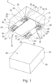
- Figure 1 shows a connection part 10.
- connection part 10 comprises a body portion 12.
- connection surface 14 is arranged on the body portion 12.
- connection surface 14 is formed by an adhesive layer 16 being arranged on the body portion 12.
- the adhesive layer 16 comprises an adhesive tape 18.
- connection part 10 further comprises four positioning protrusions 20.
- the positioning protrusions 20 are located at a distance d away from an edge of the connection surface 14 respectively. Put otherwise, the positioning protrusions 20 are located outside the connection surface 14.
- the positioning protrusions 20 are leg-shaped.
- the positioning protrusions 20 substantially extend parallel to the connection surface 14.
- a first end portion 22 of each of the positioning protrusions 20 is connected to the body portion 12.
- each of the positioning protrusions 20 comprises an elastically deformable section 24.
- the positioning protrusions 20 are movably connected to the body portion 12 via these sections 24.
- the positioning protrusions 20 and the body portion 12 are formed as an integral structure. More precisely, the connection part 10 is an injection molded part made from plastics material. Thus, the body portion 12 and the positioning protrusions 20 are formed together in a single injection molding process.
- the positioning protrusions 20 are shown in a pre-assembly position. In this position, the positioning protrusions 20 at least partially protrude with respect to the connection surface 14.
- each positioning protrusion 20 being arranged opposite the respective first end portion 22 protrude over the connecting surface 14.
- the positioning protrusions 20 Due to the movability of the positioning protrusions 20, they can also assume an assembly position wherein the positioning protrusions 20 are flush with the connection surface 14 or are retracted with respect to the connection surface 14.
- connection part 10 also comprises a securing means 28.
- a securing means 28 is provided for each of the positioning protrusions 20.
- each securing means 28 comprises a securing protrusion 30 being located on the corresponding positioning protrusion 20 and a securing depression 32 being located on the body portion 12.
- the securing means 28 is configured for securing the corresponding positioning protrusion 20 in the assembly position.
- each of the securing protrusions 30 engages the corresponding securing depression 32.
- the securing means 28 are configured such that the state in which the corresponding positioning protrusion 20 is secured on the body portion 12 may be reached by applying a force equaling a predefined mounting force. This means that the positioning protrusions 20 will be moved into the assembly position when the connecting part 10 is mounted to a mating part as will be explained further below.
- This force is used for moving the securing protrusions 30 into the corresponding securing depressions 32, thereby also elastically deforming the elastically deformable sections 24.
- the securing means 28 is configured for producing a sound when the securing protrusion 30 reaches the corresponding securing depression.
- connection part 10 is configured for being connected to a mating part 34 via the connection surface 14.
- the mating part 34 has a mating part body 36.
- a counter-connection surface 38 is provided on the mating part body 36 .
- connection part 10 and the mating part 34 are configured for being connected via the connection surface 14 and the counter-connection surface 38.
- connection part 10 and the mating part 34 form a part connection 40.
- connection part 10 is connected to connection part 10 and the mating part 34 .
- a part connection 40 is produced.
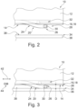
- Figure 2 shows a situation corresponding to Figure 1 , wherein the connection part 10 and the mating part 34 do not at all contact each other.
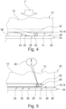
- a first step of the method is illustrated in Figure 3 .
- the first step comprises bringing the positioning protrusions 20 in contact with the mating part body 36.
- the positioning protrusions 20 are in the pre-assembly position, i.e. they protrude with respect to the connection surface 14.
- connection surface 14 and the counter-connection surface 38 are arranged within a predefined distance D.
- the positioning protrusions 20 may slide on the mating part body 36 in order to bring the connection surface 14 and the counter-connection surface 38 in a desired relative position.
- connection surface 14 and the counter-connection surface 38 are arranged within the predefined distance D.
- connection part 10 Thereafter, a mounting force F is applied to the connection part 10.
- the mounting force F is directed towards the mating part 34 (cf. Figure 4 ).
- the mounting force F is oriented perpendicular to the connection surface 14 and the counter-connection surface 38.
- connection part 10 and the mating part 34 are pressed towards one another.
- the elastically deformable sections 24 of the positioning protrusion 20 are deformed elastically such that the positioning protrusions 20 are bent towards the body portion 12 of the connection part 10.
- connection surface 14 and the counter-connection surface 38 contact each other (cf. Figure 5 ).
- the positioning protrusions 20 reach the assembly position in which they are retracted with respect to the connection surface 14.
- each of the securing protrusions 30 engages the corresponding securing depression 32. This means that the positioning protrusions 20 are secured in the assembly position.
- the securing protrusions 30 produce a sound 46 when engaging the corresponding securing depression 32.
- connection part 10 and the mating part 34 is purely illustrative.
- the connection part 10 and the mating part 34 can have any form as long as the connecting surface 14 and the counter-connection surface 38 are suitable for contacting each other.
- connection part 10 and/or the mating part 34 are formed as portions of a respective bigger part.
Landscapes
- Engineering & Computer Science (AREA)
- Mechanical Engineering (AREA)
- General Engineering & Computer Science (AREA)
- Connection Of Plates (AREA)
- Standing Axle, Rod, Or Tube Structures Coupled By Welding, Adhesion, Or Deposition (AREA)
Description
- The present disclosure relates to a connection part for an industrial assembly process.
- Moreover, the present disclosure is directed to a part connection comprising such a connection part and a mating part.
- Additionally, the present disclosure relates to a method for adhesively connecting a connection part and a mating part.
- Such part connections, connection parts, mating parts and methods for adhesively connecting a connection part and a mating part are omnipresent in industrial assembly processes, e.g. in the automotive sector.
- Adhesive connections, for example adhesive connections comprising an adhesive tape, are often used since such connections can be established in a simple manner without the need of specific tools.
- However, when using adhesive connections, care has to be taken that the connection part and the mating part are in the desired relative position upon the first contact between these parts. This is due to the fact that adhesive connections, especially adhesive connections comprising an adhesive tape, usually are established upon this first contact. Normally, it is not possible to further align the connection part and the mating part once the connection is established. Consequently, when manually establishing such an adhesive connection, a high degree of attention and concentration is necessary. When automatically establishing such an adhesive connection, elaborate and precise control methods have to be used.
- A connection part according to the preamble of claim 1 is for example known from
US 2006/0021242 A1 . - It is therefore an objective of the present disclosure to provide parts and methods necessary for an adhesive connection that can be established in a precise and simple manner.
- The problem is at least partially solved or alleviated by the subject matter of the independent claims of the present disclosure, wherein further examples are incorporated in the dependent claims.
- According to a first aspect, there is provided a connection part for an industrial assembly process. The connection part has a body portion and a connection surface being arranged on the body portion. The connection surface is configured for being connected to a mating part. The connection part further comprises at least one positioning protrusion being located at a distance away from an edge of the connection surface and being movably connected to the body portion. The at least one positioning protrusion is leg-shaped, one end portion thereof being connected to the body portion. In a pre-assembly position the positioning protrusion at least partially protrudes with respect to the connection surface, and in an assembly position the positioning protrusion is flush with the connection surface or is retracted with respect to the connection surface. In this context, a movable connection between the body portion and the positioning protrusion may for example be realized by a connection allowing the positioning protrusion to pivot or to slide with respect to the body portion. The movable connection may thus comprise a joint and/or a linear guide. In that one end of the leg-shaped positioning protrusion is connected to the body portion, the positioning protrusion is reliably connected to the body portion and movable at the same time. The connection surface may have any form. For example, the connection surface is flat or curved. The fact that the positioning protrusion is arranged at a distance away from an edge of the connection surface means that the positioning protrusion is not configured for connecting the connection part to the mating part. Such a connection part may be connected to the mating part in a simple and exact manner since in the pre-assembly position of the positioning protrusion, the positioning protrusion prevents an undesired contact between the connection part and the mating part. In other words, the positioning protrusion keeps the connection surface of the connection part at a predefined distance from the mating part. This facilitates the positioning of the connection part relative to the mating part. Once the desired relative position has been reached, the positioning protrusion is retracted such that a connection may be established via the connection surface of the connection part. The positioning protrusion does not hinder this connection and does not have any negative influences thereon.
- The industrial assembly process may be an automotive assembly process.
- In an example, the connection surface may be positioned at a base surface of the body portion. The connection surface may extend along a length of the base surface. Alternatively or additionally, the connection surface may extend along a width of the base surface. It is also possible that the connection surface extends along a width and/or a length of an intermediate portion of the base surface. Such connection surfaces allow for stable and reliable connections.
- In an example, the connection surface is formed by an adhesive layer being arranged on the body portion. Such an adhesive layer is suitable for providing a stable and precise connection.
- In an example, the adhesive layer comprises an adhesive tape. This is a simple and reliable manner for providing an adhesive layer.
- In an example, the at least one positioning protrusion is movably connected to the body portion via an elastically deformable section of the body portion and/or an elastically deformable section of the positioning protrusion. Such a connection can be produced at comparatively low costs. Moreover, by choosing an appropriate material and an appropriate geometry of the deformable section, the movability can be adjusted depending on the specific application.
- For example, the leg-shaped positioning protrusion may substantially extend in parallel to the connection surface. In this case, the end portion of the positioning protrusion not being connected to the body portion may protrude over the connection surface in the pre-assembly position.
- The leg-shaped positioning protrusion may be at least partially elastically deformable.
- In an example, at least two positioning protrusion may be provided on the body portion of the connection part. The positioning protrusions may be positioned on opposing sides of the connection surface. Consequently, undesired contacts between the connection surface of the connection part and the mating part are avoided with enhanced reliability. The at least two positioning protrusions may be designated a first positioning protrusion and a second positioning protrusion.
- In another example, at least three positioning protrusions are provided on the body portion of the connection part. In such a case, the connection part may assume a statically well-defined state when being in the pre-assembly position and contacting a mating part. Thus, the connection surface is kept at a predefined distance from the mating part. Of course, also more positioning protrusions can be provided.
- In an example, the connection part comprises a securing means. In the assembly position, the at least one positioning protrusion is secured on the body portion by the securing means. The positioning protrusion is thus held in the assembly position. Consequently, it is not able to return to the pre-assembly position once it has reached the assembly position. This also means that the positioning protrusion does not influence a connection between the connection surface and a mating part. Such a connection is reliable and stable.
- In an example, the securing means comprises a securing protrusion and a corresponding securing depression for each of the positioning protrusions. In the assembly position, the securing protrusion engages the securing depression and in the pre-assembly position the securing protrusion and the securing depression are disengaged. Such a securing means is simple in design and reliable in operation. In this context, the securing protrusion may be pushed into engagement with the corresponding securing depression when pressing the connection surface against a corresponding surface of the mating part for establishing a connection. The securing protrusion and the corresponding securing depression are shaped such that the securing protrusion is not able to leave the securing depression.
- In an example, the securing means may comprise a snap-on mechanism or an interference fit mechanism. Consequently, the positioning protrusion may be reliably secured on the body portion.
- In an example, the securing means may be configured for producing a sound when reaching the state in which the at least one positioning protrusion is secured on the body portion. This sound may be a click sound or a clack sound. Consequently, a user can be sure that the positioning protrusion is secured on the body portion without having to visually verify this fact. In the example where the securing means comprises a securing protrusion and a securing depression, the sound may be produced by the securing protrusion entering the securing depression.
- In an example, the securing means is configured such that the state in which the at least one positioning protrusion is secured on the body portion is reached by applying a force equaling, exceeding or being smaller than a predefined mounting force. If the force equals the mounting force or is smaller than the mounting force, the positioning protrusion may be transferred into the secured position by simply mounting the connection part on the mating part. No additional force or effort is necessary. If the force exceeds the mounting force, the force for bringing the positioning protrusion into the secured state creates a predefined resistance when mounting the connection part to the mating part. This prevents undesired connections. In a case in which the securing means comprises a securing protrusion and a securing depression, the force being necessary for moving the securing protrusion into the securing depression may be adjusted by choosing an appropriate geometry of the securing protrusion and the securing depression and/or by choosing appropriate materials.
- In an example, the body portion and the positioning protrusion are formed as an integral structure. Thus, no assembly is necessary.
- The body portion and the positioning protrusions may also be produced as an integral structure, e.g. by injection molding, casting or by a generative manufacturing process.
- According to a second aspect, there is provided a part connection comprising a connection part according to the present disclosure and a mating part. The mating part has a mating part body with a counter-connection surface. The connection part and the mating part are connected via the connection surface and the counter-connection surface. To this end, an adhesive layer, e.g. in the form of an adhesive tape, may be provided on at least one of the connection surface and the counter-connection surface. Such a part connection is highly reliable. Moreover, since a connection part according to the present disclosure is used, the mating part and the connection part may be positioned relative to one another with high precision. The connection may be established in a simple manner.
- According to a third aspect, there is provided a method for adhesively connecting a connection part and a mating part. The connection part has a body portion, a connection surface being arranged on the body portion, and at least one positioning protrusion being located at a distance away from an edge of the connection surface and being movably connected to the body portion. The at least one positioning protrusion is leg-shaped, wherein one end portion thereof is connected to the body portion. The mating part has a mating part body with a counter-connection surface. The method comprises:
- bringing the at least one positioning protrusion in contact with the mating part body, wherein the at least one positioning protrusion at least partially protrudes with respect to the connection surface such that the connection surface and the counter-connection surface are arranged within a predefined distance from each other,
- pressing the connection part and the mating part towards one another until the connection surface and the counter-connection surface contact each other and such that the at least one positioning protrusion is moved to a position in which it is flush with the connection surface or is retracted with respect to the connection surface.
- For establishing the adhesive connection, an adhesive layer, e.g. in the form of an adhesive tape, may be provided on at least one of the connection surface and the counter-connection surface.
- In an example, the method comprises sliding the at least one positioning protrusion on the mating part body and bringing the connection surface and the counter-connection surface in a desired relative position while the connection surface and the counter-connection surface are arranged within the predefined distance. This facilitates establishing a precise connection. The positioning protrusion may be used as a sliding block. As before, undesired contacts between the connection surface and the counter-connection surface are avoided.
- In an example, pressing the connection part and the mating part towards one another comprises applying a mounting force to at least one of the connection part and the mating part. The mounting force is oriented non-parallel to the connection surface. It is obvious that the mounting force it applied to one of the parts and that a corresponding counter-force needs to be applied to the respective other part. The mounting force may be oriented perpendicular to at least one of the connection surface and the counter-connection surface. The mounting force is to be understood as the force necessary for establishing the connection between the connection part and the mating part.
- It should be noted that the above examples may be combined with each other irrespective of the aspect involved. Accordingly, the method may be combined with structural features and, likewise, the connection part and the part connection may be combined with features described above with regard to the method.
- These and other aspects of the present disclosure will become apparent from and elucidated with reference to the examples described hereinafter.
- Examples of the disclosure will be described in the following with reference to the following drawings.
- Fig. 1
- shows a connection part according to the present disclosure and a mating part, wherein the connection part and the mating parte are in a disconnected state, and
- Fig. 2 to Fig. 5
- partially shows the connection part and the mating part of
Figure 1 along a direction II during the performance of a method according to the present disclosure for forming a part connection according to the present disclosure. - The figures are merely schematic representations and serve only to illustrate examples of the disclosure. Identical or equivalent elements are in principle provided with the same reference signs.
-
Figure 1 shows aconnection part 10. - The
connection part 10 comprises abody portion 12. - A
connection surface 14 is arranged on thebody portion 12. - In the present example, the
connection surface 14 is formed by an adhesive layer 16 being arranged on thebody portion 12. - The adhesive layer 16 comprises an adhesive tape 18.
- The
connection part 10 further comprises fourpositioning protrusions 20. - The positioning protrusions 20 are located at a distance d away from an edge of the
connection surface 14 respectively. Put otherwise, the positioningprotrusions 20 are located outside theconnection surface 14. - In the present example, the positioning
protrusions 20 are leg-shaped. - The positioning protrusions 20 substantially extend parallel to the
connection surface 14. - A
first end portion 22 of each of thepositioning protrusions 20 is connected to thebody portion 12. - Moreover, each of the
positioning protrusions 20 comprises an elasticallydeformable section 24. - Thus, the positioning
protrusions 20 are movably connected to thebody portion 12 via thesesections 24. - In the present example, the positioning
protrusions 20 and thebody portion 12 are formed as an integral structure. More precisely, theconnection part 10 is an injection molded part made from plastics material. Thus, thebody portion 12 and thepositioning protrusions 20 are formed together in a single injection molding process. - In
Figure 1 , the positioningprotrusions 20 are shown in a pre-assembly position. In this position, the positioningprotrusions 20 at least partially protrude with respect to theconnection surface 14. - In the example,
second end portions 26 of each positioningprotrusion 20 being arranged opposite the respectivefirst end portion 22 protrude over the connectingsurface 14. - Due to the movability of the
positioning protrusions 20, they can also assume an assembly position wherein thepositioning protrusions 20 are flush with theconnection surface 14 or are retracted with respect to theconnection surface 14. - The
connection part 10 also comprises a securing means 28. - More precisely, a securing means 28 is provided for each of the positioning
protrusions 20. - In the present example, each securing means 28 comprises a securing
protrusion 30 being located on thecorresponding positioning protrusion 20 and a securingdepression 32 being located on thebody portion 12. - The securing means 28 is configured for securing the
corresponding positioning protrusion 20 in the assembly position. - To this end, each of the securing
protrusions 30 engages the corresponding securingdepression 32. - Obviously, in the pre-assembly position as shown in
Figure 2 , the securingprotrusions 30 and the securingdepressions 32 are disengaged. - Furthermore, the securing means 28 are configured such that the state in which the
corresponding positioning protrusion 20 is secured on thebody portion 12 may be reached by applying a force equaling a predefined mounting force. This means that thepositioning protrusions 20 will be moved into the assembly position when the connectingpart 10 is mounted to a mating part as will be explained further below. - This force is used for moving the securing
protrusions 30 into the corresponding securingdepressions 32, thereby also elastically deforming the elasticallydeformable sections 24. - Additionally, the securing means 28 is configured for producing a sound when the securing
protrusion 30 reaches the corresponding securing depression. Thus, a user can be sure that thecorresponding positioning protrusion 20 is secured in the corresponding assembly position. The user receives an acoustic confirmation. Consequently, no visual inspection is necessary. - The
connection part 10 is configured for being connected to amating part 34 via theconnection surface 14. - Also the
mating part 34 has amating part body 36. - On the mating part body 36 a
counter-connection surface 38 is provided. - The
connection part 10 and themating part 34 are configured for being connected via theconnection surface 14 and thecounter-connection surface 38. - Once connected, the
connection part 10 and themating part 34 form apart connection 40. - In the following, with additional reference to
Figures 2 to 5 , a method for adhesively connecting theconnection part 10 and themating part 34 is explained. In other words, using the method, apart connection 40 is produced. -
Figure 2 shows a situation corresponding toFigure 1 , wherein theconnection part 10 and themating part 34 do not at all contact each other. - A first step of the method is illustrated in
Figure 3 . - The first step comprises bringing the
positioning protrusions 20 in contact with themating part body 36. - The positioning protrusions 20 are in the pre-assembly position, i.e. they protrude with respect to the
connection surface 14. - Consequently, the
connection surface 14 and thecounter-connection surface 38 are arranged within a predefined distance D. - In this configuration, the positioning
protrusions 20 may slide on themating part body 36 in order to bring theconnection surface 14 and thecounter-connection surface 38 in a desired relative position. - Possible sliding directions are indicated by
arrows - While sliding, the
connection surface 14 and thecounter-connection surface 38 are arranged within the predefined distance D. - Thereafter, a mounting force F is applied to the
connection part 10. The mounting force F is directed towards the mating part 34 (cf.Figure 4 ). - More precisely, the mounting force F is oriented perpendicular to the
connection surface 14 and thecounter-connection surface 38. - As a consequence of the mounting force F, the
connection part 10 and themating part 34 are pressed towards one another. In this context, the elasticallydeformable sections 24 of thepositioning protrusion 20 are deformed elastically such that thepositioning protrusions 20 are bent towards thebody portion 12 of theconnection part 10. - The mounting force F is applied until the
connection surface 14 and thecounter-connection surface 38 contact each other (cf.Figure 5 ). In this state, the positioningprotrusions 20 reach the assembly position in which they are retracted with respect to theconnection surface 14. - Moreover, each of the securing
protrusions 30 engages the corresponding securingdepression 32. This means that thepositioning protrusions 20 are secured in the assembly position. - The securing
protrusions 30 produce a sound 46 when engaging the corresponding securingdepression 32. - It is noted that in the example shown in the figures, the form of the
connection part 10 and themating part 34 is purely illustrative. Theconnection part 10 and themating part 34 can have any form as long as the connectingsurface 14 and thecounter-connection surface 38 are suitable for contacting each other. - In other examples, the
connection part 10 and/or themating part 34 are formed as portions of a respective bigger part. - Other variations to the disclosed examples can be understood and effected by those skilled in the art in practicing the claimed disclosure, from the study of the drawings, the disclosure, and the appended claims. In the claims the word "comprising" does not exclude other elements or steps and the indefinite article "a" or "an" does not exclude a plurality. The mere fact that certain measures are recited in mutually different dependent claims does not indicate that a combination of these measures cannot be used to advantage. Any reference signs in the claims should not be construed as limiting the scope of the claims.
-
- 10
- connection part
- 12
- body portion
- 14
- connecting surface
- 16
- adhesive layer
- 18
- adhesive tape
- 20
- positioning protrusion
- 22
- first end portion
- 24
- elastically deformable section
- 26
- second end portion
- 28
- securing means
- 30
- securing protrusion
- 32
- securing depression
- 34
- mating part
- 36
- mating part body
- 38
- counter-connection surface
- 40
- part connection
- 42
- arrow
- 44
- arrow
- 46
- sound
- d
- distance
- D
- predefined distance
- F
- mounting force
Claims (14)
- A connection part (10) for an industrial assembly process, the connection part (10) havinga body portion (12) and a connection surface (14) being arranged on the body portion (12), the connection surface (14) being configured for being connected to a mating part (34), and at least one positioning protrusion (20) being located at a distance (d) away from an edge of the connection surface (14) and being movably connected to the body portion (12),wherein in a pre-assembly position the positioning protrusion (20) at least partially protrudes with respect to the connection surface (14), and in an assembly position the positioning protrusion (20) is flush with the connection surface (14) or is retracted with respect to the connection surface (14),characterized in that the at least one positioning protrusion (20) is leg-shaped, one end portion (22) thereof being connected to the body portion (12).
- The connection part (10) according to claim 1, wherein the connection surface (14) is formed by an adhesive layer (16) being arranged on the body portion (12).
- The connection part (10) according to claim 2, wherein the adhesive layer (16) comprises an adhesive tape (18).
- The connection part (10) according to any one of the preceding claims, wherein the at least one positioning protrusion (20) is movably connected to the body portion (12) via an elastically deformable section of the body portion (12) and/or an elastically deformable section (24) of the positioning protrusion (20).
- The connection part (10) according to any one of the preceding claims, wherein at least two positioning protrusions (20) are provided on the body portion (12).
- The connection part (10) according to any of the preceding claims, comprising a securing means (28), wherein in the assembly position the at least one positioning protrusion (20) is secured on the body portion (12) by the securing means (28).
- The connection part (10) according to claim 6, wherein the securing means (28) comprises a securing protrusion (30) and a corresponding securing depression (32) for each of SE:TOP
the positioning protrusions (20), wherein in the assembly position the securing protrusion (30) engages the securing depression (32) and in the pre-assembly position the securing protrusion (30) and the securing depression (32) are disengaged. - The connection part (10) according to claim 6 or claim 7, wherein the securing means (28) is configured for producing a sound (46) when reaching the state in which the at least one positioning protrusion (20) is secured on the body portion (12).
- The connection part (10) according to any one of claims 6 to 8, wherein the securing means (28) is configured such that the state in which the at least one positioning protrusion (20) is secured on the body portion (12) is reached by applying a force equaling, exceeding or being smaller than a predefined mounting force (F).
- The connection part (10) according to any one of the preceding claims, wherein the body portion (12) and the positioning protrusion (20) are formed as an integral structure.
- A part connection (40) comprising a connection part (10) according to any one of the previous claims and a mating part (34) having a mating part body (36) with a counter-connection surface (38), wherein the connection part (10) and the mating part (34) are connected via the connection surface (14) and the counter-connection surface (38).
- Method for adhesively connecting a connection part (10) and a mating part (34),the connection part (10) having a body portion (12), a connection surface (14) being arranged on the body portion (12), and at least one positioning protrusion (20) being located at a distance (d) away from an edge of the connection surface (14), being movably connected to the body portion (12), and being leg-shaped, wherein one end portion (22) thereof is connected to the body portion (12), andthe mating part (34) having a mating part body (36) with a counter-connection surface (38), the method comprising:- bringing the at least one positioning protrusion (20) in contact with the mating part body (36), wherein the at least one positioning protrusion (20) at least partially protrudes with respect to the connection surface (14) such that the connection surface (14) and the counter-connection surface (38) are arranged within a predefined distance (D) from each other,- pressing the connection part (10) and the mating part (34) towards one another until the connection surface (14) and the counter-connection surface (38) contact each other and such that the at least one positioning protrusion (20) is moved to a position in which it is flush with the connection surface (14) or is retracted with respect to the connection surface (14).
- The method according to claim 12, comprising: sliding the at least one positioning protrusion (20) on the mating part body (36) and bringing the connection surface (14) and the counter-connection surface (38) in a desired relative position while the connection surface (14) and the counter-connection surface (38) are arranged within the predefined distance (D).
- The method according to claim 12 or 13, wherein pressing the connection part (10) and the mating part (34) towards one another comprises applying a mounting force (F) to at least one of the connection part (10) and the mating part (34), the mounting force (F) being oriented non-parallel to the connection surface (14).
Priority Applications (3)
| Application Number | Priority Date | Filing Date | Title |
|---|---|---|---|
| EP21214723.5A EP4197747B1 (en) | 2021-12-15 | 2021-12-15 | Connection part for an industrial assembly process, part connection and method for adhesively connecting a connection part and a mating part |
| CN202211596981.1A CN116263177A (en) | 2021-12-15 | 2022-12-12 | Connecting part for industrial assembly process, part connecting piece for connecting part and mating part, and bonding connection method thereof |
| US18/080,083 US20230184277A1 (en) | 2021-12-15 | 2022-12-13 | Connection part for an industrial assembly process, part connection and method for adhesively connecting a connection part and a mating part |
Applications Claiming Priority (1)
| Application Number | Priority Date | Filing Date | Title |
|---|---|---|---|
| EP21214723.5A EP4197747B1 (en) | 2021-12-15 | 2021-12-15 | Connection part for an industrial assembly process, part connection and method for adhesively connecting a connection part and a mating part |
Publications (2)
| Publication Number | Publication Date |
|---|---|
| EP4197747A1 EP4197747A1 (en) | 2023-06-21 |
| EP4197747B1 true EP4197747B1 (en) | 2024-03-13 |
Family
ID=78916775
Family Applications (1)
| Application Number | Title | Priority Date | Filing Date |
|---|---|---|---|
| EP21214723.5A Active EP4197747B1 (en) | 2021-12-15 | 2021-12-15 | Connection part for an industrial assembly process, part connection and method for adhesively connecting a connection part and a mating part |
Country Status (3)
| Country | Link |
|---|---|
| US (1) | US20230184277A1 (en) |
| EP (1) | EP4197747B1 (en) |
| CN (1) | CN116263177A (en) |
Family Cites Families (3)
| Publication number | Priority date | Publication date | Assignee | Title |
|---|---|---|---|---|
| US5593120A (en) * | 1994-11-21 | 1997-01-14 | Minnesota Mining And Manufacturing Company | Quick-mounting fastening assembly |
| ES2423212T3 (en) * | 2004-07-23 | 2013-09-18 | Dr. Johannes Heidenhain Gmbh | Component, in particular sensor, and method for gluing the component |
| KR101063058B1 (en) * | 2010-10-28 | 2011-09-07 | 박민식 | Attachable pad for supporter |
-
2021
- 2021-12-15 EP EP21214723.5A patent/EP4197747B1/en active Active
-
2022
- 2022-12-12 CN CN202211596981.1A patent/CN116263177A/en active Pending
- 2022-12-13 US US18/080,083 patent/US20230184277A1/en active Pending
Also Published As
| Publication number | Publication date |
|---|---|
| EP4197747A1 (en) | 2023-06-21 |
| CN116263177A (en) | 2023-06-16 |
| US20230184277A1 (en) | 2023-06-15 |
Similar Documents
| Publication | Publication Date | Title |
|---|---|---|
| US10440846B2 (en) | Bracket and assembly structure for bracket | |
| EP2578375A1 (en) | Clip, method for producing clip, and device for producing clip | |
| EP4197747B1 (en) | Connection part for an industrial assembly process, part connection and method for adhesively connecting a connection part and a mating part | |
| US20100284735A1 (en) | Connecting element for snap connections | |
| US7382630B2 (en) | Board-mounting device | |
| JP5368293B2 (en) | Manufacturing method of substrate with base | |
| EP3675289B1 (en) | Connector | |
| US20180310420A1 (en) | Assembly structure for bracket | |
| US20140216910A1 (en) | Push switch | |
| CN114060375A (en) | Fastener and shell device comprising same | |
| JP4046898B2 (en) | Manufacturing method of insert molded product | |
| JP2006289661A (en) | Method and apparatus for manufacturing insert resin molded product | |
| JPH0512074Y2 (en) | ||
| KR20060048260A (en) | Punching device and its punching die | |
| CN219550793U (en) | Buckle structure, face frame subassembly and air conditioner | |
| CN220947859U (en) | Mounting structure and vehicle | |
| JP5122382B2 (en) | How to attach metal parts to electronic parts | |
| JPH0532042U (en) | MALL JOINT CLIP | |
| US11739777B2 (en) | Alignment feature for an elastic averaging alignment system | |
| CN218557296U (en) | Hot punching mechanism of automobile decoration film | |
| US20240084887A1 (en) | Wiper motor, method for assembling a wiper motor, and assembly tool | |
| CN219119583U (en) | Coupling assembling and vehicle | |
| JPS6030526A (en) | Method of press work | |
| CN216580748U (en) | Adjusting mechanism, tail assembly of vehicle and vehicle | |
| WO2008062573A1 (en) | Tube clamp |
Legal Events
| Date | Code | Title | Description |
|---|---|---|---|
| PUAI | Public reference made under article 153(3) epc to a published international application that has entered the european phase |
Free format text: ORIGINAL CODE: 0009012 |
|
| STAA | Information on the status of an ep patent application or granted ep patent |
Free format text: STATUS: REQUEST FOR EXAMINATION WAS MADE |
|
| 17P | Request for examination filed |
Effective date: 20220908 |
|
| AK | Designated contracting states |
Kind code of ref document: A1 Designated state(s): AL AT BE BG CH CY CZ DE DK EE ES FI FR GB GR HR HU IE IS IT LI LT LU LV MC MK MT NL NO PL PT RO RS SE SI SK SM TR |
|
| RIC1 | Information provided on ipc code assigned before grant |
Ipc: B29C 65/50 20060101ALN20230628BHEP Ipc: B29C 65/58 20060101ALN20230628BHEP Ipc: B29C 65/48 20060101ALN20230628BHEP Ipc: F16B 11/00 20060101ALI20230628BHEP Ipc: B29C 65/00 20060101AFI20230628BHEP |
|
| RIC1 | Information provided on ipc code assigned before grant |
Ipc: B29C 65/50 20060101ALN20230725BHEP Ipc: B29C 65/58 20060101ALN20230725BHEP Ipc: B29C 65/48 20060101ALN20230725BHEP Ipc: F16B 11/00 20060101ALI20230725BHEP Ipc: B29C 65/00 20060101AFI20230725BHEP |
|
| RIC1 | Information provided on ipc code assigned before grant |
Ipc: B29C 65/50 20060101ALN20230813BHEP Ipc: B29C 65/58 20060101ALN20230813BHEP Ipc: B29C 65/48 20060101ALN20230813BHEP Ipc: B29C 65/78 20060101ALI20230813BHEP Ipc: F16B 11/00 20060101ALI20230813BHEP Ipc: B29C 65/00 20060101AFI20230813BHEP |
|
| GRAP | Despatch of communication of intention to grant a patent |
Free format text: ORIGINAL CODE: EPIDOSNIGR1 |
|
| STAA | Information on the status of an ep patent application or granted ep patent |
Free format text: STATUS: GRANT OF PATENT IS INTENDED |
|
| INTG | Intention to grant announced |
Effective date: 20230922 |
|
| GRAS | Grant fee paid |
Free format text: ORIGINAL CODE: EPIDOSNIGR3 |
|
| GRAA | (expected) grant |
Free format text: ORIGINAL CODE: 0009210 |
|
| STAA | Information on the status of an ep patent application or granted ep patent |
Free format text: STATUS: THE PATENT HAS BEEN GRANTED |
|
| AK | Designated contracting states |
Kind code of ref document: B1 Designated state(s): AL AT BE BG CH CY CZ DE DK EE ES FI FR GB GR HR HU IE IS IT LI LT LU LV MC MK MT NL NO PL PT RO RS SE SI SK SM TR |
|
| REG | Reference to a national code |
Ref country code: GB Ref legal event code: FG4D |
|
| REG | Reference to a national code |
Ref country code: CH Ref legal event code: EP |
|
| P01 | Opt-out of the competence of the unified patent court (upc) registered |
Effective date: 20240219 |
|
| REG | Reference to a national code |
Ref country code: DE Ref legal event code: R096 Ref document number: 602021010371 Country of ref document: DE |
|
| REG | Reference to a national code |
Ref country code: IE Ref legal event code: FG4D |