EP2578375A1 - Clip, method for producing clip, and device for producing clip - Google Patents
Clip, method for producing clip, and device for producing clip Download PDFInfo
- Publication number
- EP2578375A1 EP2578375A1 EP11786293.8A EP11786293A EP2578375A1 EP 2578375 A1 EP2578375 A1 EP 2578375A1 EP 11786293 A EP11786293 A EP 11786293A EP 2578375 A1 EP2578375 A1 EP 2578375A1
- Authority
- EP
- European Patent Office
- Prior art keywords
- mold
- attachment
- leg
- clip
- flange portion
- Prior art date
- Legal status (The legal status is an assumption and is not a legal conclusion. Google has not performed a legal analysis and makes no representation as to the accuracy of the status listed.)
- Withdrawn
Links
- 238000004519 manufacturing process Methods 0.000 title claims description 19
- 239000011347 resin Substances 0.000 claims abstract description 18
- 229920005989 resin Polymers 0.000 claims abstract description 18
- 238000001746 injection moulding Methods 0.000 claims abstract description 14
- 239000000463 material Substances 0.000 claims abstract description 11
- 238000007789 sealing Methods 0.000 claims description 22
- 230000013011 mating Effects 0.000 claims description 6
- 238000000465 moulding Methods 0.000 description 11
- 125000006850 spacer group Chemical group 0.000 description 9
- 238000000034 method Methods 0.000 description 5
- 238000002347 injection Methods 0.000 description 2
- 239000007924 injection Substances 0.000 description 2
- 238000012986 modification Methods 0.000 description 2
- 230000004048 modification Effects 0.000 description 2
- 229920006324 polyoxymethylene Polymers 0.000 description 2
- XLYOFNOQVPJJNP-UHFFFAOYSA-N water Substances O XLYOFNOQVPJJNP-UHFFFAOYSA-N 0.000 description 2
- 229930182556 Polyacetal Natural products 0.000 description 1
- 238000004458 analytical method Methods 0.000 description 1
- 238000004891 communication Methods 0.000 description 1
- 239000000470 constituent Substances 0.000 description 1
- 238000013461 design Methods 0.000 description 1
- 238000002474 experimental method Methods 0.000 description 1
- 238000012856 packing Methods 0.000 description 1
- 230000000717 retained effect Effects 0.000 description 1
- 230000008961 swelling Effects 0.000 description 1
- 239000011800 void material Substances 0.000 description 1
Images


Classifications
-
- F—MECHANICAL ENGINEERING; LIGHTING; HEATING; WEAPONS; BLASTING
- F16—ENGINEERING ELEMENTS AND UNITS; GENERAL MEASURES FOR PRODUCING AND MAINTAINING EFFECTIVE FUNCTIONING OF MACHINES OR INSTALLATIONS; THERMAL INSULATION IN GENERAL
- F16B—DEVICES FOR FASTENING OR SECURING CONSTRUCTIONAL ELEMENTS OR MACHINE PARTS TOGETHER, e.g. NAILS, BOLTS, CIRCLIPS, CLAMPS, CLIPS OR WEDGES; JOINTS OR JOINTING
- F16B19/00—Bolts without screw-thread; Pins, including deformable elements; Rivets
-
- B—PERFORMING OPERATIONS; TRANSPORTING
- B29—WORKING OF PLASTICS; WORKING OF SUBSTANCES IN A PLASTIC STATE IN GENERAL
- B29C—SHAPING OR JOINING OF PLASTICS; SHAPING OF MATERIAL IN A PLASTIC STATE, NOT OTHERWISE PROVIDED FOR; AFTER-TREATMENT OF THE SHAPED PRODUCTS, e.g. REPAIRING
- B29C45/00—Injection moulding, i.e. forcing the required volume of moulding material through a nozzle into a closed mould; Apparatus therefor
- B29C45/17—Component parts, details or accessories; Auxiliary operations
- B29C45/40—Removing or ejecting moulded articles
- B29C45/44—Removing or ejecting moulded articles for undercut articles
-
- B—PERFORMING OPERATIONS; TRANSPORTING
- B29—WORKING OF PLASTICS; WORKING OF SUBSTANCES IN A PLASTIC STATE IN GENERAL
- B29C—SHAPING OR JOINING OF PLASTICS; SHAPING OF MATERIAL IN A PLASTIC STATE, NOT OTHERWISE PROVIDED FOR; AFTER-TREATMENT OF THE SHAPED PRODUCTS, e.g. REPAIRING
- B29C45/00—Injection moulding, i.e. forcing the required volume of moulding material through a nozzle into a closed mould; Apparatus therefor
- B29C45/03—Injection moulding apparatus
-
- F—MECHANICAL ENGINEERING; LIGHTING; HEATING; WEAPONS; BLASTING
- F16—ENGINEERING ELEMENTS AND UNITS; GENERAL MEASURES FOR PRODUCING AND MAINTAINING EFFECTIVE FUNCTIONING OF MACHINES OR INSTALLATIONS; THERMAL INSULATION IN GENERAL
- F16B—DEVICES FOR FASTENING OR SECURING CONSTRUCTIONAL ELEMENTS OR MACHINE PARTS TOGETHER, e.g. NAILS, BOLTS, CIRCLIPS, CLAMPS, CLIPS OR WEDGES; JOINTS OR JOINTING
- F16B21/00—Means for preventing relative axial movement of a pin, spigot, shaft or the like and a member surrounding it; Stud-and-socket releasable fastenings
- F16B21/06—Releasable fastening devices with snap-action
- F16B21/08—Releasable fastening devices with snap-action in which the stud, pin, or spigot has a resilient part
- F16B21/086—Releasable fastening devices with snap-action in which the stud, pin, or spigot has a resilient part the shank of the stud, pin or spigot having elevations, ribs, fins or prongs intended for deformation or tilting predominantly in a direction perpendicular to the direction of insertion
-
- F—MECHANICAL ENGINEERING; LIGHTING; HEATING; WEAPONS; BLASTING
- F16—ENGINEERING ELEMENTS AND UNITS; GENERAL MEASURES FOR PRODUCING AND MAINTAINING EFFECTIVE FUNCTIONING OF MACHINES OR INSTALLATIONS; THERMAL INSULATION IN GENERAL
- F16B—DEVICES FOR FASTENING OR SECURING CONSTRUCTIONAL ELEMENTS OR MACHINE PARTS TOGETHER, e.g. NAILS, BOLTS, CIRCLIPS, CLAMPS, CLIPS OR WEDGES; JOINTS OR JOINTING
- F16B5/00—Joining sheets or plates, e.g. panels, to one another or to strips or bars parallel to them
- F16B5/06—Joining sheets or plates, e.g. panels, to one another or to strips or bars parallel to them by means of clamps or clips
- F16B5/0607—Joining sheets or plates, e.g. panels, to one another or to strips or bars parallel to them by means of clamps or clips joining sheets or plates to each other
- F16B5/0621—Joining sheets or plates, e.g. panels, to one another or to strips or bars parallel to them by means of clamps or clips joining sheets or plates to each other in parallel relationship
- F16B5/065—Joining sheets or plates, e.g. panels, to one another or to strips or bars parallel to them by means of clamps or clips joining sheets or plates to each other in parallel relationship the plates being one on top of the other and distanced from each other, e.g. by using protrusions to keep contact and distance
Definitions
- the present invention relates to a resin clip used to attach an attachment-subject member to an attachment-base member.
- resin clips are widely used in attaching an attachment-subject member to an attachment-base member, such as in attaching an automotive interior component such as a trim board to a door panel.
- such clips have a head portion which is engaged with an attachment-subject member, a leg portion that is locked on an attachment-base member, a shank portion that connects the head portion with the leg portion and a flange portion that expands outwards from the shank portion.
- the leg portion is inserted into an attachment hole of the attachment-base member, thereby fixing the clip to the attachment-base member while holding the periphery of the attachment hole by the leg portion and the flange portion.
- By press attaching the flange portion to the attachment-base member so as to surround the attachment hole it is possible to prevent the intrusion of foreign matters through the attachment hole.
- such clips are mass-produced, and hence are formed from a resin material through an injection molding using dedicated molds (refer to Patent Literature 1, for example).
- a plurality of molds which are so-called split molds are used as the dedicated molds.
- the molds As a mold configuration, the molds abut with each other to form a cavity corresponding to a clip to be produced.
- the molds abut in a direction at right angles to an axis of the clip (in a radial direction of a flange portion to be produced) so that the clip can be removed from the molds after the injection molding is completed.
- a parting line which is an uneven (projection) formed along a boundary between the molds is formed on a molded clip. Because of this, depending upon applications of the clip, this parting line causes a problem. For example, when the flow of water or air through an attachment hole of an attachment-base member needs to be prevented, a high sealing performance needs to be ensured by a flange portion.
- the radial parting line is formed on a sealing surface of the flange portion. As a result, a void that establishes a communication between the outside and inside of the flange portion may be formed near the parting line.
- a member such a packing may be separately provided between the attachment-base member and the flange portion. However, it is disadvantageous in production cost.
- the invention has been made in view of these situations, and an object thereof is to provide a technique that enables the sealing of an attachment hole of an attachment-base member with a high sealing performance by a single clip.
- a clip including: a head portion that is engaged with an attachment-subject member; a leg portion that is inserted and locked in an attachment hole of an attachment-base member to which the attachment-subject member is to be fixed; a shank portion that connects the head portion with the leg portion; and a flange portion that expands obliquely outwards from the shank portion towards the leg portion.
- the head portion, the leg portion, the shank portion and the flange portion are formed integrally from a resin material through an injection molding using a plurality of molds, and an annular parting line that extends along a boundary surface between the molds is formed on the leg-portion-facing surface of the flange portion. On the other hand, no other parting line is formed radially outwards of the annular parting line.
- the annular parting line is formed on the surface of the flange portion facing the attachment-base member, no other parting line is formed radially outwards of the annular parting line.
- the clip of this aspect is obtained by using the molds that form the annular parting line on the flange portion. In the flange portion, since no radially-extending parting line is formed outwards of the annular parting line, it is possible to ensure an annular sealing surface having a high sealing performance outwards of the annular parting line.
- a clip has a head portion that is engaged with an attachment-subject member, a leg portion that is inserted and locked in an attachment hole of an attachment-base member to which the attachment-subject member is to be fixed, a shank portion that connects the head portion with the leg portion and a flange portion that expands obliquely outwards from the shank portion towards the leg portion, and when attached to the attachment-base member, this clip is closely attached to the attachment-base member so that an outer circumferential edge portion of a leg-portion-facing surface of the flange portion surrounds the attachment hole.
- the head portion, the leg portion, the shank portion and the flange portion are formed integrally from a resin material through an injection molding using a plurality of molds, and an annular parting line that extends along a boundary surface between the molds is formed on the leg-portion-facing surface of the flange portion. On the other hand, no other parting line is formed radially outwards of the annular parting line.
- This annular parting line lies at a predetermined distance radially inwards from an outer circumferential, edge of the flange portion.
- an annular sealing surface is formed between the outer circumferential edge of the flange portion and the parting line.
- the flange portion abuts with the attachment-base member in a fluid-tight fashion at the sealing surface.
- the "predetermined distance" for ensuring a sealing performance like this can be appropriately set through experiments or analyses and/or by taking into account the shapes and dimensions of the molds and the attachment hole.
- the parting line may preferably be formed further radially inwards of the flange portion than a limit value with which the sealing performance can be ensured.
- Another radially-extending parting line may be formed inwards of the annular parting line on the leg-portion-facing surface of the flange portion. Namely, depending on the shape of the leg portion, split molds need to be used.
- the radial parting line is formed by a boundary line of the split molds.
- the split molds can be appropriately used as long as no parting line attributed to the split molds is formed on the sealing surface of the flange portion. By so doing, the aforesaid high sealing performance can be ensured.
- a clip manufacturing apparatus forms the clip from a resin through injection molding and includes a first mold that forms a first surface of the clip corresponding to a head-portion-facing surface of the flange portion, a second mold that forms a second surface of the clip corresponding to the leg-portion-facing surface of the flange portion and a third mold that forms the leg portion.
- the second mold is configured as an integral mold including no divided portions and has an opening portion that is smaller than an outside diameter of the flange portion.
- a first-mold-facing surface of the second mold that lies outwards of the opening portion forms a predetermined range of the flange portion that extends inwards from the outer circumferential edge thereof.
- the "predetermined range" that extends inwards from the outer circumferential edge of the flange portion is formed by the first-mold-facing surface of the second mold that lies outwards of the opening portion. Since the second mold has no divided portions, no radial parting line is formed within the predetermined range.
- it is possible to form the sealing surface having the high sealing performance within the predetermined range by assembling together the first mold, the second mold and the third mold and injecting a resin material into a cavity formed by those molds.
- the second mold and the third mold may form a continuous surface at a boundary therebetween by being assembled together so that a flange portion can be formed by the continuous surface and a surface of the first mold facing thereto, and a boundary line between the second mold and the third mold may be formed into an annular shape.
- annular parting line is formed along the boundary line on the continuous surface between the second mold and the third mold.
- the second mold and the third mold form the annular parting line.
- Mating surfaces of the second mold and the third mold may be made obliquely relative to the continuous surface.
- the third mold may be made up of a plurality of dividable split molds, and the split molds may be assembled to the second mold so as to slide obliquely along the mating surfaces.
- FIG. 1 perspectively a clip according to a first embodiment.
- a clip 1 corresponds to the above-described clip, and is used for fixing a trim board (attachment-subject member) to a door panel (attachment-base member).
- an annular head portion 2 a swelling leg portion 4, a pillar-shaped shank portion 6 and an annular flange portion 8 are formed integrally from a resin material through injection molding.
- a resin having a heat resistance may be preferably used such that wear or deformation hardly occurs.
- a polyacetal (POM) resin is adopted.
- the flange portion 8 includes a first flange 10 and a second flange 12. These flange portions 10, 12 spread outwards from the shank portion 6. As it will be specifically described later, in the locked state, the clip 1 holds a trim board by the head portion 2 and the first flange portion 10, and holds a door panel by the second flange portion 12 and the leg portion 4, thereby fixing the trim board to the door panel.
- Figs. 2A to 2F show the clip in detail.
- Fig. 2A shows a front view of the clip 1
- Fig. 2B shows a bottom view of the clip 1
- Fig. 2C shows a sectional view of the clip 1 taken along the line A-A and seen in a direction indicated by arrows A shown at Fig. 2A
- Fig. 2D shows a sectional view of the clip 1 taken along the line B-B and seen in a direction indicated by arrows B-B shown at Fig. 2A
- Fig. 2E shows a sectional view of the clip 1 taken along the line C-C and seen in a direction indicated by arrows C shown at Fig. 2A
- Fig. 2F shows a sectional view of the clip 1 taken along the line D-D and seen in a direction indicated by arrows D shown at Fig. 2A .
- the head portion 2 has a flat circular disk shape and is provided concentrically at one end of the shank portion 6. As shown in Fig. 2C , a recess portion 18 is formed in the center of the head portion 2. The recess portion 18 extends in an axial direction to a depth reaching the flange portion 8. By providing this recess portion 18, when forming the clip 1, the clip 1 can be stably supported in sprit molds, which will be described later, and can be prevented from being dislocated from the molds when the molds are separated.
- the leg portion 4 includes an pillar-shaped portion 20 that extends in an axis and that has a rectangular sectional shape and a pair of elastic locking portions 22, 22 that each has an are-shaped sectional shape and that are provided on both sides of the pillar-shaped portion 20 so as to make up an outer circumference.
- the elastic locking portion 22, 22 and the pillar-shaped portion 20 form an S-shaped cross-sectional shape so as to define a space 24 between each of the elastic locking portions 22, 22 and the pillar-shaped portion 20, thereby providing elasticity when the clip 1 is locked on the attachment-base member.
- the pillar-shaped portion 20 extends downwards from the flange portion 8, and has a tapered shape in which its cross section is gradually reduced towards a distal end thereof.
- each elastic locking portion 22 is connected to the flange portion 8 via a diametrically-contracted portion 26 that is contracted in a radial direction. Namely, each elastic locking portion 22 gradually expands diametrically from the diametrically-contracted portion 26 and then gradually contracts diametrically to form a distal end 28.
- the shape of the leg portion 4 is not limited to the above-described shape, as long as the leg portion 4 can be to be inserted and locked in an attachment hole of the attachment-base member.
- the flange portion 8 includes the first flange 10 and the second flange 12. As shown in Fig. 2D , the first flange portion 10 has a skirt shape that expands slightly obliquely upwards towards the head portion 2. The second flange 12 has a skirt shape that expands slightly downwards towards the shank portion 6. In this embodiment, as shown in the drawings, an outside diameter of the first flange portion 10 is made larger than an outside diameter of the second flange portion 12. However, a first flange portion and a second flange portion may be formed in a reverse relationship or formed to have the same size.
- annular parting line PL1 is formed on a lower surface (leg-portion-4-facing surface) of the second flange 12.
- the parting line PL1 is an uneven (projection) that extends along a boundary surface between the split molds in an injection molding.
- Another radially-extending parting line PL2 is also formed inwards of the parting line PL1.
- FIG. 3 exemplarily shows a manufacturing apparatus of the clip.
- Figs. 4A and 4B show a first mold from above.
- Fig. 4A shows a state in which left and right molds are opened, and
- Fig. 4B shows a state in which the left and right molds are closed.
- Figs. 5A to 5C show a second mold.
- Fig. 5A shows a state in which the second mold is set in the first mold
- Fig. 5B shows a plan view of the second mold
- Fig. 5C shows a sectional view thereof taken along the line E-E and seen in a direction indicated by arrows E shown at Fig. 5B .
- Figs. 6A and 6B show the molds in whole.
- Fig. 6A shows a state in which a third mold is opened, and
- Fig. 6B shows a state in which the third mold is closed.
- the clip 1 can be manufactured through an injection molding using a manufacturing apparatus 50 shown in Fig. 3 .
- the manufacturing apparatus 50 includes a first mold 52, a second mold 54 and a third mold 56.
- the first mold 52 is made up of horizontally-dividable split molds, and forms the head portion 2, the shank portion 6 and part of the flange portion 8 that are shown in Figs. 1 and 2A to 2F .
- the second mold 54 is configured as an integral mold having no dividable portions and forms part of the flange portion 8 in cooperation with the first mold 52.
- the third mold 56 is made up of horizontally-dividable split molds, and forms part of the flange portion 8 in cooperation with the first mold 52, also forming the leg portion 4.
- the first mold 52 includes a base portion 60 that is fixed to an apparatus main body, not shown, and a first movable mold 62 and a second movable mold 64 which make up a pair of split molds provided so as to hold the base portion 60 therebetween from the left and right thereof.
- a circular annular groove 70 is provided in the center of the base portion 60, and a circular boss-shaped supporting projection 72 is erected in the center of the annular groove 70.
- the annular groove 70 is a mold portion that forms a first surface (leg-portion-4-opposite surface) of the head portion 2, and the supporting projection 72 is a mold portion that forms the recess portion 18 in the head portion 2.
- the first movable mold 62 includes a movable main body 74 and a spacer 76.
- the movable main body 74 has at an upper portion thereof a plate-shaped mold forming portion 78 that extends towards the supporting projection 72, and the spacer 76 is joined to an upper surface of the mold forming portion 78.
- the spacer 76 has a rectangular plate shape and is fixed to the mold forming portion 78 with a fastening member (screw), not shown.
- the movable main body portion 74 is driven in directions in which it moves towards and away from the base portion 60, and as this occurs, a lower surface of the mold forming portion 78 slides over an upper surface of the base portion 60.
- a semi-circular annular groove 80 is provided on a lower surface of a distal end portion of the mold forming portion 78 and makes up a mold portion that molds a second surface (leg-portion-4-facing surface) of the head portion 2.
- a semi-circular annular groove 82 is also provided on an upper surface of the distal end portion of the mold forming portion 78 and makes up a mold portion that molds a first surface (leg-portion-4-opposite surface) of the first flange 10.
- a semi-circular annular groove 84 is provided on a lower surface of a distal end portion of the spacer 76 and makes up a mold portion that molds a second surface (leg-portion-4-facing surface) of the first flange portion 10.
- a semi-circular annular groove 86 is formed on an upper surface of the distal end portion of the spacer 76 and makes up a mold portion that molds a first surface (leg-portion-4-opposite surface) of the second flange 12.
- the second movable mold 64 has the same configuration as that of the first movable mold 62. Hence, like reference numerals are given to like constituent portions to those of the first movable mold 62, and the description thereof is omitted. As shown in Fig. 4B , when the first movable mold 62 and the second movable mold 64 are assembled together, the semi-circular annular grooves are combined together into a circular annular groove so as to mold annular portions.
- the second mold 54 is constructed so as to slidably-support and lock the third mold 56.
- a guide hole 90 is provided so as to penetrate through a rectangular parallelepiped main body from an upper surface to a lower surface.
- the guide hole 90 has a rectangular shape at an upper end portion thereof and is formed into a circular exposing hole 92 through which a central portion of the first mold 52 is exposed at a lower end portion thereof.
- the main body of the second mold 54 has a pair of guide walls 94 and a pair of guide walls 96, and the guide hole 90 is defined inside these guide walls.
- the guide walls 94 constitute vertical surfaces relative to the spacers 76 of the first mold 52, and the guide walls 96 form sloping surfaces 98 that slope down towards the spacers 76.
- the second mold 54 is assembled to the first mold 52 by a driving mechanism, not shown, after the first mold 52 has been assembled.
- an inside diameter of a lower end opening portion of the exposing hole 92 is smaller than an outside diameter of the second flange 12, and a first-mold-52-facing surface (spacers-76-facing surface) outwards of the exposing hole 92 makes up a mold portion that forms an outer circumferential edge portion of the second flange 12.
- a central portion of a lower end surface of the second mold 54 constitutes a molding portion 99.
- the molding portion 99 forms a predetermined range of the second flange 12 that extends inwards from an outer circumferential edge thereof.
- the third mold 56 includes a first movable mold 100 and a second movable mold 102 that make up a pair of split molds provided above the second mold 54.
- the first movable mold 100 and the second movable mold 102 are supported slidably by a pair of sliders 104, 106, respectively and have mold portions that form the leg portion 4 on facing surfaces (mating surfaces) thereof.
- the first movable mold 100 has a molding portion 110 that forms the leg portion 4 at a lower half portion thereof.
- a lower end surface of the first movable mold 100 constitutes a molding portion 112 that forms the second surface (leg-portion-4-facing surface) of the second flange 12 in cooperation with the first mold 52.
- the second movable mold 102 has a molding portion 110 that forms the leg portion 4 at a lower half portion thereof.
- a lower end face of the second movable mold 102 constitutes a molding portion 112 that forms the second surface (leg-portion-4-facing surface) of the second flange 12 in cooperation with the first mold 52.
- the sliders 104, 106 are driven parallel to an upper surface of the first mold 52 (driven horizontally) by a driving device, not shown, so as to move towards or away from the second mold 54.
- Guide rails 120 are provided on the slider 104 so as to extend obliquely relative to the upper surface of the first mold 52, and the first movable mold 100 is supported so as to move upwards or downwards along the guide rails 120.
- guide rails 120 are also provided on the slider 106 so as to extend obliquely relative to the upper surface of the first mold 52, and the second movable mold 102 is supported so as to move upwards or downwards along the guide rails 120.
- the first movable mold 100 and the second movable mold 102 are driven along the respective guide rails by a driving device, not shown.
- the molding portions 112 of the third mold 56 and the molding portions 99 of the second mold 54 form a continuous surface at a boundary therebetween to thereby make up a molding portion that forms the second surface (leg-portion-4-facing surface) of the second flange 12.
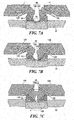
- Figs. 7A to 7C exemplarity show an assembling process of the molds.
- Figs. 8A and 8B show a clip that is formed by the manufacturing apparatus in detail.
- Fig. 8A is an enlarged view of a portion F in Fig. 7C
- Fig. 8B is a bottom view of the clip obtained by injection molding.
- the molds are all assembled together as shown in Fig. 7C by driving sequentially the sliders 104, 106, the first movable mold 100 and the second movable mold 102.
- a cavity 130 that follows an external shape of the clip 1 is formed.
- an injection path is formed in the cavity 130 through which a resin material for injection molding is injected. Then, by injecting a resin material through an injection apparatus, not shown, the clip 1 integrally having the head portion 2, the leg portion 4, the shank portion 6 and the flange portion 8 can be obtained.
- the second mold 54 and the third mold 56 form the continuous surface 132 at the boundary therebetween, and the second flange 12 is formed by the continuous surface 132 and the spacers 76 which face each other. Since a boundary line PL between the second mold 54 and the third mold 56 that form the continuous surface 132 is formed into a circular shape, an annular parting line is formed along the boundary line PL on the clip 1.
- an annular parting line PL1 is formed along the boundary line PL on the leg-portion-4-facing surface of the second flange 12.
- No other parting line is formed radially outwards of the parting line PL1 by setting the position, shape and dimension of the boundary line PL between the second mold 54 and the third mold 56.
- another parting line PL2 extending radially inwards is formed inwards of the annular parting line PL1 on the leg-portion-4-facing surface of the second flange 12.
- This parting line PL2 is formed along a boundary line between the first movable mold 100 and the second movable mold 102 of the second mold 54.
- the parting line PL1 is formed on the second flange 12 in a position lying a predetermined length x inwards from an outer circumferential edge of the second flange 12. Because of this, an annular sealing portion that surrounds the parting line PL1 is ensured over a predetermined range lying outwards of the parting line PL1 on the second flange 12. Namely, this predetermined distance x is set such that an annular sealing surface which abuts with an attachment-base member such as a door panel in a fluid-tight fashion is formed between the outer circumferential edge of the second flange 12 and the parting line PL1.
- Fig. 9 shows an application example of the clip.
- the above-described clip 1 is used in fixing a trim board 140 as an attachment-subject member to a door panel 150 as an attachment-base member. Namely, the top portion 2 of the clip 1 is firstly engaged with an attachment hole 142 of the trim board 140, and the head portion 2 is retained so that the trim board 140 is held by the head portion 2 and the first flange 10 therebetween.
- the top portion 2 of the clip 1 is firstly engaged with an attachment hole 142 of the trim board 140, and the head portion 2 is retained so that the trim board 140 is held by the head portion 2 and the first flange 10 therebetween.
- the attachment hole 142 is formed into a keyhole-like shape that is made up of a large hole having a diameter larger than that of the head portion 2 and a small hole that extends from the large hole and which has a diameter smaller than that of the head portion 2. Because of this, by inserting the head portion 2 of the clip 1 through the large hole and thereafter moving the shank portion 6 into the small hole, it is possible to cause the head portion 2 to engage with the attachment hole 142.
- the elastic locking portions 22 of the leg portion 4 are inserted into the attachment hole 152 while being contracted diametrically by the spaces 24, and are elastically restored after the spaces 24 have passed through.
- the diametrically-contracted portion 26 is positioned in the attachment hole 152, whereby the clip 1 is fixed to the door panel 150 such that the door panel 150 is held by the leg portion 4 and the second flange 12 therebetween.
- the lower surface (leg-portion-4-facing surface) of the second flange 12 elastically abuts with a front surface of the door panel 150.
- the lower surface of the second flange 12 constitutes a sealing surface to thereby be closely attached to the front surface of the door panel 150.
- a high sealing performance is realized on the inside and outside of the attachment hole 152 of the door panel 150. Namely, it is possible to prevent effectively the intrusion of water or air from a door panel 150 side to a trim board 140 side.
- the flange portion 8 including the first flange 10 and the second flange 12 is exemplified.
- a first flange 10 may be omitted.
- an attachment-subject member may be held between a head portion 2 and a second flange 12.
- the trim board is exemplified as the attachment-subject member
- the door panel is exemplified as the attachment-base member.
- the invention can be applied to other attachment-subject members and other attachment-base members by appropriately altering the shape and dimensions of the clip 1.
Landscapes
- Engineering & Computer Science (AREA)
- Mechanical Engineering (AREA)
- General Engineering & Computer Science (AREA)
- Manufacturing & Machinery (AREA)
- Moulds For Moulding Plastics Or The Like (AREA)
- Insertion Pins And Rivets (AREA)
Abstract
A clip 1 according to an aspect has a head portion 2 that is engaged with an attachment-subject member, a leg portion 4 that is inserted and locked in an attachment hole of an attachment-base member to which the attachment-subject member is to be fixed, a shank portion 6 that connects the head portion 2 with the leg portion 4, and a flange portion 8 that spreads obliquely outwards from the shank portion 6 towards the leg portion 4 and is closely attached to the attachment-base member so that an outer circumferential edge portion of a leg-portion-4-facing surface of the flange portion 8 surrounds the attachment hole when attached to the attachment-base member. The head portion 2, the leg portion 4, the shank portion 6 and the flange portion 8 are formed integrally from a resin material through an injection molding using a plurality of molds, an annular parting line PL1 that extends along a boundary surface between the molds is formed on the leg-portion-4-facing surface of the flange portion 8. On the other hand, no other parting line is formed radially outwards of the annular parting line PL1.


Description
- The present invention relates to a resin clip used to attach an attachment-subject member to an attachment-base member.
- Conventionally, resin clips are widely used in attaching an attachment-subject member to an attachment-base member, such as in attaching an automotive interior component such as a trim board to a door panel. Generally, such clips have a head portion which is engaged with an attachment-subject member, a leg portion that is locked on an attachment-base member, a shank portion that connects the head portion with the leg portion and a flange portion that expands outwards from the shank portion. In attaching the clip to the attachment-base member, the leg portion is inserted into an attachment hole of the attachment-base member, thereby fixing the clip to the attachment-base member while holding the periphery of the attachment hole by the leg portion and the flange portion. By press attaching the flange portion to the attachment-base member so as to surround the attachment hole, it is possible to prevent the intrusion of foreign matters through the attachment hole.
- Generally, such clips are mass-produced, and hence are formed from a resin material through an injection molding using dedicated molds (refer to
Patent Literature 1, for example). A plurality of molds which are so-called split molds are used as the dedicated molds. As a mold configuration, the molds abut with each other to form a cavity corresponding to a clip to be produced. The molds abut in a direction at right angles to an axis of the clip (in a radial direction of a flange portion to be produced) so that the clip can be removed from the molds after the injection molding is completed. -
- Patent Literature 1: JP-UM-S59-169419-A
- According to the above-described mold configuration, a parting line which is an uneven (projection) formed along a boundary between the molds is formed on a molded clip. Because of this, depending upon applications of the clip, this parting line causes a problem. For example, when the flow of water or air through an attachment hole of an attachment-base member needs to be prevented, a high sealing performance needs to be ensured by a flange portion. However, in the above-described mold configuration, the radial parting line is formed on a sealing surface of the flange portion. As a result, a void that establishes a communication between the outside and inside of the flange portion may be formed near the parting line. To ensure the high sealing performance, for example, a member such a packing may be separately provided between the attachment-base member and the flange portion. However, it is disadvantageous in production cost.
- The invention has been made in view of these situations, and an object thereof is to provide a technique that enables the sealing of an attachment hole of an attachment-base member with a high sealing performance by a single clip.
- With a view to solving the problem, according to an aspect of the invention, there is provided a clip including: a head portion that is engaged with an attachment-subject member; a leg portion that is inserted and locked in an attachment hole of an attachment-base member to which the attachment-subject member is to be fixed; a shank portion that connects the head portion with the leg portion; and a flange portion that expands obliquely outwards from the shank portion towards the leg portion. When attached to the attachment-base member, this clip is closely attached to the attachment-base member so that an outer circumferential edge portion of a leg-portion-facing surface of the flange portion surrounds the attachment hole. The head portion, the leg portion, the shank portion and the flange portion are formed integrally from a resin material through an injection molding using a plurality of molds, and an annular parting line that extends along a boundary surface between the molds is formed on the leg-portion-facing surface of the flange portion. On the other hand, no other parting line is formed radially outwards of the annular parting line.
- According to this aspect, although the annular parting line is formed on the surface of the flange portion facing the attachment-base member, no other parting line is formed radially outwards of the annular parting line. The clip of this aspect is obtained by using the molds that form the annular parting line on the flange portion. In the flange portion, since no radially-extending parting line is formed outwards of the annular parting line, it is possible to ensure an annular sealing surface having a high sealing performance outwards of the annular parting line.
- According to the invention, it is possible to provide the technique that enables the sealing of the attachment hole of the attachment-base member with the high sealing performance by the single clip.
-
-
Fig. 1 perspectively shows a clip according to a first embodiment. -
Figs. 2A to 2F show the clip in detail. -
Fig. 3 exemplarily shows a manufacturing apparatus of the clip. -
Figs. 4A and 4B show a first mold from above. -
Figs. 5A to 5C show a second mold. -
Figs. 6A and 6B show the molds in whole. -
Figs. 7A to 7C show an assembling process of the molds. -
Figs. 8A and 8B show a clip formed by the manufacturing apparatus in detail. -
Fig. 9 shows an application example of the clip. - A clip according to an embodiment has a head portion that is engaged with an attachment-subject member, a leg portion that is inserted and locked in an attachment hole of an attachment-base member to which the attachment-subject member is to be fixed, a shank portion that connects the head portion with the leg portion and a flange portion that expands obliquely outwards from the shank portion towards the leg portion, and when attached to the attachment-base member, this clip is closely attached to the attachment-base member so that an outer circumferential edge portion of a leg-portion-facing surface of the flange portion surrounds the attachment hole. The head portion, the leg portion, the shank portion and the flange portion are formed integrally from a resin material through an injection molding using a plurality of molds, and an annular parting line that extends along a boundary surface between the molds is formed on the leg-portion-facing surface of the flange portion. On the other hand, no other parting line is formed radially outwards of the annular parting line.
- This annular parting line lies at a predetermined distance radially inwards from an outer circumferential, edge of the flange portion. As a result, when the clip is attached to the attachment-base member, an annular sealing surface is formed between the outer circumferential edge of the flange portion and the parting line. The flange portion abuts with the attachment-base member in a fluid-tight fashion at the sealing surface. The "predetermined distance" for ensuring a sealing performance like this can be appropriately set through experiments or analyses and/or by taking into account the shapes and dimensions of the molds and the attachment hole. The parting line may preferably be formed further radially inwards of the flange portion than a limit value with which the sealing performance can be ensured.
- Another radially-extending parting line may be formed inwards of the annular parting line on the leg-portion-facing surface of the flange portion. Namely, depending on the shape of the leg portion, split molds need to be used. In this embodiment, the radial parting line is formed by a boundary line of the split molds. In other words, the split molds can be appropriately used as long as no parting line attributed to the split molds is formed on the sealing surface of the flange portion. By so doing, the aforesaid high sealing performance can be ensured.
- The clip can be manufactured by the following manufacturing apparatus. Namely, a clip manufacturing apparatus according to this embodiment forms the clip from a resin through injection molding and includes a first mold that forms a first surface of the clip corresponding to a head-portion-facing surface of the flange portion, a second mold that forms a second surface of the clip corresponding to the leg-portion-facing surface of the flange portion and a third mold that forms the leg portion. The second mold is configured as an integral mold including no divided portions and has an opening portion that is smaller than an outside diameter of the flange portion. A first-mold-facing surface of the second mold that lies outwards of the opening portion forms a predetermined range of the flange portion that extends inwards from the outer circumferential edge thereof.
- According to this embodiment, the "predetermined range" that extends inwards from the outer circumferential edge of the flange portion is formed by the first-mold-facing surface of the second mold that lies outwards of the opening portion. Since the second mold has no divided portions, no radial parting line is formed within the predetermined range. In the above-described manufacturing apparatus, it is possible to form the sealing surface having the high sealing performance within the predetermined range by assembling together the first mold, the second mold and the third mold and injecting a resin material into a cavity formed by those molds.
- The second mold and the third mold may form a continuous surface at a boundary therebetween by being assembled together so that a flange portion can be formed by the continuous surface and a surface of the first mold facing thereto, and a boundary line between the second mold and the third mold may be formed into an annular shape.
- According to this embodiment, an annular parting line is formed along the boundary line on the continuous surface between the second mold and the third mold. In other words, the second mold and the third mold form the annular parting line.
- Mating surfaces of the second mold and the third mold may be made obliquely relative to the continuous surface. The third mold may be made up of a plurality of dividable split molds, and the split molds may be assembled to the second mold so as to slide obliquely along the mating surfaces. By adopting this configuration, it is possible to realize the above-mentioned mold configuration specifically. By causing the third mold to slide obliquely, since the third mold can be assembled to the second mold through the sliding, the positioning of both the molds can be facilitated.
- Hereinafter, an embodiment of the invention will be described in detail by reference to the drawings. In the following description, a positional relationship in the drawings will be appropriately referred to.
Fig. 1 perspectively a clip according to a first embodiment.
Aclip 1 corresponds to the above-described clip, and is used for fixing a trim board (attachment-subject member) to a door panel (attachment-base member). In theclip 1, anannular head portion 2, a swellingleg portion 4, a pillar-shapedshank portion 6 and anannular flange portion 8 are formed integrally from a resin material through injection molding. Although there is imposed no specific limitation on the type of a resin material, a resin having a heat resistance may be preferably used such that wear or deformation hardly occurs. In this embodiment, a polyacetal (POM) resin is adopted. - The
flange portion 8 includes afirst flange 10 and asecond flange 12. Theseflange portions shank portion 6. As it will be specifically described later, in the locked state, theclip 1 holds a trim board by thehead portion 2 and thefirst flange portion 10, and holds a door panel by thesecond flange portion 12 and theleg portion 4, thereby fixing the trim board to the door panel. -
Figs. 2A to 2F show the clip in detail.Fig. 2A shows a front view of theclip 1,Fig. 2B shows a bottom view of theclip 1,Fig. 2C shows a sectional view of theclip 1 taken along the line A-A and seen in a direction indicated by arrows A shown atFig. 2A, Fig. 2D shows a sectional view of theclip 1 taken along the line B-B and seen in a direction indicated by arrows B-B shown atFig. 2A, Fig. 2E shows a sectional view of theclip 1 taken along the line C-C and seen in a direction indicated by arrows C shown atFig. 2A, and Fig. 2F shows a sectional view of theclip 1 taken along the line D-D and seen in a direction indicated by arrows D shown atFig. 2A . - The
head portion 2 has a flat circular disk shape and is provided concentrically at one end of theshank portion 6. As shown inFig. 2C , arecess portion 18 is formed in the center of thehead portion 2. Therecess portion 18 extends in an axial direction to a depth reaching theflange portion 8. By providing thisrecess portion 18, when forming theclip 1, theclip 1 can be stably supported in sprit molds, which will be described later, and can be prevented from being dislocated from the molds when the molds are separated. - As shown in
Figs. 2E, 2F , theleg portion 4 includes an pillar-shapedportion 20 that extends in an axis and that has a rectangular sectional shape and a pair ofelastic locking portions portion 20 so as to make up an outer circumference. Theelastic locking portion portion 20 form an S-shaped cross-sectional shape so as to define aspace 24 between each of theelastic locking portions portion 20, thereby providing elasticity when theclip 1 is locked on the attachment-base member. As shown inFig. 2C , the pillar-shapedportion 20 extends downwards from theflange portion 8, and has a tapered shape in which its cross section is gradually reduced towards a distal end thereof. - As shown in
Fig. 2A , theelastic locking portions flange portion 8 via a diametrically-contractedportion 26 that is contracted in a radial direction. Namely, eachelastic locking portion 22 gradually expands diametrically from the diametrically-contractedportion 26 and then gradually contracts diametrically to form adistal end 28. The shape of theleg portion 4 is not limited to the above-described shape, as long as theleg portion 4 can be to be inserted and locked in an attachment hole of the attachment-base member. - The
flange portion 8 includes thefirst flange 10 and thesecond flange 12. As shown inFig. 2D , thefirst flange portion 10 has a skirt shape that expands slightly obliquely upwards towards thehead portion 2. Thesecond flange 12 has a skirt shape that expands slightly downwards towards theshank portion 6. In this embodiment, as shown in the drawings, an outside diameter of thefirst flange portion 10 is made larger than an outside diameter of thesecond flange portion 12. However, a first flange portion and a second flange portion may be formed in a reverse relationship or formed to have the same size. - As shown in
Fig. 2B in particular, an annular parting line PL1 is formed on a lower surface (leg-portion-4-facing surface) of thesecond flange 12. The parting line PL1 is an uneven (projection) that extends along a boundary surface between the split molds in an injection molding. Another radially-extending parting line PL2 is also formed inwards of the parting line PL1. These parting lines are inevitably formed when a clip is formed using dividable sprit molds, and the details thereof will be described later. - Next, an apparatus and a method for manufacturing the clip will be described.
Fig. 3 exemplarily shows a manufacturing apparatus of the clip.Figs. 4A and 4B show a first mold from above.Fig. 4A shows a state in which left and right molds are opened, andFig. 4B shows a state in which the left and right molds are closed.Figs. 5A to 5C show a second mold.Fig. 5A shows a state in which the second mold is set in the first mold,Fig. 5B shows a plan view of the second mold, andFig. 5C shows a sectional view thereof taken along the line E-E and seen in a direction indicated by arrows E shown atFig. 5B .Figs. 6A and 6B show the molds in whole.Fig. 6A shows a state in which a third mold is opened, andFig. 6B shows a state in which the third mold is closed. - The
clip 1 can be manufactured through an injection molding using amanufacturing apparatus 50 shown inFig. 3 . Themanufacturing apparatus 50 includes afirst mold 52, asecond mold 54 and athird mold 56. Thefirst mold 52 is made up of horizontally-dividable split molds, and forms thehead portion 2, theshank portion 6 and part of theflange portion 8 that are shown inFigs. 1 and2A to 2F . Thesecond mold 54 is configured as an integral mold having no dividable portions and forms part of theflange portion 8 in cooperation with thefirst mold 52. Thethird mold 56 is made up of horizontally-dividable split molds, and forms part of theflange portion 8 in cooperation with thefirst mold 52, also forming theleg portion 4. - As shown in
Figs. 3 and4A, 4B , thefirst mold 52 includes abase portion 60 that is fixed to an apparatus main body, not shown, and a firstmovable mold 62 and a secondmovable mold 64 which make up a pair of split molds provided so as to hold thebase portion 60 therebetween from the left and right thereof. A circularannular groove 70 is provided in the center of thebase portion 60, and a circular boss-shaped supportingprojection 72 is erected in the center of theannular groove 70. Theannular groove 70 is a mold portion that forms a first surface (leg-portion-4-opposite surface) of thehead portion 2, and the supportingprojection 72 is a mold portion that forms therecess portion 18 in thehead portion 2. - The first
movable mold 62 includes a movablemain body 74 and aspacer 76. The movablemain body 74 has at an upper portion thereof a plate-shapedmold forming portion 78 that extends towards the supportingprojection 72, and thespacer 76 is joined to an upper surface of themold forming portion 78. In this embodiment, thespacer 76 has a rectangular plate shape and is fixed to themold forming portion 78 with a fastening member (screw), not shown. - The movable
main body portion 74 is driven in directions in which it moves towards and away from thebase portion 60, and as this occurs, a lower surface of themold forming portion 78 slides over an upper surface of thebase portion 60. A semi-circularannular groove 80 is provided on a lower surface of a distal end portion of themold forming portion 78 and makes up a mold portion that molds a second surface (leg-portion-4-facing surface) of thehead portion 2. A semi-circular annular groove 82 is also provided on an upper surface of the distal end portion of themold forming portion 78 and makes up a mold portion that molds a first surface (leg-portion-4-opposite surface) of thefirst flange 10. - A semi-circular
annular groove 84 is provided on a lower surface of a distal end portion of thespacer 76 and makes up a mold portion that molds a second surface (leg-portion-4-facing surface) of thefirst flange portion 10. A semi-circularannular groove 86 is formed on an upper surface of the distal end portion of thespacer 76 and makes up a mold portion that molds a first surface (leg-portion-4-opposite surface) of thesecond flange 12. The secondmovable mold 64 has the same configuration as that of the firstmovable mold 62. Hence, like reference numerals are given to like constituent portions to those of the firstmovable mold 62, and the description thereof is omitted. As shown inFig. 4B , when the firstmovable mold 62 and the secondmovable mold 64 are assembled together, the semi-circular annular grooves are combined together into a circular annular groove so as to mold annular portions. - As shown in
Figs. 3 and5A to 5C , thesecond mold 54 is constructed so as to slidably-support and lock thethird mold 56. As shown inFig. 5B , in thesecond mold 54, aguide hole 90 is provided so as to penetrate through a rectangular parallelepiped main body from an upper surface to a lower surface. Theguide hole 90 has a rectangular shape at an upper end portion thereof and is formed into a circular exposinghole 92 through which a central portion of thefirst mold 52 is exposed at a lower end portion thereof. Namely, the main body of thesecond mold 54 has a pair ofguide walls 94 and a pair ofguide walls 96, and theguide hole 90 is defined inside these guide walls. Theguide walls 94 constitute vertical surfaces relative to thespacers 76 of thefirst mold 52, and theguide walls 96form sloping surfaces 98 that slope down towards thespacers 76. Thesecond mold 54 is assembled to thefirst mold 52 by a driving mechanism, not shown, after thefirst mold 52 has been assembled. - Returning to
Fig. 3 , in thesecond mold 54, an inside diameter of a lower end opening portion of the exposinghole 92 is smaller than an outside diameter of thesecond flange 12, and a first-mold-52-facing surface (spacers-76-facing surface) outwards of the exposinghole 92 makes up a mold portion that forms an outer circumferential edge portion of thesecond flange 12. Namely, a central portion of a lower end surface of thesecond mold 54 constitutes amolding portion 99. Themolding portion 99 forms a predetermined range of thesecond flange 12 that extends inwards from an outer circumferential edge thereof. - As shown in
Figs. 3 and6A, 6B , thethird mold 56 includes a firstmovable mold 100 and a secondmovable mold 102 that make up a pair of split molds provided above thesecond mold 54. The firstmovable mold 100 and the secondmovable mold 102 are supported slidably by a pair ofsliders leg portion 4 on facing surfaces (mating surfaces) thereof. - The first
movable mold 100 has amolding portion 110 that forms theleg portion 4 at a lower half portion thereof. A lower end surface of the firstmovable mold 100 constitutes amolding portion 112 that forms the second surface (leg-portion-4-facing surface) of thesecond flange 12 in cooperation with thefirst mold 52. Similarly, the secondmovable mold 102 has amolding portion 110 that forms theleg portion 4 at a lower half portion thereof. A lower end face of the secondmovable mold 102 constitutes amolding portion 112 that forms the second surface (leg-portion-4-facing surface) of thesecond flange 12 in cooperation with thefirst mold 52. - The
sliders second mold 54.Guide rails 120 are provided on theslider 104 so as to extend obliquely relative to the upper surface of thefirst mold 52, and the firstmovable mold 100 is supported so as to move upwards or downwards along the guide rails 120. Similarly,guide rails 120 are also provided on theslider 106 so as to extend obliquely relative to the upper surface of thefirst mold 52, and the secondmovable mold 102 is supported so as to move upwards or downwards along the guide rails 120. The firstmovable mold 100 and the secondmovable mold 102 are driven along the respective guide rails by a driving device, not shown. - In the above-described configuration, by driving the
sliders second mold 54, the firstmovable mold 100 and the secondmovable mold 102, that is the mating surfaces thereof are moved towards each other (so as to form the third mold 56). At the same time, the firstmovable mold 100 is driven relative to theslider 104, and thesecond slider 102 is driven relative to theslider 106, whereby thesemovable molds surfaces 98 of thesecond mold 54, thereby being assembled to thesecond mold 54. When thethird mold 56 is assembled to thesecond mold 54 in this way, themolding portions 112 of thethird mold 56 and themolding portions 99 of thesecond mold 54 form a continuous surface at a boundary therebetween to thereby make up a molding portion that forms the second surface (leg-portion-4-facing surface) of thesecond flange 12. -
Figs. 7A to 7C exemplarity show an assembling process of the molds.Figs. 8A and 8B show a clip that is formed by the manufacturing apparatus in detail.Fig. 8A is an enlarged view of a portion F inFig. 7C , andFig. 8B is a bottom view of the clip obtained by injection molding. - As shown in
Figs. 7A and 7B , the molds are all assembled together as shown inFig. 7C by driving sequentially thesliders movable mold 100 and the secondmovable mold 102. In this way, acavity 130 that follows an external shape of theclip 1 is formed. Although not shown, an injection path is formed in thecavity 130 through which a resin material for injection molding is injected. Then, by injecting a resin material through an injection apparatus, not shown, theclip 1 integrally having thehead portion 2, theleg portion 4, theshank portion 6 and theflange portion 8 can be obtained. - As this occurs, as shown in
Fig. 8A , thesecond mold 54 and thethird mold 56 form thecontinuous surface 132 at the boundary therebetween, and thesecond flange 12 is formed by thecontinuous surface 132 and thespacers 76 which face each other. Since a boundary line PL between thesecond mold 54 and thethird mold 56 that form thecontinuous surface 132 is formed into a circular shape, an annular parting line is formed along the boundary line PL on theclip 1. - Namely, as shown in
Fig. 8B , an annular parting line PL1 is formed along the boundary line PL on the leg-portion-4-facing surface of thesecond flange 12. No other parting line is formed radially outwards of the parting line PL1 by setting the position, shape and dimension of the boundary line PL between thesecond mold 54 and thethird mold 56. On the other hand, another parting line PL2 extending radially inwards is formed inwards of the annular parting line PL1 on the leg-portion-4-facing surface of thesecond flange 12. This parting line PL2 is formed along a boundary line between the firstmovable mold 100 and the secondmovable mold 102 of thesecond mold 54. - The parting line PL1 is formed on the
second flange 12 in a position lying a predetermined length x inwards from an outer circumferential edge of thesecond flange 12. Because of this, an annular sealing portion that surrounds the parting line PL1 is ensured over a predetermined range lying outwards of the parting line PL1 on thesecond flange 12. Namely, this predetermined distance x is set such that an annular sealing surface which abuts with an attachment-base member such as a door panel in a fluid-tight fashion is formed between the outer circumferential edge of thesecond flange 12 and the parting line PL1. - Next, a specific application of the
clip 1 will be described.
Fig. 9 shows an application example of the clip.
For example, the above-describedclip 1 is used in fixing atrim board 140 as an attachment-subject member to adoor panel 150 as an attachment-base member. Namely, thetop portion 2 of theclip 1 is firstly engaged with anattachment hole 142 of thetrim board 140, and thehead portion 2 is retained so that thetrim board 140 is held by thehead portion 2 and thefirst flange 10 therebetween. For example, as shown inFig. 2 ofPatent Literature 1, theattachment hole 142 is formed into a keyhole-like shape that is made up of a large hole having a diameter larger than that of thehead portion 2 and a small hole that extends from the large hole and which has a diameter smaller than that of thehead portion 2. Because of this, by inserting thehead portion 2 of theclip 1 through the large hole and thereafter moving theshank portion 6 into the small hole, it is possible to cause thehead portion 2 to engage with theattachment hole 142. - When the
leg portion 4 of theclip 1 is pushed into anattachment hole 152 of thedoor panel 150 in this state, theelastic locking portions 22 of theleg portion 4 are inserted into theattachment hole 152 while being contracted diametrically by thespaces 24, and are elastically restored after thespaces 24 have passed through. As this occurs, the diametrically-contractedportion 26 is positioned in theattachment hole 152, whereby theclip 1 is fixed to thedoor panel 150 such that thedoor panel 150 is held by theleg portion 4 and thesecond flange 12 therebetween. Then, the lower surface (leg-portion-4-facing surface) of thesecond flange 12 elastically abuts with a front surface of thedoor panel 150. - As this occurs, since no other parting line is formed outwards of the annular parting line PL1 on the lower surface of the
second flange 12, the lower surface of thesecond flange 12 constitutes a sealing surface to thereby be closely attached to the front surface of thedoor panel 150. Thus, a high sealing performance is realized on the inside and outside of theattachment hole 152 of thedoor panel 150. Namely, it is possible to prevent effectively the intrusion of water or air from adoor panel 150 side to atrim board 140 side. - The invention is not limited to the above-described embodiment, and it is possible to make modifications such as various design changes to the embodiment based on the knowledge of the skilled person, embodiments with such modifications will also fall within the scope of the invention.
- In the above-described embodiment, as shown in
Fig. 1 , theflange portion 8 including thefirst flange 10 and thesecond flange 12 is exemplified. However, for example, afirst flange 10 may be omitted. In this case, an attachment-subject member may be held between ahead portion 2 and asecond flange 12. - In the embodiment, the trim board is exemplified as the attachment-subject member, and the door panel is exemplified as the attachment-base member. However, the invention can be applied to other attachment-subject members and other attachment-base members by appropriately altering the shape and dimensions of the
clip 1. - 1 Clip; 2 Head portion; 4 Leg portion; 6 Shank portion; 8 Flange portion; 10 First flange; 12 Second flange; 50 Manufacturing apparatus; 52 First mold; 54 Second mold; 56 Third mold; 60 Base portion; 62 First movable mold; 64 Second movable mold; 70 Annular groove; 72 Supporting projection; 74 Movable main body; 76 Spacer; 78 Mold forming portion; 80, 82, 84, 86 Annular groove; 90 Guide hole; 92 Exposing hole; 94, 96 Guide wall; 98 Sloping surface; 99 Molding portion; 100 First movable mold; 102 Second movable mold; 104, 106 Slider; 110, 112 Molding portion; 120 Guide rail; 130 Cavity; 140 Trim board; 142 Attachment hole; 150 Door panel; 152 Attachment hole; PL1, PL2 Parting line.
Claims (7)
- A clip manufacturing apparatus for forming a clip through injection molding of resin, the clip comprising:a head portion that is engaged with an attachment-subject member;a leg portion, that is inserted and locked in an attachment hole of an attachment-base member to which the attachment-subject member is to be fixed;a shank portion that connects the head portion with the leg portion; anda flange portion that spreads obliquely outwards from the shank portion towards the leg portion and closely attached to the attachment-base member so that an outer circumferential edge portion of a leg-portion-facing surface of the flange portion surrounds the attachment hole when attached to the attachment-base member, the clip manufacturing apparatus comprising:a first mold that forms a first surface side of the flange portion corresponding to a head-portion-facing surface of the flange portion;a second mold that forms a second surface side of the flange portion corresponding to the leg-portion-facing surface of the flange portion; anda third mold that forms the leg portion,wherein the second mold is configured as an integral mold having no dividable portion and has an opening portion that is smaller than an outside diameter of the flange portion, a first-mold-facing surface of the second mold forming a predetermined range of the flange portion that extends inwards from an outer circumferential edge thereof.
- The clip manufacturing apparatus of Claim 1,
wherein the second mold and the third mold form a continuous surface at a boundary therebetween by being assembled together,
wherein the flange portion is formed by the continuous surface and a surface of the first mold facing thereto, and
wherein a boundary line between the second mold and the third mold is formed into an annular shape. - The clip manufacturing apparatus of Claim 2,
wherein mating surfaces of the second mold and the third mold are made obliquely relative to the continuous surface, and
wherein the third mold is made up of a plurality of dividable split molds, the split molds being assembled to the second mold so as to slide obliquely along the mating surfaces. - A clip manufacturing method for forming a clip through injection molding of resin, the clip comprising:ahead portion that is engaged with an attachment-subject member;a leg portion that is inserted and locked in an attachment hole of an attachment-base member to which the attachment-subject member is to be fixed;a shank portion that connects the head portion with the leg portion; anda flange portion that spreads obliquely outwards from the shank portion towards the leg portion and closely attached to the attachment-base member so that an outer circumferential edge portion of a leg-portion-facing surface of the flange portion surrounds the attachment hole when attached to the attachment-base member, the clip manufacturing method comprising:assembling together a first mold that forms a first surface side of the flange portion corresponding to a head-portion-facing surface, a second mold configured as an integral mold having no dividable portion and configured to form a second surface side of the flange portion corresponding to the leg-portion-facing surface and a third mold that forms the leg portion, the second mold having an opening portion that is smaller than an outside diameter of the flange portion, a first-mold-facing surface of the second mold that lies outwards of the opening portion forming a predetermined range of the flange portion that extends inwards from an outer circumferential edge thereof; andinjecting a resin material into a cavity that is defined by the first mold, the second mold and the third mold.
- A clip comprising:a head portion that is engaged with an attachment-subject member;a leg portion that is inserted and locked in an attachment hole of an attachment-base member to which the attachment-subject member is to be fixed;a shank portion that connects the head portion with the leg portion; anda flange portion that spreads obliquely outwards from the shank portion towards the leg portion and closely attached to the attachment-base member so that an outer circumferential edge portion of a leg-portion-facing surface of the flange portion surrounds the attachment hole when attached to the attachment-base member,wherein the head portion, the leg portion, the shank portion and the flange portion are formed integrally from a resin material through an injection molding using a plurality of molds, an annular parting line that extends along a boundary surface between the molds is formed on the leg-portion-facing surface of the flange portion, and no other parting line is formed radially outwards of the annular parting line.
- The clip of Claim 5,
wherein, when the clip is attached to the attachment-base member, the annular parting line lies at a predetermined distance radially inwards from an outer circumferential edge of the flange portion so that an annular sealing surface is formed between the outer circumferential edge of the flange portion and the parting line so as to abut with the attachment-base member in a fluid-tight fashion. - The clip of Claim 6,
wherein another radially-extending parting line is formed inwards of the annular parting line on the leg-portion-facing surface of the flange portion.
Applications Claiming Priority (2)
| Application Number | Priority Date | Filing Date | Title |
|---|---|---|---|
| JP2010118531 | 2010-05-24 | ||
| PCT/JP2011/002744 WO2011148589A1 (en) | 2010-05-24 | 2011-05-17 | Clip, method for producing clip, and device for producing clip |
Publications (1)
| Publication Number | Publication Date |
|---|---|
| EP2578375A1 true EP2578375A1 (en) | 2013-04-10 |
Family
ID=45003590
Family Applications (1)
| Application Number | Title | Priority Date | Filing Date |
|---|---|---|---|
| EP11786293.8A Withdrawn EP2578375A1 (en) | 2010-05-24 | 2011-05-17 | Clip, method for producing clip, and device for producing clip |
Country Status (5)
| Country | Link |
|---|---|
| US (1) | US20130129450A1 (en) |
| EP (1) | EP2578375A1 (en) |
| JP (1) | JP5511948B2 (en) |
| CN (1) | CN102905870B (en) |
| WO (1) | WO2011148589A1 (en) |
Families Citing this family (9)
| Publication number | Priority date | Publication date | Assignee | Title |
|---|---|---|---|---|
| DE112013003061T5 (en) * | 2012-09-13 | 2015-03-12 | Illinois Tool Works Inc. | The fastening clip assembly |
| WO2014099444A1 (en) | 2012-12-19 | 2014-06-26 | Illinois Tool Works Inc. | Push through retainer connection with integrated hinging seal |
| JP6285681B2 (en) * | 2013-10-01 | 2018-02-28 | 株式会社パイオラックス | Locking tool to mounting hole |
| FR3020099B1 (en) * | 2014-04-16 | 2017-08-18 | Illinois Tool Works | CLAMP FOR ATTACHING A PANEL TO A SUPPORT, METHOD FOR CARRYING OUT THE SAME, AND AUTOMOTIVE EQUIPMENT |
| JP2017210966A (en) * | 2014-08-28 | 2017-11-30 | 株式会社パイオラックス | Fastener |
| JP6463165B2 (en) * | 2015-02-19 | 2019-01-30 | 株式会社パイオラックス | Locking tool to mounting hole |
| US9939003B2 (en) * | 2015-06-25 | 2018-04-10 | Nifco America Corp. | Clip |
| JP6436460B2 (en) * | 2015-07-27 | 2018-12-12 | 矢崎総業株式会社 | Mold and molding method |
| CN109130017B (en) * | 2018-08-16 | 2024-05-03 | 深圳市时光电子有限公司 | Mould for umbrella valve, forming equipment and mould opening method thereof |
Family Cites Families (8)
| Publication number | Priority date | Publication date | Assignee | Title |
|---|---|---|---|---|
| JP3342191B2 (en) * | 1994-08-01 | 2002-11-05 | 株式会社ニフコ | Stop |
| CA2416345C (en) * | 2000-07-17 | 2010-09-07 | Decoma Exterior Trim Inc. | Dual durometer clip |
| JP4252827B2 (en) * | 2003-03-18 | 2009-04-08 | 株式会社パイオラックス | Plastic clip |
| JP4448345B2 (en) * | 2004-02-25 | 2010-04-07 | 紀伊産業株式会社 | Mold for molding and manufacturing method of synthetic resin product using the same |
| JP2006300169A (en) * | 2005-04-19 | 2006-11-02 | Daiwa Kasei Ind Co Ltd | Clip and molding method of clip |
| JP5226962B2 (en) * | 2007-03-01 | 2013-07-03 | 矢崎総業株式会社 | Mold apparatus and molding apparatus equipped with the mold apparatus |
| CN101566184B (en) * | 2008-04-25 | 2014-07-09 | 百乐仕株式会社 | Clamp |
| JP5342817B2 (en) * | 2008-06-26 | 2013-11-13 | 矢崎総業株式会社 | Mold device and module for electrical connection |
-
2011
- 2011-05-17 EP EP11786293.8A patent/EP2578375A1/en not_active Withdrawn
- 2011-05-17 JP JP2012517120A patent/JP5511948B2/en active Active
- 2011-05-17 US US13/699,401 patent/US20130129450A1/en not_active Abandoned
- 2011-05-17 CN CN201180025626.2A patent/CN102905870B/en not_active Expired - Fee Related
- 2011-05-17 WO PCT/JP2011/002744 patent/WO2011148589A1/en active Application Filing
Non-Patent Citations (1)
| Title |
|---|
| See references of WO2011148589A1 * |
Also Published As
| Publication number | Publication date |
|---|---|
| WO2011148589A1 (en) | 2011-12-01 |
| CN102905870B (en) | 2014-12-31 |
| CN102905870A (en) | 2013-01-30 |
| US20130129450A1 (en) | 2013-05-23 |
| JPWO2011148589A1 (en) | 2013-07-25 |
| JP5511948B2 (en) | 2014-06-04 |
Similar Documents
| Publication | Publication Date | Title |
|---|---|---|
| EP2578375A1 (en) | Clip, method for producing clip, and device for producing clip | |
| US4989302A (en) | Method for manufacturing piezoelectric buzzer | |
| US11298858B2 (en) | Method for manufacturing sealing device, and sealing device | |
| EP3281760B1 (en) | Manufacturing method for a gasket | |
| JP2004291901A (en) | Weather strip | |
| JP5084641B2 (en) | clip | |
| JP6161885B2 (en) | Syringe | |
| JP2020015211A (en) | Undercut treatment mechanism and molding die | |
| JP2006205511A (en) | Filter molding mold | |
| JP2001304207A (en) | Fastening structure | |
| CN211303091U (en) | Micro-channel device | |
| CN210996332U (en) | Mould and joint | |
| JP6667009B2 (en) | Hook-and-loop fastener | |
| US11933337B2 (en) | Clip and clip attaching structure | |
| US10611069B2 (en) | Injection-molding method for mesh filter, injection-molding mold, and mesh filter | |
| JP7530599B2 (en) | Pipe joint and method for manufacturing the same | |
| CN110509501B (en) | Opposite-plug type sliding side concave die mechanism and control method | |
| JP2006212943A (en) | Method for molding holder and holder | |
| JP6288185B2 (en) | Sealing device | |
| CN115816774A (en) | Telescopic core mechanism | |
| US20190190114A1 (en) | Polarizer assembly | |
| JP2013078934A (en) | Molding | |
| JP2012217467A (en) | Syringe | |
| JPH02289202A (en) | Fastener |
Legal Events
| Date | Code | Title | Description |
|---|---|---|---|
| PUAI | Public reference made under article 153(3) epc to a published international application that has entered the european phase |
Free format text: ORIGINAL CODE: 0009012 |
|
| 17P | Request for examination filed |
Effective date: 20121126 |
|
| AK | Designated contracting states |
Kind code of ref document: A1 Designated state(s): AL AT BE BG CH CY CZ DE DK EE ES FI FR GB GR HR HU IE IS IT LI LT LU LV MC MK MT NL NO PL PT RO RS SE SI SK SM TR |
|
| DAX | Request for extension of the european patent (deleted) | ||
| STAA | Information on the status of an ep patent application or granted ep patent |
Free format text: STATUS: THE APPLICATION HAS BEEN WITHDRAWN |
|
| 18W | Application withdrawn |
Effective date: 20150330 |