EP4197699A1 - Broche de montage intégrée, outil d'installation destiné au montage d'un insert fileté métallique et procédé d'installation - Google Patents
Broche de montage intégrée, outil d'installation destiné au montage d'un insert fileté métallique et procédé d'installation Download PDFInfo
- Publication number
- EP4197699A1 EP4197699A1 EP21214530.4A EP21214530A EP4197699A1 EP 4197699 A1 EP4197699 A1 EP 4197699A1 EP 21214530 A EP21214530 A EP 21214530A EP 4197699 A1 EP4197699 A1 EP 4197699A1
- Authority
- EP
- European Patent Office
- Prior art keywords
- installation
- spindle
- axial
- thread insert
- wire thread
- Prior art date
- Legal status (The legal status is an assumption and is not a legal conclusion. Google has not performed a legal analysis and makes no representation as to the accuracy of the status listed.)
- Pending
Links
Images


Classifications
-
- B—PERFORMING OPERATIONS; TRANSPORTING
- B25—HAND TOOLS; PORTABLE POWER-DRIVEN TOOLS; MANIPULATORS
- B25B—TOOLS OR BENCH DEVICES NOT OTHERWISE PROVIDED FOR, FOR FASTENING, CONNECTING, DISENGAGING OR HOLDING
- B25B27/00—Hand tools, specially adapted for fitting together or separating parts or objects whether or not involving some deformation, not otherwise provided for
- B25B27/14—Hand tools, specially adapted for fitting together or separating parts or objects whether or not involving some deformation, not otherwise provided for for assembling objects other than by press fit or detaching same
- B25B27/143—Hand tools, specially adapted for fitting together or separating parts or objects whether or not involving some deformation, not otherwise provided for for assembling objects other than by press fit or detaching same for installing wire thread inserts or tubular threaded inserts
Definitions
- the present invention relates to an integrally formed installation mandrel adapted to a wire thread insert, a retrofit kit for an installation tool with a plurality of such installation mandrels, an installation tool consisting of a drive module and an integrally formed installation mandrel and an installation method of a wire thread insert with a bendable, non-removable driving pin using the above mentioned installation tool.
- the installation mandrel used to install the wire thread insert in the threaded hole depends on the design of the wire thread insert to be installed. This is because the various constructions of wire thread inserts have, for example, a radially inwardly projecting, straight installation spigot which is broken out of the construction of the wire thread insert after installation.
- Another design is to provide the wire thread insert with a notch located radially inward. A corresponding driver engages in this notch in order to screw the wire thread insert into the internal thread. This design does not require the removal of a mounting stud after the wire thread insert is installed.
- a further constructive alternative of a wire thread insert has a radially inwardly bent installation spigot with or without a notch. After installation is complete, this mounting pin is bent back radially outwards into the internal thread of the threaded hole.
- DE 699 03 965 T2 describes an installation mandrel with a slot running parallel to the diameter of the installation mandrel for receiving an installation spigot of the wire thread insert. Due to the arrangement of the slot at the functional end of the built-in spindle, the axial face of the built-in spindle is divided into two axial extensions at the functional end. These two opposite axial extensions each have beveled areas. The beveled area of the one axial extension is arranged inclined radially outwards. It makes it easier to snap in the radially inwardly bent mounting pin of the wire thread insert.
- the second axial extension of the installation mandrel has an inclined plane inclined radially inwardly from the second axial extension toward the spigot receiving gap.
- This inclined plane has the function of facilitating release of the installation pin from the central gap at the working end of the installation mandrel when the installation mandrel is to be removed from the wire thread insert after installation of the wire thread insert is complete. Due to its central gap at the functional end, this construction of the installation spindle is therefore used to use an installation pin projecting radially inward for installation, but not to change it after installation.
- the wire thread insert to be installed also has a straight, radially inwardly projecting installation spigot.
- the spindle or a threaded bolt has a radially oriented axial undercut on the axial face of the functional end of the spindle.
- the installation spigot catches on this axial undercut.
- the installation spindle and wire thread insert thus form a non-rotatable connection so that the wire thread insert can be screwed into the threaded hole.
- Even with a reverse rotation of the threaded spindle or the threaded bolt the mounting pin is not changed. Only reverse rotation causes the axial undercut and mounting spigot to disengage.
- U.S. 3,348,293 discloses a mounting mandrel for a wire thread insert having a radially inwardly curved arcuate mounting post.
- the built-in spigot has a predetermined breaking point so that after the wire thread insert has been installed in an internal thread, the built-in spigot can be broken out of the wire thread insert.
- the installation spindle has a driving shoulder at its functional end, which engages in the bend of the wire thread insert opposite the apex between the installation pin and the rest of the wire thread insert. This creates a non-rotatable connection between the installation spindle and the wire thread insert, so that the wire thread insert can be screwed into the internal thread. If the installation spindle is turned in the opposite direction to the screwing-in direction, the installation spindle is unscrewed from the installed wire thread insert. As soon as this has been done, the installation pin connected via the predetermined breaking point can be separated.
- EP 3 212 361 B1 discloses an installation mandrel for a wire thread insert with a retractable installation stem. On a radial inner side, this installation spigot which can be bent back has an installation notch, in which the installation spindle engages for screwing the wire thread insert into the internal thread of the threaded bore.
- the installation spindle has an axial extension on the axial end face of the installation end. This axial extension uses a length-reduced thread along a circumferential extent to guide the wire thread insert. In the installation direction at the start of the length-reduced thread turn, a driver edge is provided, which engages in the notch of the wire thread insert arranged radially on the inside.
- the cam edge extends parallel to the longitudinal axis of the installation mandrel to ensure reliable engagement with the cam notch of the wire thread insert.
- a bending shoulder designed in the shape of a circular arc.
- the European Patent 2 637 825 B1 discloses a wire thread insert for installation in a receiving thread of a component.
- This wire thread insert has a driver pin projecting over a bending area into an interior of the walls of the wire thread insert.
- the tang is inseparably connected to the helix of the wire thread insert.
- the driver pin which is bent radially inward, is characterized in that it can be bent back into a receiving thread of a threaded bore using a suitable tool.
- the above-mentioned European patent describes an installation tool which is specially designed on a working end of the installation mandrel.
- two axial extensions arranged separately from one another protrude from the axial end face.
- a receiving gap is formed between these axial extensions, in which a radially movable compression blade is arranged.
- the two axial extensions and the interposed movable compression blade form a length-reduced thread turn for guiding a part of the wire thread insert through their radial outer sides.
- the second axial extension which is arranged at the end of the reduced-length thread as viewed in the direction of rotation, serves as a reverse bending shoulder for bending back the driver pin into the receiving thread of the threaded hole.
- the compression blade arranged between the two axial extensions is moved in the radial direction in such a way that it blocks the length-reduced thread turn in a radially outer position in order to be able to compress the driver pin during bending back.
- the constructively complex installation spindle for installing the wire thread insert with bendable installation spigot must be controlled in a suitable manner in order to be able to use all the constructive features during the installation of the wire thread insert.
- an integrally formed installation spindle according to independent patent claim 1 a retrofit kit for an installation tool with drive module and detachable installation spindle with at least two integrally formed installation spindles according to independent patent claim 9, an installation tool with the integrally formed installation spindle according to independent patent claim 10 and by an installation method of a wire thread insert using the installation tool according to the invention according to the independent patent claim 11.
- the present invention discloses an integrally formed installation spindle adapted to a wire thread insert, which has a cylindrical helix with a plurality of helically wound windings of a wire, in which a first winding comprises a preferably arcuate driving pin without a driving notch, which protrudes over a bending region into an interior of the helix which the wire thread insert can be screwed into a threaded hole of a component in a screwing-in direction.
- the installation mandrel of the present invention has the following features: a drive and holding end for rotating and holding the installation mandrel in an installation tool, and an operational end for installing the wire thread insert into a threaded bore of a component from an axial face of the installation spindle at the functional end, an axial extension protrudes in the direction of a longitudinal axis of the installation spindle, which is delimited along a circumferential extension of the installation spindle by an arcuate radial outside at an angle of rotation ⁇ from a range of 30 ° ⁇ ⁇ 180 °, based on the screwing-in direction the axial extension, starting at a front end of the arcuate radial outside, has a run-on slope that extends in the axial direction of the installation spindle and increases on the axial extension, and in relation to the screwing-in direction, the axial extension falls at a rear end of the arcuate radial outside in a axial reverse bending surface axially, which is arranged
- the integral installation mandrel according to the invention is constructed as a robust one-piece installation mandrel which can be used interchangeably in an installation tool for wire thread inserts. Compared to known installation mandrels for wire thread inserts with bendable installation spigot, the present installation mandrel is more robust in use due to the one-piece design and is therefore characterized by a higher stability and service life compared to multi-part installation mandrels.
- the central element of the installation spindle is an axial extension at a functional end of the installation spindle, i.e. the end onto which the wire thread insert to be installed with a bendable installation pin is screwed or plugged, which is arranged on the axial end face of the installation spindle at its functional end.
- This preferably only one axial extension is designed in its shape in such a way that it forms a non-rotatable connection with the wire thread insert with the built-in pin that can be bent back after it has been screwed on.
- the bendable built-in spigot snaps over the axial extension until, after further rotation of the built-in spindle, it snaps onto it in a rotationally fixed manner.
- This non-rotatable, positive connection ensures that the wire thread insert can be rotated or screwed into the internal thread of the threaded hole in a component without any problems.
- the strip-shaped ramp forms the preparation for a resilient snap connection between the radially inwardly bent, bendable mounting pin and the axial extension on the axial base of the mounting spindle.
- the installation spindle can be removed from the wire thread insert by turning it in the opposite direction to the installation direction of rotation.
- this reverse rotation of the installation mandrel simultaneously deflects the reversible installation post back into the internal threads of the threaded bore. Since he prefers If the axial extension ends in a reverse bending surface at the end opposite the ramp, this reverse bending surface presses the mounting pin when the mounting spindle is turned back radially outwards in the direction of the internal thread of the threaded bore.
- the preferably only one axial extension on the axial end face of the installation spindle represents a multifunctional, axial extension. This multifunctional extension supports the installation process of the wire thread insert in the threaded hole through its strip surface-like ramp and also ends the installation process by bending the installation pin back into the internal thread of the Threaded hole using the reverse bending surface.
- the axial extension has at least one thread that is reduced in length in the circumferential direction.
- the axial extension protrudes from the axial end face at the functional end of the installation spindle.
- the radial outside of the axial extension extends in the circumferential direction of the installation spindle.
- the thread on the functional end of the installation spindle preferably also continues on the radial outside in the form of a preferably reduced-length thread in the circumferential direction of the axial extension.
- a preferably reduced-length thread in the circumferential direction of the axial extension.
- one or two threads on its arcuate radial outside is also preferred to provide more than two reduced length threads should they aid in the installation and/or removal of the installation mandrel from an installed retractable installation stem wire threaded insert.
- the axial extension at the functional end of the installation spindle individually protrudes axially on the axial end face.
- the axial extension occupies less than 40% of the axial end face at the functional end.
- this preferably occupies an area of less than 50% of the axial end face at the functional end of the built-in spindle.
- This surface area which can also be reduced to 25-35%, is sufficient to realize the non-rotatable mounting bracket for the wire thread insert on the axial extension and to effectively and sufficiently bend back the bendable mounting pin into the internal thread of the threaded hole when the mounting spindle is uninstalled.
- the axial extension has two length-reduced thread turns on the radial outside, which are designed differently in at least one of the following sizes: circumferential length, core diameter and pitch.
- two reduced-length threads are preferably provided on the radial outside running in the circumferential direction. While the wire thread insert is being screwed onto the functional end of the installation spindle, the reduced-length threads serve to guide the wire helix of the wire thread insert. As soon as the bendable built-in pin is held in a rotationally fixed manner on the axial extension, this hold is also supported by the course of the wire helix of the wire thread insert in at least one of the length-reduced thread turns.
- a specific shape of the length-reduced threads ensures that the bendable mounting pin is effectively bent back into the internal thread of the threaded hole.
- the core diameter and/or the pitch of the two length-reduced thread turns are designed differently compared to the remaining thread of the installation spindle.
- the core diameter and/or the pitch of only one length-reduced thread turn are designed differently in comparison to the remaining thread of the installation spindle.
- a larger core diameter of only the axially outer reduced-length thread or both reduced-length threads supports a bending back of the built-in pin that can be bent back into the internal thread of the threaded bore.
- a pitch of one or both reduced-length threads that is greater than the rest of the thread of the installation spindle in order to support bending back of the installation pin that can be bent back into the internal thread of the threaded bore.
- the axially outer reduced-length thread preferably has a larger core diameter and/or a greater pitch in comparison to the adjacent reduced-length thread.
- the axial extension has an axial web in the axial direction between the axial end face of the functional end and the front end of the ramp as a driving shoulder, which is adapted to hold a wire thread insert in a rotationally fixed manner when it is screwed into a threaded bore.
- the axial extension is preferably unscrewed from an interior of the wire thread insert in the axial direction. If the axial extension protrudes only slightly beyond the inside of the wire thread insert, the bendable mounting pin slides along the ramp on the axial extension and the screwing of the mounting spindle into the wire thread insert or the spinning of the wire thread insert onto the functional end of the mounting spindle continues. As soon as the axial extension preferably protrudes far enough out of the inside of the wire thread insert, the built-in pin can no longer run onto the ramp and slide there over the axial extension.
- the built-in pin that can be bent back remains hanging on the preferred driving shoulder or the axial web provided for this purpose and in this way forms a non-rotatable connection between the functional end of the built-in spindle and the screwed-on wire thread insert.
- the driver shoulder or the axial web which is arranged between the beginning of the ramp and the adjacent axial end face of the installation spindle, form a positive connection with the installation pin, which prevents further screwing of the wire thread insert onto the functional end of the installation spindle.
- the axial reverse bending surface encloses an angle ⁇ in the range of 65° ⁇ 90° with the adjoining axial end face of the functional end.
- the axial reverse bending surface is provided for a preferred bending back of the mounting pin into the internal thread of the threaded bore.
- the axial reverse bending surface forms an angle of less than 90° compared to the axial end face of the installation spindle.
- the bendable mounting pin is preferably held at an acute angle between the bend-back surface and the axial end face of the mounting spindle, while it is bent in the opposite direction to turning the wire thread insert into the internal thread of the threaded bore.
- the present invention also includes a retrofit kit for an installation tool for a wire thread insert with a drive module that can be releasably connected to one another and an installation spindle, which, as exchangeable installation spindles, has at least two integrally designed installation spindles according to one of having the embodiments described above, which differ in a construction and/or dimension of the installation spindle.
- the present invention includes an installation tool, in particular a manual installation tool or an installation machine, a wire thread insert with a drive module that can be releasably connected to one another and an integrally formed installation spindle according to one of the embodiments described above.
- the integral installation mandrel described above, with its various structural configurations, is used within an installation tool for installing wire thread inserts.
- installation tools include, on the one hand, manually used installation tools.
- Such installation tools are arranged manually by a worker, oriented towards the thread opening and then the worker triggers the screwing of the wire thread insert into the threaded hole by actuating corresponding switching elements.
- the integrally formed installation spindle is used in an installation machine for wire thread inserts.
- Such built-in machines work automatically. This means that the wire thread insert is arranged on the installation spindle via a mechanical feed. The component with the threaded opening is arranged in the installation direction below the installation tool via another machine feed.
- the present invention also discloses an installation method of a wire thread insert with a bendable, non-removable driving pin without a driving notch with the aid of an installation tool preferred according to the invention in a receiving thread of a component, which has the following steps: Spindle or push the wire thread insert onto the functional end of the integrally formed installation spindle of the installation tool in such a way that the driver pin couples positively to the axial extension of the installation spindle and the wire thread insert non-rotatably connects to the installation spindle, screwing the wire thread insert into the receiving thread by rotating the installation spindle in a first direction of rotation, bending back the driver pin into the receiving thread by rotating the installation spindle in a second, the first opposite direction of rotation, wherein the axial reverse bending surface of the axial extension deforms the tang, and spinning or removing the installation mandrel from the wire thread insert with the tang bent back.
- the inventive installation method for the wire thread insert with retractable installation stem using the integrally formed installation mandrel builds on the installation method according to FIG European Patent 3 212 361 B1 on.
- only the integrally formed installation spindle is used to screw in the wire thread insert and to bend back the installation pin into the internal thread of the threaded bore.
- the entire functionality of the integrally formed built-in spindle is reduced to the interaction between the preferably only one axial extension on the axial end face of the functional end of the built-in spindle. Because the axial extension is used on the one hand to produce a non-rotatable positive connection between the wire thread insert and the installation spindle.
- the installation method takes place radial bending back of the driving pin through a bending shoulder or a second threaded area with an enlarged core diameter compared to a first threaded area at the functional end of the installation spindle.
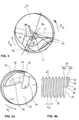
- FIG 1 12 shows a preferred embodiment of an integrally formed installation mandrel 1.
- Such installation mandrels 1 are used in an installation tool W, with which a wire-threaded insert D is installed in a threaded bore of a component.
- a preferred hand held installation tool W is shown figure 11 .
- It comprises a drive unit 3 for rotating the preferred installation spindle 1.
- the drive unit 3 is preferably connected to the drive and holding end 10 of the installation spindle 1 in a rotationally fixed manner. Via an actuating switch 5, according to a preferred Configuration of the installation tool W, the drive unit 3 started or stopped.
- a depth stop 7 preferably determines in a known manner how deep a wire thread insert D with a built-in pin Z that can be bent back can be screwed or dragged into a threaded hole of a component by turning the built-in spindle 1 at most.
- integrally formed installation spindle 1 in an installation machine. This installs a wire thread insert D in a threaded hole in a component using automated work processes.
- the inventively preferred integrally designed installation spindle 1 consists of one piece. This means that there are no moving or immovable parts attached to the installation spindle 1, such as a pivotable or rotatable installation or compression blade.
- the installation spindle 1 is adapted to install a wire thread insert D with an installation pin Z that can be bent back in a threaded bore of a component.
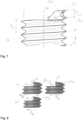
- the wire thread insert D is exemplary in Figure 2b shown. It comprises a cylindrical helix with a plurality of helically wound windings of a wire, in which a first winding has a preferably arcuate driver pin Z without a driver notch, which protrudes over a bending region into the interior of the helix.
- Such wire thread inserts are in EP 2 637 825 B1 1 is explained and illustrated in accordance with various preferred embodiments, which is incorporated herein by reference for a technical understanding of the wire thread insert.
- the installation mandrel 1 has a drive and support end 10 for driving the installation mandrel 1 with a drive module of an installation tool (see Fig 11 ) connect to.
- the drive and holding end 10 is held in the drive module in a detachable manner, preferably via a polygonal end and/or other known coupling structures.
- Such drive and holding ends 10 for holding and transmitting torque to the installation spindle 1 are known in the prior art.
- a functional end 20 of the installation spindle 1 is provided axially opposite the drive and holding end 10 .
- the functional end 20 of the installation spindle 1 preferably has a spindle area 22, ie an external thread 26 rotating to the right or left.
- the spindle area 22 is used to screw on the wire thread insert D in the direction of the drive end 10.
- the wire thread insert D is screwed onto the functional end 20 until the bendable mounting pin Z is held or anchored in a rotationally fixed manner on an axial extension 30 of an axial end face 24 of the mounting spindle 1.
- rotationally fixed means that the installation pin Z and the axial extension 30 form a positive connection, so that the installation spindle 10 rotates the wire thread insert D as well.
- FIG. 1 shows a perspective view of the installation spindle 1
- Figure 2A a lateral sectional view of the installation spindle 1 is reproduced. It can be seen that the axial extension 30 protrudes from the axial end face 24 of the installation spindle 1 in the direction of the longitudinal axis of the installation spindle 1 and thus axially.
- the installation spindle 1 is provided integrally, ie as a whole and firmly connected.
- the installation spindle 1 is made with the axial extension 30 in one piece.
- the axial extension 30 (see below) is subject to wear due to the installation operations of wire thread inserts D, while the rest of the installation mandrel 1 wears less. It is therefore also preferred to manufacture the axial extension 30 separately and then to connect it firmly and integrally to the rest of the installation spindle 1. Cohesive connection methods such as welding and gluing are preferred for this purpose.
- the wire thread insert D would be slipped onto the functional end 20 without a thread in the axial direction until the built-in spigot Z, which can be bent back, has been anchored in a rotationally fixed manner on the axial extension 30 . Thereafter, the wire thread insert D, which is held non-rotatably at the functional end 20, is screwed into the threaded bore of the component, preferably in the same way as is described below.
- the external thread 26 extends on the spindle area 22 of the functional end 20 and on a radial outside 32 of the axial extension 30. Since the axial extension 30 covers only a fraction of the axial end face 24 of the installation spindle, preferably a proportion of less than 50% of the axial end face 24, the external thread 26 continues as at least one length-reduced thread 34 on the radial outside of the axial extension 30--that is, in the circumferential extension of the installation spindle.
- the axial extension 30 has a height relative to the axial end face 24 of the installation spindle 1, so that two or more length-reduced thread turns 34 are arranged on the radial outside 32 of the axial extension 30 and running in the circumferential direction of the installation spindle 1.
- a geometric design of the preferably at least two length-reduced thread turns 34 is discussed in more detail below.
- FIGS 3, 4a and 5 show views of preferred embodiments of the axial face 24 of the installation spindle 1.
- the axial extension 30 is preferably eccentric with respect the end face 24 arranged and protrudes from this.
- only one axial extension 30 is preferably provided on the axial end face 24 in order to screw the wire thread insert D into the threaded bore and to bend the mounting pin back into the internal thread.
- the preferred axial extension 30 occupies an area of less than 50%, preferably in the range of 30 to 40%, of the axial end face 24 .
- the axial extension 30 preferably consists at least of the radial outer side 32 in the form of a wall viewed in the circumferential direction of the functional end 20 with a course and an extent in the form of a circular arc.
- the course of a circular arc an approximation by a curvilinear course is used.
- the axial extension 30 has a preferred radial width B of 0.1 R ⁇ B ⁇ 0.8 R, which is variable in the circumferential direction, with R describing the radius of the functional end 20 .
- B is not necessarily constant along the radial outside 32, so that the axial extension 30 can have an irregular shape with an arcuate radial side in an axial plan view.
- the axial extension 30 has a ramp 36 on a side facing away from the drive and holding end 10 .
- the ramp 36 preferably rises continuously in an angular range of 5° ⁇ ⁇ ⁇ 40° up to the axially highest point or axially furthest point from the holding end 10 of the axial extension 30.
- the bevel 36 consists of a strip surface which runs onto the axial extension 30 in an inclined axial direction. It is also preferred to provide the ramp 36 as a web or bead-like thickening that runs onto the axial extension 30 .
- the different preferred configurations of the ramp 36 allow the radially inwardly bent mounting pin Z of the wire thread insert D to run onto the axial extension 30 while the wire thread insert D is being screwed onto the functional end 20.
- the wire thread insert D is preferably held on a driver shoulder 38 and rotated with the installation spindle 1 .
- the driver shoulder 38 consists of an approximately axially extending web or stop. This is arranged between the axial end face 24 and a starting point of the ramp 36 viewed in the circumferential direction of the installation spindle 1, as in FIGS figures 4b and 5 can be seen. Since the functional end 20 of the installation spindle 1 is already sufficiently screwed into the wire thread insert D, the installation spigot Z hits the driver shoulder 38 during the further rotation of the installation spindle 1 in the screwing-in direction RE The installation pin Z snaps over the axial extension 30.
- At least one thread turn 34 of reduced length is preferably provided on the radial outside 32 of the axial extension 30 as a continuation of the external thread 26 on the functional end 20 . Since the axial extension 30 only extends along part of the circumference of the functional end 20, the length of the at least one thread 34 is reduced.
- the at least one length-reduced thread 34 preferably extends in exactly the same way as the axial extension 30 over an angle of rotation ⁇ in the range of 30° ⁇ 180°.
- the axial extension 30 preferably extends over the angle of rotation ⁇ 90°.
- the angle of rotation ⁇ between the driver shoulder 38 at the front end of the axial extension 30 in the screwing-in direction RE and an axial reverse bending surface 40 at the rear end of the axial extension 30 in the screwing-in direction R E is determined.
- the axial extension 30 protrudes approximately a height H beyond the axial end face 24 .
- the axial height H (see Figure 2a ) is in a range of 0.5 ⁇ P ⁇ H ⁇ 2.5 P, in particular 0.7 P ⁇ H ⁇ 1.5 P, where P describes a pitch of the thread 26 at the functional end 20 of the installation spindle 1 .
- the axial extension 30 preferably has at least one reduced-length thread 34 on its radial, arcuate outer side 32.
- two reduced-length threads 34a, 34b are preferably provided, arranged next to one another in the axial direction. These are in the figures 4b , 6 and 7 to recognize.
- the threads 34a and 34b are preferably formed geometrically in the same way as the external thread 26 on the functional end 20.
- only the thread 34a, which faces the holding end 10, is designed geometrically in the same way as the external thread 26.
- the axially outer length-reduced thread 34b preferably has a larger core diameter than the external thread 26. Due to this preferred increase in the core diameter and thus also the core radius in the thread 34b, when the installation spindle 1 is preferably rotated back, the installation pin Z is more firmly inserted into the internal thread of the threaded bore of the component pressed than with the external thread 26.
- the thread 34b therefore preferably interacts with the axial reverse bending surface 40 explained in more detail below and ensures that the installation pin Z is permanently bent back into the internal thread of the threaded bore of the component.
- the core diameter of the thread 34b is preferably 3% to 20%, preferably 5-17% larger than the core diameter of the external thread 26.
- the axially outermost thread flank 35 in the screwing-in direction RE is shortened in the radial direction compared to the adjacent thread flank of the thread 34a.
- a radius of the axially outermost thread flank 35 is preferably 2 to 15% smaller than the radius of the immediately adjacent, non-shortened thread flank.
- the axial reverse bending surface 40 is arranged at the end of the axial extension 30 in relation to the screwing direction R E of a wire thread insert D into a threaded bore.
- the installation pin Z is supported on the axial reverse bending surface 40 while the functional end 20 is being unscrewed from the wire thread insert D and is bent radially outwards by the functional end 20 into the internal thread of the threaded bore during the unscrewing.
- the axial bending back surface 40 and a bending shoulder 42 preferably act on the mounting pin Z alternately, individually or in combination.
- the bending shoulder 42 (see Figures 3, 4a , 5 , 7 ) is preferably formed by the transition surface or the transition edge between the reverse bending surface 40 and the axially outer reduced-length thread 34b or the at least two axially outer reduced-length threads 34a, 34b.
- the installation pin Z is initially supported on the reverse bending surface 40 and its free end is pressed in the direction of the reduced-length thread 34b.
- This process is supported by the radially similar arrangement of the reverse bending surface 40 .
- radially similar means that the reverse bending surface 40 runs essentially in the radial direction on the end face of the installation spindle. Since the reverse bending surface 40 does not necessarily begin at the center of the end face, but can also start off-center, it is aligned similarly to the radius of the installation spindle.
- the reverse bending surface 40 preferably bends the installation pin Z into the internal thread of the threaded bore.
- the free end of the mounting pin Z preferably does not yet run into the reduced-length thread 34b.
- This process is based on a torque measurement on a preferred embodiment of the invention figure 9 shown in points 0 to 2.
- the torque ⁇ applied by the installation spindle 1 is plotted on the y-axis. It assumes negative values because installation spindle 1 is rotated backwards.
- the time is plotted on the x-axis.
- the installation spigot Z is pushed or bent radially outwards and the free end of the installation spigot Z is aligned with the bending shoulder 42 at the transition to the reduced-length thread 34b so that the bent-back installation spigot Z can run into the thread 34b.
- the entry of the installation pin Z into the thread 34b can be seen preferably between points 3 and 4. Due to the already achieved curvature of the mounting pin Z during bending back, the mounting pin Z preferably runs into the thread 34b under the effect of a reduced or decreasing torque compared to the previous steps.
- the torque is preferably increased again during the further reverse rotation of the installation spindle 1 between points 4 and 5 .
- the larger core radius of the thread 34b acts preferably in comparison to the other threads of the external thread 26, in that it forces or bends the installation pin Z further radially outwards into the internal thread of the threaded bore.
- the mounting spindle 1 is unscrewed from the wire thread insert D with reduced torque.
- the bending-back surface 40 is arranged at a preferred angle ⁇ to the axial end face 24 (see FIG figure 6 ).
- the angle ⁇ is preferably in the range of 65° ⁇ 90°, in particular 70° ⁇ 85°.
- the axial face 24 is a flat surface.
- the above angle ⁇ is enclosed by the end face 24 and the reverse bending surface 40 .
- At least the axial extension 30 of the installation spindle 1 with its preferred geometric features is manufactured by a machining process, such as milling.
- a machining process such as milling.
- a depression 44 is formed in the axial direction in the end face 24 .
- the indentation 44 preferably borders on the reverse bending surface 40 .
- it preferably has an elongate shape running along the front edge of the reverse bending surface 40 .
- the indentation 44 at the end foot of the bending back surface 40 has proven to be advantageous when bending back an installation spigot Z of the wire thread insert D into an internal thread of the threaded bore of a component. This is because the indentation 44 preferably supports catching and holding of the installation spigot Z on the reverse bending surface 40 in order to ensure transmission of the reverse bending forces from the reverse bending surface 40 to the installation spigot Z.
- the recess 44 also causes the angle ⁇ adjacent to the front edge of the reverse bending surface 40 to be enlarged by an angular range of 0.5 to 5°. This preferably leads to an increased overhang of the reverse bending surface 40 over an installation pin Z caught at the angle ⁇ and to be bent back.
- the thread 34b is cut through the reverse bending surface 40 .
- the thread flank 35 protrudes beyond the bending shoulder 42 in the direction of reverse rotation R R .
- the bending-up shoulder 42 which is set back counter to the direction of reverse rotation R R , is preferably concave (see Figure 8a, b ) or rectilinear (see Figure 8c ) shaped.
- the concavely shaped reverse bending shoulder 42 preferably supports the hold of the installation pin Z on the bending shoulder 42 as the curvature increases.
- step S1 the wire thread insert D is screwed or slipped onto the installation spindle 1 according to one of the configurations described above. This step is completed when the wire thread insert D is held in a form-fitting manner on the functional end 20 of the installation spindle 1 .
- the driver pin Z is preferably coupled to the axial extension 30 of the installation spindle 1 in a form-fitting manner.
- step S2 the wire thread insert D is screwed into the internal thread or receiving thread of the threaded hole of the component using the installation spindle 1 .
- the direction of rotation of the installation spindle 1 is reversed.
- the installation spindle 1 is now turned in the opposite direction to the screwing-in direction.
- the driving pin Z is bent back into the receiving thread of the threaded bore of the component, as described in detail above.
- the axial extension 30 engages the driving pin Z via the bending-back surface 40 and the bending-open shoulder 42 and bends it into the receiving thread of the threaded bore.
- the bending back is supplemented or assisted by the action of the enlarged core diameter threaded portion 34b, since this also urges or bends the tang Z radially outward.
- the installation spindle 1 is completely spindled out or removed from the wire thread insert D (step S5).
Landscapes
- Engineering & Computer Science (AREA)
- Mechanical Engineering (AREA)
- Mutual Connection Of Rods And Tubes (AREA)
- Hand Tools For Fitting Together And Separating, Or Other Hand Tools (AREA)
Priority Applications (2)
| Application Number | Priority Date | Filing Date | Title |
|---|---|---|---|
| EP21214530.4A EP4197699A1 (fr) | 2021-12-14 | 2021-12-14 | Broche de montage intégrée, outil d'installation destiné au montage d'un insert fileté métallique et procédé d'installation |
| PCT/EP2022/076703 WO2023110180A1 (fr) | 2021-12-14 | 2022-09-26 | Broche d'installation formée d'un seul tenant, outil d'installation pour installer un filet rapporté et procédé d'installation |
Applications Claiming Priority (1)
| Application Number | Priority Date | Filing Date | Title |
|---|---|---|---|
| EP21214530.4A EP4197699A1 (fr) | 2021-12-14 | 2021-12-14 | Broche de montage intégrée, outil d'installation destiné au montage d'un insert fileté métallique et procédé d'installation |
Publications (1)
| Publication Number | Publication Date |
|---|---|
| EP4197699A1 true EP4197699A1 (fr) | 2023-06-21 |
Family
ID=79231049
Family Applications (1)
| Application Number | Title | Priority Date | Filing Date |
|---|---|---|---|
| EP21214530.4A Pending EP4197699A1 (fr) | 2021-12-14 | 2021-12-14 | Broche de montage intégrée, outil d'installation destiné au montage d'un insert fileté métallique et procédé d'installation |
Country Status (2)
| Country | Link |
|---|---|
| EP (1) | EP4197699A1 (fr) |
| WO (1) | WO2023110180A1 (fr) |
Citations (7)
| Publication number | Priority date | Publication date | Assignee | Title |
|---|---|---|---|---|
| US2745457A (en) * | 1952-08-19 | 1956-05-15 | Heli Coil Corp | Wire coil bolt lock |
| US3348293A (en) | 1966-05-12 | 1967-10-24 | Heli Coil Corp | Wire coil installing tool |
| US4077101A (en) * | 1976-06-03 | 1978-03-07 | Wallace Robert P | Driver for helical thread inserts |
| DE69903965T2 (de) | 1998-09-24 | 2003-07-17 | Fairchild Holding Corp., Dulles | Zweifach angeschrägter winde-dorn |
| JP2008038937A (ja) | 2006-08-02 | 2008-02-21 | Tsugami Corp | インサートねじ |
| EP2637825A1 (fr) | 2010-11-08 | 2013-09-18 | Böllhoff Verbindungstechnik GmbH | Insert de filetage en fil métallique avec tourillon de montage pouvant être recourbé, ainsi que sa fabrication et son installation |
| EP3212361A1 (fr) | 2014-11-24 | 2017-09-06 | Böllhoff Verbindungstechnik GmbH | Outil d'installation pour insert de filetage en fil métallique à tourillon de montage pouvant être recourbé et procédé d'installation |
-
2021
- 2021-12-14 EP EP21214530.4A patent/EP4197699A1/fr active Pending
-
2022
- 2022-09-26 WO PCT/EP2022/076703 patent/WO2023110180A1/fr unknown
Patent Citations (8)
| Publication number | Priority date | Publication date | Assignee | Title |
|---|---|---|---|---|
| US2745457A (en) * | 1952-08-19 | 1956-05-15 | Heli Coil Corp | Wire coil bolt lock |
| US3348293A (en) | 1966-05-12 | 1967-10-24 | Heli Coil Corp | Wire coil installing tool |
| US4077101A (en) * | 1976-06-03 | 1978-03-07 | Wallace Robert P | Driver for helical thread inserts |
| DE69903965T2 (de) | 1998-09-24 | 2003-07-17 | Fairchild Holding Corp., Dulles | Zweifach angeschrägter winde-dorn |
| JP2008038937A (ja) | 2006-08-02 | 2008-02-21 | Tsugami Corp | インサートねじ |
| EP2637825A1 (fr) | 2010-11-08 | 2013-09-18 | Böllhoff Verbindungstechnik GmbH | Insert de filetage en fil métallique avec tourillon de montage pouvant être recourbé, ainsi que sa fabrication et son installation |
| EP2637825B1 (fr) | 2010-11-08 | 2020-07-01 | Böllhoff Verbindungstechnik GmbH | Insert de filetage en fil métallique avec tourillon de montage pouvant être recourbé, ainsi que sa fabrication et son installation |
| EP3212361A1 (fr) | 2014-11-24 | 2017-09-06 | Böllhoff Verbindungstechnik GmbH | Outil d'installation pour insert de filetage en fil métallique à tourillon de montage pouvant être recourbé et procédé d'installation |
Also Published As
| Publication number | Publication date |
|---|---|
| WO2023110180A1 (fr) | 2023-06-22 |
Similar Documents
| Publication | Publication Date | Title |
|---|---|---|
| DE69705587T2 (de) | Mehrstufenbohrer und Anschlagvorrichtung für dengleichen | |
| EP2637825B1 (fr) | Insert de filetage en fil métallique avec tourillon de montage pouvant être recourbé, ainsi que sa fabrication et son installation | |
| DE69707679T2 (de) | Schraube für kortikalknochen | |
| DE2654102C2 (de) | Expansionskopf für Rohraufweitegeräte mit auswechselbaren Expansionsbacken | |
| EP3717178B1 (fr) | Outil de montage d'un insert fileté en fil métallique | |
| EP3004666A1 (fr) | Vis | |
| DE102009008607A1 (de) | Vorrichtung zur Arretierung eines Rotorblatts einer Windenergieanlage | |
| EP2063136A2 (fr) | Elément de fixation comprenant une douille imperdable attachable | |
| WO2003011508A2 (fr) | Outil de formage de filet ou taraud | |
| DE202009005072U1 (de) | Adapter für Elektrowerkzeuge mit der Möglichkeit zum Meißeln und zur Schwingung | |
| EP3405686B1 (fr) | Elément fileté en plastique et dispositif de raccordement constitué d'une pièce de support en plastique et d'un élément fileté en plastique | |
| EP2405150B1 (fr) | Elément à blindage fileté, vis dotée d'un élément à blindage fileté, procédé d'installation pour celui-ci et composant doté d'un élément à blindage fileté installé | |
| EP3714174A1 (fr) | Insert fileté en fil métallique | |
| EP3212361B1 (fr) | Outil d'installation pour insert de filetage en fil métallique à tourillon de montage pouvant être recourbé et procédé d'installation | |
| DE69903965T2 (de) | Zweifach angeschrägter winde-dorn | |
| EP4197699A1 (fr) | Broche de montage intégrée, outil d'installation destiné au montage d'un insert fileté métallique et procédé d'installation | |
| EP3477127B1 (fr) | Vis destinée à être vissée dans un trou de forage | |
| DE102013203148A1 (de) | Herstellungsverfahren für Schrauben und Betonschraube | |
| EP0292734B1 (fr) | Vis formant des filets | |
| DE3149217A1 (de) | "vierteldrehungsmutter" | |
| EP3019683B1 (fr) | Patte d'une penture | |
| DE102005050836A1 (de) | Schleif- oder Polierwerkzeug mit Gewindeeinsatz | |
| EP2292447A2 (fr) | Crayon rotatif à roue libre | |
| EP4090854B1 (fr) | Manchon de contre-palier | |
| AT525476B1 (de) | Propelleranordnung |
Legal Events
| Date | Code | Title | Description |
|---|---|---|---|
| PUAI | Public reference made under article 153(3) epc to a published international application that has entered the european phase |
Free format text: ORIGINAL CODE: 0009012 |
|
| STAA | Information on the status of an ep patent application or granted ep patent |
Free format text: STATUS: REQUEST FOR EXAMINATION WAS MADE |
|
| 17P | Request for examination filed |
Effective date: 20221115 |
|
| AK | Designated contracting states |
Kind code of ref document: A1 Designated state(s): AL AT BE BG CH CY CZ DE DK EE ES FI FR GB GR HR HU IE IS IT LI LT LU LV MC MK MT NL NO PL PT RO RS SE SI SK SM TR |
|
| RIN1 | Information on inventor provided before grant (corrected) |
Inventor name: SCHIEMANN, THORBEN Inventor name: RUCHA, KLEMENS Inventor name: BUTOV, ALEXEJ Inventor name: PURRIO, MARCEL Inventor name: LEINKENJOST, MAXIMILIAN Inventor name: HASSO, RAMI |