EP4197699A1 - Integrally formed mounting spindle, installation tool for installing a wire thread insert and installation method - Google Patents
Integrally formed mounting spindle, installation tool for installing a wire thread insert and installation method Download PDFInfo
- Publication number
- EP4197699A1 EP4197699A1 EP21214530.4A EP21214530A EP4197699A1 EP 4197699 A1 EP4197699 A1 EP 4197699A1 EP 21214530 A EP21214530 A EP 21214530A EP 4197699 A1 EP4197699 A1 EP 4197699A1
- Authority
- EP
- European Patent Office
- Prior art keywords
- installation
- spindle
- axial
- thread insert
- wire thread
- Prior art date
- Legal status (The legal status is an assumption and is not a legal conclusion. Google has not performed a legal analysis and makes no representation as to the accuracy of the status listed.)
- Pending
Links
Images


Classifications
-
- B—PERFORMING OPERATIONS; TRANSPORTING
- B25—HAND TOOLS; PORTABLE POWER-DRIVEN TOOLS; MANIPULATORS
- B25B—TOOLS OR BENCH DEVICES NOT OTHERWISE PROVIDED FOR, FOR FASTENING, CONNECTING, DISENGAGING OR HOLDING
- B25B27/00—Hand tools, specially adapted for fitting together or separating parts or objects whether or not involving some deformation, not otherwise provided for
- B25B27/14—Hand tools, specially adapted for fitting together or separating parts or objects whether or not involving some deformation, not otherwise provided for for assembling objects other than by press fit or detaching same
- B25B27/143—Hand tools, specially adapted for fitting together or separating parts or objects whether or not involving some deformation, not otherwise provided for for assembling objects other than by press fit or detaching same for installing wire thread inserts or tubular threaded inserts
Definitions
- the present invention relates to an integrally formed installation mandrel adapted to a wire thread insert, a retrofit kit for an installation tool with a plurality of such installation mandrels, an installation tool consisting of a drive module and an integrally formed installation mandrel and an installation method of a wire thread insert with a bendable, non-removable driving pin using the above mentioned installation tool.
- the installation mandrel used to install the wire thread insert in the threaded hole depends on the design of the wire thread insert to be installed. This is because the various constructions of wire thread inserts have, for example, a radially inwardly projecting, straight installation spigot which is broken out of the construction of the wire thread insert after installation.
- Another design is to provide the wire thread insert with a notch located radially inward. A corresponding driver engages in this notch in order to screw the wire thread insert into the internal thread. This design does not require the removal of a mounting stud after the wire thread insert is installed.
- a further constructive alternative of a wire thread insert has a radially inwardly bent installation spigot with or without a notch. After installation is complete, this mounting pin is bent back radially outwards into the internal thread of the threaded hole.
- DE 699 03 965 T2 describes an installation mandrel with a slot running parallel to the diameter of the installation mandrel for receiving an installation spigot of the wire thread insert. Due to the arrangement of the slot at the functional end of the built-in spindle, the axial face of the built-in spindle is divided into two axial extensions at the functional end. These two opposite axial extensions each have beveled areas. The beveled area of the one axial extension is arranged inclined radially outwards. It makes it easier to snap in the radially inwardly bent mounting pin of the wire thread insert.
- the second axial extension of the installation mandrel has an inclined plane inclined radially inwardly from the second axial extension toward the spigot receiving gap.
- This inclined plane has the function of facilitating release of the installation pin from the central gap at the working end of the installation mandrel when the installation mandrel is to be removed from the wire thread insert after installation of the wire thread insert is complete. Due to its central gap at the functional end, this construction of the installation spindle is therefore used to use an installation pin projecting radially inward for installation, but not to change it after installation.
- the wire thread insert to be installed also has a straight, radially inwardly projecting installation spigot.
- the spindle or a threaded bolt has a radially oriented axial undercut on the axial face of the functional end of the spindle.
- the installation spigot catches on this axial undercut.
- the installation spindle and wire thread insert thus form a non-rotatable connection so that the wire thread insert can be screwed into the threaded hole.
- Even with a reverse rotation of the threaded spindle or the threaded bolt the mounting pin is not changed. Only reverse rotation causes the axial undercut and mounting spigot to disengage.
- U.S. 3,348,293 discloses a mounting mandrel for a wire thread insert having a radially inwardly curved arcuate mounting post.
- the built-in spigot has a predetermined breaking point so that after the wire thread insert has been installed in an internal thread, the built-in spigot can be broken out of the wire thread insert.
- the installation spindle has a driving shoulder at its functional end, which engages in the bend of the wire thread insert opposite the apex between the installation pin and the rest of the wire thread insert. This creates a non-rotatable connection between the installation spindle and the wire thread insert, so that the wire thread insert can be screwed into the internal thread. If the installation spindle is turned in the opposite direction to the screwing-in direction, the installation spindle is unscrewed from the installed wire thread insert. As soon as this has been done, the installation pin connected via the predetermined breaking point can be separated.
- EP 3 212 361 B1 discloses an installation mandrel for a wire thread insert with a retractable installation stem. On a radial inner side, this installation spigot which can be bent back has an installation notch, in which the installation spindle engages for screwing the wire thread insert into the internal thread of the threaded bore.
- the installation spindle has an axial extension on the axial end face of the installation end. This axial extension uses a length-reduced thread along a circumferential extent to guide the wire thread insert. In the installation direction at the start of the length-reduced thread turn, a driver edge is provided, which engages in the notch of the wire thread insert arranged radially on the inside.
- the cam edge extends parallel to the longitudinal axis of the installation mandrel to ensure reliable engagement with the cam notch of the wire thread insert.
- a bending shoulder designed in the shape of a circular arc.
- the European Patent 2 637 825 B1 discloses a wire thread insert for installation in a receiving thread of a component.
- This wire thread insert has a driver pin projecting over a bending area into an interior of the walls of the wire thread insert.
- the tang is inseparably connected to the helix of the wire thread insert.
- the driver pin which is bent radially inward, is characterized in that it can be bent back into a receiving thread of a threaded bore using a suitable tool.
- the above-mentioned European patent describes an installation tool which is specially designed on a working end of the installation mandrel.
- two axial extensions arranged separately from one another protrude from the axial end face.
- a receiving gap is formed between these axial extensions, in which a radially movable compression blade is arranged.
- the two axial extensions and the interposed movable compression blade form a length-reduced thread turn for guiding a part of the wire thread insert through their radial outer sides.
- the second axial extension which is arranged at the end of the reduced-length thread as viewed in the direction of rotation, serves as a reverse bending shoulder for bending back the driver pin into the receiving thread of the threaded hole.
- the compression blade arranged between the two axial extensions is moved in the radial direction in such a way that it blocks the length-reduced thread turn in a radially outer position in order to be able to compress the driver pin during bending back.
- the constructively complex installation spindle for installing the wire thread insert with bendable installation spigot must be controlled in a suitable manner in order to be able to use all the constructive features during the installation of the wire thread insert.
- an integrally formed installation spindle according to independent patent claim 1 a retrofit kit for an installation tool with drive module and detachable installation spindle with at least two integrally formed installation spindles according to independent patent claim 9, an installation tool with the integrally formed installation spindle according to independent patent claim 10 and by an installation method of a wire thread insert using the installation tool according to the invention according to the independent patent claim 11.
- the present invention discloses an integrally formed installation spindle adapted to a wire thread insert, which has a cylindrical helix with a plurality of helically wound windings of a wire, in which a first winding comprises a preferably arcuate driving pin without a driving notch, which protrudes over a bending region into an interior of the helix which the wire thread insert can be screwed into a threaded hole of a component in a screwing-in direction.
- the installation mandrel of the present invention has the following features: a drive and holding end for rotating and holding the installation mandrel in an installation tool, and an operational end for installing the wire thread insert into a threaded bore of a component from an axial face of the installation spindle at the functional end, an axial extension protrudes in the direction of a longitudinal axis of the installation spindle, which is delimited along a circumferential extension of the installation spindle by an arcuate radial outside at an angle of rotation ⁇ from a range of 30 ° ⁇ ⁇ 180 °, based on the screwing-in direction the axial extension, starting at a front end of the arcuate radial outside, has a run-on slope that extends in the axial direction of the installation spindle and increases on the axial extension, and in relation to the screwing-in direction, the axial extension falls at a rear end of the arcuate radial outside in a axial reverse bending surface axially, which is arranged
- the integral installation mandrel according to the invention is constructed as a robust one-piece installation mandrel which can be used interchangeably in an installation tool for wire thread inserts. Compared to known installation mandrels for wire thread inserts with bendable installation spigot, the present installation mandrel is more robust in use due to the one-piece design and is therefore characterized by a higher stability and service life compared to multi-part installation mandrels.
- the central element of the installation spindle is an axial extension at a functional end of the installation spindle, i.e. the end onto which the wire thread insert to be installed with a bendable installation pin is screwed or plugged, which is arranged on the axial end face of the installation spindle at its functional end.
- This preferably only one axial extension is designed in its shape in such a way that it forms a non-rotatable connection with the wire thread insert with the built-in pin that can be bent back after it has been screwed on.
- the bendable built-in spigot snaps over the axial extension until, after further rotation of the built-in spindle, it snaps onto it in a rotationally fixed manner.
- This non-rotatable, positive connection ensures that the wire thread insert can be rotated or screwed into the internal thread of the threaded hole in a component without any problems.
- the strip-shaped ramp forms the preparation for a resilient snap connection between the radially inwardly bent, bendable mounting pin and the axial extension on the axial base of the mounting spindle.
- the installation spindle can be removed from the wire thread insert by turning it in the opposite direction to the installation direction of rotation.
- this reverse rotation of the installation mandrel simultaneously deflects the reversible installation post back into the internal threads of the threaded bore. Since he prefers If the axial extension ends in a reverse bending surface at the end opposite the ramp, this reverse bending surface presses the mounting pin when the mounting spindle is turned back radially outwards in the direction of the internal thread of the threaded bore.
- the preferably only one axial extension on the axial end face of the installation spindle represents a multifunctional, axial extension. This multifunctional extension supports the installation process of the wire thread insert in the threaded hole through its strip surface-like ramp and also ends the installation process by bending the installation pin back into the internal thread of the Threaded hole using the reverse bending surface.
- the axial extension has at least one thread that is reduced in length in the circumferential direction.
- the axial extension protrudes from the axial end face at the functional end of the installation spindle.
- the radial outside of the axial extension extends in the circumferential direction of the installation spindle.
- the thread on the functional end of the installation spindle preferably also continues on the radial outside in the form of a preferably reduced-length thread in the circumferential direction of the axial extension.
- a preferably reduced-length thread in the circumferential direction of the axial extension.
- one or two threads on its arcuate radial outside is also preferred to provide more than two reduced length threads should they aid in the installation and/or removal of the installation mandrel from an installed retractable installation stem wire threaded insert.
- the axial extension at the functional end of the installation spindle individually protrudes axially on the axial end face.
- the axial extension occupies less than 40% of the axial end face at the functional end.
- this preferably occupies an area of less than 50% of the axial end face at the functional end of the built-in spindle.
- This surface area which can also be reduced to 25-35%, is sufficient to realize the non-rotatable mounting bracket for the wire thread insert on the axial extension and to effectively and sufficiently bend back the bendable mounting pin into the internal thread of the threaded hole when the mounting spindle is uninstalled.
- the axial extension has two length-reduced thread turns on the radial outside, which are designed differently in at least one of the following sizes: circumferential length, core diameter and pitch.
- two reduced-length threads are preferably provided on the radial outside running in the circumferential direction. While the wire thread insert is being screwed onto the functional end of the installation spindle, the reduced-length threads serve to guide the wire helix of the wire thread insert. As soon as the bendable built-in pin is held in a rotationally fixed manner on the axial extension, this hold is also supported by the course of the wire helix of the wire thread insert in at least one of the length-reduced thread turns.
- a specific shape of the length-reduced threads ensures that the bendable mounting pin is effectively bent back into the internal thread of the threaded hole.
- the core diameter and/or the pitch of the two length-reduced thread turns are designed differently compared to the remaining thread of the installation spindle.
- the core diameter and/or the pitch of only one length-reduced thread turn are designed differently in comparison to the remaining thread of the installation spindle.
- a larger core diameter of only the axially outer reduced-length thread or both reduced-length threads supports a bending back of the built-in pin that can be bent back into the internal thread of the threaded bore.
- a pitch of one or both reduced-length threads that is greater than the rest of the thread of the installation spindle in order to support bending back of the installation pin that can be bent back into the internal thread of the threaded bore.
- the axially outer reduced-length thread preferably has a larger core diameter and/or a greater pitch in comparison to the adjacent reduced-length thread.
- the axial extension has an axial web in the axial direction between the axial end face of the functional end and the front end of the ramp as a driving shoulder, which is adapted to hold a wire thread insert in a rotationally fixed manner when it is screwed into a threaded bore.
- the axial extension is preferably unscrewed from an interior of the wire thread insert in the axial direction. If the axial extension protrudes only slightly beyond the inside of the wire thread insert, the bendable mounting pin slides along the ramp on the axial extension and the screwing of the mounting spindle into the wire thread insert or the spinning of the wire thread insert onto the functional end of the mounting spindle continues. As soon as the axial extension preferably protrudes far enough out of the inside of the wire thread insert, the built-in pin can no longer run onto the ramp and slide there over the axial extension.
- the built-in pin that can be bent back remains hanging on the preferred driving shoulder or the axial web provided for this purpose and in this way forms a non-rotatable connection between the functional end of the built-in spindle and the screwed-on wire thread insert.
- the driver shoulder or the axial web which is arranged between the beginning of the ramp and the adjacent axial end face of the installation spindle, form a positive connection with the installation pin, which prevents further screwing of the wire thread insert onto the functional end of the installation spindle.
- the axial reverse bending surface encloses an angle ⁇ in the range of 65° ⁇ 90° with the adjoining axial end face of the functional end.
- the axial reverse bending surface is provided for a preferred bending back of the mounting pin into the internal thread of the threaded bore.
- the axial reverse bending surface forms an angle of less than 90° compared to the axial end face of the installation spindle.
- the bendable mounting pin is preferably held at an acute angle between the bend-back surface and the axial end face of the mounting spindle, while it is bent in the opposite direction to turning the wire thread insert into the internal thread of the threaded bore.
- the present invention also includes a retrofit kit for an installation tool for a wire thread insert with a drive module that can be releasably connected to one another and an installation spindle, which, as exchangeable installation spindles, has at least two integrally designed installation spindles according to one of having the embodiments described above, which differ in a construction and/or dimension of the installation spindle.
- the present invention includes an installation tool, in particular a manual installation tool or an installation machine, a wire thread insert with a drive module that can be releasably connected to one another and an integrally formed installation spindle according to one of the embodiments described above.
- the integral installation mandrel described above, with its various structural configurations, is used within an installation tool for installing wire thread inserts.
- installation tools include, on the one hand, manually used installation tools.
- Such installation tools are arranged manually by a worker, oriented towards the thread opening and then the worker triggers the screwing of the wire thread insert into the threaded hole by actuating corresponding switching elements.
- the integrally formed installation spindle is used in an installation machine for wire thread inserts.
- Such built-in machines work automatically. This means that the wire thread insert is arranged on the installation spindle via a mechanical feed. The component with the threaded opening is arranged in the installation direction below the installation tool via another machine feed.
- the present invention also discloses an installation method of a wire thread insert with a bendable, non-removable driving pin without a driving notch with the aid of an installation tool preferred according to the invention in a receiving thread of a component, which has the following steps: Spindle or push the wire thread insert onto the functional end of the integrally formed installation spindle of the installation tool in such a way that the driver pin couples positively to the axial extension of the installation spindle and the wire thread insert non-rotatably connects to the installation spindle, screwing the wire thread insert into the receiving thread by rotating the installation spindle in a first direction of rotation, bending back the driver pin into the receiving thread by rotating the installation spindle in a second, the first opposite direction of rotation, wherein the axial reverse bending surface of the axial extension deforms the tang, and spinning or removing the installation mandrel from the wire thread insert with the tang bent back.
- the inventive installation method for the wire thread insert with retractable installation stem using the integrally formed installation mandrel builds on the installation method according to FIG European Patent 3 212 361 B1 on.
- only the integrally formed installation spindle is used to screw in the wire thread insert and to bend back the installation pin into the internal thread of the threaded bore.
- the entire functionality of the integrally formed built-in spindle is reduced to the interaction between the preferably only one axial extension on the axial end face of the functional end of the built-in spindle. Because the axial extension is used on the one hand to produce a non-rotatable positive connection between the wire thread insert and the installation spindle.
- the installation method takes place radial bending back of the driving pin through a bending shoulder or a second threaded area with an enlarged core diameter compared to a first threaded area at the functional end of the installation spindle.
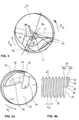
- FIG 1 12 shows a preferred embodiment of an integrally formed installation mandrel 1.
- Such installation mandrels 1 are used in an installation tool W, with which a wire-threaded insert D is installed in a threaded bore of a component.
- a preferred hand held installation tool W is shown figure 11 .
- It comprises a drive unit 3 for rotating the preferred installation spindle 1.
- the drive unit 3 is preferably connected to the drive and holding end 10 of the installation spindle 1 in a rotationally fixed manner. Via an actuating switch 5, according to a preferred Configuration of the installation tool W, the drive unit 3 started or stopped.
- a depth stop 7 preferably determines in a known manner how deep a wire thread insert D with a built-in pin Z that can be bent back can be screwed or dragged into a threaded hole of a component by turning the built-in spindle 1 at most.
- integrally formed installation spindle 1 in an installation machine. This installs a wire thread insert D in a threaded hole in a component using automated work processes.
- the inventively preferred integrally designed installation spindle 1 consists of one piece. This means that there are no moving or immovable parts attached to the installation spindle 1, such as a pivotable or rotatable installation or compression blade.
- the installation spindle 1 is adapted to install a wire thread insert D with an installation pin Z that can be bent back in a threaded bore of a component.
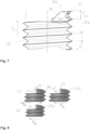
- the wire thread insert D is exemplary in Figure 2b shown. It comprises a cylindrical helix with a plurality of helically wound windings of a wire, in which a first winding has a preferably arcuate driver pin Z without a driver notch, which protrudes over a bending region into the interior of the helix.
- Such wire thread inserts are in EP 2 637 825 B1 1 is explained and illustrated in accordance with various preferred embodiments, which is incorporated herein by reference for a technical understanding of the wire thread insert.
- the installation mandrel 1 has a drive and support end 10 for driving the installation mandrel 1 with a drive module of an installation tool (see Fig 11 ) connect to.
- the drive and holding end 10 is held in the drive module in a detachable manner, preferably via a polygonal end and/or other known coupling structures.
- Such drive and holding ends 10 for holding and transmitting torque to the installation spindle 1 are known in the prior art.
- a functional end 20 of the installation spindle 1 is provided axially opposite the drive and holding end 10 .
- the functional end 20 of the installation spindle 1 preferably has a spindle area 22, ie an external thread 26 rotating to the right or left.
- the spindle area 22 is used to screw on the wire thread insert D in the direction of the drive end 10.
- the wire thread insert D is screwed onto the functional end 20 until the bendable mounting pin Z is held or anchored in a rotationally fixed manner on an axial extension 30 of an axial end face 24 of the mounting spindle 1.
- rotationally fixed means that the installation pin Z and the axial extension 30 form a positive connection, so that the installation spindle 10 rotates the wire thread insert D as well.
- FIG. 1 shows a perspective view of the installation spindle 1
- Figure 2A a lateral sectional view of the installation spindle 1 is reproduced. It can be seen that the axial extension 30 protrudes from the axial end face 24 of the installation spindle 1 in the direction of the longitudinal axis of the installation spindle 1 and thus axially.
- the installation spindle 1 is provided integrally, ie as a whole and firmly connected.
- the installation spindle 1 is made with the axial extension 30 in one piece.
- the axial extension 30 (see below) is subject to wear due to the installation operations of wire thread inserts D, while the rest of the installation mandrel 1 wears less. It is therefore also preferred to manufacture the axial extension 30 separately and then to connect it firmly and integrally to the rest of the installation spindle 1. Cohesive connection methods such as welding and gluing are preferred for this purpose.
- the wire thread insert D would be slipped onto the functional end 20 without a thread in the axial direction until the built-in spigot Z, which can be bent back, has been anchored in a rotationally fixed manner on the axial extension 30 . Thereafter, the wire thread insert D, which is held non-rotatably at the functional end 20, is screwed into the threaded bore of the component, preferably in the same way as is described below.
- the external thread 26 extends on the spindle area 22 of the functional end 20 and on a radial outside 32 of the axial extension 30. Since the axial extension 30 covers only a fraction of the axial end face 24 of the installation spindle, preferably a proportion of less than 50% of the axial end face 24, the external thread 26 continues as at least one length-reduced thread 34 on the radial outside of the axial extension 30--that is, in the circumferential extension of the installation spindle.
- the axial extension 30 has a height relative to the axial end face 24 of the installation spindle 1, so that two or more length-reduced thread turns 34 are arranged on the radial outside 32 of the axial extension 30 and running in the circumferential direction of the installation spindle 1.
- a geometric design of the preferably at least two length-reduced thread turns 34 is discussed in more detail below.
- FIGS 3, 4a and 5 show views of preferred embodiments of the axial face 24 of the installation spindle 1.
- the axial extension 30 is preferably eccentric with respect the end face 24 arranged and protrudes from this.
- only one axial extension 30 is preferably provided on the axial end face 24 in order to screw the wire thread insert D into the threaded bore and to bend the mounting pin back into the internal thread.
- the preferred axial extension 30 occupies an area of less than 50%, preferably in the range of 30 to 40%, of the axial end face 24 .
- the axial extension 30 preferably consists at least of the radial outer side 32 in the form of a wall viewed in the circumferential direction of the functional end 20 with a course and an extent in the form of a circular arc.
- the course of a circular arc an approximation by a curvilinear course is used.
- the axial extension 30 has a preferred radial width B of 0.1 R ⁇ B ⁇ 0.8 R, which is variable in the circumferential direction, with R describing the radius of the functional end 20 .
- B is not necessarily constant along the radial outside 32, so that the axial extension 30 can have an irregular shape with an arcuate radial side in an axial plan view.
- the axial extension 30 has a ramp 36 on a side facing away from the drive and holding end 10 .
- the ramp 36 preferably rises continuously in an angular range of 5° ⁇ ⁇ ⁇ 40° up to the axially highest point or axially furthest point from the holding end 10 of the axial extension 30.
- the bevel 36 consists of a strip surface which runs onto the axial extension 30 in an inclined axial direction. It is also preferred to provide the ramp 36 as a web or bead-like thickening that runs onto the axial extension 30 .
- the different preferred configurations of the ramp 36 allow the radially inwardly bent mounting pin Z of the wire thread insert D to run onto the axial extension 30 while the wire thread insert D is being screwed onto the functional end 20.
- the wire thread insert D is preferably held on a driver shoulder 38 and rotated with the installation spindle 1 .
- the driver shoulder 38 consists of an approximately axially extending web or stop. This is arranged between the axial end face 24 and a starting point of the ramp 36 viewed in the circumferential direction of the installation spindle 1, as in FIGS figures 4b and 5 can be seen. Since the functional end 20 of the installation spindle 1 is already sufficiently screwed into the wire thread insert D, the installation spigot Z hits the driver shoulder 38 during the further rotation of the installation spindle 1 in the screwing-in direction RE The installation pin Z snaps over the axial extension 30.
- At least one thread turn 34 of reduced length is preferably provided on the radial outside 32 of the axial extension 30 as a continuation of the external thread 26 on the functional end 20 . Since the axial extension 30 only extends along part of the circumference of the functional end 20, the length of the at least one thread 34 is reduced.
- the at least one length-reduced thread 34 preferably extends in exactly the same way as the axial extension 30 over an angle of rotation ⁇ in the range of 30° ⁇ 180°.
- the axial extension 30 preferably extends over the angle of rotation ⁇ 90°.
- the angle of rotation ⁇ between the driver shoulder 38 at the front end of the axial extension 30 in the screwing-in direction RE and an axial reverse bending surface 40 at the rear end of the axial extension 30 in the screwing-in direction R E is determined.
- the axial extension 30 protrudes approximately a height H beyond the axial end face 24 .
- the axial height H (see Figure 2a ) is in a range of 0.5 ⁇ P ⁇ H ⁇ 2.5 P, in particular 0.7 P ⁇ H ⁇ 1.5 P, where P describes a pitch of the thread 26 at the functional end 20 of the installation spindle 1 .
- the axial extension 30 preferably has at least one reduced-length thread 34 on its radial, arcuate outer side 32.
- two reduced-length threads 34a, 34b are preferably provided, arranged next to one another in the axial direction. These are in the figures 4b , 6 and 7 to recognize.
- the threads 34a and 34b are preferably formed geometrically in the same way as the external thread 26 on the functional end 20.
- only the thread 34a, which faces the holding end 10, is designed geometrically in the same way as the external thread 26.
- the axially outer length-reduced thread 34b preferably has a larger core diameter than the external thread 26. Due to this preferred increase in the core diameter and thus also the core radius in the thread 34b, when the installation spindle 1 is preferably rotated back, the installation pin Z is more firmly inserted into the internal thread of the threaded bore of the component pressed than with the external thread 26.
- the thread 34b therefore preferably interacts with the axial reverse bending surface 40 explained in more detail below and ensures that the installation pin Z is permanently bent back into the internal thread of the threaded bore of the component.
- the core diameter of the thread 34b is preferably 3% to 20%, preferably 5-17% larger than the core diameter of the external thread 26.
- the axially outermost thread flank 35 in the screwing-in direction RE is shortened in the radial direction compared to the adjacent thread flank of the thread 34a.
- a radius of the axially outermost thread flank 35 is preferably 2 to 15% smaller than the radius of the immediately adjacent, non-shortened thread flank.
- the axial reverse bending surface 40 is arranged at the end of the axial extension 30 in relation to the screwing direction R E of a wire thread insert D into a threaded bore.
- the installation pin Z is supported on the axial reverse bending surface 40 while the functional end 20 is being unscrewed from the wire thread insert D and is bent radially outwards by the functional end 20 into the internal thread of the threaded bore during the unscrewing.
- the axial bending back surface 40 and a bending shoulder 42 preferably act on the mounting pin Z alternately, individually or in combination.
- the bending shoulder 42 (see Figures 3, 4a , 5 , 7 ) is preferably formed by the transition surface or the transition edge between the reverse bending surface 40 and the axially outer reduced-length thread 34b or the at least two axially outer reduced-length threads 34a, 34b.
- the installation pin Z is initially supported on the reverse bending surface 40 and its free end is pressed in the direction of the reduced-length thread 34b.
- This process is supported by the radially similar arrangement of the reverse bending surface 40 .
- radially similar means that the reverse bending surface 40 runs essentially in the radial direction on the end face of the installation spindle. Since the reverse bending surface 40 does not necessarily begin at the center of the end face, but can also start off-center, it is aligned similarly to the radius of the installation spindle.
- the reverse bending surface 40 preferably bends the installation pin Z into the internal thread of the threaded bore.
- the free end of the mounting pin Z preferably does not yet run into the reduced-length thread 34b.
- This process is based on a torque measurement on a preferred embodiment of the invention figure 9 shown in points 0 to 2.
- the torque ⁇ applied by the installation spindle 1 is plotted on the y-axis. It assumes negative values because installation spindle 1 is rotated backwards.
- the time is plotted on the x-axis.
- the installation spigot Z is pushed or bent radially outwards and the free end of the installation spigot Z is aligned with the bending shoulder 42 at the transition to the reduced-length thread 34b so that the bent-back installation spigot Z can run into the thread 34b.
- the entry of the installation pin Z into the thread 34b can be seen preferably between points 3 and 4. Due to the already achieved curvature of the mounting pin Z during bending back, the mounting pin Z preferably runs into the thread 34b under the effect of a reduced or decreasing torque compared to the previous steps.
- the torque is preferably increased again during the further reverse rotation of the installation spindle 1 between points 4 and 5 .
- the larger core radius of the thread 34b acts preferably in comparison to the other threads of the external thread 26, in that it forces or bends the installation pin Z further radially outwards into the internal thread of the threaded bore.
- the mounting spindle 1 is unscrewed from the wire thread insert D with reduced torque.
- the bending-back surface 40 is arranged at a preferred angle ⁇ to the axial end face 24 (see FIG figure 6 ).
- the angle ⁇ is preferably in the range of 65° ⁇ 90°, in particular 70° ⁇ 85°.
- the axial face 24 is a flat surface.
- the above angle ⁇ is enclosed by the end face 24 and the reverse bending surface 40 .
- At least the axial extension 30 of the installation spindle 1 with its preferred geometric features is manufactured by a machining process, such as milling.
- a machining process such as milling.
- a depression 44 is formed in the axial direction in the end face 24 .
- the indentation 44 preferably borders on the reverse bending surface 40 .
- it preferably has an elongate shape running along the front edge of the reverse bending surface 40 .
- the indentation 44 at the end foot of the bending back surface 40 has proven to be advantageous when bending back an installation spigot Z of the wire thread insert D into an internal thread of the threaded bore of a component. This is because the indentation 44 preferably supports catching and holding of the installation spigot Z on the reverse bending surface 40 in order to ensure transmission of the reverse bending forces from the reverse bending surface 40 to the installation spigot Z.
- the recess 44 also causes the angle ⁇ adjacent to the front edge of the reverse bending surface 40 to be enlarged by an angular range of 0.5 to 5°. This preferably leads to an increased overhang of the reverse bending surface 40 over an installation pin Z caught at the angle ⁇ and to be bent back.
- the thread 34b is cut through the reverse bending surface 40 .
- the thread flank 35 protrudes beyond the bending shoulder 42 in the direction of reverse rotation R R .
- the bending-up shoulder 42 which is set back counter to the direction of reverse rotation R R , is preferably concave (see Figure 8a, b ) or rectilinear (see Figure 8c ) shaped.
- the concavely shaped reverse bending shoulder 42 preferably supports the hold of the installation pin Z on the bending shoulder 42 as the curvature increases.
- step S1 the wire thread insert D is screwed or slipped onto the installation spindle 1 according to one of the configurations described above. This step is completed when the wire thread insert D is held in a form-fitting manner on the functional end 20 of the installation spindle 1 .
- the driver pin Z is preferably coupled to the axial extension 30 of the installation spindle 1 in a form-fitting manner.
- step S2 the wire thread insert D is screwed into the internal thread or receiving thread of the threaded hole of the component using the installation spindle 1 .
- the direction of rotation of the installation spindle 1 is reversed.
- the installation spindle 1 is now turned in the opposite direction to the screwing-in direction.
- the driving pin Z is bent back into the receiving thread of the threaded bore of the component, as described in detail above.
- the axial extension 30 engages the driving pin Z via the bending-back surface 40 and the bending-open shoulder 42 and bends it into the receiving thread of the threaded bore.
- the bending back is supplemented or assisted by the action of the enlarged core diameter threaded portion 34b, since this also urges or bends the tang Z radially outward.
- the installation spindle 1 is completely spindled out or removed from the wire thread insert D (step S5).
Abstract
Die vorliegende Erfindung offenbart eine integral ausgebildete Einbauspindel angepasst an einen Drahtgewindeeinsatz, der eine zylindrische Wendel mit einer Mehrzahl von schraubenförmig gewickelten Windungen eines Drahts aufweist, in der eine erste Windung einen über einen Biegebereich in ein Inneres der Wendel ragenden vorzugsweise bogenförmigen Mitnehmerzapfen ohne Mitnehmerkerbe umfasst, mit der der Drahtgewindeeinsatz in einer Eindrehrichtung in eine Gewindebohrung eines Bauteils eindrehbar ist, wobei die Einbauspindel die folgenden Merkmale aufweist: ein Antriebs- und Halteende zum Drehen und Halten der Einbauspindel in einem Einbauwerkzeug und ein Funktionsende zum Installieren des Drahtgewindeeinsatzes in einer Gewindebohrung eines Bauteils; von einer axialen Stirnseite der Einbauspindel an dem Funktionsende steht ein axialer Fortsatz in Richtung einer Längsachse der Einbauspindel vor, der entlang einer Umfangserstreckung der Einbauspindel durch eine bogenförmige radiale Außenseite in einem Drehwinkel α aus einem Bereich von 30° ≤ α ≤ 180° begrenzt ist; bezogen auf die Eindrehrichtung weist der axiale Fortsatz beginnend an einem vorderen Ende der bogenförmigen radialen Außenseite eine Auflaufschräge auf, die sich in axialer Richtung der Einbauspindel ansteigend als eine Streifenfläche auf dem axialen Fortsatz erstreckt; und bezogen auf die Eindrehrichtung fällt der axiale Fortsatz an einem hinteren Ende der bogenförmigen radialen Außenseite in einer axialen Rückbiegefläche axial ab, die radialähnlich angeordnet ist.The present invention discloses an integrally formed installation spindle adapted to a wire thread insert, which has a cylindrical helix with a plurality of helically wound windings of a wire, in which a first winding comprises a preferably arcuate driving pin without a driving notch projecting over a bending region into an interior of the helix, with which the wire thread insert can be screwed into a threaded hole of a component in a screwing-in direction, the installation spindle having the following features: a drive and holding end for rotating and holding the installation spindle in an installation tool and a functional end for installing the wire thread insert in a threaded hole of a component; from an axial end face of the installation spindle at the functional end, an axial extension protrudes in the direction of a longitudinal axis of the installation spindle, which is delimited along a circumferential extent of the installation spindle by an arcuate radial outer side at an angle of rotation α from a range of 30° ≤ α ≤ 180°; in relation to the screwing-in direction, the axial extension has, starting at a front end of the arcuate radial outer side, a run-on slope which extends in the axial direction of the installation spindle, increasing as a strip surface on the axial extension; and with respect to the screwing-in direction, the axial extension at a rear end of the arcuate radial outside axially falls in an axial reverse bending surface which is radially similarly arranged.
Description
Die vorliegende Erfindung betrifft eine integral ausgebildete Einbauspindel angepasst an einen Drahtgewindeeinsatz, einen Nachrüstsatz für ein Installationswerkzeug mit einer Mehrzahl von derartigen Einbauspindeln, ein Installationswerkzeug bestehend aus einem Antriebsmodul und einer integral ausgebildeten Einbauspindel sowie ein Installationsverfahren eines Drahtgewindeeinsatzes mit zurückbiegbarem, nicht entfernbarem Mitnehmerzapfen mithilfe des oben genannten Installationswerkzeugs.The present invention relates to an integrally formed installation mandrel adapted to a wire thread insert, a retrofit kit for an installation tool with a plurality of such installation mandrels, an installation tool consisting of a drive module and an integrally formed installation mandrel and an installation method of a wire thread insert with a bendable, non-removable driving pin using the above mentioned installation tool.
Im Stand der Technik sind verschiedene technische Lösungen zum Einbau eines Drahtgewindeeinsatzes in einer Gewindebohrung bekannt. Die zur Installation des Drahtgewindeeinsatzes in der Gewindebohrung verwendete Einbauspindel richtet sich nach der konstruktiven Ausgestaltung des zu installierenden Drahtgewindeeinsatzes. Denn die verschiedenen Konstruktionen von Drahtgewindeeinsätzen weisen beispielsweise einen radial einwärts ragenden gerade ausgebildeten Einbauzapfen auf, der nach der Installation aus der Konstruktion des Drahtgewindeeinsatzes ausgebrochen wird. Eine weitere Konstruktion sieht vor, den Drahtgewindeeinsatz mit einer radial einwärts angeordneten Kerbe bereitzustellen. In diese Kerbe greift ein entsprechender Mitnehmer ein, um den Drahtgewindeeinsatz in das Innengewinde einzuschrauben. Diese Konstruktion erfordert nicht, dass nach der Installation des Drahtgewindeeinsatzes ein Einbauzapfen entfernt werden muss. Eine weitere konstruktive Alternative eines Drahtgewindeeinsatzes weist einen radial einwärts gebogenen Einbauzapfen mit oder ohne Kerbe auf. Dieser Einbauzapfen wird nach abgeschlossener Installation radial auswärts in das Innengewinde der Gewindebohrung zurückgebogen.Various technical solutions for installing a wire thread insert in a threaded hole are known in the prior art. The installation mandrel used to install the wire thread insert in the threaded hole depends on the design of the wire thread insert to be installed. This is because the various constructions of wire thread inserts have, for example, a radially inwardly projecting, straight installation spigot which is broken out of the construction of the wire thread insert after installation. Another design is to provide the wire thread insert with a notch located radially inward. A corresponding driver engages in this notch in order to screw the wire thread insert into the internal thread. This design does not require the removal of a mounting stud after the wire thread insert is installed. A further constructive alternative of a wire thread insert has a radially inwardly bent installation spigot with or without a notch. After installation is complete, this mounting pin is bent back radially outwards into the internal thread of the threaded hole.
Aufgrund der verschiedenen technischen Lösungen von Drahtgewindeeinsätzen variiert auch die Zahl der im Stand Technik bekannten Konstruktionen von Einbauspindeln zur Installation des jeweiligen Drahtgewindeeinsatzes in der Gewindebohrung eines Bauteils.Due to the different technical solutions for wire thread inserts, the number of constructions of installation spindles known in the prior art for installing the respective wire thread insert in the threaded hole of a component also varies.
Gemäß
Die oben beschriebenen technischen Lösungen zum Einbau eines Drahtgewindeeinsatzes mit einem lösbaren Einbauzapfen haben den Nachteil, dass der gelöste Einbauzapfen entweder nach erfolgter Installation und Lösung eingesammelt werden muss oder im Bauteil verbleibt. Das Verbleiben des gelösten Einbauzapfens im Bauteil kann zu Störungen, Geräuschen oder Blockaden bei der weiteren Montage des Bauteils führen.The technical solutions described above for installing a wire thread insert with a detachable installation spigot have the disadvantage that the detached installation spigot either has to be collected after installation and detachment has taken place or it remains in the component. If the loosened mounting pin remains in the component, this can lead to disruptions, noise or blockages during further assembly of the component.
Das
Die konstruktiv komplexe Installationsspindel zum Einbau des Drahtgewindeeinsatzes mit zurückbiegbarem Einbauzapfen muss geeignet angesteuert werden, um alle konstruktiven Merkmale während des Einbaus des Drahtgewindeeinsatzes anwenden zu können.The constructively complex installation spindle for installing the wire thread insert with bendable installation spigot must be controlled in a suitable manner in order to be able to use all the constructive features during the installation of the wire thread insert.
Im Hinblick auf die bekannte Konstruktion einer Einbauspindel für einen Drahtgewindeeinsatz mit zurückbiegbarem Einbauzapfen gemäß
Die obige Aufgabe wird gelöst durch eine integral ausgebildete Einbauspindel gemäß dem unabhängigen Patentanspruch 1, einen Nachrüstsatz für ein Installationswerkzeug mit Antriebsmodul und lösbarer Einbauspindel mit mindestens zwei integral ausgebildeten Einbauspindeln gemäß dem unabhängigen Patentanspruch 9, ein Installationswerkzeug mit der integral ausgebildeten Einbauspindel gemäß dem unabhängigen Patentanspruch 10 sowie durch ein Installationsverfahren eines Drahtgewindeeinsatzes mit Hilfe des erfindungsgemäßen Installationswerkzeugs gemäß dem unabhängigen Patentanspruch 11. Vorteilhafte Ausgestaltungen und Weiterentwicklungen vorliegender Erfindung ergeben sich aus der folgenden Beschreibung, den begleitenden Zeichnungen und den anhängenden Patentansprüchen.The above object is achieved by an integrally formed installation spindle according to
Vorliegende Erfindung offenbart eine integral ausgebildete Einbauspindel angepasst an einen Drahtgewindeeinsatz, der eine zylindrische Wendel mit einer Mehrzahl von schraubenförmig gewickelten Windungen eines Drahts aufweist, in der eine erste Windung einen über einen Biegebereich in ein Inneres der Wendel ragenden vorzugsweise bogenförmigen Mitnehmerzapfen ohne Mitnehmerkerbe umfasst, mit der der Drahtgewindeeinsatz in einer Eindrehrichtung in eine Gewindebohrung eines Bauteils eindrehbar ist. Die erfindungsgemäße Einbauspindel weist die folgenden Merkmale auf: ein Antriebs- und Halteende zum Drehen und Halten der Einbauspindel in einem Einbauwerkzeug und ein Funktionsende zum Installieren des Drahtgewindeeinsatzes in einer Gewindebohrung eines Bauteils, von einer axialen Stirnseite der Einbauspindel an dem Funktionsende steht ein axialer Fortsatz in Richtung einer Längsachse der Einbauspindel vor, der entlang einer Umfangserstreckung der Einbauspindel durch eine bogenförmige radiale Außenseite in einem Drehwinkel α aus einem Bereich von 30 °≤ α ≤ 180 ° begrenzt ist, bezogen auf die Eindrehrichtung weist der axiale Fortsatz beginnend an einem vorderen Ende der bogenförmigen radialen Außenseite eine Auflaufschräge auf, die sich in axialer Richtung der Einbauspindel ansteigend auf dem axialen Fortsatz erstreckt, und bezogen auf die Eindrehrichtung fällt der axiale Fortsatz an einem hinteren Ende der bogenförmigen radialen Außenseite in einer axialen Rückbiegefläche axial ab, die radialähnlich angeordnet ist.The present invention discloses an integrally formed installation spindle adapted to a wire thread insert, which has a cylindrical helix with a plurality of helically wound windings of a wire, in which a first winding comprises a preferably arcuate driving pin without a driving notch, which protrudes over a bending region into an interior of the helix which the wire thread insert can be screwed into a threaded hole of a component in a screwing-in direction. The installation mandrel of the present invention has the following features: a drive and holding end for rotating and holding the installation mandrel in an installation tool, and an operational end for installing the wire thread insert into a threaded bore of a component from an axial face of the installation spindle at the functional end, an axial extension protrudes in the direction of a longitudinal axis of the installation spindle, which is delimited along a circumferential extension of the installation spindle by an arcuate radial outside at an angle of rotation α from a range of 30 ° ≤ α ≤ 180 °, based on the screwing-in direction the axial extension, starting at a front end of the arcuate radial outside, has a run-on slope that extends in the axial direction of the installation spindle and increases on the axial extension, and in relation to the screwing-in direction, the axial extension falls at a rear end of the arcuate radial outside in a axial reverse bending surface axially, which is arranged radially similar.
Die erfindungsgemäße integral ausgebildete Einbauspindel ist als robuste einteilig ausgebildete Einbauspindel konstruiert, die in einem Einbauwerkzeug für Drahtgewindeeinsätze austauschbar einsetzbar ist. Im Vergleich zu bekannten Einbauspindeln für Drahtgewindeeinsätze mit zurückbiegbarem Einbauzapfen ist die vorliegende Einbauspindel aufgrund der Einteiligkeit robuster im Einsatz und zeichnet sich somit durch eine höhere Standfestigkeit bzw. Lebensdauer im Vergleich zu mehrteiligen Einbauspindeln aus.The integral installation mandrel according to the invention is constructed as a robust one-piece installation mandrel which can be used interchangeably in an installation tool for wire thread inserts. Compared to known installation mandrels for wire thread inserts with bendable installation spigot, the present installation mandrel is more robust in use due to the one-piece design and is therefore characterized by a higher stability and service life compared to multi-part installation mandrels.
Zentrales Element der Einbauspindel ist an einem Funktionsende der Einbauspindel, also dem Ende, auf welches der einzubauende Drahtgewindeeinsatz mit zurückbiegbarem Einbauzapfen aufgespindelt oder aufgesteckt wird, ein axialer Fortsatz, der an der axialen Stirnseite der Einbauspindel an deren Funktionsende angeordnet ist. Dieser vorzugsweise nur eine axiale Fortsatz ist in seiner Form derart ausgebildet, dass er nach dem Aufspindeln des Drahtgewindeeinsatzes mit zurückbiegbarem Einbauzapfen mit diesem eine drehfeste Verbindung bildet. Zu diesem Zweck schnappt beim Aufspindeln des Drahtgewindeeinsatzes der zurückbiegbare Einbauzapfen über den axialen Fortsatz, bis er sich an diesem nach weiterer Umdrehung der Einbauspindel drehfest verhakt. Diese drehfeste, formschlüssige Verbindung sorgt für ein problemloses ein Drehen bzw. Einschrauben des Drahtgewindeeinsatzes in das Innengewinde der Gewindebohrung eines Bauteils.The central element of the installation spindle is an axial extension at a functional end of the installation spindle, i.e. the end onto which the wire thread insert to be installed with a bendable installation pin is screwed or plugged, which is arranged on the axial end face of the installation spindle at its functional end. This preferably only one axial extension is designed in its shape in such a way that it forms a non-rotatable connection with the wire thread insert with the built-in pin that can be bent back after it has been screwed on. For this purpose, when the wire thread insert is screwed on, the bendable built-in spigot snaps over the axial extension until, after further rotation of the built-in spindle, it snaps onto it in a rotationally fixed manner. This non-rotatable, positive connection ensures that the wire thread insert can be rotated or screwed into the internal thread of the threaded hole in a component without any problems.
Um den radial einwärts gebogenen Einbauzapfen problemlos an dem axialen Fortsatz verhaken oder verankern zu können, gleitet dieser die Auflaufschräge in axialer Richtung der Einbauspindel hinauf, bis er am Ende der Auflaufschräge von dem axialen Fortsatz wieder abrutscht. Auf diese Weise bildet die streifenförmig ausgebildete Auflaufschräge die Vorbereitung für eine federnde Schnappverbindung zwischen dem radial einwärts gebogenen, zurückbiegbaren Einbauzapfen und dem axialen Fortsatz an der axialen Standfläche der Einbauspindel.In order to be able to hook or anchor the radially inwardly bent installation pin to the axial extension without any problems, it slides up the ramp in the axial direction of the installation spindle until it slips off the axial extension again at the end of the ramp. In this way, the strip-shaped ramp forms the preparation for a resilient snap connection between the radially inwardly bent, bendable mounting pin and the axial extension on the axial base of the mounting spindle.
Nach erfolgtem Einbau des Drahtgewindeeinsatzes ist die Einbauspindel durch Drehen entgegen der Einbaudrehrichtung aus dem Drahtgewindeeinsatz entfernbar. Neben dem Entfernen der Einbauspindel aus dem Drahtgewindeeinsatz sorgt diese Rückwärtsdrehung der Einbauspindel gleichzeitig für ein Zurückbiegen des zurückbiegbaren Einbauzapfens in das Innengewinde der Gewindebohrung. Da bevorzugt der axiale Fortsatz am der Auflaufschräge gegenüberliegenden Ende in einer Rückbiegefläche ausläuft, drückt diese Rückbiegefläche den Einbauzapfen bei einer Rückdrehung der Einbauspindel radial nach außen in Richtung Innengewinde der Gewindebohrung. Somit stellt der vorzugsweise nur eine axiale Fortsatz an der axialen Stirnseite der Einbauspindel einen multifunktionalen, axialen Fortsatz dar. Dieser multifunktionale Fortsatz unterstützt den Einbauvorgang des Drahtgewindeeinsatzes in die Gewindebohrung durch seine streifenflächenähnliche Auflaufschräge und beendet zudem den Einbauvorgang durch ein Zurückbiegen des Einbauzapfens in das Innengewinde der Gewindebohrung mithilfe der Rückbiegefläche.After the wire thread insert has been installed, the installation spindle can be removed from the wire thread insert by turning it in the opposite direction to the installation direction of rotation. In addition to removing the installation mandrel from the wire thread insert, this reverse rotation of the installation mandrel simultaneously deflects the reversible installation post back into the internal threads of the threaded bore. Since he prefers If the axial extension ends in a reverse bending surface at the end opposite the ramp, this reverse bending surface presses the mounting pin when the mounting spindle is turned back radially outwards in the direction of the internal thread of the threaded bore. Thus, the preferably only one axial extension on the axial end face of the installation spindle represents a multifunctional, axial extension. This multifunctional extension supports the installation process of the wire thread insert in the threaded hole through its strip surface-like ramp and also ends the installation process by bending the installation pin back into the internal thread of the Threaded hole using the reverse bending surface.
Gemäß einer bevorzugten Ausführungsform vorliegender Erfindung weist der axiale Fortsatz mindestens einen in Umfangsrichtung längenreduzierten Gewindegang auf.According to a preferred embodiment of the present invention, the axial extension has at least one thread that is reduced in length in the circumferential direction.
Wie bereits oben erwähnt worden ist, steht der axiale Fortsatz von der axialen Stirnseite am Funktionsende der Einbauspindel vor. Die radiale Außenseite des axialen Fortsatzes erstreckt sich in Umfangsrichtung der Einbauspindel. Zudem setzt sich bevorzugt das Gewinde am Funktionsende der Einbauspindel auch an der radialen Außenseite in Form eines bevorzugt längenreduzierten Gewindegangs in Umfangsrichtung des axialen Fortsatzes fort. Vorzugsweise weist der axiale Fortsatz in Abhängigkeit von seiner axialen Höhe, d. h. seinem Überstand über die axiale Stirnseite der Einbauspindel, einen oder zwei Gewindegänge an seiner bogenförmig ausgebildeten radialen Außenseite auf. Es ist ebenfalls bevorzugt, mehr als zwei längenreduzierte Gewindegänge vorzusehen, sollten diese die Installation und/oder das Entfernen der Einbauspindel aus einem installierten Drahtgewindeeinsatz mit zurückbiegbarem Einbauzapfen unterstützen.As has already been mentioned above, the axial extension protrudes from the axial end face at the functional end of the installation spindle. The radial outside of the axial extension extends in the circumferential direction of the installation spindle. In addition, the thread on the functional end of the installation spindle preferably also continues on the radial outside in the form of a preferably reduced-length thread in the circumferential direction of the axial extension. Preferably, depending on its axial height, i. H. its overhang on the axial end face of the installation spindle, one or two threads on its arcuate radial outside. It is also preferred to provide more than two reduced length threads should they aid in the installation and/or removal of the installation mandrel from an installed retractable installation stem wire threaded insert.
Weiter bevorzugt steht der axiale Fortsatz am Funktionsende der Einbauspindel einzeln an der axialen Stirnseite axial vor.More preferably, the axial extension at the functional end of the installation spindle individually protrudes axially on the axial end face.
Zudem ist es erfindungsgemäß bevorzugt, dass der axiale Fortsatz weniger als 40 % der axialen Stirnseite am Funktionsende einnimmt.In addition, it is preferred according to the invention that the axial extension occupies less than 40% of the axial end face at the functional end.
Um die multifunktionale Wirkung des axialen Fortsatzes sicherzustellen, nimmt dieser vorzugsweise eine Fläche von weniger als 50 % der axialen Stirnseite am Funktionsende der Einbauspindel ein. Dieser Flächenanteil, der auch auf 25-35 % reduziert werden kann, ist ausreichend, um die drehfeste Einbauhalterung des Drahtgewindeeinsatzes am axialen Fortsatz zu realisieren sowie um den zurückbiegbaren Einbauzapfen bei der Deinstallation der Einbauspindel wirkungsvoll und ausreichend in das Innengewinde der Gewindebohrung zurückzubiegen.In order to ensure the multifunctional effect of the axial extension, this preferably occupies an area of less than 50% of the axial end face at the functional end of the built-in spindle. This surface area, which can also be reduced to 25-35%, is sufficient to realize the non-rotatable mounting bracket for the wire thread insert on the axial extension and to effectively and sufficiently bend back the bendable mounting pin into the internal thread of the threaded hole when the mounting spindle is uninstalled.
Gemäß einer bevorzugten Ausgestaltung vorliegender Erfindung weist der axiale Fortsatz an der radialen Außenseite zwei längenreduzierte Gewindegänge auf, die in mindestens einer der folgenden Größen unterschiedlich ausgebildet sind: umfängliche Länge, Kerndurchmesser und Steigung.According to a preferred embodiment of the present invention, the axial extension has two length-reduced thread turns on the radial outside, which are designed differently in at least one of the following sizes: circumferential length, core diameter and pitch.
Um ein effektives Aufspindeln des Drahtgewindeeinsatzes mit zurückbiegbarem Einbauzapfen und damit ein wirkungsvolles Verankern des Einbauzapfens zum Eindringen des Drahtgewindeeinsatzes in die Gewindebohrung zu gewährleisten, sind vorzugsweise an der in Umfangsrichtung verlaufenden radialen Außenseite zwei längenreduzierte Gewindegänge vorgesehen. Während des Aufspindelns des Drahtgewindeeinsatzes auf das Funktionsende der Einbauspindel dienen die längenreduzierten Gewindegänge der Führung der Drahtwendel des Drahtgewindeeinsatzes. Sobald sich der zurückbiegbare Einbauzapfen am axialen Fortsatz drehfest hält, wird dieser Halt ebenfalls durch den Verlauf der Drahtwendel des Drahtgewindeeinsatzes in zumindest einem der längenreduzierten Gewindegänge unterstützt.In order to ensure effective screwing on of the wire thread insert with bendable mounting pin and thus effective anchoring of the mounting pin for penetrating the wire thread insert into the threaded bore, two reduced-length threads are preferably provided on the radial outside running in the circumferential direction. While the wire thread insert is being screwed onto the functional end of the installation spindle, the reduced-length threads serve to guide the wire helix of the wire thread insert. As soon as the bendable built-in pin is held in a rotationally fixed manner on the axial extension, this hold is also supported by the course of the wire helix of the wire thread insert in at least one of the length-reduced thread turns.
Während diese Unterstützung den Einlaufvorgang stabilisiert, sorgt eine bestimmte Formgebung der längenreduzierten Gewindegänge für ein effektives Zurückbiegen des zurückbiegbaren Einbauzapfens in das Innengewinde der Gewindebohrung. Zu diesem Zweck werden beispielsweise der Kerndurchmesser und/oder die Steigung der beiden längenreduzierten Gewindegänge im Vergleich zu dem übrigen Gewinde der Einbauspindel anders ausgestaltet. Alternativ dazu werden der Kerndurchmesser und/oder die Steigung nur eines längenreduzierten Gewindegangs im Vergleich zu dem übrigen Gewinde der Einbauspindel anders ausgestaltet. So unterstützt vorzugsweise ein größerer Kerndurchmesser nur des axial äußeren längenreduzierten Gewindegangs oder beider längenreduzierter Gewindegänge ein Zurückbiegen des zurückbiegbaren Einbauzapfens in das Innengewinde der Gewindebohrung.While this support stabilizes the running-in process, a specific shape of the length-reduced threads ensures that the bendable mounting pin is effectively bent back into the internal thread of the threaded hole. For this purpose, for example, the core diameter and/or the pitch of the two length-reduced thread turns are designed differently compared to the remaining thread of the installation spindle. As an alternative to this, the core diameter and/or the pitch of only one length-reduced thread turn are designed differently in comparison to the remaining thread of the installation spindle. Thus, preferably, a larger core diameter of only the axially outer reduced-length thread or both reduced-length threads supports a bending back of the built-in pin that can be bent back into the internal thread of the threaded bore.
Zudem ist es bevorzugt, eine im Vergleich zu dem übrigen Gewinde der Einbauspindel größere Steigung eines oder beider längenreduzierter Gewindegänge zu nutzen, um ein Zurückbiegen des zurückbiegbaren Einbauzapfens in das Innengewinde der Gewindebohrung zu unterstützen.In addition, it is preferred to use a pitch of one or both reduced-length threads that is greater than the rest of the thread of the installation spindle in order to support bending back of the installation pin that can be bent back into the internal thread of the threaded bore.
Mithilfe der Variation der umfänglichen Länge, vorzugsweise einer Vergrößerung der umfänglichen Länge, mindestens eines längenreduzierten Gewindegangs wird ebenfalls bevorzugt eine zusätzliche Führung der Wendel des Drahtgewindeeinsatzes durch den axialen Fortsatz sichergestellt.With the help of the variation of the circumferential length, preferably an increase in the circumferential length, of at least one length-reduced thread turn, an additional guidance of the helix of the wire thread insert through the axial extension is also preferably ensured.
Vorzugsweise hat der axial äußere längenreduzierte Gewindegang im Vergleich zu dem benachbarten längenreduzierten Gewindegang einen größeren Kerndurchmesser und/oder eine größere Steigung.The axially outer reduced-length thread preferably has a larger core diameter and/or a greater pitch in comparison to the adjacent reduced-length thread.
Gemäß einer weiteren bevorzugten Ausführungsform vorliegender Erfindung weist der axiale Fortsatz in axialer Richtung zwischen der axialen Stirnseite des Funktionsendes und dem vorderen Ende der Auflaufschräge einen Axialsteg als eine Mitnahmeschulter auf, die angepasst ist, um einen Drahtgewindeeinsatz beim Eindrehen in eine Gewindebohrung drehfest zu halten.According to a further preferred embodiment of the present invention, the axial extension has an axial web in the axial direction between the axial end face of the functional end and the front end of the ramp as a driving shoulder, which is adapted to hold a wire thread insert in a rotationally fixed manner when it is screwed into a threaded bore.
Während des Aufspindelns des Drahtgewindeeinsatzes auf das Funktionsende der Einbauspindel wird bevorzugt der axiale Fortsatz aus einem Inneren des Drahtgewindeeinsatzes in axialer Richtung herausgeschraubt. Sofern der axiale Fortsatz nur geringfügig über das Innere des Drahtgewindeeinsatzes hinausragen sollte, gleitet der zurückbiegbare Einbauzapfen entlang der Auflaufschräge auf dem axialen Fortsatz ab und das Einschrauben der Einbauspindel in den Drahtgewindeeinsatz bzw. das Aufspindeln des Drahtgewindeeinsatzes auf das Funktionsende der Einbauspindel wird fortgesetzt. Sobald der axiale Fortsatz bevorzugt ausreichend weit aus dem Inneren des Drahtgewindeeinsatzes hervorragt, kann der Einbauzapfen nicht mehr auf die Auflaufschräge auflaufen und dort über den axialen Fortsatz gleiten. Stattdessen bleibt der zurückbiegbare Einbauzapfen an der bevorzugten Mitnahmeschulter bzw. dem dafür vorgesehenen Axialsteg hängen und bildet auf diese Weise eine drehfeste Verbindung zwischen dem Funktionsende der Einbauspindel und dem aufgespindelten Drahtgewindeeinsatz. Somit bilden die Mitnehmerschulter bzw. der Axialsteg, welcher zwischen dem Beginn der Auflaufschräge und der angrenzenden axialen Stirnseite der Einbauspindel angeordnet ist, eine formschlüssige Verbindung mit dem Einbauzapfen, der ein weiteres Aufspindeln des Drahtgewindeeinsatzes auf das Funktionsende der Einbauspindel verhindert.While the wire thread insert is being screwed onto the functional end of the installation spindle, the axial extension is preferably unscrewed from an interior of the wire thread insert in the axial direction. If the axial extension protrudes only slightly beyond the inside of the wire thread insert, the bendable mounting pin slides along the ramp on the axial extension and the screwing of the mounting spindle into the wire thread insert or the spinning of the wire thread insert onto the functional end of the mounting spindle continues. As soon as the axial extension preferably protrudes far enough out of the inside of the wire thread insert, the built-in pin can no longer run onto the ramp and slide there over the axial extension. Instead, the built-in pin that can be bent back remains hanging on the preferred driving shoulder or the axial web provided for this purpose and in this way forms a non-rotatable connection between the functional end of the built-in spindle and the screwed-on wire thread insert. Thus, the driver shoulder or the axial web, which is arranged between the beginning of the ramp and the adjacent axial end face of the installation spindle, form a positive connection with the installation pin, which prevents further screwing of the wire thread insert onto the functional end of the installation spindle.
Ebenfalls erfindungsgemäß bevorzugt schließt die axiale Rückbiegefläche mit der angrenzenden axialen Stirnseite des Funktionsendes einen Winkel β im Bereich von 65° ≤ β ≤ 90° ein.Also preferably according to the invention, the axial reverse bending surface encloses an angle β in the range of 65°≦β≦90° with the adjoining axial end face of the functional end.
Am in Umfangsrichtung gegenüberliegenden Ende des axialen Fortsatzes ist die axiale Rückbiegefläche für ein bevorzugtes Zurückbiegen des Einbauzapfens in das Innengewinde der Gewindebohrung vorgesehen. Um den Halt des Einbauzapfens bzw. das Abstützen des Einbauzapfens an der Rückbiegefläche zu unterstützen und ein Überschnappen des zurückbiegbaren Einbauzapfens über die Rückbiegefläche in Richtung Auflaufschräge zu vermeiden, bildet die axiale Rückbiegefläche einen Winkel von kleiner 90° im Vergleich zur axialen Stirnseite der Einbauspindel. Auf diese Weise wird bevorzugt der zurückbiegbare Einbauzapfen in einem spitzen Winkel zwischen Rückbiegefläche und axialer Stirnseite der Einbauspindel gehalten, während er in entgegengesetzter Richtung zum Eindrehen des Drahtgewindeeinsatzes in das Innengewinde der Gewindebohrung gebogen wird.At the opposite end of the axial extension in the circumferential direction, the axial reverse bending surface is provided for a preferred bending back of the mounting pin into the internal thread of the threaded bore. In order to support the installation spigot or the support of the installation spigot on the reverse bending surface and to prevent the bendable installation spigot from snapping over the reverse bending surface in the direction of the ramp, the axial reverse bending surface forms an angle of less than 90° compared to the axial end face of the installation spindle. In this way, the bendable mounting pin is preferably held at an acute angle between the bend-back surface and the axial end face of the mounting spindle, while it is bent in the opposite direction to turning the wire thread insert into the internal thread of the threaded bore.
Vorliegende Erfindung umfasst zudem einen Nachrüstsatz für ein Installationswerkzeug eines Drahtgewindeeinsatzes mit einem miteinander lösbar verbindbaren Antriebsmodul und einer Einbauspindel, der als austauschbare Einbauspindeln mindestens zwei integral ausgebildete Einbauspindeln gemäß einem der oben beschriebenen Ausführungsformen aufweist, die sich in einer Konstruktion und/oder Dimension der Einbauspindel unterscheiden.The present invention also includes a retrofit kit for an installation tool for a wire thread insert with a drive module that can be releasably connected to one another and an installation spindle, which, as exchangeable installation spindles, has at least two integrally designed installation spindles according to one of having the embodiments described above, which differ in a construction and/or dimension of the installation spindle.
Zudem umfasst vorliegende Erfindung ein Installationswerkzeug, insbesondere ein manuelles Installationswerkzeug oder einen Einbauautomat, eines Drahtgewindeeinsatzes mit einem miteinander lösbar verbindbaren Antriebsmodul und einer integral ausgebildeten Einbauspindel gemäß einer der oben beschriebenen Ausführungsformen.In addition, the present invention includes an installation tool, in particular a manual installation tool or an installation machine, a wire thread insert with a drive module that can be releasably connected to one another and an integrally formed installation spindle according to one of the embodiments described above.
Die oben beschriebene integral ausgebildete Einbauspindel mit ihren unterschiedlichen konstruktiven Ausgestaltungen wird innerhalb eines Installationswerkzeugs zum Installieren von Drahtgewindeeinsätzen verwendet. Zu derartigen Installationswerkzeugen zählen einerseits manuell genutzte Installationswerkzeuge. Derartige Installationswerkzeuge werden von einem Werker manuell angeordnet, zur Gewindeöffnung orientiert und danach löst der Werker durch Betätigung entsprechender Schaltelemente das Eindrehen des Drahtgewindeeinsatzes in die Gewindebohrung aus. Gemäß einer weiteren Ausgestaltung eines Installationswerkzeugs wird die integral ausgebildete Einbauspindel in einem Einbauautomaten für Drahtgewindeeinsätze verwendet. Derartige Einbauautomaten arbeiten automatisch. Das bedeutet, dass über eine maschinelle Zufuhr des Drahtgewindeeinsatzes auf der Einbauspindel angeordnet wird. Über eine weitere maschinelle Zufuhr wird das Bauteil mit Gewindeöffnung passend in Einbaurichtung unterhalb des Installationswerkzeugs angeordnet. Nachdem diese Arbeitsschritte abgeschlossen und entsprechend an eine zentrale Steuerung signalisiert worden sind, stellt die integral ausgebildete Einbauspindel mit aufgespindeltem Drahtgewindeeinsatz in Richtung der Gewindeöffnung zu, und dreht dort den Drahtgewindeeinsatz in die Gewindeöffnung ein.The integral installation mandrel described above, with its various structural configurations, is used within an installation tool for installing wire thread inserts. Such installation tools include, on the one hand, manually used installation tools. Such installation tools are arranged manually by a worker, oriented towards the thread opening and then the worker triggers the screwing of the wire thread insert into the threaded hole by actuating corresponding switching elements. According to a further embodiment of an installation tool, the integrally formed installation spindle is used in an installation machine for wire thread inserts. Such built-in machines work automatically. This means that the wire thread insert is arranged on the installation spindle via a mechanical feed. The component with the threaded opening is arranged in the installation direction below the installation tool via another machine feed. After these work steps have been completed and correspondingly signaled to a central controller, the integrally designed installation spindle with the wire thread insert spindled on is advanced in the direction of the threaded opening and there it turns the wire thread insert into the threaded opening.
Vorliegende Erfindung offenbart des Weiteren ein Installationsverfahren eines Drahtgewindeeinsatzes mit zurückbiegbarem, nicht entfernbarem Mitnehmerzapfen ohne Mitnehmerkerbe mit Hilfe eines erfindungsgemäß bevorzugten Installationswerkzeugs in einem Aufnahmegewinde eines Bauteils, das die folgenden Schritte aufweist: Aufspindeln oder Aufstecken des Drahtgewindeeinsatzes auf das Funktionsende der integral ausgebildeten Einbauspindel des Installationswerkzeugs derart, dass der Mitnehmerzapfen formschlüssig an dem axialen Fortsatz der Einbauspindel koppelt und den Drahtgewindeeinsatz drehfest mit der Einbauspindel verbindet, Einschrauben des Drahtgewindeeinsatzes in das Aufnahmegewinde durch Drehen der Einbauspindel in eine erste Drehrichtung, Zurückbiegen des Mitnehmerzapfens in das Aufnahmegewinde durch Drehen der Einbauspindel in eine zweite, der ersten entgegengesetzten Drehrichtung, wobei die axiale Rückbiegefläche des axialen Fortsatzes den Mitnehmerzapfen verformt, und Ausspindeln oder Entfernen der Einbauspindel aus dem Drahtgewindeeinsatz mit zurückgebogenem Mitnehmerzapfen.The present invention also discloses an installation method of a wire thread insert with a bendable, non-removable driving pin without a driving notch with the aid of an installation tool preferred according to the invention in a receiving thread of a component, which has the following steps: Spindle or push the wire thread insert onto the functional end of the integrally formed installation spindle of the installation tool in such a way that the driver pin couples positively to the axial extension of the installation spindle and the wire thread insert non-rotatably connects to the installation spindle, screwing the wire thread insert into the receiving thread by rotating the installation spindle in a first direction of rotation, bending back the driver pin into the receiving thread by rotating the installation spindle in a second, the first opposite direction of rotation, wherein the axial reverse bending surface of the axial extension deforms the tang, and spinning or removing the installation mandrel from the wire thread insert with the tang bent back.
Das erfindungsgemäße Installationsverfahren für den Drahtgewindeeinsatz mit zurückbiegbarem Einbauzapfen unter Verwendung der integral ausgebildeten Einbauspindel baut auf dem Installationsverfahren gemäß dem
Gemäß einer bevorzugten Ausgestaltung des Installationsverfahrens erfolgt ein
radiales Zurückbiegen des Mitnehmerzapfens durch eine Aufbiegeschulter oder einen zweiten Gewindebereich mit vergrößertem Kerndurchmesser im Vergleich zu einem ersten Gewindebereich am Funktionsende der Einbauspindel.According to a preferred embodiment of the installation method takes place
radial bending back of the driving pin through a bending shoulder or a second threaded area with an enlarged core diameter compared to a first threaded area at the functional end of the installation spindle.
Die bevorzugten Ausführungsformen vorliegender Erfindung werden unter Bezugnahme auf die begleitenden Zeichnungen näher erläutert. Es zeigen:
Figur 1- eine perspektivische Ansicht der erfindungsgemäß bevorzugten integral ausgebildeten Einbauspindel,
- Figur 2 a
- eine seitliche Schnittansicht der erfindungsgemäß bevorzugten integral ausgebildeten Einbauspindel,
- Figur 2 b
- eine perspektivische Darstellung eines Drahtgewindeeinsatzes mit zurückbiegbarem Einbauzapfen,
Figur 3- eine axiale Draufsicht auf eine bevorzugte Ausführungsform der Stirnseite der Einbauspindel an deren Funktionsende,
- Figur 4 a
- eine weitere perspektivische Draufsicht auf die axiale Stirnseite der
Figur 3 in einer weiteren bevorzugten Ausgestaltung, - Figur 4 b
- eine seitliche Ansicht des Funktionsendes der integral ausgebildeten Einbauspindel in einer bevorzugten Ausgestaltung,
Figur 5- eine perspektivische Draufsicht auf
das Funktionsende 20 der Einbauspindel gemäß vorliegender Erfindung Figur 6- eine vergrößerte Seitenansicht des bevorzugten Funktionsendes der erfindungsgemäßen Einbauspindel,
Figur 7- eine weitere Seitenansicht des bevorzugten Funktionsendes der Einbauspindel,
- Figur 8 a, b, c
- verschiedene bevorzugte Ausgestaltungen der Rückbiegeschulter am Funktionsende der Einbauspindel,
Figur 9- ein bevorzugter Rückbiegevorgang des Einbauzapfens des installierten Drahtgewindeeinsatzes in einem Drehmoment-Zeit-Diagramm,
Figur 10- ein Flussdiagramm einer bevorzugten Ausführungsform des erfindungsgemäßen Installationsverfahrens vorliegender Erfindung und
Figur 11- ein Beispiel für ein Installationswerkzeug eines Drahtgewindeeinsatzes, in dem die Einbauspindel austauschbar installierbar ist.
- figure 1
- a perspective view of the inventively preferred integrally designed installation spindle,
- Figure 2a
- a lateral sectional view of the inventively preferred integrally formed installation spindle,
- Figure 2b
- a perspective view of a wire thread insert with bendable mounting pin,
- figure 3
- an axial plan view of a preferred embodiment of the end face of the installation spindle at its functional end,
- Figure 4a
- another perspective plan view of the axial end face of
figure 3 in a further preferred embodiment, - Figure 4b
- a side view of the functional end of the integrally formed installation spindle in a preferred embodiment,
- figure 5
- 12 is a top perspective view of the working
end 20 of the installation mandrel of the present invention - figure 6
- an enlarged side view of the preferred functional end of the installation spindle according to the invention,
- figure 7
- another side view of the preferred functional end of the installation spindle,
- Figure 8a,b,c
- various preferred configurations of the reverse bending shoulder at the functional end of the installation spindle,
- figure 9
- a preferred reverse bending process of the installation pin of the installed wire thread insert in a torque-time diagram,
- figure 10
- a flowchart of a preferred embodiment of the installation method according to the present invention and
- figure 11
- an example of a wire thread insert installation tool in which the installation mandrel is interchangeably installable.
Es ist ebenfalls bevorzugt, die integral ausgebildete Einbauspindel 1 in einem Einbauautomaten zu verwenden. Dieser baut über automatisierte Arbeitsabläufe einen Drahtgewindeeinsatz D in einer Gewindebohrung eines Bauteils ein.It is also preferred to use the integrally formed
Die erfindungsgemäß bevorzugte integral ausgebildete Einbauspindel 1 besteht aus einem Stück. Das bedeutet, es sind keine beweglichen oder unbeweglichen Teile an der Einbauspindel 1 angebracht, wie beispielsweise eine schwenkbare oder drehbare Einbau- oder Stauchklinge.The inventively preferred integrally designed
Des Weiteren ist die erfindungsgemäße Einbauspindel 1 angepasst, um einen Drahtgewindeeinsatz D mit zurückbiegbarem Einbauzapfen Z in einer Gewindebohrung eines Bauteils einzubauen. Der Drahtgewindeeinsatz D ist beispielgebend in
Die Einbauspindel 1 hat ein Antriebs- und Halteende 10, um die Einbauspindel 1 mit einem Antriebsmodul eines Installationswerkzeugs (siehe
Dem Antriebs- und Halteende 10 axial gegenüberliegend ist ein Funktionsende 20 der Einbauspindel 1 vorgesehen. Das Funktionsende 20 der Einbauspindel 1 weist vorzugsweise einen Spindelbereich 22, also ein rechts- oder linksdrehendes Außengewinde 26, auf. Der Spindelbereich 22 dient dem Aufspindeln des Drahtgewindeeinsatzes D in Richtung des Antriebsendes 10. Der Drahtgewindeeinsatz D wird soweit auf das Funktionsende 20 aufgespindelt, bis sich der zurückbiegbare Einbauzapfen Z drehfest an einem axialen Fortsatz 30 einer axialen Stirnseite 24 der Einbauspindel 1 hält oder verankert. Drehfest bedeutet in diesem Zusammenhang, dass der Einbauzapfen Z und der axiale Fortsatz 30 eine formschlüssige Verbindung bilden, sodass die Einbauspindel 10 den Drahtgewindeeinsatz D mitdreht.A
Während
Gemäß unterschiedlicher bevorzugter Ausführungsformen der Einbauspindel 1 ist die Einbauspindel 1 integral, also als ein Ganzes und fest Zusammenhängendes, vorgesehen. Entsprechend ist gemäß einer bevorzugten Ausgestaltung die Einbauspindel 1 mit dem axialen Fortsatz 30 aus einem Stück gefertigt.According to different preferred embodiments of the
Der axiale Fortsatz 30 (siehe unten) ist aufgrund der Installationsvorgänge von Drahtgewindeeinsätzen D einem Verschleiß ausgesetzt ist, während sich der Rest der Einbauspindel 1 weniger abnutzt. Daher ist es ebenfalls bevorzugt, den axialen Fortsatz 30 separat zu fertigen und danach fest und integral mit der restlichen Einbauspindel 1 zu verbinden. Dazu sind stoffschlüssige Verbindungsverfahren, wie Schweißen und Kleben, bevorzugt.The axial extension 30 (see below) is subject to wear due to the installation operations of wire thread inserts D, while the rest of the
In alternativer Ausgestaltung zum Spindelbereich 22 ist es ebenfalls bevorzugt, anstelle eines Außengewindes 26 eine gewindelose Außenfläche (nicht gezeigt) am Funktionsende 20 vorzusehen. Entsprechend würde der Drahtgewindeeinsatz D in axialer Richtung auf das Funktionsende 20 ohne Gewinde aufgesteckt werden, bis sich der zurückbiegbare Einbauzapfen Z drehfest am axialen Fortsatz 30 verankert hat. Danach erfolgt ein Eindrehen des drehfest am Funktionsende 20 gehaltenen Drahtgewindeeinsatzes D in die Gewindebohrung des Bauteils bevorzugt in gleicher Weise, wie es unten beschrieben ist.In an alternative embodiment to the
Wie man anhand von
Gemäß einer bevorzugten Ausführungsform vorliegender Erfindung weist der axiale Fortsatz 30 eine Höhe relativ zur axialen Stirnseite 24 der Einbauspindel 1 auf, sodass zwei oder mehr längenreduzierte Gewindegänge 34 an der radialen und in Umfangsrichtung der Einbauspindel 1 verlaufenden Außenseite 32 des axialen Fortsatzes 30 angeordnet sind. Auf eine geometrische Gestaltung der bevorzugt mindestens zwei längenreduzierten Gewindegänge 34 wird weiter unten näher eingegangen.According to a preferred embodiment of the present invention, the
Die
Der bevorzugte axiale Fortsatz 30 nimmt einen Flächenanteil von kleiner 50 %, vorzugsweise im Bereich von 30 bis 40 %, der axialen Stirnseite 24 ein.The preferred
Dazu betrachtet man die axiale Stirnseite 24 als Kreisfläche bestimmt durch den Radius der Einbauspindel 1 an der Stirnseite 24.To do this, consider the
Weiterhin bevorzugt besteht der axiale Fortsatz 30 zumindest aus der radialen Außenseite 32 in Form einer Wand betrachtet in Umfangsrichtung des Funktionsendes 20 mit einem Verlauf und einer Ausdehnung in Form eines Kreisbogens. In diesem Zusammenhang ist es ebenfalls bevorzugt, dass anstelle des Verlaufs eines Kreisbogens eine Annäherung durch einen krummlinigen Verlauf genutzt wird.Furthermore, the
Radial einwärts ausgehend von der radialen Außenseite 32 weist der axiale Fortsatz 30 eine bevorzugte in Umfangsrichtung variable radiale Breite B von 0,1 R ≤ B ≤ 0,8 R auf, wobei R den Radius des Funktionsendes 20 beschreibt. B ist nicht zwingend konstant entlang der radialen Außenseite 32, sodass der axiale Fortsatz 30 in axialer Draufsicht eine unregelmäßige Form mit einer bogenförmigen Radialseite aufweisen kann.Starting radially inwards from the radial outside 32 , the
In der axialen Draufsicht der
Entgegen einer Eindrehrichtung RE für einen Drahtgewindeeinsatz D in die Gewindebohrung steigt vorzugsweise die Auflaufschräge 36 in einem Winkelbereich von 5° ≤ α ≤ 40° bevorzugt kontinuierlich bis zum axial höchsten bzw. axial von dem Halteende 10 entferntesten Punkt des axialen Fortsatzes 30 an.Contrary to a screwing-in direction R E for a wire thread insert D into the threaded bore, the
Gemäß einer bevorzugten Ausführungsform vorliegender Erfindung besteht die Auflaufschräge 36 aus einer Streifenfläche, die in geneigter axialer Richtung auf den axialen Fortsatz 30 aufläuft. Es ist ebenfalls bevorzugt, die Auflaufschräge 36 als einen Steg oder wulstartige Verdickung vorzusehen, die auf den axialen Fortsatz 30 aufläuft. Die unterschiedlichen bevorzugten Ausgestaltungen der Auflaufschräge 36 ermöglichen ein Auflaufen des radial einwärts gebogenen Einbauzapfens Z des Drahtgewindeeinsatz D auf den axialen Fortsatz 30 während des Aufspindelns des Drahtgewindeeinsatzes D auf das Funktionsende 20. Solange sich der Drahtgewindeeinsätze D beim Aufschrauben oder Aufspindeln auf das Funktionsende 20 bzw. beim Einschrauben des Funktionsendes 20 in den Drahtgewindeeinsatz D nicht mit dem Einbauzapfen Z drehfest an dem axialen Fortsatz 30 verankert, gleitet der Einbauzapfen Z auf und über den axialen Fortsatz 30 gestützt durch die Auflaufschräge 36.According to a preferred embodiment of the present invention, the
Ist das Funktionsende 20 ausreichend weit in Eindrehrichtung RE in den Drahtgewindeeinsätze D eingeschraubt, wird der Drahtgewindeeinsatz D bevorzugt an einer Mitnehmerschulter 38 gehalten und mit der Einbauspindel 1 mitgedreht. Die Mitnehmerschulter 38 besteht aus einem annähernd axial verlaufenden Steg oder Anschlag. Dieser ist zwischen der axialen Stirnseite 24 und einem in Umfangsrichtung der Einbauspindel 1 betrachteten Anfang der Auflaufschräge 36 angeordnet, wie in den
An der radialen Außenseite 32 des axialen Fortsatzes 30 ist erfindungsgemäß bevorzugt mindestens ein längenreduzierter Gewindegang 34 in Fortsetzung des Außengewindes 26 am Funktionsendes 20 vorgesehen. Da sich der axiale Fortsatz 30 nur entlang eines Teils des Umfangs des Funktionsendes 20 erstreckt, ist der mindestens eine Gewindegang 34 in seiner Länge reduziert.According to the invention, at least one
Der mindestens eine längenreduzierte Gewindegang 34 erstreckt sich bevorzugt genauso wie der axiale Fortsatz 30 über einen Drehwinkel α aus dem Bereich von 30° ≤ α ≤ 180°. Vorzugsweise erstreckt sich der axiale Fortsatz 30 über den Drehwinkel α ≤ 90°. In diesem Zusammenhang wird der Drehwinkel α zwischen der Mitnehmerschulter 38 an dem in Eindrehrichtung RE vorderen Ende des axialen Fortsatzes 30 und einer axialen Rückbiegefläche 40 an dem in Eindrehrichtung RE hinteren Ende des axialen Fortsatzes 30 bestimmt.The at least one length-reduced
In axialer Richtung ragt der axiale Fortsatz 30 annähernd einer Höhe H über die axiale Stirnseite 24 hinaus. Die axiale Höhe H (siehe
Zur Unterstützung eines verlässlichen Einschleppens bzw. Eindrehens des Drahtgewindeeinsatzes D in die Gewindebohrung eines Bauteils mit dem Funktionsende 20 der Einbauspindel 1 weist der axiale Fortsatz 30 an seiner radialen bogenförmigen Außenseite 32 bevorzugt mindestens einen längenreduzierten Gewindegang 34 auf. Erfindungsgemäß bevorzugt sind zwei längenreduzierte Gewindegänge 34a, 34b in axialer Richtung nebeneinander angeordnet vorgesehen. Diese sind in den
Vorzugsweise sind die Gewindegänge 34a und 34b geometrisch in gleicher Weise ausgebildet, wie das Außengewinde 26 am Funktionsende 20.The
Gemäß einer weiteren bevorzugten Ausgestaltung vorliegender Erfindung ist nur der Gewindegang 34a, der dem Halteende 10 zugewandt ist, geometrisch in gleicher Weise ausgebildet wie das Außengewinde 26.According to a further preferred embodiment of the present invention, only the
Zudem weist bevorzugt der axial äußere längenreduzierte Gewindegang 34b einen größeren Kerndurchmesser auf als das Außengewinde 26. Durch diese bevorzugte Zunahme des Kerndurchmessers und damit auch des Kernradius im Gewindegang 34b wird beim bevorzugten Rückdrehen der Einbauspindel 1 der Einbauzapfen Z stärker in das Innengewinde der Gewindebohrung des Bauteils gedrückt als mit dem Außengewinde 26. Der Gewindegang 34b wirkt daher bevorzugt mit der unten näher erläuterten axialen Rückbiegefläche 40 zusammen und sorgt für ein dauerhaftes Zurückbiegen des Einbauzapfens Z in das Innengewinde der Gewindebohrung des Bauteils.In addition, the axially outer length-reduced
Im Vergleich zum Außengewinde 26 ist vorzugsweise der Kerndurchmesser des Gewindegangs 34b um 3 % bis 20 %, vorzugsweise um 5-17 %, größer als der Kerndurchmesser des Außengewindes 26.Compared to the
Gemäß einer weiteren bevorzugten Ausgestaltung des axial äußeren längenreduzierten Gewindegangs 34b ist die in Eindrehrichtung RE axial äußerste Gewindeflanke 35 in radialer Richtung verkürzt im Vergleich zu der benachbarten Gewindeflanke des Gewindegangs 34a. Vorzugsweise ist ein Radius der axial äußersten Gewindeflanke 35 um 2 bis 15 % kleiner als der Radius der direkt benachbarten nicht verkürzten Gewindeflanke. Diese geometrische Ausgestaltung unterstützt das Gleiten oder Schleppen des Einbauzapfens Z über die Auflaufschräge 36 und damit den axialen Fortsatz 30. Denn aufgrund der radial reduzierten Gewindeflanke 35 wird die Reibung zwischen dem axialen Fortsatz 30 an der Gewindeflanke 35 und dem Drahtgewindeeinsatz D reduziert.According to a further preferred embodiment of the axially outer length-reduced
Betrachtet man den axialen Fortsatz 30 in der Radialebene, ist bezogen auf die Eindrehrichtung RE eines Drahtgewindeeinsatzes D in eine Gewindebohrung am Ende des axialen Fortsatzes 30 die axiale Rückbiegefläche 40 angeordnet. Nachdem der Drahtgewindeeinsatz Z ausreichend tief in die Gewindebohrung durch Drehen der Einbauspindel 1 in Eindrehrichtung RE eingeschleppt worden ist, wird die Drehrichtung der Einbauspindel 1 in Ausdrehrichtung RA umgekehrt. Durch Drehen der Einbauspindel 1 in Ausdrehrichtung RA wird die Einbauspindel 1 aus dem in der Gewindebohrung eingebauten Drahtgewindeeinsatz D herausgedreht. Zudem stützt sich der Einbauzapfen Z während des Ausdrehens des Funktionsendes 20 aus dem Drahtgewindeeinsatz D an der axialen Rückbiegefläche 40 ab und wird während der Ausdrehung durch das Funktionsende 20 radial auswärts in das Innengewinde der Gewindebohrung gebogen.If the
Während des Zurückbiegens des Einbauzapfens Z in das Innengewinde der Gewindebohrung wirken bevorzugt die axiale Rückbiegefläche 40 und eine Aufbiegeschulter 42 abwechselnd, einzeln oder kombiniert auf den Einbauzapfen Z ein. Die Aufbiegeschulter 42 (siehe
Während der Rückdrehung der Einbauspindel 1 stützt sich zunächst der Einbauzapfen Z an der Rückbiegefläche 40 ab und sein freies Ende wird in Richtung des längenreduzierten Gewindegangs 34b gedrückt. Dieser Vorgang wird durch die radialähnliche Anordnung der Rückbiegefläche 40 unterstützt. Radialähnlich bedeutet in diesem Zusammenhang, dass die Rückbiegefläche 40 im Wesentlichen in radialer Richtung an der Stirnseite der Einbauspindel verläuft. Da die Rückbiegefläche 40 nicht zwingend am Mittelpunkt der Stirnseite anfängt, sondern auch außermittig starten kann, ist sie ähnlich dem Radius der Einbauspindel ausgerichtet. Zudem biegt bevorzugt die Rückbiegefläche 40 den Einbauzapfen Z in das Innengewinde der Gewindebohrung. Während dieser Zeit läuft vorzugsweise das freie Ende des Einbauzapfens Z noch nicht in den längenreduzierten Gewindegang 34b ein. Dieser Vorgang ist anhand einer Drehmomentmessung an einer bevorzugten Ausführungsform der Erfindung in
Im Verlauf des Rückdrehens der Einbauspindel 1 zwischen den Punkten 2 und 3 wird der Einbauzapfen Z soweit radial auswärts gedrängt bzw. gebogen und das freie Ende des Einbauzapfens Z an der Aufbiegeschulter 42 am Übergang in den längenreduzierten Gewindegang 34b ausgerichtet, dass danach der zurückgebogene Einbauzapfen Z in den Gewindegang 34b einlaufen kann.As the
Das Einlaufen des Einbauzapfens Z in den Gewindegang 34b ist vorzugsweise zwischen den Punkten 3 und 4 zu erkennen. Aufgrund der schon erzielten Krümmung des Einbauzapfens Z während des Zurückbiegens läuft der Einbauzapfen Z bevorzugt unter Wirkung eines verminderten oder abnehmenden Drehmoments im Vergleich zu den vorhergehenden Schritten in den Gewindegang 34b ein.The entry of the installation pin Z into the
Vorzugsweise wird während der weiteren Rückdrehung der Einbauspindel 1 zwischen den Punkten 4 und 5 das Drehmoment wieder erhöht. In dieser Phase wirkt bevorzugt der größere Kernradius des Gewindegangs 34b im Vergleich zu den anderen Gewindegängen des Außengewindes 26, indem dieser den Einbauzapfen Z weiter radial auswärts in das Innengewinde der Gewindebohrung drängt bzw. biegt.The torque is preferably increased again during the further reverse rotation of the
Nachdem vorzugsweise im Punkt 5 der Einbauzapfen Z ausreichend in das Innengewinde der Gewindebohrung zurückgebogen ist, wird die Einbauspindel 1 mit reduziertem Drehmoment aus dem Drahtgewindeeinsatz D ausgedreht.After the mounting pin Z has been bent back sufficiently into the internal thread of the threaded bore, preferably at
Um das Einlaufen des Einbauzapfens Z in den Gewindegang 34b zu unterstützen und vorzugsweise an der Aufbiegeschulter 42 zu halten oder zu fangen, ist die Rückbiegefläche 40 in einem bevorzugten Winkel β zur axialen Stirnseite 24 angeordnet (siehe
Es ist bevorzugt, die axiale Stirnseite 24 als eine ebene Fläche bereitzustellen. Entsprechend wird der obige Winkel β durch die Stirnseite 24 und die Rückbiegefläche 40 eingeschlossen.It is preferred to provide the
Gemäß einer weiteren bevorzugten Ausgestaltung vorliegender Erfindung wird zumindest der axiale Fortsatz 30 der Einbauspindel 1 mit seinen bevorzugten geometrischen Merkmalen durch ein spanendes Verfahren, wie beispielsweise das Fräsen, gefertigt. Bei der bevorzugten Nutzung eines Fräsverfahrens zur Herstellung des axialen Fortsatzes 30 an der axialen Stirnseite 24 bildet sich eine Vertiefung 44 in axialer Richtung in der Stirnseite 24 aus. Die Vertiefung 44 grenzt bevorzugt an die Rückbiegefläche 40 an. Zudem weist sie bevorzugt eine entlang des stirnseitigen Rands der Rückbiegefläche 40 verlaufende längliche Form auf.According to a further preferred embodiment of the present invention, at least the
Die Vertiefung 44 am stirnseitigen Fuß der Rückbiegefläche 40 hat sich beim Zurückbiegen eines Einbauzapfens Z des Drahtgewindeeinsatzes D in ein Innengewinde der Gewindebohrung eines Bauteils als vorteilhaft erwiesen. Denn bevorzugt unterstützt die Vertiefung 44 ein Fangen und Halten des Einbauzapfens Z an der Rückbiegefläche 40, um eine Übertragung der Rückbiegekräfte von der Rückbiegefläche 40 auf den Einbauzapfen Z sicherzustellen.The
Vorzugsweise führt die Vertiefung 44 ebenfalls dazu, dass benachbart zum stirnseitigen Rand der Rückbiegefläche 40 der Winkel β um einen Winkelbereich von 0,5 bis 5 ° vergrößert ist. Dies führt vorzugsweise zu einen vergrößerten Überhang der Rückbiegefläche 40 über einen im Winkel β gefangenen und zurückzubiegenden Einbauzapfen Z.Preferably, the
Gemäß einer weiteren bevorzugten Ausgestaltung vorliegender Erfindung ist der Gewindegang 34b durch die Rückbiegefläche 40 angeschnitten. Dadurch ragt die Gewindeflanke 35 in Rückdrehrichtung RR über die Aufbiegeschulter 42 hinaus. Zudem ist bevorzugt die entgegen der Rückdrehrichtung RR zurückspringende Aufbiegeschulter 42 konkav (siehe
Vorzugsweise unterstützt die konkav geformte Rückbiegeschulter 42 mit zunehmender Krümmung den Halt des Einbauzapfens Z an der Aufbiegeschulter 42.The concavely shaped
Unter Bezugnahme auf das Flussdiagramm der
Während des Zurückdrehens der Einbauspindel 1 erfolgt das oben im Detail beschriebene Zurückbiegen des Mitnehmerzapfen Z in das Aufnahmegewinde der Gewindebohrung des Bauteils. Durch das Zurückdrehen der Einbauspindel 1 greift der axiale Fortsatz 30 über die Rückbiegefläche 40 und die Aufbiegeschulter 42 am Mitnehmerzapfen Z an und biegt diesen in das Aufnahmegewinde der Gewindebohrung. Vorzugsweise wird das Zurückbiegen ergänzt oder unterstützt durch die Wirkung des Gewindebereichs 34b mit vergrößertem Kerndurchmesser, da dieser ebenfalls den Mitnehmerzapfen Z radial auswärts drängt bzw. biegt.While the
Basierend auf der Wirkung der Einbauspindel 1 während des Rückdrehens auf den Einbauzapfen bzw. Mitnehmerzapfen Z, wird dieser soweit bleibend in das Innengewinde der Gewindebohrung zurückgebogen, dass ein späteres Einschrauben eines Gewindebolzens in die Gewindebohrung des Bauteils mit verstärkendem Drahtgewindeeinsatz D durch den zurückgebogenen Einbauzapfen Z nicht behindert wird.Based on the effect of the
Nachdem in den Schritten S3 und/oder S4 der Mitnehmerzapfen Z ausreichend in das Innengewinde der Gewindebohrung zurückgebogen worden ist, wird die Einbauspindel 1 vollständig aus dem Drahtgewindeeinsatz D ausgespindelt oder entfernt (Schritt S5).After the driver pin Z has been sufficiently bent back into the internal thread of the threaded bore in steps S3 and/or S4, the
- 11
- Einbauspindelinstallation spindle
- 33
- Antriebseinheit des InstallationswerkzeugsInstallation tool drive unit
- 55
- Betätigungsschalter der AntriebseinheitDrive unit operating switch
- 77
- Tiefenanschlagdepth stop
- 1010
- Antriebs- und Halteendedrive and holding end
- 2020
- Funktionsendesfunctional end
- 2222
- Spindelbereichspindle area
- 2424
- axiale Stirnseiteaxial face
- 2626
- Außengewindeexternal thread
- 3030
- axialer Fortsatzaxial process
- 3232
- radiale Außenseite des axialen Fortsatzesradial outside of the axial process
- 3434
- längenreduzierte Gewindegang am axialen Fortsatzlength-reduced thread on the axial extension
- 3535
-
radialreduzierte Gewindeflanken des längenreduzierten Gewindegangs 34radially reduced thread flanks of the reduced-
length thread 34 - 3636
- Auflaufschrägeramp
- 3838
- Mitnehmerschulterdriving shoulder
- 4040
- axiale Rückbiegeflächeaxial reverse bending surface
- 4242
- Aufbiegeschulterflared shoulder
- 4444
- axiale Vertiefung an der Stirnseite 24axial recess on the front 24
- DD
- Drahtgewindeeinsatzwire thread insert
- ZZ
- zurückbiegbarer Einbauzapfen des Drahtgewindeeinsatzesbendable installation spigot of the wire thread insert
- RERE
- Eindrehrichtung des Funktionsendes in den Drahtgewindeeinsatz D sowie Eindrehrichtung des Drahtgewindeeinsatzes die in die Gewindebohrung des BauteilsScrewing direction of the functional end into the wire thread insert D as well as screwing direction of the wire thread insert into the threaded hole of the component
- αa
-
Drehwinkel des axialen Fortsatz 30Angle of rotation of the
axial extension 30 - HH
-
axiale Höhe des axialen Fortsatz 30axial height of the
axial process 30 - PP
-
Steigung des Gewindes 26 am Funktionsendes 20Pitch of the
thread 26 at thefunctional end 20 - RARA
- Ausdrehrichtungunscrewing direction
- WW
- Installationswerkzeuginstallation tool
Claims (12)
radiales Zurückbiegen des Mitnehmerzapfens (Z) durch eine Aufbiegeschulter (42) (S3) und/oder einen zweiten Gewindebereich (34b) mit vergrößertem Kerndurchmesser im Vergleich zu einem ersten Gewindebereich am Funktionsende (20) der Einbauspindel (1) (S4).Installation method according to claim 11, further comprising:
radial bending back of the driver pin (Z) by a bending shoulder (42) (S3) and/or a second threaded area (34b) with an enlarged core diameter compared to a first threaded area at the functional end (20) of the installation spindle (1) (S4).
Priority Applications (2)
| Application Number | Priority Date | Filing Date | Title |
|---|---|---|---|
| EP21214530.4A EP4197699A1 (en) | 2021-12-14 | 2021-12-14 | Integrally formed mounting spindle, installation tool for installing a wire thread insert and installation method |
| PCT/EP2022/076703 WO2023110180A1 (en) | 2021-12-14 | 2022-09-26 | Integrally formed installation spindle, an installation tool for installing a wire thread insert and an installation method |
Applications Claiming Priority (1)
| Application Number | Priority Date | Filing Date | Title |
|---|---|---|---|
| EP21214530.4A EP4197699A1 (en) | 2021-12-14 | 2021-12-14 | Integrally formed mounting spindle, installation tool for installing a wire thread insert and installation method |
Publications (1)
| Publication Number | Publication Date |
|---|---|
| EP4197699A1 true EP4197699A1 (en) | 2023-06-21 |
Family
ID=79231049
Family Applications (1)
| Application Number | Title | Priority Date | Filing Date |
|---|---|---|---|
| EP21214530.4A Pending EP4197699A1 (en) | 2021-12-14 | 2021-12-14 | Integrally formed mounting spindle, installation tool for installing a wire thread insert and installation method |
Country Status (2)
| Country | Link |
|---|---|
| EP (1) | EP4197699A1 (en) |
| WO (1) | WO2023110180A1 (en) |
Citations (7)
| Publication number | Priority date | Publication date | Assignee | Title |
|---|---|---|---|---|
| US2745457A (en) * | 1952-08-19 | 1956-05-15 | Heli Coil Corp | Wire coil bolt lock |
| US3348293A (en) | 1966-05-12 | 1967-10-24 | Heli Coil Corp | Wire coil installing tool |
| US4077101A (en) * | 1976-06-03 | 1978-03-07 | Wallace Robert P | Driver for helical thread inserts |
| DE69903965T2 (en) | 1998-09-24 | 2003-07-17 | Fairchild Holding Corp | DOUBLE-BEVELED WINCH-THORN |
| JP2008038937A (en) | 2006-08-02 | 2008-02-21 | Tsugami Corp | Insertion screw |
| EP2637825A1 (en) | 2010-11-08 | 2013-09-18 | Böllhoff Verbindungstechnik GmbH | Wire thread insert having an installation pin that can be bent back, and also the production and installation thereof |
| EP3212361A1 (en) | 2014-11-24 | 2017-09-06 | Böllhoff Verbindungstechnik GmbH | Installation tool for a wire thread insert having an installation pin that can be bent back, and installation method |
-
2021
- 2021-12-14 EP EP21214530.4A patent/EP4197699A1/en active Pending
-
2022
- 2022-09-26 WO PCT/EP2022/076703 patent/WO2023110180A1/en unknown
Patent Citations (8)
| Publication number | Priority date | Publication date | Assignee | Title |
|---|---|---|---|---|
| US2745457A (en) * | 1952-08-19 | 1956-05-15 | Heli Coil Corp | Wire coil bolt lock |
| US3348293A (en) | 1966-05-12 | 1967-10-24 | Heli Coil Corp | Wire coil installing tool |
| US4077101A (en) * | 1976-06-03 | 1978-03-07 | Wallace Robert P | Driver for helical thread inserts |
| DE69903965T2 (en) | 1998-09-24 | 2003-07-17 | Fairchild Holding Corp | DOUBLE-BEVELED WINCH-THORN |
| JP2008038937A (en) | 2006-08-02 | 2008-02-21 | Tsugami Corp | Insertion screw |
| EP2637825A1 (en) | 2010-11-08 | 2013-09-18 | Böllhoff Verbindungstechnik GmbH | Wire thread insert having an installation pin that can be bent back, and also the production and installation thereof |
| EP2637825B1 (en) | 2010-11-08 | 2020-07-01 | Böllhoff Verbindungstechnik GmbH | Wire thread insert having an installation pin that can be bent back, and also the production and installation thereof |
| EP3212361A1 (en) | 2014-11-24 | 2017-09-06 | Böllhoff Verbindungstechnik GmbH | Installation tool for a wire thread insert having an installation pin that can be bent back, and installation method |
Also Published As
| Publication number | Publication date |
|---|---|
| WO2023110180A1 (en) | 2023-06-22 |
Similar Documents
| Publication | Publication Date | Title |
|---|---|---|
| EP2637825B1 (en) | Wire thread insert having an installation pin that can be bent back, and also the production and installation thereof | |
| DE2654102C2 (en) | Expansion head for pipe expanding devices with exchangeable expansion jaws | |
| EP3717178B1 (en) | Installation tool for a wire thread insert | |
| DE102009008607A1 (en) | Device for locking a rotor blade of a wind energy plant | |
| EP2063136A2 (en) | Fastening element with attachable captive washer sleeve | |
| WO2003011508A2 (en) | Thread former or tap | |
| DE2620176A1 (en) | COMBINATION TOOL | |
| WO2014191310A1 (en) | Screw | |
| DE202009005072U1 (en) | Adapter for power tools with the possibility of chiseling and vibration | |
| EP3405686B1 (en) | Plastic thread element and connection assembly consisting of a plastic carrier part and a plastic thread part | |
| EP2405150B1 (en) | Thread-armouring element, screw with thread-armouring element, installation method for same and a component with installed thread-armouring element | |
| EP3714174A1 (en) | Wire thread insert | |
| EP3212361B1 (en) | Installation tool for a wire thread insert having an installation pin that can be bent back, and installation method | |
| EP4197699A1 (en) | Integrally formed mounting spindle, installation tool for installing a wire thread insert and installation method | |
| EP3477127B1 (en) | Screw for screwing into a hole | |
| DE102009010760B4 (en) | Removal tool and removal method for a wire thread insert | |
| EP0292734B1 (en) | Thread forming screw | |
| EP3810942A1 (en) | Self-tapping screw | |
| DE3149217A1 (en) | "QUARTER TURN NUT" | |
| EP3019683B1 (en) | Strap of a hinge | |
| DE102009055240A1 (en) | tommy | |
| DE102005050836A1 (en) | Polishing or grinding head for power tool has plastic base with through bore having thread reinforced by metal helical insert | |
| DE102013203148A1 (en) | Manufacturing process for screws and concrete screw | |
| AT525476B1 (en) | PROPELLER ARRANGEMENT | |
| EP4012105B1 (en) | Method for mounting a cutting wheel of a trench wall cutter |
Legal Events
| Date | Code | Title | Description |
|---|---|---|---|
| PUAI | Public reference made under article 153(3) epc to a published international application that has entered the european phase |
Free format text: ORIGINAL CODE: 0009012 |
|
| STAA | Information on the status of an ep patent application or granted ep patent |
Free format text: STATUS: REQUEST FOR EXAMINATION WAS MADE |
|
| 17P | Request for examination filed |
Effective date: 20221115 |
|
| AK | Designated contracting states |
Kind code of ref document: A1 Designated state(s): AL AT BE BG CH CY CZ DE DK EE ES FI FR GB GR HR HU IE IS IT LI LT LU LV MC MK MT NL NO PL PT RO RS SE SI SK SM TR |
|
| RIN1 | Information on inventor provided before grant (corrected) |
Inventor name: SCHIEMANN, THORBEN Inventor name: RUCHA, KLEMENS Inventor name: BUTOV, ALEXEJ Inventor name: PURRIO, MARCEL Inventor name: LEINKENJOST, MAXIMILIAN Inventor name: HASSO, RAMI |