EP4197641A1 - Membran zur sammlung von luftpartikeln - Google Patents
Membran zur sammlung von luftpartikeln Download PDFInfo
- Publication number
- EP4197641A1 EP4197641A1 EP22211236.9A EP22211236A EP4197641A1 EP 4197641 A1 EP4197641 A1 EP 4197641A1 EP 22211236 A EP22211236 A EP 22211236A EP 4197641 A1 EP4197641 A1 EP 4197641A1
- Authority
- EP
- European Patent Office
- Prior art keywords
- zone
- collection
- membrane
- hydrophilic layer
- particles
- Prior art date
- Legal status (The legal status is an assumption and is not a legal conclusion. Google has not performed a legal analysis and makes no representation as to the accuracy of the status listed.)
- Pending
Links
- 239000012528 membrane Substances 0.000 title claims abstract description 131
- 239000002245 particle Substances 0.000 title claims abstract description 79
- 239000011159 matrix material Substances 0.000 claims abstract description 21
- 238000004381 surface treatment Methods 0.000 claims abstract description 19
- 239000000945 filler Substances 0.000 claims abstract description 14
- 239000000203 mixture Substances 0.000 claims abstract description 12
- 239000002861 polymer material Substances 0.000 claims abstract description 10
- 239000004020 conductor Substances 0.000 claims abstract description 8
- 239000002131 composite material Substances 0.000 claims abstract description 7
- 238000010828 elution Methods 0.000 claims description 32
- 239000000463 material Substances 0.000 claims description 29
- 238000009736 wetting Methods 0.000 claims description 20
- OKTJSMMVPCPJKN-UHFFFAOYSA-N Carbon Chemical class [C] OKTJSMMVPCPJKN-UHFFFAOYSA-N 0.000 claims description 16
- 238000011084 recovery Methods 0.000 claims description 14
- 230000004888 barrier function Effects 0.000 claims description 10
- 230000002209 hydrophobic effect Effects 0.000 claims description 10
- 238000000034 method Methods 0.000 claims description 10
- 238000004519 manufacturing process Methods 0.000 claims description 7
- 230000015572 biosynthetic process Effects 0.000 claims description 5
- 238000006116 polymerization reaction Methods 0.000 claims description 5
- 230000008569 process Effects 0.000 claims description 5
- 239000001913 cellulose Substances 0.000 claims description 4
- 229920002678 cellulose Polymers 0.000 claims description 4
- 239000012188 paraffin wax Substances 0.000 claims description 4
- 230000008021 deposition Effects 0.000 claims description 3
- 239000002210 silicon-based material Substances 0.000 claims description 2
- 239000007788 liquid Substances 0.000 description 42
- 238000004458 analytical method Methods 0.000 description 29
- 239000003570 air Substances 0.000 description 20
- 239000000243 solution Substances 0.000 description 18
- XLYOFNOQVPJJNP-UHFFFAOYSA-N water Substances O XLYOFNOQVPJJNP-UHFFFAOYSA-N 0.000 description 17
- 244000005700 microbiome Species 0.000 description 14
- 238000006243 chemical reaction Methods 0.000 description 10
- 229920001296 polysiloxane Polymers 0.000 description 8
- 229910052799 carbon Inorganic materials 0.000 description 6
- 108090000623 proteins and genes Proteins 0.000 description 6
- 102000004169 proteins and genes Human genes 0.000 description 6
- 230000003321 amplification Effects 0.000 description 5
- 238000003199 nucleic acid amplification method Methods 0.000 description 5
- MHAJPDPJQMAIIY-UHFFFAOYSA-N Hydrogen peroxide Chemical compound OO MHAJPDPJQMAIIY-UHFFFAOYSA-N 0.000 description 4
- 238000005842 biochemical reaction Methods 0.000 description 4
- 230000006835 compression Effects 0.000 description 4
- 238000007906 compression Methods 0.000 description 4
- 238000001514 detection method Methods 0.000 description 4
- 238000005530 etching Methods 0.000 description 4
- 241000894006 Bacteria Species 0.000 description 3
- 229920000089 Cyclic olefin copolymer Polymers 0.000 description 3
- 239000000443 aerosol Substances 0.000 description 3
- 230000008901 benefit Effects 0.000 description 3
- 239000003795 chemical substances by application Substances 0.000 description 3
- 238000000151 deposition Methods 0.000 description 3
- 239000006185 dispersion Substances 0.000 description 3
- 230000005684 electric field Effects 0.000 description 3
- 239000000835 fiber Substances 0.000 description 3
- 230000002401 inhibitory effect Effects 0.000 description 3
- 150000002500 ions Chemical class 0.000 description 3
- 229910052751 metal Inorganic materials 0.000 description 3
- 239000002184 metal Substances 0.000 description 3
- 150000002739 metals Chemical class 0.000 description 3
- 244000052769 pathogen Species 0.000 description 3
- 235000018102 proteins Nutrition 0.000 description 3
- 239000012719 wet electrostatic precipitator Substances 0.000 description 3
- 238000002965 ELISA Methods 0.000 description 2
- 231100000678 Mycotoxin Toxicity 0.000 description 2
- 239000013566 allergen Substances 0.000 description 2
- 239000012080 ambient air Substances 0.000 description 2
- 239000003153 chemical reaction reagent Substances 0.000 description 2
- 150000001875 compounds Chemical class 0.000 description 2
- 229920001940 conductive polymer Polymers 0.000 description 2
- 230000009089 cytolysis Effects 0.000 description 2
- 230000000694 effects Effects 0.000 description 2
- 230000005686 electrostatic field Effects 0.000 description 2
- 239000012717 electrostatic precipitator Substances 0.000 description 2
- 239000004744 fabric Substances 0.000 description 2
- 239000011152 fibreglass Substances 0.000 description 2
- 230000004907 flux Effects 0.000 description 2
- 239000006260 foam Substances 0.000 description 2
- 230000005764 inhibitory process Effects 0.000 description 2
- 230000003993 interaction Effects 0.000 description 2
- 239000006193 liquid solution Substances 0.000 description 2
- 229910001092 metal group alloy Inorganic materials 0.000 description 2
- 239000002636 mycotoxin Substances 0.000 description 2
- 230000001590 oxidative effect Effects 0.000 description 2
- 230000001717 pathogenic effect Effects 0.000 description 2
- 229920003229 poly(methyl methacrylate) Polymers 0.000 description 2
- 238000003752 polymerase chain reaction Methods 0.000 description 2
- 239000004926 polymethyl methacrylate Substances 0.000 description 2
- 235000000346 sugar Nutrition 0.000 description 2
- HDTRYLNUVZCQOY-UHFFFAOYSA-N α-D-glucopyranosyl-α-D-glucopyranoside Natural products OC1C(O)C(O)C(CO)OC1OC1C(O)C(O)C(O)C(CO)O1 HDTRYLNUVZCQOY-UHFFFAOYSA-N 0.000 description 1
- GUBGYTABKSRVRQ-XLOQQCSPSA-N Alpha-Lactose Chemical compound O[C@@H]1[C@@H](O)[C@@H](O)[C@@H](CO)O[C@H]1O[C@@H]1[C@@H](CO)O[C@H](O)[C@H](O)[C@H]1O GUBGYTABKSRVRQ-XLOQQCSPSA-N 0.000 description 1
- RYGMFSIKBFXOCR-UHFFFAOYSA-N Copper Chemical compound [Cu] RYGMFSIKBFXOCR-UHFFFAOYSA-N 0.000 description 1
- 244000236931 Cydonia oblonga Species 0.000 description 1
- FBPFZTCFMRRESA-KVTDHHQDSA-N D-Mannitol Chemical compound OC[C@@H](O)[C@@H](O)[C@H](O)[C@H](O)CO FBPFZTCFMRRESA-KVTDHHQDSA-N 0.000 description 1
- HEBKCHPVOIAQTA-QWWZWVQMSA-N D-arabinitol Chemical compound OC[C@@H](O)C(O)[C@H](O)CO HEBKCHPVOIAQTA-QWWZWVQMSA-N 0.000 description 1
- WQZGKKKJIJFFOK-GASJEMHNSA-N Glucose Natural products OC[C@H]1OC(O)[C@H](O)[C@@H](O)[C@@H]1O WQZGKKKJIJFFOK-GASJEMHNSA-N 0.000 description 1
- GUBGYTABKSRVRQ-QKKXKWKRSA-N Lactose Natural products OC[C@H]1O[C@@H](O[C@H]2[C@H](O)[C@@H](O)C(O)O[C@@H]2CO)[C@H](O)[C@@H](O)[C@H]1O GUBGYTABKSRVRQ-QKKXKWKRSA-N 0.000 description 1
- 229930195725 Mannitol Natural products 0.000 description 1
- 229920001609 Poly(3,4-ethylenedioxythiophene) Polymers 0.000 description 1
- 229930006000 Sucrose Natural products 0.000 description 1
- CZMRCDWAGMRECN-UGDNZRGBSA-N Sucrose Chemical compound O[C@H]1[C@H](O)[C@@H](CO)O[C@@]1(CO)O[C@@H]1[C@H](O)[C@@H](O)[C@H](O)[C@@H](CO)O1 CZMRCDWAGMRECN-UGDNZRGBSA-N 0.000 description 1
- HDTRYLNUVZCQOY-WSWWMNSNSA-N Trehalose Natural products O[C@@H]1[C@@H](O)[C@@H](O)[C@@H](CO)O[C@@H]1O[C@@H]1[C@H](O)[C@@H](O)[C@@H](O)[C@@H](CO)O1 HDTRYLNUVZCQOY-WSWWMNSNSA-N 0.000 description 1
- 241000700605 Viruses Species 0.000 description 1
- 230000032683 aging Effects 0.000 description 1
- HDTRYLNUVZCQOY-LIZSDCNHSA-N alpha,alpha-trehalose Chemical compound O[C@@H]1[C@@H](O)[C@H](O)[C@@H](CO)O[C@@H]1O[C@@H]1[C@H](O)[C@@H](O)[C@H](O)[C@@H](CO)O1 HDTRYLNUVZCQOY-LIZSDCNHSA-N 0.000 description 1
- 229910052782 aluminium Inorganic materials 0.000 description 1
- XAGFODPZIPBFFR-UHFFFAOYSA-N aluminium Chemical compound [Al] XAGFODPZIPBFFR-UHFFFAOYSA-N 0.000 description 1
- WQZGKKKJIJFFOK-VFUOTHLCSA-N beta-D-glucose Chemical compound OC[C@H]1O[C@@H](O)[C@H](O)[C@@H](O)[C@@H]1O WQZGKKKJIJFFOK-VFUOTHLCSA-N 0.000 description 1
- 150000001720 carbohydrates Chemical class 0.000 description 1
- 235000014633 carbohydrates Nutrition 0.000 description 1
- 239000005018 casein Substances 0.000 description 1
- BECPQYXYKAMYBN-UHFFFAOYSA-N casein, tech. Chemical compound NCCCCC(C(O)=O)N=C(O)C(CC(O)=O)N=C(O)C(CCC(O)=N)N=C(O)C(CC(C)C)N=C(O)C(CCC(O)=O)N=C(O)C(CC(O)=O)N=C(O)C(CCC(O)=O)N=C(O)C(C(C)O)N=C(O)C(CCC(O)=N)N=C(O)C(CCC(O)=N)N=C(O)C(CCC(O)=N)N=C(O)C(CCC(O)=O)N=C(O)C(CCC(O)=O)N=C(O)C(COP(O)(O)=O)N=C(O)C(CCC(O)=N)N=C(O)C(N)CC1=CC=CC=C1 BECPQYXYKAMYBN-UHFFFAOYSA-N 0.000 description 1
- 235000021240 caseins Nutrition 0.000 description 1
- 230000001413 cellular effect Effects 0.000 description 1
- 239000000919 ceramic Substances 0.000 description 1
- 229910052802 copper Inorganic materials 0.000 description 1
- 239000010949 copper Substances 0.000 description 1
- 150000001925 cycloalkenes Chemical class 0.000 description 1
- 230000007423 decrease Effects 0.000 description 1
- 239000000645 desinfectant Substances 0.000 description 1
- 238000009826 distribution Methods 0.000 description 1
- 238000001035 drying Methods 0.000 description 1
- 229940082150 encore Drugs 0.000 description 1
- 239000000284 extract Substances 0.000 description 1
- 238000000605 extraction Methods 0.000 description 1
- 230000002538 fungal effect Effects 0.000 description 1
- 239000007789 gas Substances 0.000 description 1
- 239000008103 glucose Substances 0.000 description 1
- 229910002804 graphite Inorganic materials 0.000 description 1
- 239000010439 graphite Substances 0.000 description 1
- 239000003112 inhibitor Substances 0.000 description 1
- 239000008101 lactose Substances 0.000 description 1
- 238000010329 laser etching Methods 0.000 description 1
- 150000002632 lipids Chemical class 0.000 description 1
- 239000000594 mannitol Substances 0.000 description 1
- 235000010355 mannitol Nutrition 0.000 description 1
- HEBKCHPVOIAQTA-UHFFFAOYSA-N meso ribitol Natural products OCC(O)C(O)C(O)CO HEBKCHPVOIAQTA-UHFFFAOYSA-N 0.000 description 1
- 239000007769 metal material Substances 0.000 description 1
- 239000011859 microparticle Substances 0.000 description 1
- 230000005012 migration Effects 0.000 description 1
- 238000013508 migration Methods 0.000 description 1
- 238000003801 milling Methods 0.000 description 1
- 238000012544 monitoring process Methods 0.000 description 1
- 239000002105 nanoparticle Substances 0.000 description 1
- 230000006911 nucleation Effects 0.000 description 1
- 238000010899 nucleation Methods 0.000 description 1
- 230000003287 optical effect Effects 0.000 description 1
- 239000007800 oxidant agent Substances 0.000 description 1
- 235000011837 pasties Nutrition 0.000 description 1
- 230000000149 penetrating effect Effects 0.000 description 1
- 230000002085 persistent effect Effects 0.000 description 1
- 239000004417 polycarbonate Substances 0.000 description 1
- 229920000515 polycarbonate Polymers 0.000 description 1
- 229920000642 polymer Polymers 0.000 description 1
- 239000000843 powder Substances 0.000 description 1
- 238000002360 preparation method Methods 0.000 description 1
- 239000011541 reaction mixture Substances 0.000 description 1
- 239000012487 rinsing solution Substances 0.000 description 1
- 238000005070 sampling Methods 0.000 description 1
- 238000007790 scraping Methods 0.000 description 1
- 238000000926 separation method Methods 0.000 description 1
- 238000007493 shaping process Methods 0.000 description 1
- 229910052709 silver Inorganic materials 0.000 description 1
- 239000004332 silver Substances 0.000 description 1
- 239000002904 solvent Substances 0.000 description 1
- 239000000126 substance Substances 0.000 description 1
- 239000000758 substrate Substances 0.000 description 1
- 239000005720 sucrose Substances 0.000 description 1
- 150000008163 sugars Chemical class 0.000 description 1
- 239000004094 surface-active agent Substances 0.000 description 1
- 239000000725 suspension Substances 0.000 description 1
- 239000003053 toxin Substances 0.000 description 1
- 231100000765 toxin Toxicity 0.000 description 1
- 108700012359 toxins Proteins 0.000 description 1
- 238000011144 upstream manufacturing Methods 0.000 description 1
Images

Classifications
-
- B—PERFORMING OPERATIONS; TRANSPORTING
- B03—SEPARATION OF SOLID MATERIALS USING LIQUIDS OR USING PNEUMATIC TABLES OR JIGS; MAGNETIC OR ELECTROSTATIC SEPARATION OF SOLID MATERIALS FROM SOLID MATERIALS OR FLUIDS; SEPARATION BY HIGH-VOLTAGE ELECTRIC FIELDS
- B03C—MAGNETIC OR ELECTROSTATIC SEPARATION OF SOLID MATERIALS FROM SOLID MATERIALS OR FLUIDS; SEPARATION BY HIGH-VOLTAGE ELECTRIC FIELDS
- B03C3/00—Separating dispersed particles from gases or vapour, e.g. air, by electrostatic effect
- B03C3/34—Constructional details or accessories or operation thereof
- B03C3/40—Electrode constructions
- B03C3/45—Collecting-electrodes
- B03C3/47—Collecting-electrodes flat, e.g. plates, discs, gratings
-
- B—PERFORMING OPERATIONS; TRANSPORTING
- B03—SEPARATION OF SOLID MATERIALS USING LIQUIDS OR USING PNEUMATIC TABLES OR JIGS; MAGNETIC OR ELECTROSTATIC SEPARATION OF SOLID MATERIALS FROM SOLID MATERIALS OR FLUIDS; SEPARATION BY HIGH-VOLTAGE ELECTRIC FIELDS
- B03C—MAGNETIC OR ELECTROSTATIC SEPARATION OF SOLID MATERIALS FROM SOLID MATERIALS OR FLUIDS; SEPARATION BY HIGH-VOLTAGE ELECTRIC FIELDS
- B03C3/00—Separating dispersed particles from gases or vapour, e.g. air, by electrostatic effect
- B03C3/02—Plant or installations having external electricity supply
- B03C3/04—Plant or installations having external electricity supply dry type
- B03C3/08—Plant or installations having external electricity supply dry type characterised by presence of stationary flat electrodes arranged with their flat surfaces parallel to the gas stream
-
- B—PERFORMING OPERATIONS; TRANSPORTING
- B03—SEPARATION OF SOLID MATERIALS USING LIQUIDS OR USING PNEUMATIC TABLES OR JIGS; MAGNETIC OR ELECTROSTATIC SEPARATION OF SOLID MATERIALS FROM SOLID MATERIALS OR FLUIDS; SEPARATION BY HIGH-VOLTAGE ELECTRIC FIELDS
- B03C—MAGNETIC OR ELECTROSTATIC SEPARATION OF SOLID MATERIALS FROM SOLID MATERIALS OR FLUIDS; SEPARATION BY HIGH-VOLTAGE ELECTRIC FIELDS
- B03C3/00—Separating dispersed particles from gases or vapour, e.g. air, by electrostatic effect
- B03C3/02—Plant or installations having external electricity supply
- B03C3/16—Plant or installations having external electricity supply wet type
-
- B—PERFORMING OPERATIONS; TRANSPORTING
- B03—SEPARATION OF SOLID MATERIALS USING LIQUIDS OR USING PNEUMATIC TABLES OR JIGS; MAGNETIC OR ELECTROSTATIC SEPARATION OF SOLID MATERIALS FROM SOLID MATERIALS OR FLUIDS; SEPARATION BY HIGH-VOLTAGE ELECTRIC FIELDS
- B03C—MAGNETIC OR ELECTROSTATIC SEPARATION OF SOLID MATERIALS FROM SOLID MATERIALS OR FLUIDS; SEPARATION BY HIGH-VOLTAGE ELECTRIC FIELDS
- B03C3/00—Separating dispersed particles from gases or vapour, e.g. air, by electrostatic effect
- B03C3/34—Constructional details or accessories or operation thereof
- B03C3/40—Electrode constructions
- B03C3/45—Collecting-electrodes
- B03C3/49—Collecting-electrodes tubular
-
- B—PERFORMING OPERATIONS; TRANSPORTING
- B03—SEPARATION OF SOLID MATERIALS USING LIQUIDS OR USING PNEUMATIC TABLES OR JIGS; MAGNETIC OR ELECTROSTATIC SEPARATION OF SOLID MATERIALS FROM SOLID MATERIALS OR FLUIDS; SEPARATION BY HIGH-VOLTAGE ELECTRIC FIELDS
- B03C—MAGNETIC OR ELECTROSTATIC SEPARATION OF SOLID MATERIALS FROM SOLID MATERIALS OR FLUIDS; SEPARATION BY HIGH-VOLTAGE ELECTRIC FIELDS
- B03C3/00—Separating dispersed particles from gases or vapour, e.g. air, by electrostatic effect
- B03C3/34—Constructional details or accessories or operation thereof
- B03C3/40—Electrode constructions
- B03C3/60—Use of special materials other than liquids
- B03C3/64—Use of special materials other than liquids synthetic resins
-
- G—PHYSICS
- G01—MEASURING; TESTING
- G01N—INVESTIGATING OR ANALYSING MATERIALS BY DETERMINING THEIR CHEMICAL OR PHYSICAL PROPERTIES
- G01N1/00—Sampling; Preparing specimens for investigation
- G01N1/02—Devices for withdrawing samples
- G01N1/22—Devices for withdrawing samples in the gaseous state
- G01N1/2202—Devices for withdrawing samples in the gaseous state involving separation of sample components during sampling
- G01N1/2205—Devices for withdrawing samples in the gaseous state involving separation of sample components during sampling with filters
-
- G—PHYSICS
- G01—MEASURING; TESTING
- G01N—INVESTIGATING OR ANALYSING MATERIALS BY DETERMINING THEIR CHEMICAL OR PHYSICAL PROPERTIES
- G01N1/00—Sampling; Preparing specimens for investigation
- G01N1/02—Devices for withdrawing samples
- G01N1/22—Devices for withdrawing samples in the gaseous state
- G01N1/2247—Sampling from a flowing stream of gas
-
- G—PHYSICS
- G01—MEASURING; TESTING
- G01N—INVESTIGATING OR ANALYSING MATERIALS BY DETERMINING THEIR CHEMICAL OR PHYSICAL PROPERTIES
- G01N1/00—Sampling; Preparing specimens for investigation
- G01N1/28—Preparing specimens for investigation including physical details of (bio-)chemical methods covered elsewhere, e.g. G01N33/50, C12Q
- G01N1/40—Concentrating samples
- G01N1/4077—Concentrating samples by other techniques involving separation of suspended solids
-
- G—PHYSICS
- G01—MEASURING; TESTING
- G01N—INVESTIGATING OR ANALYSING MATERIALS BY DETERMINING THEIR CHEMICAL OR PHYSICAL PROPERTIES
- G01N1/00—Sampling; Preparing specimens for investigation
- G01N1/02—Devices for withdrawing samples
- G01N2001/022—Devices for withdrawing samples sampling for security purposes, e.g. contraband, warfare agents
- G01N2001/027—Devices for withdrawing samples sampling for security purposes, e.g. contraband, warfare agents field kits / quick test kits
-
- G—PHYSICS
- G01—MEASURING; TESTING
- G01N—INVESTIGATING OR ANALYSING MATERIALS BY DETERMINING THEIR CHEMICAL OR PHYSICAL PROPERTIES
- G01N1/00—Sampling; Preparing specimens for investigation
- G01N1/02—Devices for withdrawing samples
- G01N1/22—Devices for withdrawing samples in the gaseous state
- G01N1/2202—Devices for withdrawing samples in the gaseous state involving separation of sample components during sampling
- G01N2001/222—Other features
- G01N2001/2223—Other features aerosol sampling devices
-
- G—PHYSICS
- G01—MEASURING; TESTING
- G01N—INVESTIGATING OR ANALYSING MATERIALS BY DETERMINING THEIR CHEMICAL OR PHYSICAL PROPERTIES
- G01N1/00—Sampling; Preparing specimens for investigation
- G01N1/02—Devices for withdrawing samples
- G01N1/22—Devices for withdrawing samples in the gaseous state
- G01N1/2247—Sampling from a flowing stream of gas
- G01N2001/227—Sampling from a flowing stream of gas separating gas from solid, e.g. filter
-
- G—PHYSICS
- G01—MEASURING; TESTING
- G01N—INVESTIGATING OR ANALYSING MATERIALS BY DETERMINING THEIR CHEMICAL OR PHYSICAL PROPERTIES
- G01N1/00—Sampling; Preparing specimens for investigation
- G01N1/02—Devices for withdrawing samples
- G01N1/22—Devices for withdrawing samples in the gaseous state
- G01N2001/2285—Details of probe structures
- G01N2001/2288—Filter arrangements
-
- G—PHYSICS
- G01—MEASURING; TESTING
- G01N—INVESTIGATING OR ANALYSING MATERIALS BY DETERMINING THEIR CHEMICAL OR PHYSICAL PROPERTIES
- G01N1/00—Sampling; Preparing specimens for investigation
- G01N1/02—Devices for withdrawing samples
- G01N1/22—Devices for withdrawing samples in the gaseous state
- G01N1/24—Suction devices
- G01N2001/245—Fans
-
- G—PHYSICS
- G01—MEASURING; TESTING
- G01N—INVESTIGATING OR ANALYSING MATERIALS BY DETERMINING THEIR CHEMICAL OR PHYSICAL PROPERTIES
- G01N1/00—Sampling; Preparing specimens for investigation
- G01N1/28—Preparing specimens for investigation including physical details of (bio-)chemical methods covered elsewhere, e.g. G01N33/50, C12Q
- G01N1/40—Concentrating samples
- G01N2001/4038—Concentrating samples electric methods, e.g. electromigration, electrophoresis, ionisation
Definitions
- the present invention relates to a membrane for collecting airborne particles.
- a known and particularly advantageous separation method is of the electrostatic type. It is implemented in electrostatic collectors, also called electrostatic precipitators or electrostatic filters (ESP for " electrostatic precipitator” in English) or also called electrofilters.
- electrostatic collectors also called electrostatic precipitators or electrostatic filters (ESP for " electrostatic precipitator” in English) or also called electrofilters.
- the collectors comprise a chamber into which is injected or sucked a flow of air containing the particles and generates an electric field between two electrodes, a discharge electrode and a so-called collection counter-electrode, which is normally general grounded.
- the electric field created between the two electrodes generates a flow of ions from an ionized gas pocket surrounding the discharge electrode.
- the air stream containing the particles is injected through the ion stream. In the presence of ions, the particles acquire electric charges and thus become sensitive to the electric field generated between the two electrodes and are driven by the electric force towards the counter-electrode.
- the particles collected are detached from the collection electrodes by a dry process, for example by vibrating the electrodes or else by the mechanical friction of brushes on their surface.
- the particles captured on the collection electrodes are evacuated by water streaming over them.
- water vapor is introduced into the chamber containing the discharge electrode or upstream thereof.
- the particles in suspension in the air then grow by heterogeneous nucleation to form droplets and said droplets are precipitated on the counter-electrode by the electric force.
- the steam introduced can also condense on the walls and thus lead to streaming on the collection electrode which contributes to the evacuation of the captured particles.
- a liquid is injected continuously to elute the particles captured on the collection electrode.
- This solution which falls under the category of so-called wet electrostatic precipitators, requires in particular a continuous flow of liquid to elute the particles present on the collection electrode, which makes the solution poorly adapted to be easily implemented in a carried or deployed instrument for example, with a drone.
- the liquid could also form a bridge between the electrodes if the device is knocked over, which can cause a short circuit to appear between the two electrodes.
- wet and semi-wet electrostatic precipitators such as for example in the technical solutions described in the patents WO2004/041440A1 And WO2007/012447A1 aforementioned.
- the membrane is capable of draining a liquid by capillarity and thus avoids the risk of dispersion of the liquid if the device is tilted or undergoes jolts during its operation.
- the membrane is in the form of a strip of flexible material. It is made of a fibrous or honeycombed material, which can drain a liquid.
- the membrane is made of a cellulose-based material (for example filter paper or equivalent), in a material of the hydrophilic type fabric, of the foam type (sponge) or of the fiberglass type.
- this membrane was not designed to also act as a collection electrode.
- the patent EP1112124B1 describes for its part a collection membrane intended to be used in an electrostatic collector which can be dry or wet.
- the patent EP1112124B1 describes an electrostatic collector based on the original use of a membrane made of intertwined fibers which can be made of ceramics, metals or metal alloys, carbon.
- the technical solution is interesting but its implementation in an aerosol collector for biological analyzes poses a certain number of problems. Indeed, all the materials used must meet compatibility criteria with the various biological analysis techniques, making their choice non-trivial.
- EP1112124B1 describe the use of metallic materials or metallic alloys. But many metals inhibit biomolecular analyses. Aluminum, for example, is an inhibitor of these reactions. Furthermore, it is advisable to be able to preserve the cultivable microorganisms with a view to analyzes by culture, or metals such as copper or silver have disinfectant properties.
- An interesting solution is the use of non-metallic conductive materials such as carbon or polymers, provided that they are conductive and that their components do not interact with the biological analysis reactions. Materials based on PEDOT, for example, are interesting conductive polymer materials, often described in the literature, but their use for biological analyzes is not trivial.
- the membrane is hydrophobic rinsing will be less effective due to surface interactions between the hydrophobic layer and the collected particles. A surface treatment of these materials must therefore be undertaken, which must also be compatible with the subsequent analyzes which may be carried out on the sample collected.
- Hydrogen peroxide is indeed a powerful oxidant which kills all the microorganisms collected, prohibiting their analysis by culture, including the spores of bacteria yet among the most resistant microorganisms. It is, moreover, a relatively stable compound which risks inhibiting the biochemical reactions implemented for the analyses.
- the object of the invention is to provide a membrane-type solution, capable of both playing the role of airborne particle collection electrode and that of elution support, without inhibiting the biochemical reactions that can be implemented. for the analysis of bioaerosols.
- the solution would be able to contribute to the collection of particles and their elution for analysis with a recovery rate greater than 50% and a high concentration of particles in the eluted liquid.
- the hydrophilic layer is made from cellulose. According to another particular embodiment, the hydrophilic layer is made from a woven material.
- the hydrophilic layer is made from a material which retains by capillarity a volume of less than 30 ⁇ l/cm 2 .
- the matrix is made of a silicone-based material.
- the filler is in the form of a carbon powder, mixed with said matrix.
- the filler is in the form of a carbon powder in its graphite form.
- the hydrophilic layer has a total surface and comprises at least a first so-called collection zone obtained by said surface treatment on a first part of its total surface and at least a second zone produced on a second part of its surface total, the first layer having a first thickness on its collection zone and a second thickness on its second zone, said first thickness being less than the second thickness.
- the hydrophilic layer is treated to form an electrical contact recovery zone with a surface area smaller than its total surface area, obtained by said surface treatment of said hydrophilic layer over a thickness equal to its total thickness.
- the second zone is a so-called wetting zone, more hydrophilic than the first collection zone.
- the wetting zone is produced without surface treatment of said hydrophilic layer.
- the membrane comprises a hydrophobic barrier zone produced between the contact recovery zone and the wetting zone.
- the hydrophobic barrier zone is made in the form of a paraffin deposit.
- the membrane comprises another zone, called the end zone located opposite the wetting zone with respect to the collection zone, and obtained without surface treatment of the hydrophilic layer.
- the membrane comprises a water-soluble layer deposited on the hydrophilic layer.
- the invention also relates to an electrostatic collector of airborne particles, comprising a collection unit, collection means configured to force said airborne particles towards said collection unit, the collection unit integrating a collection membrane such as that defined below. above.
- the electrostatic collector comprises a fluidic circuit for eluting the airborne particles collected by the collection membrane, said fluidic elution circuit comprising at least one fluidic channel opening onto said collection membrane.
- the electrostatic collector comprises a component in which a particle collection channel is made, the collection membrane being arranged to at least partially line said collection channel.
- the absence of water during the capture of the airborne particles guarantees the absence of persistent chemical compounds (H 2 O 2 ,..) which could inhibit the biological analysis reactions which could be implemented . It is therefore preferable to use a dry collection method, while finding a solution for unhooking the collected particles from the collection medium with good efficiency. Electrostatic collection in fact leads the particles to adhere strongly to the collection electrodes and this is why, in the absence of permanently dripping water, the electrodes must be mechanically rubbed or scraped as described in the patent EP1112124B1 . This rubbing or scraping step is difficult to integrate.
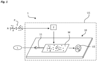
- the invention relates to a collection membrane M intended to be used in an electrostatic collector 1 of airborne particles P.
- P particles can be micro-particles or nano-particles present in the air in the form of aerosols.
- the collection of particles P can in particular be carried out in the ambient air or in the air exhaled by a living being. In the rest of the description, it will be considered that the collection of the particles is carried out in the ambient air.
- One of the objectives is to analyze the P particles with a view to detecting the presence of a pathogenic agent or a trace of its presence, by analyzing the particles collected.
- the pathogens sought may be, inter alia, microorganisms such as viruses, bacteria, fungal spores, or toxins, mycotoxins, allergens, or any other harmful agent.
- the particles are advantageously collected for the purpose of analysis.
- the analysis can consist of detecting the presence of DNA, RNA, proteins, elements that make up the pathogen, such as lipids or carbohydrates, one or more pathogens present in the collected particles.
- the analysis can also consist in detecting molecules such as ATP or even sugars such as mannitol, arabitol and glucose which provide information on the presence of microorganisms.
- the analysis can also relate to the detection of molecules such as allergens and mycotoxins.
- the method of analysis can be of the biomolecular amplification type (for example of the LAMP, RPA, PCR type, etc.) or of the immunoenzymatic type (for example of the ELISA type).
- the collector may in particular be employed in the form of a monitoring beacon. For this, it will then have to have a certain operating autonomy, that is to say be able to collect and analyze the particles, with a minimum of external intervention and in particular without manipulation between the collection phase and the analysis phase.
- FIG. 1 illustrates the operating principle of an electrostatic collector 1 employing a collection membrane M such as that of the invention.
- the collector can incorporate a particle collection unit U1 and an analysis unit U2 of the collected particles.
- the architecture described below and represented on the figure 1 should be considered in a non-restrictive manner.
- the particle collection unit U1 comprises a main collection component.
- the collection component 10 can be made of a material of the COP/COC (Cyclo Olefin Polymer/Cyclo Olefin Copolymer) type, polycarbonate or of the PMMA (Polymethyl methacrylate) type.
- COP/COC Cyclo Olefin Polymer/Cyclo Olefin Copolymer
- PMMA Polymethyl methacrylate
- it may present transparency characteristics, sufficient for optical reading when the analysis is implemented directly in the analysis unit U2 of the component 10.
- Component 10 operates by electrostatic effect. It comprises two electrodes, a discharge electrode and a so-called collection counter-electrode, which is generally connected to ground.
- the two electrodes are each connected to a separate terminal of an electrical power source and are separated from each other so as to create an electrostatic field sufficient to attract airborne particles towards the collection electrode, in order to be picked up and trapped at this collection electrode.
- the collection electrode is formed by the collection membrane M of the invention.
- the collection unit U1 is arranged on a dedicated wall of the component 10 and carries the collection membrane M of the invention, with a view to collecting the particles P.
- the component 10 may in particular comprise a chamber into which is injected or sucked a flow of air containing the particles.
- Collection means 2 which can be generators of the air flow, are configured to direct the particles present in the air towards the collection membrane M.
- the component 10 may in particular comprise an internal collection channel through which the air to be analyzed circulates. Air circulation through the channel can be forced (for example using a fan) or not.
- the collection membrane M is arranged to at least partially line the internal surface of the collection channel, so that the particles present in the air flow injected into the channel can be exposed to the electrostatic field created.
- the component 10 can advantageously integrate a fluidic circuit, called fluidic elution circuit.
- This fluidic elution circuit advantageously comprises a first fluidic channel 11 opening towards the collection membrane M, in order to be able to pour the elution liquid L onto the membrane.
- the fluidic elution circuit can also comprise a receptacle for receiving the elution liquid L drained by the membrane M and transporting the particles P.
- the elution liquid L is for example water.
- the liquid L ensures the wetting of the entire surface of the membrane M and carries with it the particles previously collected.
- the analysis unit U2 of the P particles collected can be installed in the component 10 used for the collection, as presented on the figure 1 , or be separated from it. It is advantageously installed in the component 10 to reduce the material that an operator would have to handle and to make it possible to automate the process.
- Analysis unit U2 may comprise a detection chamber made in component 10 and intended to receive the sample collected after elution. This detection chamber can be formed directly from the receptacle for recovering the liquid L after elution. This detection chamber can carry the reagents necessary for the analysis, for example to implement a biomolecular amplification reaction.
- the analysis can be carried out by biomolecular amplification or be of the immunoenzymatic type (ELISA type) or else of the immunochromatographic type (LFA type).
- ELISA type immunoenzymatic type
- LFA type immunochromatographic type
- the membrane M is also designed with materials compatible with the analysis reactions that can be implemented and listed above.
- membrane is meant a strip composed of one or more layers of material having a small thickness (a few micrometers to a few millimeters) with regard to its length and its width.
- hydrophilic character it is meant that the hydrophilic layer advantageously has a contact angle of less than 75° after a very short period of less than a few seconds, for example 5 seconds. Furthermore, in the collection zone of the membrane, this contact angle then decreases very rapidly until it is less than 50°, the water penetrating very rapidly into the material. It therefore has a very hydrophilic character.
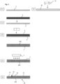
- Step E1 The hydrophilic layer 3 is used as a support for the matrix 40 in the manufacturing process.
- the hydrophilic layer 3 advantageously comprises interlaced fibers, said fibers defining interstices between them through which the liquid can flow during elution.
- the hydrophilic layer 3 can be made of a fibrous or cellular material, which can drain a liquid such as water.
- it can be made of a material based on cellulose (for example filter paper or the like), in a material of the hydrophilic type fabric, of the foam type (sponge) or of the fiberglass type.
- the hydrophilic layer 3 is for example composed of Whatman type paper (registered trademark).
- the thickness of the membrane is chosen so as to retain by capillarity a volume of less than 30 ⁇ l/cm 2 .
- Step E2 A second layer 4 is manufactured.
- This second layer 4 is composed of a mixture of a matrix 40 made of polymer material and a filler 41 made of an electrically conductive material.
- the filler 41 is added to the matrix in order to give the membrane its conductive character.
- the matrix 40 can be made from silicone and the filler 41 can be carbon powder.
- Carbon and silicone as well as the carbon/silicone pair have the advantage of being inert with respect to biochemical reactions.
- the composite material formed is therefore not capable of inhibiting these reactions.
- other materials having such properties vis-à-vis biochemical reactions could be considered.
- the carbon in graphite form is added to the silicone matrix in a percentage by mass of between 30% and 50%.
- the filler concentration must be chosen sufficient to obtain good electrical conductivity, without reducing the mechanical strength of the material obtained and in particular the trapping of the powder incorporated by the matrix (for example based on silicone).
- This second layer has a liquid, pasty and viscous form, facilitating its shaping and its deposition before polymerization.
- Step E3 The second layer 4 is deposited on the hydrophilic layer 3, for example formed from paper (see above). It should be noted that the hydrophilic layer 3 is advantageously chosen with a sufficiently rough and/or porous surface, in order to better grip the mixture.
- the second layer 4 is deposited on the first layer 3 at a constant thickness over the whole of the first layer 3.
- Step E4 The multilayer assembly is then placed under conditions for polymerization of the matrix (T°).
- T° the matrix
- the multilayer assembly can be heated to 60° C. for 3 hours.
- the second layer 4 impregnates the hydrophilic layer 3, forming the composite material 400.
- a thin hydrophilic layer 3 remains on the surface.
- the membrane M can be used as it is in a collector.
- Layer 3, which is hydrophilic is placed in the collector in contact with the air and on the path of the air flow, and therefore on the path of the particles P to be collected.
- the particles will be attracted by the polarized conductive layer 4 and will be deposited on the hydrophilic layer 3 of the membrane M on which they will be captured, possibly inside the first layer if the latter has sufficient porosity.
- the hydrophilic layer 3 has a three-dimensional structure (thus forming cells and a sufficiently porous layer), such as for example paper, the liquid L for eluting the particles P collected will penetrate the entire thickness of the hydrophilic layer 3. This "volume capillarity" is much more efficient in guiding the liquid L throughout the medium. All of the captured particles P are then entrained by the elution liquid L, increasing the elution yield. The liquid carrying the particles can be recovered in a dedicated receptacle placed downstream.
- the elution liquid L is advantageously water. It may advantageously contain a surfactant such as for example TritonX100 and proteins such as for example BSA or casein to increase the wetting of the membrane, block the protein/surface interactions and increase the yield of recovery of the collected particles.
- a surfactant such as for example TritonX100 and proteins such as for example BSA or casein to increase the wetting of the membrane, block the protein/surface interactions and increase the yield of recovery of the collected particles.
- a manufacturing step of the membrane M consists in creating one or more zones on the membrane, by treatment of the hydrophilic layer.
- Step E5 The surface treatment can consist of etching the hydrophilic layer 3 still present (etching means 5), for example by laser etching, milling or even by creating zones using barriers made for example of paraffin .
- the etching operations can be carried out over a greater or lesser thickness than the total thickness of the hydrophilic layer, in order to be able to define one or more zones.
- the different zones can be produced on the same membrane M and occupy all or part of the total surface of the membrane M.
- the collection zone Z1 can in particular be more or less extensive.
- the collection zone Z1 is obtained by etching on a thickness of the hydrophilic layer 3, less than its total thickness, with a view to obtaining a zone having a compromise between characteristics of wettability and quality of capture of the particles P by electrostatic forces.
- the wetting zone Z2 is the zone through which the elution liquid L is introduced for the recovery of the particles P collected. It makes it possible to ensure the distribution of the elution front over the entire width of the membrane, avoiding preferential flow paths, and a regular flow of the elution liquid L.
- the liquid L introduced by the zone of wetting Z2 ensures the wetting of the entire surface of the membrane M, at least at the level of its collection zone Z1, and carries with it the particles previously collected.
- the liquid L carries the particles P and is advantageously recovered in a dedicated receptacle.
- the contact recovery zone Z3 can also be used as a confinement zone for the elution liquid L, the second layer 4 being hydrophobic.
- Each barrier zone Z4 can be formed by depositing a layer of paraffin on the surface of the membrane M.
- a barrier zone is configured to form a barrier to the liquid L between two distinct zones of the membrane.
- the hydrophilic layer can be treated with a solution composed of a sugar such as lactose, trehalose or else sucrose which, by dissolving during elution, facilitates the entrainment of the particles collected by the elution liquid L.
- a sugar such as lactose, trehalose or else sucrose which, by dissolving during elution, facilitates the entrainment of the particles collected by the elution liquid L.
- the final membrane M obtained can be cut to the desired dimensions, in order to adapt to the geometry of the electrostatic collector.
- FIG. 3 shows a first embodiment in which the collection membrane M is in the form of a sock.
- the membrane M does not include the end zone Z5.
- the other zones Z1 to Z4 are produced on the membrane in the manner described above.
- FIG 4 shows another exemplary embodiment, in which the collection membrane M has an elongated shape along a longitudinal axis.
- the different zones are juxtaposed along the axis of the membrane.
- the membrane M is configured in such a way as to present the zone Z3 at a first end. This is extended by zone Z4 forming the barrier zone.
- Zone Z4 is extended by zone Z2, which corresponds to the zone for wetting and introducing the elution liquid.
- Zone Z2 is extended by zone Z1 which is intended for the collection of particles.
- the membrane ends at its other end with zone Z5.
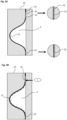
- FIG. 5A illustrates the principle of positioning the collection membrane M in its housing. It is thus held between two plates of the component 10, and at least partially lines the cross section of the collection channel 6 formed by the assembly of the two plates.
- the membrane is held by compression on one side at its zones Z3, Z4 and Z2 and on the opposite side by its zone Z5.
- the collection zone Z1 is then arranged to fit around a recessed surface of the channel 6.
- zone Z2 and zone Z5 At the level of zone Z2 and zone Z5, through which the liquid is caused to circulate, the compression is partial so as not to block the flow, while forming an obstacle which forces the flowing liquid to pass through these two migration zones in the form of a film of an imposed thickness.
- This configuration avoids any risk of runoff along preferential paths, in particular at the inlet (in zone Z2), where the liquid arrives under pressure.
- zones Z2 and Z5 also provide mechanical robustness by placing the membrane in the correct position, where the ends tend to lift relative to the component.
- FIG. 5B illustrates the principle of liquid flow in the membrane, during the elution of the collected particles. It can be seen that the adjusted compression of the membrane at the level of the Z2 zone helps to create a capillary film up to the Z5 zone. The suitable compression of the Z5 zone makes it possible to create a regular flow at the outlet, and to avoid the formation of drops.
Landscapes
- Health & Medical Sciences (AREA)
- Life Sciences & Earth Sciences (AREA)
- Pathology (AREA)
- General Health & Medical Sciences (AREA)
- Immunology (AREA)
- Physics & Mathematics (AREA)
- Chemical & Material Sciences (AREA)
- Analytical Chemistry (AREA)
- Biochemistry (AREA)
- General Physics & Mathematics (AREA)
- Biomedical Technology (AREA)
- Molecular Biology (AREA)
- Engineering & Computer Science (AREA)
- Sampling And Sample Adjustment (AREA)
- Separation Using Semi-Permeable Membranes (AREA)
- Laminated Bodies (AREA)
Applications Claiming Priority (1)
| Application Number | Priority Date | Filing Date | Title |
|---|---|---|---|
| FR2113751A FR3130649A1 (fr) | 2021-12-17 | 2021-12-17 | Membrane de collecte de particules aéroportées |
Publications (1)
| Publication Number | Publication Date |
|---|---|
| EP4197641A1 true EP4197641A1 (de) | 2023-06-21 |
Family
ID=80448643
Family Applications (1)
| Application Number | Title | Priority Date | Filing Date |
|---|---|---|---|
| EP22211236.9A Pending EP4197641A1 (de) | 2021-12-17 | 2022-12-02 | Membran zur sammlung von luftpartikeln |
Country Status (3)
| Country | Link |
|---|---|
| US (1) | US20230191426A1 (de) |
| EP (1) | EP4197641A1 (de) |
| FR (1) | FR3130649A1 (de) |
Citations (10)
| Publication number | Priority date | Publication date | Assignee | Title |
|---|---|---|---|---|
| US20010021534A1 (en) * | 1995-03-10 | 2001-09-13 | Meso Scale Technologies, Llc | Multi-array, multi-specific electrochemiluminescence testing |
| US20040083790A1 (en) | 2002-11-04 | 2004-05-06 | Carlson Duane C. | Portable liquid collection electrostatic precipitator |
| US20050072917A1 (en) * | 2003-09-30 | 2005-04-07 | Thomas Becker | Methods of making substrates for mass spectrometry analysis and related devices |
| WO2007012447A1 (fr) | 2005-07-28 | 2007-02-01 | Commissariat A L'energie Atomique (Cea) | Dispositif d' extraction air/eau par collection electrostatique semi-humide et procede utilisant ce dispositif |
| EP1112124B1 (de) | 1998-06-17 | 2007-03-14 | Ohio University | Elektroabscheider mit membran |
| EP1814137A2 (de) * | 2006-01-27 | 2007-08-01 | Sony DADC Austria AG | Probenhalteranordnung für Mass Spektrometrie |
| US20100000540A1 (en) | 2008-04-11 | 2010-01-07 | Patrick Pouteau | Device for extracting particles from exhaled breath |
| WO2015085054A1 (en) * | 2013-12-04 | 2015-06-11 | Ohio University | Bidirectional rapping apparatus for electrostatic precipitator electrodes |
| WO2015197747A1 (fr) | 2014-06-25 | 2015-12-30 | Commissariat à l'énergie atomique et aux énergies alternatives | Collecteur electrostatique |
| EP4015087A1 (de) | 2020-12-21 | 2022-06-22 | Commissariat à l'énergie atomique et aux énergies alternatives | Gerät zum sammeln und analysieren von schwebeteilchen in der luft |
Family Cites Families (1)
| Publication number | Priority date | Publication date | Assignee | Title |
|---|---|---|---|---|
| GB1271506A (en) | 1968-07-26 | 1972-04-19 | British Petroleum Co | Improvements in or relating to fermenters |
-
2021
- 2021-12-17 FR FR2113751A patent/FR3130649A1/fr active Pending
-
2022
- 2022-12-02 EP EP22211236.9A patent/EP4197641A1/de active Pending
- 2022-12-13 US US18/064,986 patent/US20230191426A1/en active Pending
Patent Citations (12)
| Publication number | Priority date | Publication date | Assignee | Title |
|---|---|---|---|---|
| US20010021534A1 (en) * | 1995-03-10 | 2001-09-13 | Meso Scale Technologies, Llc | Multi-array, multi-specific electrochemiluminescence testing |
| EP1112124B1 (de) | 1998-06-17 | 2007-03-14 | Ohio University | Elektroabscheider mit membran |
| US20040083790A1 (en) | 2002-11-04 | 2004-05-06 | Carlson Duane C. | Portable liquid collection electrostatic precipitator |
| WO2004041440A1 (en) | 2002-11-04 | 2004-05-21 | Westinghouse Savannah River Company, Llc | Portable liquid collection electrostatic precipitator |
| US20050072917A1 (en) * | 2003-09-30 | 2005-04-07 | Thomas Becker | Methods of making substrates for mass spectrometry analysis and related devices |
| WO2007012447A1 (fr) | 2005-07-28 | 2007-02-01 | Commissariat A L'energie Atomique (Cea) | Dispositif d' extraction air/eau par collection electrostatique semi-humide et procede utilisant ce dispositif |
| US20080295687A1 (en) | 2005-07-28 | 2008-12-04 | Ernest Galbrun | Device for Air/Water Extraction by Semi-Humid Electrostatic Collection and Method Using Same |
| EP1814137A2 (de) * | 2006-01-27 | 2007-08-01 | Sony DADC Austria AG | Probenhalteranordnung für Mass Spektrometrie |
| US20100000540A1 (en) | 2008-04-11 | 2010-01-07 | Patrick Pouteau | Device for extracting particles from exhaled breath |
| WO2015085054A1 (en) * | 2013-12-04 | 2015-06-11 | Ohio University | Bidirectional rapping apparatus for electrostatic precipitator electrodes |
| WO2015197747A1 (fr) | 2014-06-25 | 2015-12-30 | Commissariat à l'énergie atomique et aux énergies alternatives | Collecteur electrostatique |
| EP4015087A1 (de) | 2020-12-21 | 2022-06-22 | Commissariat à l'énergie atomique et aux énergies alternatives | Gerät zum sammeln und analysieren von schwebeteilchen in der luft |
Non-Patent Citations (2)
| Title |
|---|
| HYEONG RAE KIMSANGGWON ANJUNGHO HWANG: "Aerosol-to-Hydrosol Sampling and Simultaneous Enrichment of Airborne Bacteria For Rapid Biosensing", ACS SENS., vol. 5, 2020, pages 2763 - 2771, XP055836553, DOI: 10.1021/acssensors.0c00555 |
| J-M. ROUXA. RONGIERD. JARY: "Importance of the substrate nature to preserve microorganisms' cultivability in electrostatic air samplers", JOURNAL OF PHYSICS: CONFÉRENCE SERIES, vol. 646, no. 1, 2015, pages 012039, XP020290002, DOI: 10.1088/1742-6596/646/1/012039 |
Also Published As
| Publication number | Publication date |
|---|---|
| FR3130649A1 (fr) | 2023-06-23 |
| US20230191426A1 (en) | 2023-06-22 |
Similar Documents
| Publication | Publication Date | Title |
|---|---|---|
| EP1919626B1 (de) | Vorrichtung zur luft-/wasser-extraktion durch halbfeuchtes elektrostatisches auffangen und verwendungsverfahren dafür | |
| EP4015087A1 (de) | Gerät zum sammeln und analysieren von schwebeteilchen in der luft | |
| EP2108456B1 (de) | Extraktionsvorrichtung von Partikeln aus verbrauchter Atemluft | |
| EP3629000B1 (de) | Verfahren zur präparation einer biologischen probe | |
| FR2884437A1 (fr) | Dispositif et procede microfluidique de transfert de matiere entre deux phases immiscibles. | |
| FR2923151A1 (fr) | Dispositif de prelevement sanguin comportant au moins un filtre . | |
| WO2015071597A2 (fr) | Nouveau milieu filtrant pour l'obtention de plasma, dispositif et procédé de filtration associés | |
| EP3036546B1 (de) | Mikrofluidisches system und verfahren zur isolierung und quantifizierung von mindestens einer subpopulation von zellen aus einer zellpopulation | |
| CA2756098C (fr) | Procede de detection et de quantification d'analytes d'interet dans un liquide et dispositif de mise en oeuvre | |
| FR3049061A1 (fr) | Dispositif d'analyse d'un echantillon biologique | |
| EP3149445A1 (de) | Vorrichtung zur lysierung biologischer spezies und durch die besagte vorrichtung implementiertes verfahren | |
| EP1889053A2 (de) | Planare vorrichtung mit durch dynamische elektrobenetzung automatisierter well-adressierung | |
| EP1711955A1 (de) | Labor auf einem chip mit koplanarem mikrofluidischem system und elektrospray-düse | |
| EP4197641A1 (de) | Membran zur sammlung von luftpartikeln | |
| FR2887705A1 (fr) | Dispositif de pompage ou de centrifugation des gouttes deplacees par electromouillage | |
| EP2153899A1 (de) | Labor auf Chip, das ein koplanares mikrofluidisches Netzwerk und einen koplanaren elektrischen Zerstäuberkopf umfasst | |
| EP4385623A1 (de) | Oberflächenfunktionalisierte luftpartikelsammelmembran | |
| WO2019073006A1 (fr) | Methode et dispositif de tri de fibres en suspension dans un aerosol par la combinaison de forces electrostatiques et de gravite | |
| EP3013477B1 (de) | Vorrichtung zur trennung einer suspension | |
| EP3654011B1 (de) | Präparationsverfahren einer zu analysierenden probe, die aus einer lebensmittelmatrix erhalten wurde | |
| EP3694649B1 (de) | Verfahren und vorrichtung zum sortieren von in einem aerosol suspendierten fasern unter verwendung kombinierter elektrostatischer und zentrifugaler kräfte | |
| EP3593132B1 (de) | Träger für eine probe einer biologischen spezies | |
| FR2723541A1 (fr) | Procede de fabrication de structures minerales filtrantes | |
| JP2515762B2 (ja) | 微量遠心分離用セル | |
| FR2983093A1 (fr) | Dispositif de collecte electrostatique de particules en suspension dans un milieu gazeux |
Legal Events
| Date | Code | Title | Description |
|---|---|---|---|
| PUAI | Public reference made under article 153(3) epc to a published international application that has entered the european phase |
Free format text: ORIGINAL CODE: 0009012 |
|
| STAA | Information on the status of an ep patent application or granted ep patent |
Free format text: STATUS: REQUEST FOR EXAMINATION WAS MADE |
|
| 17P | Request for examination filed |
Effective date: 20221202 |
|
| AK | Designated contracting states |
Kind code of ref document: A1 Designated state(s): AL AT BE BG CH CY CZ DE DK EE ES FI FR GB GR HR HU IE IS IT LI LT LU LV MC ME MK MT NL NO PL PT RO RS SE SI SK SM TR |
|
| RAP3 | Party data changed (applicant data changed or rights of an application transferred) |
Owner name: COMMISSARIAT A L'ENERGIE ATOMIQUE ET AUX ENERGIESALTERNATIVES |