EP4196805B1 - Batteriemanagementsystem zum klassifizieren eines batteriemoduls - Google Patents
Batteriemanagementsystem zum klassifizieren eines batteriemoduls Download PDFInfo
- Publication number
- EP4196805B1 EP4196805B1 EP21749774.2A EP21749774A EP4196805B1 EP 4196805 B1 EP4196805 B1 EP 4196805B1 EP 21749774 A EP21749774 A EP 21749774A EP 4196805 B1 EP4196805 B1 EP 4196805B1
- Authority
- EP
- European Patent Office
- Prior art keywords
- voltage curve
- voltage
- electrical characteristic
- battery
- segment
- Prior art date
- Legal status (The legal status is an assumption and is not a legal conclusion. Google has not performed a legal analysis and makes no representation as to the accuracy of the status listed.)
- Active
Links
Images


Classifications
-
- G—PHYSICS
- G01—MEASURING; TESTING
- G01R—MEASURING ELECTRIC VARIABLES; MEASURING MAGNETIC VARIABLES
- G01R31/00—Arrangements for testing electric properties; Arrangements for locating electric faults; Arrangements for electrical testing characterised by what is being tested not provided for elsewhere
- G01R31/36—Arrangements for testing, measuring or monitoring the electrical condition of accumulators or electric batteries, e.g. capacity or state of charge [SoC]
- G01R31/392—Determining battery ageing or deterioration, e.g. state of health
-
- G—PHYSICS
- G01—MEASURING; TESTING
- G01R—MEASURING ELECTRIC VARIABLES; MEASURING MAGNETIC VARIABLES
- G01R31/00—Arrangements for testing electric properties; Arrangements for locating electric faults; Arrangements for electrical testing characterised by what is being tested not provided for elsewhere
- G01R31/36—Arrangements for testing, measuring or monitoring the electrical condition of accumulators or electric batteries, e.g. capacity or state of charge [SoC]
- G01R31/367—Software therefor, e.g. for battery testing using modelling or look-up tables
-
- G—PHYSICS
- G01—MEASURING; TESTING
- G01R—MEASURING ELECTRIC VARIABLES; MEASURING MAGNETIC VARIABLES
- G01R31/00—Arrangements for testing electric properties; Arrangements for locating electric faults; Arrangements for electrical testing characterised by what is being tested not provided for elsewhere
- G01R31/36—Arrangements for testing, measuring or monitoring the electrical condition of accumulators or electric batteries, e.g. capacity or state of charge [SoC]
- G01R31/382—Arrangements for monitoring battery or accumulator variables, e.g. SoC
- G01R31/3835—Arrangements for monitoring battery or accumulator variables, e.g. SoC involving only voltage measurements
-
- G—PHYSICS
- G01—MEASURING; TESTING
- G01R—MEASURING ELECTRIC VARIABLES; MEASURING MAGNETIC VARIABLES
- G01R31/00—Arrangements for testing electric properties; Arrangements for locating electric faults; Arrangements for electrical testing characterised by what is being tested not provided for elsewhere
- G01R31/36—Arrangements for testing, measuring or monitoring the electrical condition of accumulators or electric batteries, e.g. capacity or state of charge [SoC]
- G01R31/396—Acquisition or processing of data for testing or for monitoring individual cells or groups of cells within a battery
Definitions
- the invention relates to a battery management system and a method for classifying a battery module with battery cells.
- the invention relates to classification algorithms for automatically detecting anomalies in the battery module.
- the publication US 2016/169978 A1 relates to an apparatus, a method and a non-volatile recording medium storing a program for identifying a position of an abnormality that has occurred in a secondary battery system having two or more modules, each housing one or more blocks. Each of the blocks is formed by connecting battery cells from two or more secondary batteries.
- the publication US 6 526 361 B1 describes a method and apparatus for battery evaluation and classification, whereby transient micro-charge and/or micro-load pulses are applied to an automotive battery. Classification is performed based on analysis of the resulting voltage profile or portions or dimensions thereof.
- machine learning methods are suitable for detecting anomalies in battery systems.
- the invention is based on the idea that the anomalies are visible based on the voltage curves of the battery modules.
- the effects of faulty internal resistance values, capacity values and offset voltages are derived from the electrical circuitry of a battery model. It turned out that all observed effects can be described using the three physical quantities mentioned. On the basis of this knowledge, various types of anomalies and a normal case are defined.
- the object is achieved by a battery management system for classifying a battery module, wherein the battery module has a first battery cell and a second battery cell.
- the battery management system comprises an interface and a processor.
- the interface is designed to receive a first voltage curve across the first battery cell and a second voltage curve across the second battery cell, wherein the first voltage curve has a first voltage curve section and a second voltage curve section, and wherein the second voltage curve has a third voltage curve section and a fourth voltage curve section.
- the processor is designed to: determine a reference voltage curve based on an average voltage value from the first voltage curve and from the second voltage curve, the reference voltage curve having a first reference voltage curve section and a second reference voltage curve section; compare the first voltage curve with the reference voltage curve to obtain a first metric indicating a first voltage deviation between the first voltage curve section and the first reference voltage curve section and a second voltage deviation between the second voltage curve section and the second reference voltage curve section; compare the second voltage curve with the reference voltage curve to obtain a second metric indicating a third voltage deviation between the third voltage curve section and the first reference voltage curve section and a fourth voltage deviation between the fourth voltage curve section and the second reference voltage curve section; assign a first electrical characteristic to the first voltage waveform section and assign a second electrical characteristic to the second voltage waveform section if the first metric is greater than the second metric to classify the battery module by the first electrical characteristic and the second electrical characteristic; or assign a third electrical characteristic to the third voltage waveform section and assign a fourth electrical characteristic to the fourth voltage waveform section if
- the battery management system comprises a memory which is designed to store a plurality of electrical characteristics, wherein the processor is designed to read the respective electrical characteristic from the memory.
- the processor is configured to determine the reference voltage curve on the basis of the first voltage curve and the second voltage curve.
- This provides the technical advantage that a reference voltage curve for a battery module is efficiently calculated.
- the reference voltage curve comprises a median or an average of the first voltage curve and the second voltage curve.
- This provides the technical advantage that a reference voltage curve for a battery module is efficiently calculated.
- the battery module has a third battery cell and the interface is designed to obtain a third voltage curve across the third battery cell, wherein the processor is designed to determine the reference voltage curve on the basis of the first voltage curve, the second voltage curve and the third voltage curve.
- the reference voltage curve comprises a median, an average or a mode from the first voltage curve, the second voltage curve and the third voltage curve.
- the processor is designed to: determine the first electrical characteristic on the basis of the first voltage curve section of the first voltage curve and the second electrical characteristic on the basis of the second voltage curve section of the first voltage curve by means of a principal component analysis, wherein the first electrical characteristic represents the first voltage curve section of the first voltage curve and the second electrical characteristic represents the second voltage curve section of the first voltage curve; and/or determine the third electrical characteristic on the basis of the third voltage curve section of the second voltage curve and the fourth electrical characteristic on the basis of the fourth voltage curve section of the second voltage curve by means of the principal component analysis, wherein the third electrical characteristic represents the third voltage curve section of the second voltage curve and the fourth electrical characteristic represents the fourth voltage curve section of the second voltage curve.
- the processor is configured to determine a first electrical feature based on the first voltage waveform section of the first voltage waveform, a second electrical feature based on the second voltage waveform section of the first voltage waveform, a third electrical feature based on the third voltage waveform section of the second voltage waveform, a fourth electrical feature based on the fourth voltage waveform section of the second voltage waveform.
- the first electrical feature corresponds to an offset voltage of the first battery cell and the third electrical feature corresponds to a further offset voltage of the second battery cell, wherein the second electrical feature corresponds to an internal resistance of the first battery cell and the fourth electrical feature corresponds to a further internal resistance of the second battery cell.
- the processor is configured to classify the battery module using a classification algorithm, wherein the classification algorithm comprises at least one of logistic regression, support vector machine, random forest, multi-layer perceptron, and one-class support vector machine.
- This provides the technical advantage of efficiently classifying a battery module to determine whether the battery module is fault-free or faulty.
- the interface is designed to receive a first plurality of voltage waveforms and a second plurality of voltage waveforms, wherein each of the first plurality of voltage waveforms corresponds to a first battery cell of one of a plurality of battery modules and each of the second plurality of voltage waveforms corresponds to a second battery cell of one of the plurality of battery modules, wherein the interface is designed to handle the plurality of battery modules as fault-free, wherein the processor is designed to classify each battery module of the plurality of battery modules by means of a further classification algorithm in order to form a reference group on the basis of the classification.
- This provides the technical advantage of efficiently forming a reference group of fault-free battery modules and setting a strict limit for fault-free battery modules in the feature space is defined, allowing battery modules that lie outside this boundary to be declared as anomalies.
- the processor is configured to classify the plurality of battery modules by means of a further classification algorithm, wherein the further classification algorithm comprises at least one of logistic regression, support vector machine, random forest, multi-layer perceptron, and one-class support vector machine.
- the first voltage waveform has a fifth voltage waveform section and the second voltage waveform has a sixth voltage waveform section, wherein the processor is configured to extract a fifth feature based on the fifth voltage waveform section of the first voltage waveform and a sixth feature based on the sixth voltage waveform section of the second voltage waveform.
- the fifth feature corresponds to a capacity of the first battery cell and the sixth feature corresponds to a further capacity of the second battery cell.
- the interface is designed to receive a number of groups to be generated, a further first plurality of voltage curves and a further second plurality of voltage curves, wherein each of the further first plurality of voltage curves corresponds to a first battery cell of a further plurality of battery modules and wherein each the further second plurality of voltage curves of a second battery cell of one of the further plurality of battery modules, wherein the processor is designed to assign each battery module of the further plurality of battery modules to a plurality of groups by means of the classification algorithm, wherein the set of the plurality of groups is equal to the number of groups to be generated.
- the object is achieved according to a second aspect of the invention by a method for battery management, comprising the following method steps: Obtaining a first voltage curve across a first battery cell of a battery module and a second voltage curve across a second battery cell of the battery module, wherein the first voltage curve has a first voltage curve section and a second voltage curve section, and wherein the second voltage curve has a third voltage curve section and a fourth voltage curve section; Determining a reference voltage curve based on an average voltage from the first voltage curve and from the second voltage curve, wherein the reference voltage curve has a first reference voltage curve section and a second reference voltage curve section; Comparing the first voltage curve with the reference voltage curve to obtain a first metric which indicates a first voltage deviation between the first voltage curve section and the first reference voltage curve section and a second voltage deviation between the second voltage curve section and the second reference voltage curve section; Comparing the second voltage waveform with the reference voltage waveform to obtain a second metric indicating a third voltage deviation between the third voltage waveform section and the first reference voltage wave
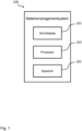
- Fig.1 shows a schematic representation of a battery management system 100 for classifying a battery module according to an embodiment, wherein the battery module has at least a first battery cell and a second battery cell.
- the battery management system 100 comprises an interface 101, a processor 103 and a memory 105, the functionalities of which are examined in more detail below.
- the interface 101 is configured to obtain a first voltage curve across the first battery cell and a second voltage curve across the second battery cell, wherein the first voltage curve has a first voltage curve section and a second voltage curve section, and wherein the second voltage curve has a third voltage curve section and a fourth voltage curve section.
- the processor 103 is configured to determine a reference voltage curve based on a voltage average from the first voltage curve and from the second voltage curve, the reference voltage curve having a first reference voltage curve section and a second reference voltage curve section.
- the processor 105 is configured to determine the reference voltage curve based on the first voltage curve and the second voltage curve, and the reference voltage curve comprises a median or an average of the first voltage curve and the second voltage curve.
- the processor 103 is configured to compare the first voltage waveform with the reference voltage waveform to obtain a first metric indicating a first voltage deviation between the first voltage waveform section and the first reference voltage waveform section and a second voltage deviation between the second voltage waveform section and the second reference voltage waveform section; and to compare the second voltage waveform with the reference voltage waveform to obtain a second metric indicating a third voltage deviation between the third voltage waveform section and the first reference voltage waveform section and a fourth voltage deviation between the fourth voltage waveform section and the second reference voltage waveform section.
- the processor 103 is configured to assign a first electrical characteristic to the first voltage waveform section and to assign a second electrical characteristic to the second voltage waveform section in order to classify the battery module by the first electrical characteristic and the second electrical characteristic.
- the processor 103 is configured to: determine the first electrical characteristic based on the first voltage waveform section of the first voltage waveform and the second electrical characteristic based on the second voltage waveform section of the first voltage waveform by means of a principal component analysis, wherein the first electrical characteristic represents the first voltage waveform section of the first voltage waveform and the second electrical characteristic represents the second voltage waveform section of the first voltage waveform.
- the processor 103 is configured to assign a third electrical characteristic to the third voltage waveform section and to assign a fourth electrical characteristic to the fourth voltage waveform section if the first metric is smaller than the second metric to classify the battery module by the third electrical characteristic and the fourth electrical characteristic.
- the processor 103 is configured to determine the third electrical characteristic based on the third voltage waveform section of the second voltage waveform and the fourth electrical characteristic based on the fourth voltage waveform section of the second voltage waveform by means of the principal component analysis, wherein the third electrical characteristic represents the third voltage waveform section of the second voltage waveform and the fourth electrical characteristic represents the fourth voltage waveform section of the second voltage waveform.
- the memory 105 is configured to store a plurality of electrical characteristics, wherein the processor 103 is configured to read the respective electrical characteristic from the memory.
- the processor 103 is configured to classify the battery module using a classification algorithm, wherein the classification algorithm comprises at least one of logistic regression, support vector machine, random forest, multi-layer perceptron, and one-class support vector machine.
- the battery module further comprises a third battery cell and the interface 101 is designed to obtain a third voltage curve across the third battery cell, wherein the processor 103 is designed to obtain the reference voltage curve based on the first voltage waveform, the second voltage waveform and the third voltage waveform.
- the reference voltage waveform comprises a median, an average or a mode of the first voltage waveform, the second voltage waveform and the third voltage waveform.
- the processor is configured to determine a first electrical feature based on the first voltage waveform section of the first voltage waveform, a second electrical feature based on the second voltage waveform section of the first voltage waveform, a third electrical feature based on the third voltage waveform section of the second voltage waveform, a fourth electrical feature based on the fourth voltage waveform section of the second voltage waveform, wherein the first electrical feature corresponds to an offset voltage of the first battery cell and the third electrical feature corresponds to a further offset voltage of the second battery cell, wherein the second electrical feature corresponds to an internal resistance of the first battery cell and the fourth electrical feature corresponds to a further internal resistance of the second battery cell.
- the interface 101 is configured to receive a first plurality of voltage waveforms and a second plurality of voltage waveforms, wherein each of the first plurality of voltage waveforms corresponds to a first battery cell of one of a plurality of battery modules and each of the second plurality of voltage waveforms corresponds to a second battery cell of one of the plurality of battery modules, wherein the interface is configured to handle the plurality of battery modules as fault-free.
- the processor 103 is configured to classify each battery module of the plurality of battery modules by means of a further classification algorithm in order to form a reference group on the basis of the classification, wherein the further classification algorithm comprises at least one of logistic regression, support vector machine, random forest, multi-layer perceptron, one-class support vector machine.
- the first voltage waveform has a fifth voltage waveform section and the second voltage waveform has a sixth voltage waveform section, wherein the processor 103 is configured to detect a fifth feature on the Based on the fifth voltage waveform section of the first voltage waveform and a sixth feature based on the sixth voltage waveform section of the second voltage waveform.
- the fifth feature corresponds to a capacity of the first battery cell and the sixth feature corresponds to a further capacity of the second battery cell.
- the interface 101 is further configured to receive a number of groups to be generated, a further first plurality of voltage waveforms and a further second plurality of voltage waveforms, wherein each of the further first plurality of voltage waveforms corresponds to a first battery cell of one of a further plurality of battery modules and wherein each of the further second plurality of voltage waveforms corresponds to a second battery cell of one of the further plurality of battery modules.
- the processor 103 is configured to assign each battery module of the further plurality of battery modules to a plurality of groups by means of the classification algorithm, wherein the set of the plurality of groups is equal to the number of groups to be generated.
- battery modules can be fully automatically analyzed with regard to their behavior and possible anomalies can be detected and categorized.
- the embodiments of the present invention relate to the following aspects: battery simulation, outlier detection and feature extraction, classification algorithms and anomaly detection, which are discussed in more detail below.
- a classification model assigns each module to a known group (categorizes it), with a downstream anomaly detector examining the decision as to whether it is an anomaly even more critically. However, in these cases, a purely binary assignment is made (anomaly or normal case).
- the aim of simulating anomalies is to obtain the change in physical behavior in relation to its "normal” behavior and to be able to repeatedly reproduce this changed behavior in its form. This must happen within the limits in which this anomaly occurs in order to be able to assign a cause to the anomaly.
- the behavior of the real physical system must be reproduced as accurately as possible by a simulation model in relation to the quantity to be analyzed. This is done by adjusting the parameters of the simulation model so that the deviation from real to simulated behavior is as minimal as possible.
- This adaptation is carried out using a combination of optimization algorithms that are used in a defined order. These determine the parameter combination that shows the smallest deviation between the simulation and the real measurements. This parameter adaptation is always based on a parameter set that has already been initially adapted to the general behavior. After this adaptation, we also speak of a "digital twin" that reflects the behavior of a specific, real system.
- Fig. 2 shows a table 200 of the defined anomaly types in one embodiment. As can be seen from the Fig. 2 As can be seen, any anomalies that occur can be described using the offset voltage, cell capacity and internal resistance.
- the values of the parameters that cause anomalies can be determined. These values of parameters serve as an order of magnitude to obtain parameter limits for certain anomalies.
- Fig.3 shows an example of favorable (top right) and unfavorable (top left) parameter settings.
- Fig.3 At the top left it is clear that there is a very small distance between the normal case 301c and the pure capacity error 303, whereas the other two anomaly cases 305,307 are further away from the normal case.
- decision limits defined by a classifier based on the training data. The classifier would assign a new data point that shows anomalies in both the internal resistance and the capacity to the group of capacity errors, since unfavorable decision limits were defined based on the training data.
- a clever arrangement of the parameters provides a remedy (see Fig.3 top right). Since all centers of the abnormal data points lie on a circular arc, they have an identical distance to the center of the normal cases. Consequently, no case is artificially favored and a correct classification (see Fig.3 bottom right) is possible.
- the batteries to be examined consist of either 28 or 33 modules. Regardless of the battery type, however, data for 33 modules is recorded. If the battery only has 28, default values are used for the remaining five modules. Removing these modules and their default values from the real data set is the first step in data preprocessing. In order to be able to identify the affected modules, the individual cell voltages are read out. If a module only has default values as cell voltages and the module number is greater than 28, this module and the associated time series are deleted.
- real data can also contain time-shifted signals.
- the time offset is compensated by triggering on a prominent edge of the signal.
- the real data used have different step sizes within a time series. If the signal is considered without the corresponding time values, this would distort the signal curve. For further processing, however, only the voltage values without time information should be considered. To make this possible, the signal must be interpolated.
- Fig.4 This step is shown.
- the trigger point 401 defined above is used to determine the end of the interpolation range 403.
- the starting point is calculated from the difference between the end point and a predefined time period. Linear interpolation within this range results in a standardization of the step sizes. This means that the individual signals can be compared with one another regardless of the time reference without distorting the course of the signals.
- this procedure is also suitable for filtering default values that can occur at the beginning of the recording.
- a time series always has default values when the data recording is active but no measurement is taking place. If such a default value occurs within the actual signal curve, it must not be removed, as this would manipulate the measurement results and information about possible defects in the measuring unit would be lost.
- a first-order low-pass filter is used.
- the sampling rate is far too low to allow a clear suppression of the noise without affecting the useful signal.
- a compromise is made between the remaining useful signal and noise and the cutoff frequency of 0.1 Hz is determined empirically.
- the measurements must have a similar shape, as they are triggered on certain features. All defined anomalies and also the normal case have this similar shape. Voltage curves that have a different characteristics must therefore be filtered out in advance.
- Fig.5 A possible example of a signal with a different, atypical course 501 is shown.
- Dynamic Time Warping can be used to detect such outliers.
- This method is suitable for comparing the signal curve because it compensates for temporal shifts or distortions.
- DTW Dynamic Time Warping
- the signal is transformed using a discrete wavelet transformation (DWT). This halves the length of the signal without losing any essential information.
- DWT discrete wavelet transformation
- a signal has other peaks in addition to the four, these are due to deviations in the signal shape.
- the transformed signals can be compared with a reference signal using the Euclidean distance. However, since only the areas outside the peaks are relevant for this comparison, a cost function f cost is also defined.
- p j represents the j -th detail coefficient of the signal to be examined and q j represents the j -th detail coefficient of the reference signal.
- f cost ( i ) corresponds to the j-th value of the cost function. If the cost function has zero values at the points of the peaks, these are not taken into account for determining the shape similarity. Since the peaks can be shifted along the x-axis in real data, a rectangular course of the cost function is not useful.
- a remedy is a function that increases with the distance to the peaks. This means that deviations that are further away from the peaks are weighted more heavily. and deviations in the vicinity are tolerated. The higher the value of d shape , the more different the signals are in terms of their shape.
- Fig.6 shows the DWT-transformed signal from the above example and the qualitative course of a piecewise linear cost function.
- the reference signal is first derived in order to determine the positions of the peaks. All values of the derived signal that are smaller than a predefined limit are set to zero. This limit is the maximum of the derivative of the signal in the area outside the peaks. This leaves only the derivatives of the peaks.
- the parameters w and k are set by the programmer. Using the weighting factor w it is possible to vary the tolerance range.
- the exponent p determines how fast the cost function increases depending on the distance d peak .
- d peak represents the distance to the nearest peak.
- the j -th value of the derivative of the transformed signal p is given by p j ′ represented.
- the anomalies to be investigated can be described with only three physical quantities - offset voltage, cell capacitance and cell internal resistance.
- a signal decomposition into three segments forms the first step of feature extraction (see Fig.7 ).
- Three edges are used to separate the individual areas. By deriving the signal, it is possible to easily determine these edges, since each signal has a similar course and the measurement noise is largely compensated.
- the first segment 701 is particularly suitable for determining the offset voltage
- the second segment 702 is used to detect low cell capacities and that the effect of an increased internal resistance is more pronounced in the third segment 703. From these effects it is also clear that a steeper Signal curve in the second segment 702 is not only due to a lower cell capacity.
- SoC state of charge
- the non-linear relationship between the cell voltage and the state of charge (SoC) is also clearly visible during the charging process and results in a different dynamic behavior of the voltage curve during charging. Since the battery systems are not brought to a uniform state of charge before the end-of-line test (EoL test), the offset voltage can be slightly different for each battery. By measuring the battery voltage at the beginning of the test, all batteries that are not within the defined tolerance limits are removed.
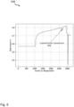
- Fig.8 shows the simulated voltage curves of a battery module with a faulty battery cell in one embodiment and the calculated reference signal 801.
- the voltage curve of the reference signal 801 is formed by calculating the median of all cell voltages of a module.
- the median is more suitable as a reference than the arithmetic mean, since outliers have a much smaller influence on the median.
- X x 1.1 x 1.2 ⁇ x 1 , j ⁇ x 1 , n x 2.1 x 2.2 ⁇ x 2 , j ⁇ x 2 , n ⁇ ⁇ ⁇ ⁇ ⁇ x i , 1 x i , 2 ⁇ x i , j ⁇ x i , n ⁇ ⁇ ⁇ ⁇ ⁇ x m , 1 x m , 2 ⁇ x m , j ⁇ x m , n with i ⁇ N , 1 ⁇ i ⁇ m and j ⁇ N , 1 ⁇ j ⁇ n
- the generated reference signal is used to detect the cell that differs most from the other cells in a module in terms of voltage profile.
- the reference signal is generated anew for each module. Since several cells in a module may have different anomalies, a comparison is made between the cell voltage and the reference voltage for each segment. The steps for feature extraction in the respective segments are explained below.
- the offset voltage is also compensated in the third segment, since only the relative voltage jump allows conclusions to be drawn about the internal resistance of a cell. At present, voltage jumps that are too high, which are an indication of high internal resistance, are considered just as much anomalies as voltage jumps that are too low, since the voltage differences are also considered in terms of their magnitude.
- Entry c k , l with l ⁇ N and 1 ⁇ l ⁇ 3 of the vector v ⁇ feat , k represents the principal component of the l -th segment and the k -th module transformed by principal component analysis (PCA).
- PCA principal component analysis
- the feature vectors can then be displayed as points in three-dimensional space.
- the data points are colored according to their groups.
- Fig.9 are the individual feature vectors for the cases from Table 200 in Fig.2 shown.
- Fig.9 The result of the feature extraction can be seen using a sample data set. It can be seen that the different groups are clearly separated from each other. This allows us to conclude that the feature extraction was successful.
- classification algorithms such as logistic regression, support vector machine, random forest, multilayer perceptron can be tested.
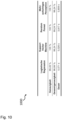
- Fig.10 shows a table 1000 of the results of the different classification algorithms when trained with k-means in one embodiment. As can be seen from the Fig.10 is evident, the Support Vector Machine delivers the best result, with the Support Vector Machine correctly classifying the data in only 3% of the time required by the multilayer perceptron.
- a one-class support vector machine is used after the classifier to enable a more restrictive consideration of anomalies and normal cases. This should define strict limits for normal cases in the feature space based on normal cases contained in the training data.
- the boundary surface 1101 generated by the one-class support vector machine can be seen. All data points that lie outside this boundary are declared anomalies regardless of the result of the classifier. In order to be able to assign an anomaly type, the label with the second highest probability is assigned.
- Fig. 12 shows a flowchart for a method 1200 according to an embodiment.
- the method 1200 for battery management comprises, as a first method step, obtaining 1201 a first voltage curve across a first battery cell of a battery module and a second voltage curve across a second battery cell of the battery module, wherein the first voltage curve has a first voltage curve section and a second voltage curve section, and wherein the second voltage curve has a third voltage curve section and a fourth voltage curve section.
- the method 1200 comprises, as a second method step, determining 1203 a reference voltage curve on the basis of an average voltage value from the first voltage curve and from the second voltage curve, wherein the reference voltage curve has a first reference voltage curve section and a second reference voltage curve section.
- the method 1200 comprises, as a third method step, comparing 1205 the first voltage curve with the reference voltage curve to obtain a first metric which comprises a first voltage deviation between the first voltage curve section and the first reference voltage curve section and a second Voltage deviation between the second voltage waveform section and the second reference voltage waveform section.
- the method 1200 comprises, as a fourth method step, comparing 1207 the second voltage waveform with the reference voltage waveform to obtain a second metric indicating a third voltage deviation between the third voltage waveform section and the first reference voltage waveform section and a fourth voltage deviation between the fourth voltage waveform section and the second reference voltage waveform section;
- the method 1200 comprises, as a fifth method step, assigning 1209 a first electrical characteristic to the first voltage profile section and a second electrical characteristic to the second voltage profile section if the first metric is greater than the second metric in order to classify the battery module by the first electrical characteristic and the second electrical characteristic, or, as a sixth method step, assigning 1211 a third electrical characteristic to the third voltage profile section and a fourth electrical characteristic to the second voltage profile section if the first metric is smaller than the second metric in order to classify the battery module by the third electrical characteristic and the fourth electrical characteristic.
Landscapes
- Physics & Mathematics (AREA)
- General Physics & Mathematics (AREA)
- Secondary Cells (AREA)
Applications Claiming Priority (2)
| Application Number | Priority Date | Filing Date | Title |
|---|---|---|---|
| DE102020121098.1A DE102020121098A1 (de) | 2020-08-11 | 2020-08-11 | Batteriemanagementsystem zum Klassifizieren eines Batteriemoduls |
| PCT/EP2021/069620 WO2022033794A1 (de) | 2020-08-11 | 2021-07-14 | Batteriemanagementsystem zum klassifizieren eines batteriemoduls |
Publications (2)
| Publication Number | Publication Date |
|---|---|
| EP4196805A1 EP4196805A1 (de) | 2023-06-21 |
| EP4196805B1 true EP4196805B1 (de) | 2024-09-04 |
Family
ID=77207153
Family Applications (1)
| Application Number | Title | Priority Date | Filing Date |
|---|---|---|---|
| EP21749774.2A Active EP4196805B1 (de) | 2020-08-11 | 2021-07-14 | Batteriemanagementsystem zum klassifizieren eines batteriemoduls |
Country Status (8)
| Country | Link |
|---|---|
| US (1) | US20230194624A1 (pl) |
| EP (1) | EP4196805B1 (pl) |
| CN (1) | CN116075733A (pl) |
| DE (1) | DE102020121098A1 (pl) |
| ES (1) | ES2991734T3 (pl) |
| HU (1) | HUE068748T2 (pl) |
| PL (1) | PL4196805T3 (pl) |
| WO (1) | WO2022033794A1 (pl) |
Families Citing this family (6)
| Publication number | Priority date | Publication date | Assignee | Title |
|---|---|---|---|---|
| EP4123321B1 (de) * | 2021-07-23 | 2024-10-30 | Siemens Aktiengesellschaft | Verfahren, vorrichtung und computerprogrammprodukt zur restwertbestimmung von batteriespeichern |
| CN114720878B (zh) * | 2022-03-24 | 2022-10-11 | 长安大学 | 一种退役电池的状态检测方法 |
| CN115015768B (zh) * | 2022-08-10 | 2022-11-11 | 力高(山东)新能源技术股份有限公司 | 一种预测电池组异常电芯的方法 |
| CN117092514B (zh) * | 2023-07-05 | 2025-10-31 | 西北工业大学 | 一种基于随机森林算法的锂离子电池分组方法 |
| CN116699428B (zh) * | 2023-08-08 | 2023-10-10 | 深圳市杰成镍钴新能源科技有限公司 | 退役电池的缺陷检测方法及装置 |
| CN118501720B (zh) * | 2024-07-17 | 2024-09-20 | 山东高质新能源检测有限公司 | 一种基于大数据分析的锂电池异常检测系统 |
Family Cites Families (10)
| Publication number | Priority date | Publication date | Assignee | Title |
|---|---|---|---|---|
| CN1264471A (zh) * | 1997-06-19 | 2000-08-23 | 斯耐普昂仪器有限公司 | 电池试验和分类 |
| JP4973112B2 (ja) * | 2006-10-06 | 2012-07-11 | パナソニック株式会社 | 充電装置と蓄電池の状態検知装置とからなるシステム |
| US9366732B2 (en) * | 2009-09-04 | 2016-06-14 | Board Of Regents, The University Of Texas System | Estimation of state-of-health in batteries |
| EP3040732B1 (en) * | 2013-08-30 | 2020-12-09 | NGK Insulators, Ltd. | Device, method, and program for specifying abnormality-occurrence area of secondary battery system |
| DE102013017061A1 (de) | 2013-10-15 | 2014-07-24 | Daimler Ag | Bestimmung der Degradierung eines Akkumulators in einem Hybridfahrzeug |
| JP2015166710A (ja) * | 2014-03-04 | 2015-09-24 | ソニー株式会社 | 蓄電部材状態推定装置、電池パック、電動車両、蓄電装置および蓄電部材状態推定方法 |
| KR101684092B1 (ko) | 2015-04-08 | 2016-12-07 | 현대자동차주식회사 | 열화도 산출 장치 및 방법 |
| DE102016200289A1 (de) * | 2016-01-13 | 2017-07-13 | Robert Bosch Gmbh | Verfahren zur Diagnose eines elektrischen Energiespeichers und Diagnosevorrichtung für einen elektrischen Energiespeicher |
| JP6380417B2 (ja) * | 2016-01-21 | 2018-08-29 | 横河電機株式会社 | 二次電池容量測定システム及び二次電池容量測定方法 |
| DE102016215991A1 (de) * | 2016-08-25 | 2018-03-01 | Siemens Aktiengesellschaft | Verfahren zur Bestimmung des Alters eines elektrochemischen Energiespeichers |
-
2020
- 2020-08-11 DE DE102020121098.1A patent/DE102020121098A1/de active Pending
-
2021
- 2021-07-14 ES ES21749774T patent/ES2991734T3/es active Active
- 2021-07-14 PL PL21749774.2T patent/PL4196805T3/pl unknown
- 2021-07-14 HU HUE21749774A patent/HUE068748T2/hu unknown
- 2021-07-14 WO PCT/EP2021/069620 patent/WO2022033794A1/de not_active Ceased
- 2021-07-14 EP EP21749774.2A patent/EP4196805B1/de active Active
- 2021-07-14 CN CN202180056244.XA patent/CN116075733A/zh active Pending
-
2023
- 2023-02-13 US US18/108,887 patent/US20230194624A1/en active Pending
Also Published As
| Publication number | Publication date |
|---|---|
| CN116075733A (zh) | 2023-05-05 |
| DE102020121098A1 (de) | 2022-02-17 |
| ES2991734T3 (es) | 2024-12-04 |
| EP4196805A1 (de) | 2023-06-21 |
| HUE068748T2 (hu) | 2025-01-28 |
| WO2022033794A1 (de) | 2022-02-17 |
| PL4196805T3 (pl) | 2024-11-04 |
| US20230194624A1 (en) | 2023-06-22 |
Similar Documents
| Publication | Publication Date | Title |
|---|---|---|
| EP4196805B1 (de) | Batteriemanagementsystem zum klassifizieren eines batteriemoduls | |
| EP3921658B1 (de) | Verfahren und prüfvorrichtung | |
| DE102018216518A1 (de) | Verfahren und Vorrichtung zur Diagnose von Batteriezellen | |
| DE112019005914T5 (de) | Kategorisierung gewonnener daten basierend auf expliziten und impliziten mitteln | |
| DE102018109819A1 (de) | Verfahren zur Gewinnung von Information aus Röntgen-Computertomographiedaten zur Optimierung des Spritzgussprozesses von kurzfaserverstärkten Kunststoffteilen | |
| EP4165484B1 (de) | Überwachungsvorrichtung und verfahren zur anomaliedetektion | |
| EP3282399A1 (de) | Verfahren zur verbesserten erkennung von prozessanomalien einer technischen anlage sowie entsprechendes diagnosesystem | |
| DE102019206859A1 (de) | Produkttestverfahren, Produkttestvorrichtung und Produkttestsystem zum Test elektronischer Baugruppen | |
| DE102018216517A1 (de) | Verfahren und Vorrichtung zur Diagnose von Batteriezellen | |
| DE102020201183A1 (de) | Verfahren und Vorrichtung zur Simulation eines technischen Systems | |
| EP3460727A1 (de) | Verfahren zur untersuchung eines funktionsverhaltens eines technischen systems und auswerteeinheit | |
| EP3796117B1 (de) | Diagnoseverfahren und diagnosesystem für eine verfahrenstechnische anlage | |
| DE10111831A1 (de) | Verfahren zum automatischen Suchen und Sortieren von Fehlersignaturen von Wafern | |
| DE112018006847B4 (de) | Anzeigedatenerzeugungsvorrichtung, Anzeigedatenerzeugungsverfahren und Programm | |
| DE102022200285B3 (de) | Verfahren und Vorrichtung zum Bereitstellen eines datenbasierten Systemmodells und zum Überprüfen eines Trainingszustands des Systemmodells | |
| DE102023104218A1 (de) | Erkennung des Batteriezustands basierend auf dem natürlichen Konditionierungsverhalten | |
| DE102018003222A1 (de) | Verfahren zum Prüfen einer eine Mehrzahl drehbarer Komponenten aufweisenden Drehkomponentenanordnung | |
| DE112020007637T5 (de) | Lerneinrichtung, fehler-erfassungseinrichtung und fehler-erfassungsverfahren | |
| EP3926636A2 (de) | Verfahren zum erkennen einer amplifikationsphase in einer amplifikation | |
| DE10133689A1 (de) | Testverfahren und Testvorrichtung für elektronische Speicher | |
| DE102024204830A1 (de) | Computerimplementiertes Verfahren zum Bilden von Klassen beim Trainieren eines Algorithmus des maschinellen Lernens für die Klassifikation von Prozessdaten eines industriellen Prozesses | |
| DE102022116756A1 (de) | Verfahren zur Qualitätskontrolle, Verfahren zum Herstellen eines Bauteils | |
| DE102025104599A1 (de) | System zum vorhersagen der gesundheit von batteriezellen | |
| DE102023205380A1 (de) | Verfahren zum Untersuchen einer elektrochemischen Zelle durch eine elektrochemische Impedanzspektroskopie | |
| DE102024003306A1 (de) | Qualitätsüberwachung von Batteriezellen mittels Raman-Spektroskopie |
Legal Events
| Date | Code | Title | Description |
|---|---|---|---|
| STAA | Information on the status of an ep patent application or granted ep patent |
Free format text: STATUS: UNKNOWN |
|
| STAA | Information on the status of an ep patent application or granted ep patent |
Free format text: STATUS: THE INTERNATIONAL PUBLICATION HAS BEEN MADE |
|
| PUAI | Public reference made under article 153(3) epc to a published international application that has entered the european phase |
Free format text: ORIGINAL CODE: 0009012 |
|
| STAA | Information on the status of an ep patent application or granted ep patent |
Free format text: STATUS: REQUEST FOR EXAMINATION WAS MADE |
|
| 17P | Request for examination filed |
Effective date: 20230207 |
|
| AK | Designated contracting states |
Kind code of ref document: A1 Designated state(s): AL AT BE BG CH CY CZ DE DK EE ES FI FR GB GR HR HU IE IS IT LI LT LU LV MC MK MT NL NO PL PT RO RS SE SI SK SM TR |
|
| DAV | Request for validation of the european patent (deleted) | ||
| DAX | Request for extension of the european patent (deleted) | ||
| GRAP | Despatch of communication of intention to grant a patent |
Free format text: ORIGINAL CODE: EPIDOSNIGR1 |
|
| STAA | Information on the status of an ep patent application or granted ep patent |
Free format text: STATUS: GRANT OF PATENT IS INTENDED |
|
| INTG | Intention to grant announced |
Effective date: 20240412 |
|
| GRAS | Grant fee paid |
Free format text: ORIGINAL CODE: EPIDOSNIGR3 |
|
| GRAA | (expected) grant |
Free format text: ORIGINAL CODE: 0009210 |
|
| STAA | Information on the status of an ep patent application or granted ep patent |
Free format text: STATUS: THE PATENT HAS BEEN GRANTED |
|
| AK | Designated contracting states |
Kind code of ref document: B1 Designated state(s): AL AT BE BG CH CY CZ DE DK EE ES FI FR GB GR HR HU IE IS IT LI LT LU LV MC MK MT NL NO PL PT RO RS SE SI SK SM TR |
|
| REG | Reference to a national code |
Ref country code: GB Ref legal event code: FG4D Free format text: NOT ENGLISH |
|
| REG | Reference to a national code |
Ref country code: CH Ref legal event code: EP |
|
| REG | Reference to a national code |
Ref country code: IE Ref legal event code: FG4D Free format text: LANGUAGE OF EP DOCUMENT: GERMAN |
|
| REG | Reference to a national code |
Ref country code: DE Ref legal event code: R096 Ref document number: 502021005067 Country of ref document: DE |
|
| REG | Reference to a national code |
Ref country code: SE Ref legal event code: TRGR |
|
| REG | Reference to a national code |
Ref country code: ES Ref legal event code: FG2A Ref document number: 2991734 Country of ref document: ES Kind code of ref document: T3 Effective date: 20241204 |
|
| REG | Reference to a national code |
Ref country code: LT Ref legal event code: MG9D |
|
| REG | Reference to a national code |
Ref country code: NL Ref legal event code: MP Effective date: 20240904 |
|
| PG25 | Lapsed in a contracting state [announced via postgrant information from national office to epo] |
Ref country code: NO Free format text: LAPSE BECAUSE OF FAILURE TO SUBMIT A TRANSLATION OF THE DESCRIPTION OR TO PAY THE FEE WITHIN THE PRESCRIBED TIME-LIMIT Effective date: 20241204 |
|
| PG25 | Lapsed in a contracting state [announced via postgrant information from national office to epo] |
Ref country code: GR Free format text: LAPSE BECAUSE OF FAILURE TO SUBMIT A TRANSLATION OF THE DESCRIPTION OR TO PAY THE FEE WITHIN THE PRESCRIBED TIME-LIMIT Effective date: 20241205 Ref country code: FI Free format text: LAPSE BECAUSE OF FAILURE TO SUBMIT A TRANSLATION OF THE DESCRIPTION OR TO PAY THE FEE WITHIN THE PRESCRIBED TIME-LIMIT Effective date: 20240904 |
|
| PG25 | Lapsed in a contracting state [announced via postgrant information from national office to epo] |
Ref country code: BG Free format text: LAPSE BECAUSE OF FAILURE TO SUBMIT A TRANSLATION OF THE DESCRIPTION OR TO PAY THE FEE WITHIN THE PRESCRIBED TIME-LIMIT Effective date: 20240904 |
|
| PG25 | Lapsed in a contracting state [announced via postgrant information from national office to epo] |
Ref country code: LV Free format text: LAPSE BECAUSE OF FAILURE TO SUBMIT A TRANSLATION OF THE DESCRIPTION OR TO PAY THE FEE WITHIN THE PRESCRIBED TIME-LIMIT Effective date: 20240904 |
|
| PG25 | Lapsed in a contracting state [announced via postgrant information from national office to epo] |
Ref country code: HR Free format text: LAPSE BECAUSE OF FAILURE TO SUBMIT A TRANSLATION OF THE DESCRIPTION OR TO PAY THE FEE WITHIN THE PRESCRIBED TIME-LIMIT Effective date: 20240904 |
|
| PG25 | Lapsed in a contracting state [announced via postgrant information from national office to epo] |
Ref country code: RS Free format text: LAPSE BECAUSE OF FAILURE TO SUBMIT A TRANSLATION OF THE DESCRIPTION OR TO PAY THE FEE WITHIN THE PRESCRIBED TIME-LIMIT Effective date: 20241204 |
|
| REG | Reference to a national code |
Ref country code: HU Ref legal event code: AG4A Ref document number: E068748 Country of ref document: HU |
|
| PG25 | Lapsed in a contracting state [announced via postgrant information from national office to epo] |
Ref country code: RS Free format text: LAPSE BECAUSE OF FAILURE TO SUBMIT A TRANSLATION OF THE DESCRIPTION OR TO PAY THE FEE WITHIN THE PRESCRIBED TIME-LIMIT Effective date: 20241204 Ref country code: NO Free format text: LAPSE BECAUSE OF FAILURE TO SUBMIT A TRANSLATION OF THE DESCRIPTION OR TO PAY THE FEE WITHIN THE PRESCRIBED TIME-LIMIT Effective date: 20241204 Ref country code: LV Free format text: LAPSE BECAUSE OF FAILURE TO SUBMIT A TRANSLATION OF THE DESCRIPTION OR TO PAY THE FEE WITHIN THE PRESCRIBED TIME-LIMIT Effective date: 20240904 Ref country code: HR Free format text: LAPSE BECAUSE OF FAILURE TO SUBMIT A TRANSLATION OF THE DESCRIPTION OR TO PAY THE FEE WITHIN THE PRESCRIBED TIME-LIMIT Effective date: 20240904 Ref country code: GR Free format text: LAPSE BECAUSE OF FAILURE TO SUBMIT A TRANSLATION OF THE DESCRIPTION OR TO PAY THE FEE WITHIN THE PRESCRIBED TIME-LIMIT Effective date: 20241205 Ref country code: FI Free format text: LAPSE BECAUSE OF FAILURE TO SUBMIT A TRANSLATION OF THE DESCRIPTION OR TO PAY THE FEE WITHIN THE PRESCRIBED TIME-LIMIT Effective date: 20240904 Ref country code: BG Free format text: LAPSE BECAUSE OF FAILURE TO SUBMIT A TRANSLATION OF THE DESCRIPTION OR TO PAY THE FEE WITHIN THE PRESCRIBED TIME-LIMIT Effective date: 20240904 |
|
| PG25 | Lapsed in a contracting state [announced via postgrant information from national office to epo] |
Ref country code: NL Free format text: LAPSE BECAUSE OF FAILURE TO SUBMIT A TRANSLATION OF THE DESCRIPTION OR TO PAY THE FEE WITHIN THE PRESCRIBED TIME-LIMIT Effective date: 20240904 |
|
| PG25 | Lapsed in a contracting state [announced via postgrant information from national office to epo] |
Ref country code: IS Free format text: LAPSE BECAUSE OF FAILURE TO SUBMIT A TRANSLATION OF THE DESCRIPTION OR TO PAY THE FEE WITHIN THE PRESCRIBED TIME-LIMIT Effective date: 20250104 Ref country code: PT Free format text: LAPSE BECAUSE OF FAILURE TO SUBMIT A TRANSLATION OF THE DESCRIPTION OR TO PAY THE FEE WITHIN THE PRESCRIBED TIME-LIMIT Effective date: 20250106 |
|
| PG25 | Lapsed in a contracting state [announced via postgrant information from national office to epo] |
Ref country code: SM Free format text: LAPSE BECAUSE OF FAILURE TO SUBMIT A TRANSLATION OF THE DESCRIPTION OR TO PAY THE FEE WITHIN THE PRESCRIBED TIME-LIMIT Effective date: 20240904 Ref country code: RO Free format text: LAPSE BECAUSE OF FAILURE TO SUBMIT A TRANSLATION OF THE DESCRIPTION OR TO PAY THE FEE WITHIN THE PRESCRIBED TIME-LIMIT Effective date: 20240904 |
|
| PG25 | Lapsed in a contracting state [announced via postgrant information from national office to epo] |
Ref country code: EE Free format text: LAPSE BECAUSE OF FAILURE TO SUBMIT A TRANSLATION OF THE DESCRIPTION OR TO PAY THE FEE WITHIN THE PRESCRIBED TIME-LIMIT Effective date: 20240904 |
|
| PG25 | Lapsed in a contracting state [announced via postgrant information from national office to epo] |
Ref country code: CZ Free format text: LAPSE BECAUSE OF FAILURE TO SUBMIT A TRANSLATION OF THE DESCRIPTION OR TO PAY THE FEE WITHIN THE PRESCRIBED TIME-LIMIT Effective date: 20240904 |
|
| PG25 | Lapsed in a contracting state [announced via postgrant information from national office to epo] |
Ref country code: IT Free format text: LAPSE BECAUSE OF FAILURE TO SUBMIT A TRANSLATION OF THE DESCRIPTION OR TO PAY THE FEE WITHIN THE PRESCRIBED TIME-LIMIT Effective date: 20240904 Ref country code: SK Free format text: LAPSE BECAUSE OF FAILURE TO SUBMIT A TRANSLATION OF THE DESCRIPTION OR TO PAY THE FEE WITHIN THE PRESCRIBED TIME-LIMIT Effective date: 20240904 |
|
| REG | Reference to a national code |
Ref country code: DE Ref legal event code: R097 Ref document number: 502021005067 Country of ref document: DE |
|
| PGFP | Annual fee paid to national office [announced via postgrant information from national office to epo] |
Ref country code: PL Payment date: 20250612 Year of fee payment: 5 |
|
| PG25 | Lapsed in a contracting state [announced via postgrant information from national office to epo] |
Ref country code: DK Free format text: LAPSE BECAUSE OF FAILURE TO SUBMIT A TRANSLATION OF THE DESCRIPTION OR TO PAY THE FEE WITHIN THE PRESCRIBED TIME-LIMIT Effective date: 20240904 |
|
| PGFP | Annual fee paid to national office [announced via postgrant information from national office to epo] |
Ref country code: GB Payment date: 20250529 Year of fee payment: 5 |
|
| PLBE | No opposition filed within time limit |
Free format text: ORIGINAL CODE: 0009261 |
|
| STAA | Information on the status of an ep patent application or granted ep patent |
Free format text: STATUS: NO OPPOSITION FILED WITHIN TIME LIMIT |
|
| PGFP | Annual fee paid to national office [announced via postgrant information from national office to epo] |
Ref country code: FR Payment date: 20250610 Year of fee payment: 5 |
|
| PGFP | Annual fee paid to national office [announced via postgrant information from national office to epo] |
Ref country code: SE Payment date: 20250610 Year of fee payment: 5 |
|
| PGFP | Annual fee paid to national office [announced via postgrant information from national office to epo] |
Ref country code: HU Payment date: 20250630 Year of fee payment: 5 |
|
| 26N | No opposition filed |
Effective date: 20250605 |
|
| PGFP | Annual fee paid to national office [announced via postgrant information from national office to epo] |
Ref country code: ES Payment date: 20250804 Year of fee payment: 5 |
|
| PGFP | Annual fee paid to national office [announced via postgrant information from national office to epo] |
Ref country code: DE Payment date: 20250731 Year of fee payment: 5 |
|
| PGFP | Annual fee paid to national office [announced via postgrant information from national office to epo] |
Ref country code: AT Payment date: 20251020 Year of fee payment: 5 |