EP4196331B1 - Electric component carrier - Google Patents
Electric component carrier Download PDFInfo
- Publication number
- EP4196331B1 EP4196331B1 EP21762018.6A EP21762018A EP4196331B1 EP 4196331 B1 EP4196331 B1 EP 4196331B1 EP 21762018 A EP21762018 A EP 21762018A EP 4196331 B1 EP4196331 B1 EP 4196331B1
- Authority
- EP
- European Patent Office
- Prior art keywords
- carrier element
- electronic component
- filling material
- gas bubbles
- contact surface
- Prior art date
- Legal status (The legal status is an assumption and is not a legal conclusion. Google has not performed a legal analysis and makes no representation as to the accuracy of the status listed.)
- Active
Links
Images
Classifications
-
- B—PERFORMING OPERATIONS; TRANSPORTING
- B29—WORKING OF PLASTICS; WORKING OF SUBSTANCES IN A PLASTIC STATE IN GENERAL
- B29C—SHAPING OR JOINING OF PLASTICS; SHAPING OF MATERIAL IN A PLASTIC STATE, NOT OTHERWISE PROVIDED FOR; AFTER-TREATMENT OF THE SHAPED PRODUCTS, e.g. REPAIRING
- B29C45/00—Injection moulding, i.e. forcing the required volume of moulding material through a nozzle into a closed mould; Apparatus therefor
- B29C45/0005—Injection moulding, i.e. forcing the required volume of moulding material through a nozzle into a closed mould; Apparatus therefor using fibre reinforcements
-
- B—PERFORMING OPERATIONS; TRANSPORTING
- B29—WORKING OF PLASTICS; WORKING OF SUBSTANCES IN A PLASTIC STATE IN GENERAL
- B29C—SHAPING OR JOINING OF PLASTICS; SHAPING OF MATERIAL IN A PLASTIC STATE, NOT OTHERWISE PROVIDED FOR; AFTER-TREATMENT OF THE SHAPED PRODUCTS, e.g. REPAIRING
- B29C45/00—Injection moulding, i.e. forcing the required volume of moulding material through a nozzle into a closed mould; Apparatus therefor
- B29C45/17—Component parts, details or accessories; Auxiliary operations
- B29C45/1703—Introducing an auxiliary fluid into the mould
- B29C45/1704—Introducing an auxiliary fluid into the mould the fluid being introduced into the interior of the injected material which is still in a molten state, e.g. for producing hollow articles
-
- B—PERFORMING OPERATIONS; TRANSPORTING
- B29—WORKING OF PLASTICS; WORKING OF SUBSTANCES IN A PLASTIC STATE IN GENERAL
- B29L—INDEXING SCHEME ASSOCIATED WITH SUBCLASS B29C, RELATING TO PARTICULAR ARTICLES
- B29L2031/00—Other particular articles
- B29L2031/34—Electrical apparatus, e.g. sparking plugs or parts thereof
- B29L2031/3481—Housings or casings incorporating or embedding electric or electronic elements
Definitions
- the present invention relates to a device for enclosing an electronic component in a moisture-tight manner. A method for producing the device is also described.
- a device for moisture-tight housing of an electronic component and its conductor has a fiber-reinforced, injection-molded carrier element which has a cavity for receiving the electronic component and consists of a thermoplastic.
- the device also has the electronic component which is arranged in the cavity.
- the device also has a filling compound which adheres to the carrier element and the electronic component and is arranged between the electronic component and the carrier element.
- the device also has an electrical conductor which is coupled to the electronic component and the carrier element and is at least partially surrounded by the filling compound.
- the carrier element contains gas bubbles which are less than 10 mm away from the filling compound.
- a method for producing a device described above for enclosing a conductor of an electronic component in a moisture-tight manner comprises injection molding of a fiber-reinforced carrier element which has a cavity for receiving the electronic component and is made of a thermoplastic material.
- the electronic Component is arranged in the cavity and an electrical conductor is coupled to the electronic component and the carrier element.
- a filling compound is filled between the electronic component and the carrier element, whereby the filling compound adheres to the carrier element and the electronic component and the electrical conductor is at least partially surrounded by the filling compound.
- the carrier element contains gas bubbles which are less than 10 mm away from the filling compound.
- the electronic components can be, for example, microswitches, wire resistors, MEMs (Micro-Electro-Mechanical Systems) or integrated circuits (IC, with SMD or DIL connections).
- the term "electronic component” also includes electrical components such as fuses and the like.
- an electronic component is inserted into a corresponding cavity of the carrier element.
- several electronic components can be inserted into a corresponding cavity of the carrier element or the carrier element can have several cavities in each of which an electronic component can be inserted.
- the electronic component also has an electrical conductor, which can be used to transmit energy or signals, in particular to the environment.
- the electrical conductors are often rigidly attached electrical connections made of solid conductors.
- the term "electronic components” is used to summarize various electrical, electromechanical or electronic components that are embedded in the carrier element, which is designed as an injection-molded housing. In particular, the electronic components are designed to make contact with solid conductor-based connections, which can be electrically conductively coupled to corresponding conductors in the carrier element.
- the carrier element is in particular a fiber-reinforced, injection-molded component that has sufficient strength and hardness.
- the carrier element has the cavity in which the electronic component (or, in an exemplary embodiment, several electronic components) can be embedded.
- the carrier element and its cavity can be designed such that at least two sides of an electronic component can be covered.
- a cavity can be formed by means of a V-shaped or L-shaped carrier element.
- the cavity can also be designed such that at least one side of the component remains free and is not covered by an area of the carrier element.
- the cavity can have an opening into which the electronic component can be inserted, wherein this opening can then be closed by a cover element.
- the carrier element is particularly fiber-reinforced to ensure high strength.
- Fiber-reinforcement materials can be used which, embedded in a polymer matrix, create a fiber composite.
- the filling compound (potting compound) at least partially envelops the electronic component and forms a fastening of the electronic component in the cavity of the carrier element.
- Castable plastics based on PUR (polyurethane) or epoxy can be used as the potting compound.
- the filling compound adheres in particular to the electronic component and is arranged between the electronic component and the carrier element in order to fasten the electronic component accordingly.
- Injection-molded fiber-reinforced carrier elements often produce smooth surfaces that make it difficult for the filling compound to adhere.
- gas bubbles are present in the carrier element in an area that is less than 10 mm away from the filling compound.
- an area is created which extends from a contact surface (surface) of the carrier element with the filling compound at least 10 mm (millimeters) or more into the interior of the carrier element. The distance of 10 mm can be measured, for example, along a perpendicular to the contact surface from the contact surface into the interior of the carrier element.
- the present invention thus allows moisture-resistant embedding of electronic components in cavities formed by a fiber-reinforced component carrier, wherein the cavities are filled with a filling compound.
- a self-organizing surface change of the injection molded part (carrier element) is achieved, particularly when gas, in particular nitrogen, is added in the injection molding process, which leads to improved adhesion.
- the gas bubble content is between 1 vol.% (volume percent) and 30 vol.%, in particular between 2 vol.% and 10 vol.%.
- the strength of the carrier element is thus only insignificantly reduced by the introduction of gas bubbles, so that sufficient stability is guaranteed despite the presence of gas bubbles in the carrier element.
- the pore volume also reduces the use of material. However, as the pore content increases, this usually comes at the expense of the component strength. A pore volume of 1-30 vol.% is therefore aimed for (in particular, good results have been achieved in the range 2 vol.% -10 vol.%) in order to optimize the mechanical properties.
- the gas bubbles have a pore size of 10 to 50 ⁇ m (micrometers), in particular 20 to 40 ⁇ m. It has been found that, in particular, with a The corresponding size of the gas bubbles results in self-organization of the fiber alignment and microstructuring of the contact surface.
- the pore size is determined by the largest distance between two opposite edge points in a gas bubble.
- the carrier element has a proportion of polypropylene PP (eg Thermofil ® HPF610X99) or in particular consists predominantly (eg exclusively) of polypropylene.
- the carrier element can have proportions of thermoplastic polyurethane TPU, acrylonitrile-butadiene-styrene copolymers ABS, polycarbonate PC and/or polyoxymethylene POM, polyamide PA and/or polystyrene PS.
- the electrical conductor penetrates the surface of the carrier element such that this penetration lies in a contact area between the carrier element and the filling compound.
- the gas bubbles are formed closer than 10 mm, in particular closer than 4 mm, in particular closer than 2 mm, to the electrical conductor. Due to the rigidity of the conductor (in particular a solid conductor), the gas bubbles expanding in the cooling phase will increasingly expand away from the conductor. This creates a region of particularly pronounced stubble in the area. As a result, the adhesion of the filling compound is particularly high in the area and particularly good long-term moisture protection properties are achieved. Particularly good results were achieved when gas bubbles are closer than 20 mm, in particular closer than 8 mm, particularly preferably closer than 3 mm to the conductor.
- the gas bubbles contain inert gases, in particular nitrogen.
- inert gases in particular nitrogen.
- Inert gases hardly react with the fiber elements or with the material of the carrier element, so that good compatibility with the surrounding materials is ensured.
- the contact surface of the carrier element in the contact zone with the filling compound has exposed reinforcing fibers and/or microcrystalline cavities.
- this leads to improved adhesion of the filling compound.
- Glass fiber stubble and microcavities are utilized by the casting compound (filling compound) as mechanical clamping for improved adhesion. This improved adhesion of the casting compound thus achieved also allows good tightness with regard to moisture migration.
- the carrier element has at least two regions with different concentrations of a gas bubble density.
- a first region which represents the region from the contact surface into the interior of the carrier element, can have a higher density of gas bubbles than a second region, which borders the first region and is spaced from the contact surface.
- the first region which borders the contact surface and has the higher proportion of gas bubbles, can preferably form the microcavities and the exposed fiber components.
- the deeper second region with a lower density of gas bubbles can, for example, lead to a higher density of the carrier element and thus to, for example, greater durability and hardness of the carrier element. Properties of the carrier element can thus be specifically adjusted.
- the carrier element has different coefficients of static friction in a contact surface with the filling compound in different directions along the contact surface.
- the property of the alignment of fibers in the direction of flow is utilized. This means that a desired flow direction of the polymer fiber mixture can be achieved in the injection molded part by suitable mold construction. The subsequent expansion of the gas creates fiber parts with a preferred orientation on the surface. This in turn leads to increased retention of the filler in this direction according to the principle of higher resistance, i.e. figuratively speaking, like "stroking against the beard.” If, for example, the fiber ends on the contact surface are oriented in a fiber direction, the coefficient of static friction against this fiber direction is higher than in the fiber direction. Accordingly, the coefficients of static friction on the contact surface orthogonal to the fiber direction are smaller than against the fiber direction.
- the carrier element has a contact surface with the filling compound, wherein the contact surface is structured and in particular has a wave-shaped surface and/or a grooved surface. This increases in particular the contact surface of the carrier element with the filling compound and, for example, the roughness. This leads to a stronger connection between the carrier element and the filling compound.
- the cavity of the carrier element has an opening through which the electronic component protrudes into the environment with a protruding area.
- the protruding area and the carrier element there is at least one area with filling compound in such a way that an interior region of the device is sealed from the environment of the device in a liquid-tight manner.
- sealing by means of the filling material is provided, so that a seal, in particular against liquids, is provided between the further interior volume of the device and the environment. Sealing by means of direct contact between the carrier element and the electronic component is often difficult to achieve. Filling this distance region with the filling compound increases the sealing effect. This enables watertightness in accordance with IP 67 in particular.
- the carrier element has at least one positioning element against which the electronic component rests and can be positioned.
- the positioning element is, for example, a web or an edge or step to form a seat or support for the electronic component.
- the positioning element is, for example, integrally formed with the carrier element and can be manufactured in a common injection molding process.
- the positioning element is a guide pin, a guide rail or a guide track to which a corresponding coupling element (i.e., for example, a housing part) of the electronic component can be coupled.
- the carrier element comprises a polymer with a melt flow index (Melt Volume-flow Rate, MFR) of less than 5 g/10min, in particular less than 1 g/10min.
- MFR melt flow index
- the melt flow index is used to characterize the flow behavior (molding compound test) of a thermoplastic under certain pressure and temperature conditions.
- a gas in particular nitrogen, is injected during the injection molding process.
- the injection of gas into molten polymers during injection molding processes has the effect that the finely divided ("dissolving") of gas in the polymer melt leads to a significant reduction in viscosity.
- the flow properties of the melt are therefore improved and even small cross sections in the cavity are more easily flowed through or reached.
- a significant holding pressure i.e. a static pressure after injection into the injection mold, must be maintained until the polymer melt reaches even the furthest points of the injection mold.
- any shrinkage due to volume reduction during solidification must be compensated.
- the effect of this holding pressure decreases progressively with distance from the injection point, so that in order to achieve the production target, particularly with complex, thin-walled parts or component carriers and when using polymers with a low MFR (e.g. PP with MFR below 5 g/10min, especially below 1 g/10min) or highly filled blends (e.g.
- the carrier element has a fiber content in weight percent between 5% and 60%, in particular between 10% and 50%, and further in particular between 15% and 40%.
- the carrier element has reinforcing fibers consisting of mineral fibers, in particular silicates, glass, basalt, asbestos, wollastonite, carbon fibers, in particular carbon nanotubes, polymer fibers, in particular polyamide fibers, polyimide fibers, polyesters, polyolefins, polyesteramides, aramids, in particular Kevlar(r) ® and/or natural fibers, in particular cellulose, cotton, viscose, Lyocell ® , wood, hemp, silk.
- mineral fibers in particular silicates, glass, basalt, asbestos, wollastonite
- carbon fibers in particular carbon nanotubes
- polymer fibers in particular polyamide fibers, polyimide fibers, polyesters, polyolefins, polyesteramides, aramids, in particular Kevlar(r) ® and/or natural fibers, in particular cellulose, cotton, viscose, Lyocell ® , wood, hemp, silk.
- the reinforcing fibers comprise long fibers with a length of 1 mm (millimeters) to 20 mm, in particular from 5 mm to 15 mm.
- the filling compound comprises polyurethane or epoxy resin, for example Fermadur A & B.
- the electrical conductor is a solid conductor, wherein the solid conductor in particular has a cross-section of 0.1 mm 2 to 10 mm 2 .
- a solid conductor consists in particular of a (monolithic) solid wire or solid sheet.
- a solid conductor differs from thicker strands (which are each formed from several individual conductors), in particular with a cross-section of more than 16 mm 2 . Solid conductors form a high level of stability and good conductivity.
- the electrical conductor for external connection runs from the electronic component through the carrier element, wherein the electrical conductor is connected to the electronic Component is electronically coupled by means of soldering, welding, plugging, in particular an insulation displacement connection and/or clamping.
- the electronic component is a microswitch, an actuator, a resistor or a sensor, in particular a temperature sensor or a distance switch.
- the carrier element weighs less than 1 kg.
- the injection molding step comprises mixing a material of the carrier element with an inert gas, in particular nitrogen, to form the gas bubbles and introducing the material with the gas bubbles into an injection mold.
- an inert gas in particular nitrogen
- the manufacturing device has, for example, a funnel which feeds the raw material of the carrier element (for example granulate) to an extruder.
- the raw material can be heated and mixed so that a homogeneous viscous mass is formed.
- the viscous mass is conveyed by the extruder to a nozzle, in particular a needle-type nozzle, through which nozzle the viscous material can be injected into an injection mold at a predetermined temperature, pressure and volume flow.
- a gas injector is also coupled, which introduces a gas, for example inert gas, in particular nitrogen, into the viscous material to form the gas bubbles.
- the viscous mass is mixed with the injected gas so that a homogeneous gas/viscous mass mixture is formed.
- the gas bubbles are homogeneous in this mixture.
- the homogeneous gas/viscous mass mixture is injected into an injection mold through the nozzle. Due to the variation of the injection pressure, the temperature, and the mass flow with which the homogeneous gas/viscous mass mixture is injected, different areas with different densities of gas bubbles and in particular different sizes of gas bubbles can be generated in the carrier element.
- a contact surface of the carrier element with the filling compound has a greater roughness than a corresponding surface of the injection mold, wherein in particular the surface has a microstructure which is at least partially filled with the filling compound, particularly preferably that the filling compound can adhere to fiber stubble.
- the greater roughness of the contact surface of the carrier element is formed in particular by the microstructuring by the gas bubbles and the exposed fibers on the contact surface. This means that even with a smooth surface of the injection mold, which is advantageous to prevent adhesion of the assigned material, a rougher contact surface of the carrier element is created to provide improved adhesion with the filling compound.
- an inert gas in particular nitrogen
- a gas pressure between 30 bar and 230 bar, in particular between 80 bar and 160 bar
- the gas injector described above is connected in the shear and mixing zone, in particular of the extruder. Due to the variation in the pressure and, for example, the temperature at which the gas is injected into the viscous mass in the extruder is flowed in, the size of the gas bubbles as well as the number or density of the gas bubbles in the viscous material can be adjusted.
- the step of introducing the material of the carrier element into the injection mold involves a maximum shot weight of 1 kg.
- shot weight is understood to mean the maximum shot quantity (in grams) of the plastic melt including all secondary materials (e.g. fibers) within one shot of an injection molding machine that completely fills an injection mold.
- the inert gas in the mixing step is present, in particular at least temporarily, in a supercritical state.
- the gas In the supercritical state the gas is present in both gaseous and liquid form. This leads to an improved distribution of the gas within the viscous mass of the carrier element. After leaving the supercritical state the gas is completely gaseous again, so that the gas bubbles then form in the viscous mass of the carrier element.
- fiber portions and fiber ends can penetrate to the surface, i.e. to the mold surface (contact surface), and generate a rough yet flat surface of the carrier element.
- the solution according to the invention for anchoring the casting compound (between the carrier element and the filling compound) using glass fibre plugs leads to a long-term good electrical connection for the electrical or electronic components built into the injection moulded part (carrier element).
- oxidation-related tearing of Cold welding can be avoided in pressure-based connection mechanisms.
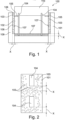
- Fig.1 shows a schematic representation of a device 100 in which an electrical conductor 104 is arranged between an electronic component 110 and a carrier element 101.
- the device 100 is designed to enclose the conductor 104 and at least partially the electronic component 110 in a moisture-tight manner.
- the device 100 has a fiber-reinforced, injection-molded carrier element 101 which has a cavity for receiving the electronic component 110 and consists of a thermoplastic material.
- the device 100 also has the electronic component 110 which is arranged in the cavity.
- a filling compound 102 adheres to the carrier element 101 and the electronic component 110 and is arranged between the electronic component 110 and the carrier element 101.
- the device 100 has an electrical conductor 104 which is coupled to the electronic component 110 and the carrier element 101 and is at least partially surrounded by the filling compound 102.
- the carrier element 101 is in particular a fiber-reinforced, injection-molded component which has sufficient strength and hardness.
- the carrier element 101 has the cavity in which the electronic component 110 is embedded.
- the carrier element 101 and its cavity can be designed such that at least two sides of an electronic component 110 can be covered.
- a cavity can be formed by means of a V-shaped or L-shaped carrier element 101.
- the cavity can also be designed such that at least one side of the component 110 remains free and is not covered by an area of the carrier element 101.
- the carrier element 101 is in particular fiber-reinforced to ensure high strength.
- Fiber-reinforcing materials can be used which, embedded in a polymer matrix, produce a fiber composite.
- the filling compound 102 (potting compound) at least partially envelops the electronic component 110 and forms a fastening of the electronic component 110 in the cavity of the carrier element 101.
- the filling compound 102 adheres in particular to the electronic component 110 and is arranged between the electronic component 110 and the carrier element 101 in order to fasten the electronic component 110 accordingly.
- gas bubbles 103 are present in the carrier element 101.
- the gas bubbles 104 are less than 10 mm away from the filling compound.
- an area is created which extends from a contact surface (surface) 107 of the carrier element with the filling compound 102 at least 10 mm (millimeters) or more into the interior of the carrier element 101.
- the 10 mm can be measured, for example, as a distance x along a perpendicular to the contact surface 107 from the contact surface 107 into the interior of the carrier element 101.
- gas bubbles 103 or cavities Due to the presence of gas bubbles 103 or cavities, corresponding depressions are formed on the contact surface 107 on the surface areas with open gas bubbles 103.
- the introduction of gas bubbles 103 impairs the orientation and formation of the fibers 106, so that after the hardening of the carrier element 101, fiber elements 106 or fiber ends are present on the contact surface 107.
- the proportion of gas bubbles, particularly in a first region 108 of the carrier element, can be set between 1 vol.% (volume percent) and 30 vol.%.
- the strength of the carrier element 101 is thus only insignificantly reduced by the introduction of gas bubbles 103, so that despite the presence of gas bubbles 103 in the carrier element 101, sufficient stability is ensured.
- the contact surface 107 of the carrier element 101 in the contact zone with the filling compound 102 has exposed reinforcing fibers 106 and/or microcrystalline cavities. As described above, this leads to improved adhesion of the filling compound 102. (Glass) fiber stubble and microcavities (gas bubbles 103) are utilized by the casting compound (filling compound 102) as mechanical clamping for improved adhesion.
- the carrier element 101 has, for example, at least two regions 108, 109 with different concentrations of a gas bubble density.
- a first region 108 which represents, for example, the region from the contact surface 107 into the interior of the carrier element, can have a higher density of gas bubbles 103 than a second region 109, which, for example, borders on the first region 108 and is spaced from the contact surface 107.
- the first region 108 which borders on the contact surface 107 and has the higher proportion of gas bubbles, can preferably form the microcavities and the exposed fiber components.
- the deeper second region 109 with a lower density of gas bubbles 103 can, for example, lead to a higher density of the carrier element 101 and thus to, for example, greater durability and hardness of the carrier element 101. Properties of the carrier element 101 can thus be specifically adjusted.
- the contact surface 107 can also be structured more coarsely and in particular have a wave-shaped surface and/or a grooved surface. This increases in particular the contact surface 107 of the carrier element 101 to the filling compound 102 and, for example, the roughness. This leads to a stronger connection between the carrier element 101 and the filling compound 102.
- the cavity of the carrier element 101 can have an opening through which the electronic component 110 protrudes into the environment with a protruding area. Between the protruding area and the carrier element 110 there is at least one area with filling compound 102 such that an inner area of the device 100 is sealed in a liquid-tight manner from the environment of the device.
- the sealing by means of the filling material 102 so that a seal, in particular against liquids, is provided between the internal volume of the device 100 and the environment.
- the carrier element 101 further comprises at least one positioning element 105 against which the electronic component 110 rests and can be positioned.
- the positioning element 105 is, for example, a web or an edge or step in order to form a seat or a support for the electronic component 110.
- the positioning element 105 is, for example, formed integrally with the carrier element 101 and can be manufactured in a common injection molding process.
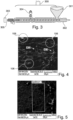
- Fig. 2 shows a sectional view of electrical conductors 104 which penetrate a carrier element 101.
- the electrical conductor is a solid conductor, wherein the solid conductor in particular has a cross-section of 0.1 mm 2 to 10 mm 2 .
- a solid conductor consists in particular of a (monolithic) solid wire or solid sheet.
- the electrical conductor 104 runs through the carrier element 101 for external connection from the electronic component 110, wherein the electrical conductor 104 is electronically coupled to the electronic component 110 by means of soldering, welding, plugging, in particular an insulation displacement connection and/or clamping.
- the electrical conductor 104 penetrates the surface of the carrier element 101 in such a way that this penetration lies in a contact surface 107 from the carrier element 101 to the filling compound 102.
- the gas bubbles 103 are formed, at least in some areas, closer than 10 mm to the electrical conductor 104 in the carrier element 101.
- Fig.3 shows a schematic representation of a manufacturing device 300 according to an exemplary embodiment of the present invention.
- the manufacturing device 300 has, for example, a funnel 301, which feeds the raw material of the carrier element 101 (for example granulate) to an extruder 302.
- the raw material can be heated and mixed so that a homogeneous viscous mass is formed.
- the viscous mass is conveyed by the extruder 302 to a nozzle 305, in particular a needle valve nozzle, through which nozzle 305 the viscous material can be injected into an injection mold 303 at a predetermined temperature, pressure and volume flow.
- a gas injector 304 is also coupled, which introduces a gas, for example inert gas, in particular nitrogen, into the viscous material to form the gas bubbles 103.
- a gas for example inert gas, in particular nitrogen
- the viscous mass is mixed with the injected gas so that a homogeneous gas/viscous mass mixture is formed.
- the gas bubbles 103 are present homogeneously in this mixture.
- the homogeneous gas/viscous mass mixture is injected into the injection mold 303 through the nozzle 305. Due to the variation of the injection pressure, the temperature, and the mass flow with which the homogeneous gas/viscous mass mixture is injected, different areas 108, 109 (see Fig.1 ) with different densities of gas bubbles 103 and in particular different sizes of gas bubbles 103 are generated in the carrier element 101.
- a contact surface of the carrier element with the filling compound has a greater roughness than a corresponding surface of the injection mold, wherein in particular the surface has a microstructure which is at least partially filled with the filling compound, particularly preferably that the filling compound can adhere to fiber stubble.
- the greater roughness of the contact surface of the carrier element 101 is formed in particular by the microstructuring by the gas bubbles 102 and the exposed fibers 106 on the contact surface. This means that even with a smooth surface of the injection mold 303, which is advantageous to prevent adhesion of the assigned material, a rougher contact surface 107 of the carrier element 101 is created in order to provide improved adhesion with the filling compound 102.
- gas injector 304 gas is fed into the extruder 302 and a material of the carrier element 101 is mixed with an inert gas, in particular nitrogen, to form the gas bubbles.
- a gas pressure of between 30 bar and 230 bar can be provided so that the inert gas is injected into a shear and mixing zone in the material of the carrier element 101. Due to the variation in the pressure and, for example, the temperature at which the gas is injected into the viscous mass in the extruder 302, a size of the gas bubbles and a number or density of the gas bubbles 103 in the viscous material can be adjusted.
- a significant holding pressure i.e. a static pressure after injection into the injection mold 303, must be maintained until the polymer melt reaches even the most remote points of the injection mold 303.
- the above-described regions 108, 109 with a higher or a lower gas bubble density in a carrier element 101 can be specifically set.
- Fig.4 shows a schematic representation of an SEM image of a contact surface 107 of a carrier element 101 with gas bubbles 103 according to an exemplary embodiment of the present invention.
- Fig.5 shows for comparison a schematic representation of a SEM image of a contact surface 107 of a carrier element 101 without gas bubbles 103.
- the glass fibers 106 protruding within the circles and the resulting microcavities 401 on the surface are marked with arrows.
- gas bubbles 103 are generated in the carrier element 101 in an injection molding process, glass fibers 106 emerge at the surface and/or microcavities 401 are formed, as shown in Fig.4 shown.
- These glass fiber plugs 106 and microcavities 401 can be used by the filling compound 102 as mechanical clamping for improved adhesion. This improved adhesion of the filling compound 102 thus achieved also allows for particularly good sealing with regard to moisture migration.
- a fiber-reinforced carrier element 101 without gas bubbles 103 As shown, in a fiber-reinforced carrier element 101 with gas bubbles 103 on the surface, pores (microcavities 401) that have come to rest during demolding and protrude into the matrix now open occur. A high number of open pores or microcavities 401 can be seen in comparison to the one in Fig.5 carrier element 101 shown without injected gas bubbles 103.
- the mineral fiber portions 106 lying parallel to the surface also have polar portions for improved adhesion. Mineral fiber ends 106 protruding transversely to the surface also provide mechanical anchoring and polar portions.
Landscapes
- Engineering & Computer Science (AREA)
- Manufacturing & Machinery (AREA)
- Mechanical Engineering (AREA)
- Injection Moulding Of Plastics Or The Like (AREA)
Description
Die vorliegende Erfindung betrifft eine Vorrichtung zum feuchtigkeitsdichten Einhausen einer elektronischen Komponente. Ferner wird ein Verfahren zum Herstellen der Vorrichtung beschrieben.The present invention relates to a device for enclosing an electronic component in a moisture-tight manner. A method for producing the device is also described.
Elektronische Komponenten, wie beispielsweise Mikroschalter, Drahtwiderstände, MEM's, ICs mit SMD oder DIL Anschlüssen haben häufig starr angebaute elektrische Verbindungen aus Massivleitern. Für gewisse Anwendungen müssen diese elektronischen Komponenten auf oder in einem Komponententräger befestigt werden, wobei die elektrischen Verbindungen hermetisch vom Umgebungsklima isoliert werden müssen. Insbesondere sollen eine hohe Wasserfestigkeit und Feuchtigkeitsbeständigkeit erreicht werden. Dokument
Es hat sich aber unter bestimmten Bedingungen gezeigt, dass wenn elektronische Komponenten in einer Kavität eines Spritzgussteils montiert werden und das Spritzgussteil faserverstärkt ist, bei bestimmten Spritzgussmaterialien die Vergussmasse nicht mehr genügend am Komponententräger haften. Ferner kann es zu Feuchtigkeitseintragungen führen, welche insbesondere bei den elektrischen Verbindungen zu Korrosions- und Isolationsproblemen führen.However, it has been shown under certain conditions that when electronic components are mounted in a cavity of an injection-molded part and the injection-molded part is fiber-reinforced, the potting compound no longer adheres sufficiently to the component carrier with certain injection-molded materials. Furthermore, moisture can enter, which leads to corrosion and insulation problems, particularly in the electrical connections.
Es ist eine Aufgabe der vorliegenden Erfindung, eine robuste Vorrichtung zum feuchtigkeitsdichten Einhausen der Leiter und einer elektronischen Komponente zu schaffen.It is an object of the present invention to provide a robust device for moisture-tight housing of the conductors and an electronic component.
Diese Aufgabe wird durch eine Vorrichtung zum feuchtigkeitsdichten Einhausen einer elektronischen Komponente sowie einem Verfahren zum Herstellen der Vorrichtung gemäß den unabhängigen Ansprüchen gelöst.This object is achieved by a device for moisture-tight housing of an electronic component and a method for producing the device according to the independent claims.
Gemäß einem ersten Aspekt der Erfindung wird eine Vorrichtung zum feuchtigkeitsdichten Einhausen einer elektronischen Komponente und deren Leiter beschrieben. Die Vorrichtung weist ein faserverstärktes, spritzgegossenes Trägerelement auf, welches eine Kavität zum Aufnehmen der elektronischen Komponente aufweist und aus einem thermoplastischen Kunststoff besteht. Ferner weist die Vorrichtung die elektronische Komponente, welche in der Kavität angeordnet ist, auf. Ferner weist die Vorrichtung eine Füllmasse auf, welche am Trägerelement und der elektronischen Komponente anhaftet und zwischen der elektronischen Komponente und dem Trägerelement angeordnet ist. Ferner weist die Vorrichtung einen elektrischen Leiter auf, welcher mit der elektronischen Komponente und dem Trägerelement gekoppelt ist und zumindest bereichsweise von der Füllmasse umgeben ist. Das Trägerelement enthält Gasblasen, welche in weniger als 10 mm von der Füllmasse entfernt sind.According to a first aspect of the invention, a device for moisture-tight housing of an electronic component and its conductor is described. The device has a fiber-reinforced, injection-molded carrier element which has a cavity for receiving the electronic component and consists of a thermoplastic. The device also has the electronic component which is arranged in the cavity. The device also has a filling compound which adheres to the carrier element and the electronic component and is arranged between the electronic component and the carrier element. The device also has an electrical conductor which is coupled to the electronic component and the carrier element and is at least partially surrounded by the filling compound. The carrier element contains gas bubbles which are less than 10 mm away from the filling compound.
Gemäß einem weiteren Aspekt der Erfindung wird ein Verfahren zum Herstellen einer oben beschriebenen Vorrichtung zum feuchtigkeitsdichten Einhausen eines Leiters einer elektronischen Komponente beschrieben. Das Verfahren weist ein Spritzgießen eines faserverstärkten Trägerelements auf, welches eine Kavität zum Aufnehmen der elektronischen Komponente aufweist und aus einem thermoplastischen Kunststoff besteht. Die elektronische Komponente wird in der Kavität angeordnet und ein elektrischer Leiter wird mit der elektronischen Komponente und dem Trägerelement gekoppelt. Eine Füllmasse wird zwischen der elektronischen Komponente und dem Trägerelement gefüllt, wobei die Füllmasse am Trägerelement und der elektronischen Komponente anhaftet und der elektrische Leiter zumindest bereichsweise von der Füllmasse umgeben wird. Das Trägerelement enthält Gasblasen, welche in weniger als 10 mm von der Füllmasse entfernt sind.According to a further aspect of the invention, a method for producing a device described above for enclosing a conductor of an electronic component in a moisture-tight manner is described. The method comprises injection molding of a fiber-reinforced carrier element which has a cavity for receiving the electronic component and is made of a thermoplastic material. The electronic Component is arranged in the cavity and an electrical conductor is coupled to the electronic component and the carrier element. A filling compound is filled between the electronic component and the carrier element, whereby the filling compound adheres to the carrier element and the electronic component and the electrical conductor is at least partially surrounded by the filling compound. The carrier element contains gas bubbles which are less than 10 mm away from the filling compound.
Die elektronischen Komponenten können beispielsweise Mikroschalter, Drahtwiderstände, MEM's (Micro-Electro-Mechanical Systems) oder integrierte Schaltkreise (IC, mit SMD oder DIL Anschlüssen) sein. Unter dem Begriff "elektronischer Komponente" werden auch elektrische Komponenten, wie beispielsweise Schmelzsicherungen und dergleichen, verstanden. In der Vorrichtung wird insbesondere eine elektronische Komponente in eine entsprechende Kavität des Trägerelements eingesetzt. Ferner können mehrere elektronische Komponenten in eine entsprechende Kavität des Trägerelements eingesetzt werden oder das Trägerelement kann mehrere Kavitäten aufweisen, in welchen jeweils eine elektronische Komponente einsetzbar ist.The electronic components can be, for example, microswitches, wire resistors, MEMs (Micro-Electro-Mechanical Systems) or integrated circuits (IC, with SMD or DIL connections). The term "electronic component" also includes electrical components such as fuses and the like. In the device, in particular, an electronic component is inserted into a corresponding cavity of the carrier element. Furthermore, several electronic components can be inserted into a corresponding cavity of the carrier element or the carrier element can have several cavities in each of which an electronic component can be inserted.
Die elektronische Komponente weist ferner einen elektrischen Leiter auf, welcher zur Energieübertragung oder Signalübertragung insbesondere an die Umgebung dienen kann. Die elektrischen Leiter sind häufig starr angebaute elektrische Verbindungen aus Massivleitern. Mit dem Begriff "elektronische Komponenten" werden zusammenfassend verschiedene elektrische, elektromechanische oder elektronische Komponenten verstanden, die in dem Trägerelement, welches als Spritzgussgehäuse ausgebildet ist, eingebettet sind. Insbesondere sind die elektronischen Komponenten zur Kontaktierung mit massivleiterbasierenden Verbindungen ausgebildet, welche mit entsprechenden Leitern im Trägerelement elektrisch leitend gekoppelt werden können.The electronic component also has an electrical conductor, which can be used to transmit energy or signals, in particular to the environment. The electrical conductors are often rigidly attached electrical connections made of solid conductors. The term "electronic components" is used to summarize various electrical, electromechanical or electronic components that are embedded in the carrier element, which is designed as an injection-molded housing. In particular, the electronic components are designed to make contact with solid conductor-based connections, which can be electrically conductively coupled to corresponding conductors in the carrier element.
Das Trägerelement ist insbesondere ein faserverstärktes, spritzgegossenes Bauteil, welches über eine ausreichende Festigkeit und Härte verfügt. Das Trägerelement weist die Kavität auf, in welcher die elektronische Komponente (oder in einer beispielhaften Ausführungsform mehrere elektronische Komponenten) eingebettet werden können. Das Trägerelement und dessen Kavität können dabei derart ausgebildet sein, dass zumindest zwei Seiten einer elektronischen Komponente abgedeckt werden können. So kann beispielsweise eine Kavität mittels eines V- förmigen oder L- förmigen Trägerelements gebildet werden. Die Kavität kann ferner derart ausgebildet werden, dass zumindest eine Seite der Komponente frei bleibt und nicht von einem Bereich des Trägerelements abgedeckt wird. In einer weiteren beispielhaften Ausführungsform kann die Kavität eine Öffnung aufweisen, in welcher die elektronische Komponente eingeführt werden kann, wobei diese Öffnung im Anschluss durch ein Abdeckelement verschlossen werden kann.The carrier element is in particular a fiber-reinforced, injection-molded component that has sufficient strength and hardness. The carrier element has the cavity in which the electronic component (or, in an exemplary embodiment, several electronic components) can be embedded. The carrier element and its cavity can be designed such that at least two sides of an electronic component can be covered. For example, a cavity can be formed by means of a V-shaped or L-shaped carrier element. The cavity can also be designed such that at least one side of the component remains free and is not covered by an area of the carrier element. In a further exemplary embodiment, the cavity can have an opening into which the electronic component can be inserted, wherein this opening can then be closed by a cover element.
Das Trägerelement ist insbesondere faserverstärkt, um eine hohe Festigkeit zu gewährleisten. Dabei können Faserverstärkungsmaterialien eingesetzt werden, die eingebettet in eine Polymermatrix einen Faserverbundstoff ergeben.The carrier element is particularly fiber-reinforced to ensure high strength. Fiber-reinforcement materials can be used which, embedded in a polymer matrix, create a fiber composite.
Die Füllmasse (Vergussmasse) umhüllt zumindest teilweise die elektronische Komponente und bildet eine Befestigung der elektronischen Komponente in der Kavität des Trägerelements aus. Als Vergussmasse können insbesondere giessbare Kunststoffe auf PUR (Polyurethan) oder Epoxidbasis eingesetzt werden. Die Füllmasse haftet insbesondere an der elektronischen Komponente an und ist zwischen der elektronischen Komponente und dem Trägerelement angeordnet, um die elektronische Komponente entsprechend zu befestigen.The filling compound (potting compound) at least partially envelops the electronic component and forms a fastening of the electronic component in the cavity of the carrier element. Castable plastics based on PUR (polyurethane) or epoxy can be used as the potting compound. The filling compound adheres in particular to the electronic component and is arranged between the electronic component and the carrier element in order to fasten the electronic component accordingly.
Bei spritzgegossenen faserverstärkten Trägerelementen entstehen häufig glatte Oberflächen, die ein Anhaften der Füllmasse erschweren. Mit dem Ansatz der vorliegenden Erfindung liegen Gasblasen im Trägerelement in einem Bereich vor, welcher weniger als 10 mm von der Füllmasse entfernt sind. Mit anderen Worten wird ein Bereich geschaffen, welcher sich von einer Kontaktfläche (Oberfläche) des Trägerelements mit der Füllmasse mindestens 10 mm (Millimeter) oder mehr ins Innere des Trägerelements erstreckt. Dabei kann der Abstand von 10 mm beispielsweise entlang einer Senkrechten zur Kontaktfläche von der Kontaktfläche ins Innere des Trägerelements gemessen werden.Injection-molded fiber-reinforced carrier elements often produce smooth surfaces that make it difficult for the filling compound to adhere. With the approach of the present invention, gas bubbles are present in the carrier element in an area that is less than 10 mm away from the filling compound. In other words, an area is created which extends from a contact surface (surface) of the carrier element with the filling compound at least 10 mm (millimeters) or more into the interior of the carrier element. The distance of 10 mm can be measured, for example, along a perpendicular to the contact surface from the contact surface into the interior of the carrier element.
Aufgrund des Vorliegens von Gasblasen bzw. Kavitäten entstehen einerseits an der Kontaktfläche entsprechende Vertiefungen an den Oberflächenbereichen mit offenen Gasblasen. Zudem wird durch das Einbringen von Gasblasen die Orientierung und Ausbildung der Fasern beeinträchtigt, sodass nach dem Aushärten des Trägerelements Faserelemente bzw. Faserenden an der Kontaktfläche vorliegen.Due to the presence of gas bubbles or cavities, corresponding depressions are created on the contact surface in the surface areas with open gas bubbles. In addition, the introduction of gas bubbles impairs the orientation and formation of the fibers, so that after the carrier element has hardened, fiber elements or fiber ends are present on the contact surface.
Dies führt zu einer verbesserten Anhaftung der Füllmasse. (Glas-) Faserstoppeln und Mikrokavitäten (offene Gasblasen) werden von der Vergussmasse (Füllmasse) als mechanische Verklemmung zur verbesserten Anhaftung utilisiert. Diese damit erzielte verbesserte Haftung der Vergussmasse erlaubt so auch eine besonders gute Dichtheit in Bezug auf Feuchtigkeitsmigration. Somit erlaubt die vorliegende Erfindung eine feuchtigkeitsbeständige Einbettung von elektronischen Komponenten in Kavitäten, welche von einem faserverstärkten Komponententräger gebildet werden, wobei die Kavitäten mit einer Füllmasse ausgefüllt werden. Mittels der Gasblasen an der Kontaktfläche zwischen dem Trägerelement und der Füllmasse wird eine selbstorganisierende Oberflächenveränderung des Spritzgussteils (Trägerelements) insbesondere bei Beigabe von Gas, insbesondere Stickstoff, im Spritzgießprozess erreicht, welche zur Haftungsverbesserung führt.This leads to improved adhesion of the filling compound. (Glass) fiber stubble and microcavities (open gas bubbles) are used by the potting compound (filling compound) as mechanical clamping for improved adhesion. This improved adhesion of the potting compound thus achieved also allows particularly good tightness with regard to moisture migration. The present invention thus allows moisture-resistant embedding of electronic components in cavities formed by a fiber-reinforced component carrier, wherein the cavities are filled with a filling compound. By means of the gas bubbles on the contact surface between the carrier element and the filling compound, a self-organizing surface change of the injection molded part (carrier element) is achieved, particularly when gas, in particular nitrogen, is added in the injection molding process, which leads to improved adhesion.
Zusammenfassend kann die Einbringung von Gasblasen im Bereich der Kontaktfläche des Trägerelements zu Ergebnissen führen, welche einen hohen Bezug zur Haftung der Vergussmasse haben. Zunächst brechen aufgrund der oberflächennahen Gasblasen Fasern, insbesondere Glasfasern, an der Oberfläche auf, an welchen sich die Vergussmasse verankern kann. Ferner bilden sich herausstehende (Glas)faserstoppeln, an welchen sich die Füllmasse verankern kann. Zudem werden Mikrokavitäten gebildet, in welche sich die Vergussmasse hineinverklemmen kann. Außerdem verbessert sich die Anhaftung der Vergussmasse an den polaren Faserbestandteilen. Darüber hinaus kann die Füllmasse an einer durch die Oberflächenstruktur der Kontaktfläche entstehende größere Oberfläche, welche durch selbstorganisierende Mikrostrukturierung zwischen dem Trägerelement und der Füllmasse entstanden ist, besser anhaften. Dabei sind die Rauheiten bzw. Oberflächenvergrößerung aufgrund der Ausbildung von oberflächennahen Gasblasen und aufgrund der Formung in einem Spritzgusseinsatz immer nur in eine Ebene, d.h. von der Formoberfläche weg ins Innere des Trägerelements angelegt, was haptisch immer noch den Eindruck einer planen Oberfläche vermittelt.In summary, the introduction of gas bubbles in the area of the contact surface of the carrier element can lead to results that have a high Relate to the adhesion of the casting compound. Firstly, due to the gas bubbles close to the surface, fibres, in particular glass fibres, break open on the surface, to which the casting compound can anchor itself. Furthermore, protruding (glass) fibre stubble forms, to which the filling compound can anchor itself. In addition, microcavities are formed, into which the casting compound can become wedged. In addition, the adhesion of the casting compound to the polar fibre components is improved. In addition, the filling compound can adhere better to a larger surface created by the surface structure of the contact surface, which has been created by self-organising microstructuring between the carrier element and the filling compound. The roughness or surface enlargement due to the formation of gas bubbles close to the surface and due to the molding in an injection moulding insert is always only in one plane, i.e. away from the mould surface into the interior of the carrier element, which still gives the tactile impression of a flat surface.
Gemäß einer weiteren beispielhaften Ausführungsform liegt der Gasblasenanteil zwischen 1 Vol.-% (Volumenprozent) und 30 Vol.-%, insbesondere zwischen 2 Vol.-% und 10 Vol.-%. Damit wird die Festigkeit des Trägerelements durch das Einbringen von Gasblasen nur unwesentlich reduziert, sodass trotz Vorliegen der Gasblasen in dem Trägerelement eine ausreichende Stabilität gewährleistet ist. Das Porenvolumen vermindert auch den Materialeisatz. Allerdings, in der Regel, mit steigendem Porenanteil, auf Kosten der Bauteilfestigkeit. Ein Porenvolumen von 1-30 Vol.-% wird daher angestrebt (insbesondere wurden gute Ergebnisse im Bereich 2 Vol.-% -10 Vol.-% erreicht) um die mechanischen Eigenschaften zu optimieren.According to another exemplary embodiment, the gas bubble content is between 1 vol.% (volume percent) and 30 vol.%, in particular between 2 vol.% and 10 vol.%. The strength of the carrier element is thus only insignificantly reduced by the introduction of gas bubbles, so that sufficient stability is guaranteed despite the presence of gas bubbles in the carrier element. The pore volume also reduces the use of material. However, as the pore content increases, this usually comes at the expense of the component strength. A pore volume of 1-30 vol.% is therefore aimed for (in particular, good results have been achieved in the range 2 vol.% -10 vol.%) in order to optimize the mechanical properties.
Gemäß einer weiteren beispielhaften Ausführungsform weisen die Gasblasen eine Porengröße von 10 bis 50 µm (Mikrometern), insbesondere 20 bis 40 µm, auf. Es hat sich herausgestellt, dass sich insbesondere bei einer entsprechenden Größe der Gasblasen eine Selbstorganisation der Faserausrichtung und eine Mikrostrukturierung der Kontaktfläche ausbildet. Dabei wird die Porengröße durch den größten Abstand zwischen zwei gegenüberliegenden Randpunkten in einer Gasblase bestimmt.According to a further exemplary embodiment, the gas bubbles have a pore size of 10 to 50 µm (micrometers), in particular 20 to 40 µm. It has been found that, in particular, with a The corresponding size of the gas bubbles results in self-organization of the fiber alignment and microstructuring of the contact surface. The pore size is determined by the largest distance between two opposite edge points in a gas bubble.
Gemäß einer weiteren beispielhaften Ausführungsform weist das Trägerelement einen Anteil von Polypropylen PP (z.B. Thermofil® HPF610X99) auf oder besteht insbesondere mehrheitlich (z.B. ausschließlich) aus Polypropylen. Zudem oder alternativ kann das Trägerelement Anteile aus Thermoplastischem Polyurethan TPU, Acrylnitril-Butadien-Styrol-Copolymere ABS, Polycarbonat PC und/oder Polyoxymethylen POM, Polyamid PA und/oder Polystyrol PS aufweisen.According to a further exemplary embodiment, the carrier element has a proportion of polypropylene PP (eg Thermofil ® HPF610X99) or in particular consists predominantly (eg exclusively) of polypropylene. In addition or alternatively, the carrier element can have proportions of thermoplastic polyurethane TPU, acrylonitrile-butadiene-styrene copolymers ABS, polycarbonate PC and/or polyoxymethylene POM, polyamide PA and/or polystyrene PS.
Gemäß einer weiteren beispielhaften Ausführungsform durchdringt der elektrische Leiter die Oberfläche des Trägerelements derart, dass diese Durchdringung in einer Kontaktfläche von dem Trägerelement zur Füllmasse liegt. Die Gasblasen sind näher als 10 mm, insbesondere näher als 4 mm, insbesondere näher als 2 mm, zum elektrischen Leiter ausgebildet. Durch die Steifigkeit des Leiters (insbesondere eines massiven Leiters) werden die in der Abkühlphase expandierenden Gasblasen vermehrt weg vom Leiter expandieren. Dies erzeugt in dem Bereich eine Region von besonders ausgeprägten Stoppeln. Dadurch ist in dem Bereich die Haftung der Füllmasse besonders hoch und es werden besonders gute Langzeitfeuchtigkeitsschutzeigenschaften erzielt. Besonders gute Ergebnisse wurden erzielt, wenn Gasblasen näher als 20 mm, insbesondere näher als 8 mm, besonders bevorzugt näher als 3 mm zum Leiter liegen.According to a further exemplary embodiment, the electrical conductor penetrates the surface of the carrier element such that this penetration lies in a contact area between the carrier element and the filling compound. The gas bubbles are formed closer than 10 mm, in particular closer than 4 mm, in particular closer than 2 mm, to the electrical conductor. Due to the rigidity of the conductor (in particular a solid conductor), the gas bubbles expanding in the cooling phase will increasingly expand away from the conductor. This creates a region of particularly pronounced stubble in the area. As a result, the adhesion of the filling compound is particularly high in the area and particularly good long-term moisture protection properties are achieved. Particularly good results were achieved when gas bubbles are closer than 20 mm, in particular closer than 8 mm, particularly preferably closer than 3 mm to the conductor.
Gemäß einer weiteren beispielhaften Ausführungsform enthalten die Gasblasen Inertgase, insbesondere Stickstoff. Bei dem Einblasen von Inertgas und insbesondere Stickstoff während des Spritzgießvorgangs kann eine gute Verteilung der Gasblasen erzielt werden. Inertgase reagieren kaum mit den Faserelementen oder mit dem Material des Trägerelements, sodass eine gute Verträglichkeit mit den umgebenden Materialien gegeben ist.According to a further exemplary embodiment, the gas bubbles contain inert gases, in particular nitrogen. By blowing in inert gases and in particular nitrogen during the injection molding process, a good distribution of the gas bubbles can be achieved. Inert gases hardly react with the fiber elements or with the material of the carrier element, so that good compatibility with the surrounding materials is ensured.
Gemäß einer weiteren beispielhaften Ausführungsform weist die Kontaktfläche des Trägerelements in der Kontaktzone zu der Füllmasse freiliegende Verstärkungsfasern und/oder mikrokristalline Kavitäten auf. Wie eingangs beschrieben führt dies zu einer verbesserten Anhaftung der Füllmasse. (Glas-) Faserstoppeln und Mikrokavitäten (Gasblasen) werden von der Vergussmasse (Füllmasse) als mechanische Verklemmung zur verbesserten Anhaftung utilisiert. Diese damit erzielte verbesserte Haftung der Vergussmasse erlaubt so auch eine gute Dichtheit in Bezug auf Feuchtigkeitsmigration.According to a further exemplary embodiment, the contact surface of the carrier element in the contact zone with the filling compound has exposed reinforcing fibers and/or microcrystalline cavities. As described at the beginning, this leads to improved adhesion of the filling compound. (Glass) fiber stubble and microcavities (gas bubbles) are utilized by the casting compound (filling compound) as mechanical clamping for improved adhesion. This improved adhesion of the casting compound thus achieved also allows good tightness with regard to moisture migration.
Gemäß einer weiteren beispielhaften Ausführungsform weist das Trägerelement zumindest zwei Bereiche mit unterschiedlichen Konzentrationen einer Gasblasendichte auf. Beispielsweise kann ein erster Bereich, welcher beispielsweise den Bereich von der Kontaktfläche in das Innere des Trägerelements darstellt, eine höhere Dichte an Gasblasen aufweisen als ein zweiter Bereich, welcher beispielsweise an dem ersten Bereich angrenzt und von der Kontaktfläche beabstandet ist. So kann beispielsweise der erste Bereich, welcher an der Kontaktfläche angrenzt und den höheren Gasblasenanteil aufweist bevorzugt die Mikrokavitäten und die freiliegenden Faserbestandteile ausbilden. Der tiefer liegende zweite Bereich mit einer geringeren Dichte an Gasblasen kann beispielsweise zu einer höheren Dichte des Trägerelements und somit zu einer beispielsweise größeren Beständigkeit und Härte des Trägerelements führen. Somit können gezielt Eigenschaften des Trägerelements eingestellt werden.According to a further exemplary embodiment, the carrier element has at least two regions with different concentrations of a gas bubble density. For example, a first region, which represents the region from the contact surface into the interior of the carrier element, can have a higher density of gas bubbles than a second region, which borders the first region and is spaced from the contact surface. For example, the first region, which borders the contact surface and has the higher proportion of gas bubbles, can preferably form the microcavities and the exposed fiber components. The deeper second region with a lower density of gas bubbles can, for example, lead to a higher density of the carrier element and thus to, for example, greater durability and hardness of the carrier element. Properties of the carrier element can thus be specifically adjusted.
Insbesondere über Variation der Temperatur, des Drucks und der Injektionsgeschwindigkeit des Materials (welches mit entsprechenden Gasanteilen vermischt ist) des Trägerelements in eine Spritzgussform können gezielt die oben beschriebenen Bereiche mit einer höheren oder einer niedrigeren Gasblasendichte in einem Trägerelement eingestellt werden.In particular, by varying the temperature, pressure and injection speed of the material (which is mixed with appropriate gas components) of the carrier element into an injection mold, The areas described above with a higher or lower gas bubble density can be specifically adjusted in a carrier element.
Gemäß einer weiteren beispielhaften Ausführungsform weist das Trägerelement in einer Kontaktfläche zu der Füllmasse in unterschiedlichen Richtungen entlang der Kontaktfläche unterschiedliche Haftreibungsbeiwerte auf. Dabei wird die Eigenschaft der Ausrichtung von Fasern in Flussrichtung ausgenützt. Das heißt durch geeigneten Formenbau kann im Spritzgussteil eine gewünschte Flussrichtung der Polymer-Fasermischung erreicht werden. Durch die nachfolgende Expansion des Gases entstehen an der Oberfläche Faserteile mit einer Vorzugsausrichtung. Dies wiederum führt zu einem vermehrten Zurückhalt des Füllmittels in dieser Richtung nach dem Prinzip eines höheren Widerstandes, d.h. bildhaft gesprochen wie beim "gegen den Bart streichen". Sind beispielsweise die Faserenden an der Kontaktfläche in eine Faserrichtung orientiert, so ist der Haftreibungsbeiwert entgegen dieser Faserrichtung höher als in der Faserrichtung. Entsprechend sind die Haftreibungsbeiwerte an der Kontaktfläche orthogonal zu der Faserrichtung kleiner als entgegen der Faserrichtung.According to another exemplary embodiment, the carrier element has different coefficients of static friction in a contact surface with the filling compound in different directions along the contact surface. The property of the alignment of fibers in the direction of flow is utilized. This means that a desired flow direction of the polymer fiber mixture can be achieved in the injection molded part by suitable mold construction. The subsequent expansion of the gas creates fiber parts with a preferred orientation on the surface. This in turn leads to increased retention of the filler in this direction according to the principle of higher resistance, i.e. figuratively speaking, like "stroking against the beard." If, for example, the fiber ends on the contact surface are oriented in a fiber direction, the coefficient of static friction against this fiber direction is higher than in the fiber direction. Accordingly, the coefficients of static friction on the contact surface orthogonal to the fiber direction are smaller than against the fiber direction.
Gemäß einer weiteren beispielhaften Ausführungsform weist das Trägerelement eine Kontaktfläche zu der Füllmasse auf, wobei die Kontaktfläche strukturiert ist und insbesondere eine wellenförmige Oberfläche und/oder eine geriffelte Oberfläche aufweist. Dadurch wird insbesondere die Kontaktfläche des Trägerelements zu der Füllmasse sowie beispielsweise die Rauigkeit erhöht. Dies führt zu einer stärkeren Verbindung zwischen dem Trägerelement und der Füllmasse.According to a further exemplary embodiment, the carrier element has a contact surface with the filling compound, wherein the contact surface is structured and in particular has a wave-shaped surface and/or a grooved surface. This increases in particular the contact surface of the carrier element with the filling compound and, for example, the roughness. This leads to a stronger connection between the carrier element and the filling compound.
Gemäß einer weiteren beispielhaften Ausführungsform weist die Kavität des Trägerelements eine Öffnung auf, durch welche die elektronische Komponente mit einem hervorragenden Bereich in die Umgebung ragt. Zwischen dem hervorragenden Bereich und dem Trägerelement liegt zumindest ein Bereich mit Füllmasse derart vor, dass ein Innenbereich der Vorrichtung flüssigkeitsdichtend von einer Umgebung der Vorrichtung abgedichtet ist. Somit wird in einem Abstandsbereich zwischen dem Trägerelement und der elektronischen Komponente, in welchem Abstandsbereich eine Öffnung zur Umgebung vorliegt, das Abdichten mittels dem Füllmaterial vorgesehen, so dass eine Abdichtung, insbesondere gegenüber Flüssigkeiten, zwischen dem weiteren Innenvolumen der Vorrichtung und der Umgebung bereitgestellt wird. Eine Abdichtung mittels eines direkten Kontakts zwischen dem Trägerelement und der elektronischen Komponente ist oftmals nur schwer zu erreichen. Eine Füllung in diesem Abstandsbereich mit der Füllmasse erhöht die Dichtwirkung. Dadurch wird insbesondere eine Wasserdichtheit nach IP 67 ermöglicht.According to a further exemplary embodiment, the cavity of the carrier element has an opening through which the electronic component protrudes into the environment with a protruding area. Between the protruding area and the carrier element there is at least one area with filling compound in such a way that an interior region of the device is sealed from the environment of the device in a liquid-tight manner. Thus, in a distance region between the carrier element and the electronic component, in which distance region there is an opening to the environment, sealing by means of the filling material is provided, so that a seal, in particular against liquids, is provided between the further interior volume of the device and the environment. Sealing by means of direct contact between the carrier element and the electronic component is often difficult to achieve. Filling this distance region with the filling compound increases the sealing effect. This enables watertightness in accordance with IP 67 in particular.
Gemäß einer weiteren beispielhaften Ausführungsform weist das Trägerelement zumindest ein Positionselement auf, an welchem die elektronische Komponente anliegt und positionierbar ist. Das Positionselement ist beispielsweise ein Steg oder eine Kante bzw. Stufe, um einen Sitz bzw. eine Auflage für die elektronische Komponente zu bilden. Das Positionselement ist beispielsweise integral mit dem Trägerelement ausgebildet und kann in einem gemeinsamen Spritzgussverfahren hergestellt werden. In einer beispielhaften Ausführungsform ist das Positionselement ein Führungszapfen, eine Führungsschiene oder eine Führungsbahn, an welchem ein korrespondierendes Koppelelement (d. h. beispielsweise ein Gehäuseteil) der elektronischen Komponente koppelbar ist.According to a further exemplary embodiment, the carrier element has at least one positioning element against which the electronic component rests and can be positioned. The positioning element is, for example, a web or an edge or step to form a seat or support for the electronic component. The positioning element is, for example, integrally formed with the carrier element and can be manufactured in a common injection molding process. In an exemplary embodiment, the positioning element is a guide pin, a guide rail or a guide track to which a corresponding coupling element (i.e., for example, a housing part) of the electronic component can be coupled.
Gemäß einer weiteren beispielhaften Ausführungsform weist das Trägerelement ein Polymer mit einen Schmelzflussindex (Melt Volume-flow Rate, MFR) kleiner 5 g/10min, insbesondere kleiner 1 g/10min, aufweist. Der Schmelzflussindex dient zur Charakterisierung des Fließverhaltens (Formmassenprüfung) eines Thermoplasten bei bestimmten Druck- und Temperaturbedingungen.According to a further exemplary embodiment, the carrier element comprises a polymer with a melt flow index (Melt Volume-flow Rate, MFR) of less than 5 g/10min, in particular less than 1 g/10min. The melt flow index is used to characterize the flow behavior (molding compound test) of a thermoplastic under certain pressure and temperature conditions.
Erfindungsgemäß wird während des Spritzgussvorgangs ein Gas, insbesondere Stickstoff, injiziert. Die Injektionen von Gas in schmelzflüssige Polymere im Zuge von Spritzgussvorgängen, bewirkt den Effekt, dass durch die feinteilige Aufteilung ("Lösung") von Gas in der Polymerschmelze es zu einer deutlichen Viskositätserniedrigung kommt. Die Fließeigenschaften der Schmelze werden daher verbessert und auch kleine Querschnitte in der Kavität werden leichter durchströmt, bzw. erreicht.According to the invention, a gas, in particular nitrogen, is injected during the injection molding process. The injection of gas into molten polymers during injection molding processes has the effect that the finely divided ("dissolving") of gas in the polymer melt leads to a significant reduction in viscosity. The flow properties of the melt are therefore improved and even small cross sections in the cavity are more easily flowed through or reached.
Beim Spritzguss ist ein bedeutender Nachdruck, d.h. ein statischer Druck nach der Injektion in die Spritzgussform, solange aufrecht zu erhalten, bis dadurch die Polymerschmelze auch die entferntesten Stellen der Spritzgussform erreicht. Darüber hinaus muss eine allfällige Schrumpfung durch Volumenreduktion im Zuge der Erstarrung, kompensiert werden. Die Wirkung dieses Nachdruckes nimmt mit der Entfernung vom Einspritzpunkt progressiv ab, sodass zur Erreichung des Produktionszieles, insbesondere bei komplexen, dünnwandigen Teilen bzw. Komponententrägern und bei Verwendung von Polymeren niedrigem MFR (beispielsweise PP mit MFR unter 5 g/10min, insbesondere unter 1 g/10min) oder hochgefüllten Blends (beispielsweise mineralgefüllten Thermoplasten, erschwerend bei fasergefüllten Polymeren) und/ oder einer Kombination beider Erschwernisse, unverhältnismäßig Große Aggregate eingesetzt werden müssen, die mit dem eigentlichen Schussgewicht nicht mehr korrelieren, also in keinem vernünftigen Verhältnis zur Einspritzmenge stehen. Dadurch, dass sich erfindungsgemäß kleine Gasblasen in der Polymerschmelze verteilen, wird deren gleichmäßiger statische Druck in alle Richtungen wirksam und unterstützt die Erreichung der Zielvorgabe. Somit kann selbst bei Polymeren mit einem niedrigen MFR der Nachdruck minimiert werden, sodass ein kleinerer maschineller Aufwand notwendig ist und eine gleichmäßigere Füllung die Produkteigenschaften begünstigt.In injection molding, a significant holding pressure, i.e. a static pressure after injection into the injection mold, must be maintained until the polymer melt reaches even the furthest points of the injection mold. In addition, any shrinkage due to volume reduction during solidification must be compensated. The effect of this holding pressure decreases progressively with distance from the injection point, so that in order to achieve the production target, particularly with complex, thin-walled parts or component carriers and when using polymers with a low MFR (e.g. PP with MFR below 5 g/10min, especially below 1 g/10min) or highly filled blends (e.g. mineral-filled thermoplastics, more difficult with fiber-filled polymers) and/or a combination of both, disproportionately large units must be used that no longer correlate with the actual shot weight, i.e. are not in any reasonable proportion to the injection quantity. Because small gas bubbles are distributed in the polymer melt according to the invention, their uniform static pressure is effective in all directions and helps to achieve the target. This means that even with polymers with a low MFR, the holding pressure can be minimized, so that less mechanical effort is required and a more uniform filling favors the product properties.
Gemäß einer weiteren beispielhaften Ausführungsform weist das Trägerelement einen Faseranteil in Gewichtsprozent zwischen 5% und 60%, insbesondere zwischen 10% und 50 %, und weiter insbesondere zwischen 15% und 40% auf.According to a further exemplary embodiment, the carrier element has a fiber content in weight percent between 5% and 60%, in particular between 10% and 50%, and further in particular between 15% and 40%.
Gemäß einer weiteren beispielhaften Ausführungsform weist das Trägerelement Verstärkungsfasern auf bestehend aus Mineralfasern, insbesondere Silikate, Glas, Basalt, Asbest, Wollastonit, Carbonfasern, insbesondere Kohlenstoffnanoröhren, Polymerfasern, insbesondere Polyamidfaser, Polyimidfasern, Polyester, Polyolefine, Polyesteramide, Aramide, insbesondere Kevlar(r)® und/oder Naturfasern, insbesondere Cellulose, Baumwolle, Viskose, Lyocell®, Holz, Hanf, Seide.According to a further exemplary embodiment, the carrier element has reinforcing fibers consisting of mineral fibers, in particular silicates, glass, basalt, asbestos, wollastonite, carbon fibers, in particular carbon nanotubes, polymer fibers, in particular polyamide fibers, polyimide fibers, polyesters, polyolefins, polyesteramides, aramids, in particular Kevlar(r) ® and/or natural fibers, in particular cellulose, cotton, viscose, Lyocell ® , wood, hemp, silk.
Gemäß einer weiteren beispielhaften Ausführungsform weisen die Verstärkungsfasern Langfasern mit einer Länge von 1 mm (Millimeter) bis 20 mm, insbesondere von 5 mm bis 15 mm auf.According to a further exemplary embodiment, the reinforcing fibers comprise long fibers with a length of 1 mm (millimeters) to 20 mm, in particular from 5 mm to 15 mm.
Gemäß einer weiteren beispielhaften Ausführungsform weist die Füllmasse Polyurethan oder Epoxidharz auf, beispielsweise Fermadur A & B.According to a further exemplary embodiment, the filling compound comprises polyurethane or epoxy resin, for example Fermadur A & B.
Gemäß einer weiteren beispielhaften Ausführungsform ist der elektrische Leiter ein Massivleiter, wobei der Massivleiter insbesondere einen Querschnitt von 0,1 mm2 bis 10 mm2 aufweist. Ein Massivleiter besteht insbesondere aus einem (monolithischen) Volldraht oder Vollblech. Insbesondere unterscheidet sich ein Massivleiter von dickeren Litzen (welche jeweils aus mehreren Einzelleitern gebildet werden) insbesondere mit einem Querschnitt von mehr als 16 mm2. Massivleiter bilden eine hohe Stabilität und eine gute Leitfähigkeit aus.According to a further exemplary embodiment, the electrical conductor is a solid conductor, wherein the solid conductor in particular has a cross-section of 0.1 mm 2 to 10 mm 2 . A solid conductor consists in particular of a (monolithic) solid wire or solid sheet. In particular, a solid conductor differs from thicker strands (which are each formed from several individual conductors), in particular with a cross-section of more than 16 mm 2 . Solid conductors form a high level of stability and good conductivity.
Gemäß einer weiteren beispielhaften Ausführungsform verläuft der elektrische Leiter zum externen Anschluss von der elektronischen Komponente durch das Trägerelement, wobei der elektrische Leiter mit der elektronischen Komponente mittels Lötens, Schweißens, Steckens insbesondere einer Schneidklemmverbindung und/ oder Klemmens elektronisch gekoppelt ist.According to a further exemplary embodiment, the electrical conductor for external connection runs from the electronic component through the carrier element, wherein the electrical conductor is connected to the electronic Component is electronically coupled by means of soldering, welding, plugging, in particular an insulation displacement connection and/or clamping.
Gemäß einer weiteren beispielhaften Ausführungsform ist die elektronische Komponente ein Mikroschalter, ein Aktor, ein Widerstand oder ein Sensor, insbesondere ein Temperatursensor oder ein Abstandsschalter.According to a further exemplary embodiment, the electronic component is a microswitch, an actuator, a resistor or a sensor, in particular a temperature sensor or a distance switch.
Gemäß einer weiteren beispielhaften Ausführungsform wiegt das Trägerelement unter 1 kg.According to a further exemplary embodiment, the carrier element weighs less than 1 kg.
Gemäß einer weiteren beispielhaften Ausführungsform des Verfahrens weist der Schritt des Spritzgießens auf ein Mischen eines Materials des Trägerelements mit einem Inertgas, insbesondere Stickstoff, zum Bilden der Gasblasen und ein Einbringen des Materials mit den Gasblasen in eine Spritzgussform.According to a further exemplary embodiment of the method, the injection molding step comprises mixing a material of the carrier element with an inert gas, in particular nitrogen, to form the gas bubbles and introducing the material with the gas bubbles into an injection mold.
Die Herstellvorrichtung weist beispielsweise einen Trichter auf, welcher das Rohmaterial des Trägerelements (zum Beispiel Granulat) einem Extruder zuführt. In dem Extruder kann das Rohmaterial erwärmt und durchgemengt werden, sodass eine homogene viskose Masse entsteht. Die viskose Masse wird durch den Extruder zu einer Düse, insbesondere einer Nadelverschlussdüse, befördert, durch welche Düse das viskose Material in eine Spritzgussform mit einer vorbestimmten Temperatur, Druck und Volumenstrom eingespritzt werden kann. In einem Bereich des Extruders wird ferner ein Gasinjektor gekoppelt, welcher ein Gas, beispielsweise Inertgas, insbesondere Stickstoff, zum Bilden der Gasblasen in das viskose Material einbringt. In dem Extruder wird die viskose Masse mit dem injizierten Gas vermengt, sodass ein homogenes Gas/ viskose Masse Gemisch entsteht. In diesem Gemisch liegen die Gasblasen homogen vor.The manufacturing device has, for example, a funnel which feeds the raw material of the carrier element (for example granulate) to an extruder. In the extruder, the raw material can be heated and mixed so that a homogeneous viscous mass is formed. The viscous mass is conveyed by the extruder to a nozzle, in particular a needle-type nozzle, through which nozzle the viscous material can be injected into an injection mold at a predetermined temperature, pressure and volume flow. In one area of the extruder, a gas injector is also coupled, which introduces a gas, for example inert gas, in particular nitrogen, into the viscous material to form the gas bubbles. In the extruder, the viscous mass is mixed with the injected gas so that a homogeneous gas/viscous mass mixture is formed. The gas bubbles are homogeneous in this mixture.
Durch die Düse wird das homogene Gas/ viskose Masse-Gemisch in eine Spritzgussform eingespritzt. Aufgrund der Variation des Einspritzdrucks, der Temperatur, sowie des Massenstroms, mit welchen das homogene Gas/ viskose Masse-Gemisch eingespritzt wird, können verschiedene Bereiche mit unterschiedlichen Dichten an Gasblasen und insbesondere unterschiedliche Größen von Gasblasen in dem Trägerelement generiert werden.The homogeneous gas/viscous mass mixture is injected into an injection mold through the nozzle. Due to the variation of the injection pressure, the temperature, and the mass flow with which the homogeneous gas/viscous mass mixture is injected, different areas with different densities of gas bubbles and in particular different sizes of gas bubbles can be generated in the carrier element.
Gemäß einer weiteren beispielhaften Ausführungsform weist eine Kontaktfläche des Trägerelements zu der Füllmasse eine größere Rauheit auf als eine entsprechende Oberfläche der Spritzgussform, wobei insbesondere die Oberfläche eine Mikrostrukturierung aufweist, welche mit der Füllmasse zumindest teilweise gefüllt wird, besonders bevorzugt, dass die Füllmasse an Faserstoppeln anhaften kann.According to a further exemplary embodiment, a contact surface of the carrier element with the filling compound has a greater roughness than a corresponding surface of the injection mold, wherein in particular the surface has a microstructure which is at least partially filled with the filling compound, particularly preferably that the filling compound can adhere to fiber stubble.
Die größere Rauheit der Kontaktfläche des Trägerelements wird insbesondere durch die Mikrostrukturierung durch die Gasblasen und die freigelegten Fasern an der Kontaktfläche gebildet. Dies bedeutet, dass selbst bei einer glatten Oberfläche der Spritzgussform, welche vorteilhaft ist, um ein Anhaften des zugewiesenen Materials zu verhindern, eine rauere Kontaktfläche des Trägerelements entsteht, um eine verbesserte Haftung mit der Füllmasse bereitzustellen.The greater roughness of the contact surface of the carrier element is formed in particular by the microstructuring by the gas bubbles and the exposed fibers on the contact surface. This means that even with a smooth surface of the injection mold, which is advantageous to prevent adhesion of the assigned material, a rougher contact surface of the carrier element is created to provide improved adhesion with the filling compound.
Gemäß einer weiteren beispielhaften Ausführungsform des Verfahrens wird bei dem Schritt des Mischens ein Inertgas, insbesondere Stickstoff, mit einem Gasdruck zwischen 30 bar und 230 bar, insbesondere zwischen 80 bar und 160 bar, eingebracht, sodass das Inertgas in einer Scher- und Mischzone in dem Material des Trägerelements eingeschossen wird. In der Scher- Mischzone insbesondere des Extruders wird der oben beschriebene Gasinjektor angeschlossen. Aufgrund der Variation des Drucks und beispielsweise auch der Temperatur, mit welcher das Gas in die viskose Masse im Extruder eingeströmt wird, kann eine Größe der Gasblasen sowie eine Anzahl bzw. Dichte der Gasblasen im viskosen Material eingestellt werden.According to a further exemplary embodiment of the method, an inert gas, in particular nitrogen, is introduced in the mixing step at a gas pressure between 30 bar and 230 bar, in particular between 80 bar and 160 bar, so that the inert gas is injected into the material of the carrier element in a shear and mixing zone. The gas injector described above is connected in the shear and mixing zone, in particular of the extruder. Due to the variation in the pressure and, for example, the temperature at which the gas is injected into the viscous mass in the extruder is flowed in, the size of the gas bubbles as well as the number or density of the gas bubbles in the viscous material can be adjusted.
Gemäß einer weiteren beispielhaften Ausführungsform liegt in dem Schritt des Einbringens des Materials des Trägerelements in die Spritzgussform ein Schussgewicht von maximal 1 kg vor. Unter Schussgewicht wird unter Fachleuten die maximale Einschussmenge (in Gramm) der Kunststoffschmelze inklusive aller Nebenmaterialen (z.B. Fasern) innerhalb eines Schusses einer Spritzgussmaschine verstanden, welche eine Spritzgussform vollständig füllt.According to a further exemplary embodiment, the step of introducing the material of the carrier element into the injection mold involves a maximum shot weight of 1 kg. Among experts, shot weight is understood to mean the maximum shot quantity (in grams) of the plastic melt including all secondary materials (e.g. fibers) within one shot of an injection molding machine that completely fills an injection mold.
Gemäß einer weiteren beispielhaften Ausführungsform liegt in dem Schritt des Mischens das Inertgas, insbesondere zumindest zeitweise, in einem superkritischen Zustand vor. In dem superkritischen Zustand liegt das Gas sowohl gasförmig als auch flüssig vor. Dies führt zu einer verbesserten Verteilung des Gases innerhalb der viskosen Masse des Trägerelements. Nach Verlassen des superkritischen Zustands ist das Gas wieder vollständig gasförmig, sodass sich dann die Gasblasen in der viskosen Masse des Trägerelements bilden.According to a further exemplary embodiment, in the mixing step the inert gas is present, in particular at least temporarily, in a supercritical state. In the supercritical state the gas is present in both gaseous and liquid form. This leads to an improved distribution of the gas within the viscous mass of the carrier element. After leaving the supercritical state the gas is completely gaseous again, so that the gas bubbles then form in the viscous mass of the carrier element.
Mit der vorliegenden Erfindung kann durch eine Viskositätserniedrigung und einer die Verwirbelung der Faseranteile in der Materialmatrix des Trägerelements durch die Anwesenheit von leichtbeweglichen Gasporen, Faseranteile und Faserenden bis an die Oberfläche, also bis zur Formoberfläche (Kontaktfläche), vordringen und eine raue und dennoch plane Oberfläche des Trägerelements generieren.With the present invention, by reducing the viscosity and causing the fiber portions in the material matrix of the carrier element to swirl through the presence of easily movable gas pores, fiber portions and fiber ends can penetrate to the surface, i.e. to the mold surface (contact surface), and generate a rough yet flat surface of the carrier element.
Die erfindungsgemäße Lösung der Vergussmassenverankerung (zwischen Trägerelement und Füllmasse) mittels Glasfaserstoppeln führt zu einer langfristig guten elektrischen Verbindung für die in das Spritzgussteil (Trägerelement) eingebaute Elektro- oder Elektronikkomponente. Insbesondere kann ein oxydationsrelevantes Aufreißen von Kaltverschweißungen bei druckbasierenden Verbindungsmechanismen vermieden werden.The solution according to the invention for anchoring the casting compound (between the carrier element and the filling compound) using glass fibre plugs leads to a long-term good electrical connection for the electrical or electronic components built into the injection moulded part (carrier element). In particular, oxidation-related tearing of Cold welding can be avoided in pressure-based connection mechanisms.
Durch das erfindungsgemäße Freilegen von Fasern, insbesondere Glasfasern, an der Oberfläche (Kontaktfläche) können insbesondere Spritzgussteile wie das Trägerelement mit besonders hohem Faseranteil realisiert werden, da mit zunehmendem Faseranteil auch die Menge der an der Oberfläche freiliegenden Fasern ansteigt. Wenn beim Spritzgiessen eine Faser-Kunststoffschmelze in ein längliches Spritzgussteil eingespritzt wird, erfolgt vom Einspritzpunkt weg eine Ausrichtung der Fasern in eben dieser Längsrichtung, was zusätzlich zur gezielten Gestaltung einer Oberfläche mit Glasfaserstoppeln verwendet werden kann. So lässt sich ein besonders hoher Faseranteil von 5% bis 60%, insbesondere von 10% bis 50%, und mit guten Ergebnissen im Bereich von 15% bis 40% erreichen. (Angaben sind Gewichtsprozente).By exposing fibers, in particular glass fibers, on the surface (contact surface) according to the invention, injection molded parts such as the carrier element with a particularly high fiber content can be produced, since the amount of fibers exposed on the surface also increases with increasing fiber content. When a fiber-plastic melt is injected into an elongated injection molded part during injection molding, the fibers are aligned in this longitudinal direction away from the injection point, which can also be used to specifically design a surface with glass fiber stubble. In this way, a particularly high fiber content of 5% to 60%, in particular 10% to 50%, and with good results in the range of 15% to 40% can be achieved. (Figures are percentages by weight).
Es wird darauf hingewiesen, dass Ausführungsformen der Erfindung mit Bezug auf unterschiedliche Erfindungsgegenstände beschrieben wurden. Insbesondere sind einige Ausführungsformen der Erfindung mit Vorrichtungsansprüchen und andere Ausführungsformen der Erfindung mit Verfahrensansprüchen beschrieben. Dem Fachmann wird jedoch bei der Lektüre dieser Anmeldung sofort klar werden, dass, sofern nicht explizit anders angegeben, zusätzlich zu einer Kombination von Merkmalen, die zu einem Typ von Erfindungsgegenstand gehören, auch eine beliebige Kombination von Merkmalen möglich ist, die zu unterschiedlichen Typen von Erfindungsgegenständen gehören.It is noted that embodiments of the invention have been described with reference to different subject matters. In particular, some embodiments of the invention are described with apparatus claims and other embodiments of the invention with method claims. However, it will immediately become clear to those skilled in the art upon reading this application that, unless explicitly stated otherwise, in addition to a combination of features belonging to one type of subject matter, any combination of features belonging to different types of subject matter is also possible.
Im Folgenden werden zur weiteren Erläuterung und zum besseren Verständnis der vorliegenden Erfindung Ausführungsbeispiele unter Bezugnahme auf die beigefügten Zeichnungen näher beschrieben.
-
Fig. 1 zeigt eine schematische Darstellung einer Vorrichtung, in welcher ein elektrischer Leiter zwischen einer elektronischen Komponente und einem Trägerelement angeordnet ist, gemäß einer beispielhaften Ausführungsform der vorliegenden Erfindung. -
Fig. 2 zeigt eine Schnittdarstellung von elektrischen Leitern, die ein Trägerelement durchdringen, gemäß einer beispielhaften Ausführungsform der vorliegenden Erfindung. -
Fig. 3 zeigt eine schematische Darstellung einer Herstellvorrichtung gemäß einer beispielhaften Ausführungsform der vorliegenden Erfindung. -
Fig. 4 zeigt eine schematische Darstellung einer REM Aufnahme einer Kontaktfläche eines Trägerelements mit Gasblasen gemäß einer beispielhaften Ausführungsform der vorliegenden Erfindung. -
Fig. 5 zeigt eine schematische Darstellung einer REM Aufnahme einer Kontaktfläche eines Trägerelements ohne Gasblasen.
-
Fig.1 shows a schematic representation of a device in which an electrical conductor is arranged between an electronic component and a carrier element, according to an exemplary embodiment of the present invention. -
Fig.2 shows a sectional view of electrical conductors penetrating a carrier element according to an exemplary embodiment of the present invention. -
Fig.3 shows a schematic representation of a manufacturing apparatus according to an exemplary embodiment of the present invention. -
Fig.4 shows a schematic representation of an SEM image of a contact surface of a carrier element with gas bubbles according to an exemplary embodiment of the present invention. -
Fig.5 shows a schematic representation of an SEM image of a contact surface of a carrier element without gas bubbles.
Gleiche oder ähnliche Komponenten in unterschiedlichen Figuren sind mit gleichen Bezugsziffern versehen. Die Darstellungen in den Figuren sind schematisch.Identical or similar components in different figures are provided with the same reference numerals. The representations in the figures are schematic.
Der elektrische Leiter 104 dient zur Energieübertragung oder Signalübertragung insbesondere zwischen der elektronischen Komponente 110 und der Umgebung. Die elektrischen Leiter 104 sind häufig starr angebaute elektrische Verbindungen aus Massivleitern.The
Das Trägerelement 101 ist insbesondere ein faserverstärktes, spritzgegossenes Bauteil, welches über eine ausreichende Festigkeit und Härte verfügt. Das Trägerelement 101 weist die Kavität auf, in welcher die elektronische Komponente 110 eingebettet ist. Das Trägerelement 101 und dessen Kavität können dabei derart ausgebildet sein, dass zumindest zwei Seiten einer elektronischen Komponente 110 abgedeckt werden können. So kann beispielsweise eine Kavität mittels eines V- förmigen oder L- förmigen Trägerelements 101 gebildet werden. Die Kavität kann ferner derart ausgebildet werden, dass zumindest eine Seite der Komponente 110 frei bleibt und nicht von einem Bereich des Trägerelements 101 abgedeckt wird.The
Das Trägerelement 101 ist insbesondere faserverstärkt, um eine hohe Festigkeit zu gewährleisten. Dabei können Faserverstärkungsmaterialien eingesetzt werden, die eingebettet in eine Polymermatrix einen Faserverbundstoff ergeben.The
Die Füllmasse 102 (Vergussmasse) umhüllt zumindest teilweise die elektronische Komponente 110 und bildet eine Befestigung der elektronischen Komponente 110 in der Kavität des Trägerelements 101 aus. Die Füllmasse 102 haftet insbesondere an der elektronischen Komponente 110 an und ist zwischen der elektronischen Komponente 110 und dem Trägerelement 101 angeordnet, um die elektronische Komponente 110 entsprechend zu befestigen.The filling compound 102 (potting compound) at least partially envelops the
In einem Randbereich des Trägerelements 101, welcher nahe einer Kontaktfläche 107 mit der Füllmasse 102 ist, liegen Gasblasen 103 im Trägerelement 101 vor. Die Gasblasen 104 sind dabei weniger als 10 mm von der Füllmasse entfernt. Mit anderen Worten wird ein Bereich geschaffen, welcher sich von einer Kontaktfläche (Oberfläche) 107 des Trägerelements mit der Füllmasse 102 mindestens 10 mm (Millimeter) oder mehr ins Innere des Trägerelements 101 erstreckt. Dabei können die 10 mm beispielsweise entlang als Abstand x entlang einer Senkrechten zur Kontaktfläche 107 von der Kontaktfläche 107 ins Innere des Trägerelements 101 gemessen werden.In an edge region of the
Aufgrund des Vorliegens von Gasblasen 103 bzw. Kavitäten entstehen einerseits an der Kontaktfläche 107 entsprechende Vertiefungen an den Oberflächenbereichen mit offenen Gasblasen 103. Zudem wird durch das Einbringen von Gasblasen 103 die Orientierung und Ausbildung der Fasern 106 beeinträchtigt, sodass nach dem Aushärten des Trägerelements 101 Faserelemente 106 bzw. Faserenden an der Kontaktfläche 107 vorliegen.Due to the presence of gas bubbles 103 or cavities, corresponding depressions are formed on the
Dies führt zu einer verbesserten Anhaftung der Füllmasse 102. (Glas-) Faserstoppeln und Mikrokavitäten (Gasblasen) werden von der Vergussmasse 102 (Füllmasse) als mechanische Verklemmung zur verbesserten Anhaftung utilisiert. Mittels der Gasblasen 103 an der Kontaktfläche 107 zwischen dem Trägerelement 101 und der Füllmasse 102 wird eine selbstorganisierende Oberflächenveränderung des Spritzgussteils (Trägerelements 101) insbesondere bei Beigabe von Gas, insbesondere Stickstoff, im Spritzgießprozess erreicht, welche zur Haftungsverbesserung führt.This leads to improved adhesion of the filling
Der Gasblasenanteil insbesondere in einem ersten Bereich 108 des Trägerelements kann zwischen 1 Vol.-% (Volumenprozent) und 30 Vol.-%, eingestellt werden. Damit wird die Festigkeit des Trägerelements 101 durch das Einbringen von Gasblasen 103 nur unwesentlich reduziert, sodass trotz Vorliegen der Gasblasen 103 in dem Trägerelement 101 eine ausreichende Stabilität gewährleistet ist.The proportion of gas bubbles, particularly in a
Die Kontaktfläche 107 des Trägerelements 101 in der Kontaktzone zu der Füllmasse 102 weist freiliegende Verstärkungsfasern 106 und/oder mikrokristalline Kavitäten aufweist. Wie eingangs beschrieben führt dies zu einer verbesserten Anhaftung der Füllmasse 102. (Glas-) Faserstoppeln und Mikrokavitäten (Gasblasen 103) werden von der Vergussmasse (Füllmasse 102) als mechanische Verklemmung zur verbesserten Anhaftung utilisiert.The
Das Trägerelement 101 weist beispielsweise zumindest zwei Bereiche 108, 109 mit unterschiedlichen Konzentrationen einer Gasblasendichte auf. Beispielsweise kann ein erster Bereich 108, welcher beispielsweise der Bereich von der Kontaktfläche 107 in das Innere des Trägerelements darstellt, eine höhere Dichte an Gasblasen 103 aufweisen als ein zweiter Bereich 109, welcher beispielsweise an dem ersten Bereich 108 angrenzt und von der Kontaktfläche 107 beabstandet ist. So kann beispielsweise der erste Bereich 108, welcher an der Kontaktfläche 107 angrenzt und den höheren Gasblasenanteil aufweist bevorzugt die Mikrokavitäten und die freiliegenden Faserbestandteile ausbilden. Der tiefer liegende zweite Bereich 109 mit einer geringeren Dichte an Gasblasen 103 kann beispielsweise zu einer höheren Dichte des Trägerelements 101 und somit zu einer beispielsweise größeren Beständigkeit und Härte des Trägerelements 101 führen. Somit können gezielt Eigenschaften des Trägerelements 101 eingestellt werden.The
Die Kontaktfläche 107 kann neben der Mikrostrukturierung auch gröber strukturiert sein und insbesondere eine wellenförmige Oberfläche und/oder eine geriffelte Oberfläche aufweisen. Dadurch wird insbesondere die Kontaktfläche 107 des Trägerelements 101 zu der Füllmasse 102 sowie beispielsweise die Rauigkeit erhöht. Dies führt zu einer stärkeren Verbindung zwischen dem Trägerelement 101 und der Füllmasse 102.In addition to the microstructuring, the
Wie in der beispielhaften Ausführungsform in
Das Trägerelement 101 weist ferner zumindest ein Positionselement 105 auf, an welchem die elektronische Komponente 110 anliegt und positionierbar ist. Das Positionselement 105 ist beispielsweise ein Steg oder eine Kante bzw. Stufe, um einen Sitz bzw. eine Auflage für die elektronische Komponente 110 zu bilden. Das Positionselement 105 ist beispielsweise integral mit dem Trägerelement 101 ausgebildet und kann in einem gemeinsamen Spritzgussverfahren hergestellt werden.The
Der elektrische Leiter 104 verläuft zum externen Anschluss von der elektronischen Komponente 110 durch das Trägerelement 101, wobei der elektrische Leiter 104 mit der elektronischen Komponente 110 mittels Lötens, Schweißens, Steckens insbesondere einer Schneidklemmverbindung und/ oder Klemmens elektronisch gekoppelt ist.The
Der elektrische Leiter 104 durchdringt die Oberfläche des Trägerelements 101 derart, dass diese Durchdringung in einer Kontaktfläche 107 von dem Trägerelement 101 zur Füllmasse 102 liegt. Die Gasblasen 103 sind, zumindest bereichsweise, näher als 10 mm zum elektrischen Leiter 104 im Trägerelement 101 ausgebildet.The
Durch die Düse 305 wird das homogene Gas/ viskose Masse-Gemisch in die Spritzgussform 303 eingespritzt. Aufgrund der Variation des Einspritzdrucks, der Temperatur, sowie des Massenstroms, mit welchen das homogene Gas/ viskose Masse-Gemisch eingespritzt wird, können verschiedene Bereiche 108, 109 (siehe
Gemäß einer weiteren beispielhaften Ausführungsform weist eine Kontaktfläche des Trägerelements zu der Füllmasse eine größere Rauheit auf als eine entsprechende Oberfläche der Spritzgussform, wobei insbesondere die Oberfläche eine Mikrostrukturierung aufweist, welche mit der Füllmasse zumindest teilweise gefüllt wird, besonders bevorzugt, dass die Füllmasse an Faserstoppeln anhaften kann.According to a further exemplary embodiment, a contact surface of the carrier element with the filling compound has a greater roughness than a corresponding surface of the injection mold, wherein in particular the surface has a microstructure which is at least partially filled with the filling compound, particularly preferably that the filling compound can adhere to fiber stubble.
Die größere Rauheit der Kontaktfläche des Trägerelements 101 wird insbesondere durch die Mikrostrukturierung durch die Gasblasen 102 und die freigelegten Fasern 106 an der Kontaktfläche gebildet. Dies bedeutet, dass selbst bei einer glatten Oberfläche der Spritzgussform 303, welche vorteilhaft ist, um ein Anhaften des zugewiesenen Materials zu verhindern, eine rauere Kontaktfläche 107 des Trägerelements 101 entsteht, um eine verbesserte Haftung mit der Füllmasse 102 bereitzustellen.The greater roughness of the contact surface of the
Mittels des Gasinjektors 304 wird Gas in den Extruder 302 zugeführt und ein Mischen eines Materials des Trägerelements 101 mit einem Inertgas, insbesondere Stickstoff, zum Bilden der Gasblasen ermöglicht. Dabei kann ein Gasdruck zwischen 30 bar und 230 bar, vorgesehen werden, sodass das Inertgas in einer Scher- und Mischzone in dem Material des Trägerelements 101 eingeschossen wird. Aufgrund der Variation des Drucks und beispielsweise auch der Temperatur, mit welcher das Gas in die viskose Masse im Extruder 302 eingeströmt wird, kann eine Größe der Gasblasen sowie eine Anzahl bzw. Dichte der Gasblasen 103 im viskosen Material eingestellt werden.By means of the
Beim Spritzguss ist ein bedeutender Nachdruck, d.h. ein statischer Druck nach der Injektion in die Spritzgussform 303, solange aufrecht zu erhalten, bis dadurch die Polymerschmelze auch die entferntesten Stellen der Spritzgussform 303 erreicht.During injection molding, a significant holding pressure, i.e. a static pressure after injection into the
Insbesondere über Variation der Temperatur, des Drucks und der Injektionsgeschwindigkeit des Materials (welches mit entsprechenden Gasanteilen vermischt ist) des Trägerelements 101 in eine Spritzgussform 303 können gezielt die oben beschriebenen Bereich 108, 109 mit einer höheren oder einer niedrigen Gasblasendichte in einem Trägerelement 101 eingestellt werden.In particular, by varying the temperature, the pressure and the injection speed of the material (which is mixed with corresponding gas components) of the
Wird in einem Spritzgussverfahren Gasblasen 103 in dem Trägerelement 101 erzeugt, treten spätestens nach der Abkühlung des Trägerelements 101, Glasfasern 106 an die Oberfläche und/oder es entstehen Mikrokavitäten 401, wie in
Diese Glasfaserstoppeln 106 und Mikrokavitäten 401 können von Füllmasse 102 als mechanische Verklemmung zur verbesserten Anhaftung utilisiert werden. Diese damit erzielte verbesserte Haftung der Füllmasse 102 erlaubt so auch eine besonders gute Dichtheit in Bezug auf Feuchtigkeitsmigration.These glass fiber plugs 106 and
Im Vergleich zu einem faserverstärktem Trägerelement 101 ohne Gasblasen 103, wie in
Ergänzend ist darauf hinzuweisen, dass "umfassend" keine anderen Elemente oder Schritte ausschließt und "eine" oder "ein" keine Vielzahl ausschließt. Die Erfindung ist im beigefügten Anspruchssatz definiert.It should be noted that "comprising" does not exclude other elements or steps, and "a" or "an" does not exclude a plurality. The invention is defined in the appended set of claims.
- 100100
- Vorrichtungcontraption
- 101101
- TrägerelementSupport element
- 102102
- FüllmasseFilling compound
- 103103
- GasblaseGas bubble
- 104104
- elektrischer Leiter/Massivleiterelectrical conductor/solid conductor
- 105105
- PositionselementPosition element
- 106106
- Faserfiber
- 107107
- KontaktflächeContact surface
- 108108
- erster Gasblasenbereichfirst gas bubble area
- 109109
- zweiter Gasblasenbereichsecond gas bubble area
- 110110
- elektronische Komponenteelectronic component
- 300300
- SpritzgussvorrichtungInjection molding device
- 301301
- ZuführtrichterFeed hopper
- 302302
- ExtruderExtruders
- 303303
- SpritzgussformInjection mold
- 304304
- GasinjektorGas injector
- 305305
- Düsejet
- 401401
- MikrokavitätenMicrocavities
- xx
- Abstand KontaktflächeDistance contact surface
Claims (15)
- Device (100) for moisture-proofly housing an electronic component (110), the device (100) comprisinga fiber-reinforced, injection molded carrier element (101) which comprises a cavity for receiving the electronic component (110) and which consists of a thermoplastic plastic,the electronic component (110) which is arranged in the cavity,a filling material (102) which adheres to the carrier element (101) and to the electronic component (110) and which is arranged between the electronic component (110) and the carrier element (101),an electrical conductor (104) which is coupled with the electronic component (110) and the carrier element (101), and which is at least in portions surrounded by the filling material (102),wherein the carrier element (101) contains gas bubbles (103) which are spaced from the filling material (102) by less than 10 mm.
- Device (100) according to the previous claim,
wherein the gas bubble portion is between 1 vol-% and 30 vol-%, in particular between 2 vol-% and 10 vol-%. - Device (100) according to one of the previous claims,
wherein the gas bubbles comprise a pore size of 10 to 50 micrometer. - Device (100) according to one of the previous claims,wherein the carrier element (101) comprises a portion of polypropylene or mainly consists of polypropylene,wherein in particular the electrical conductor (104) penetrates the surface of the carrier element (101), such that this penetration is in a contact surface (107) of the carrier element (101) to the filling material (102),wherein the gas bubbles (103) are formed closer than 10 mm, in particular closer than 4 mm, in particular closer than 2 mm, to the electrical conductor (104),wherein the gas bubbles (103) in particular contain inert gases, in particular nitrogen.
- Device (100) according to one of the previous claims,
wherein the contact surface (107) of the carrier element (101) in the contact zone to the filling material (102) comprises exposed reinforcing fibers (106) and/or microcrystalline cavities. - Device (100) according to one of the previous claims,
wherein the carrier element (101) comprises at least two regions (108, 109) with different concentrations of a gas bubble density. - Device (100) according to one of the previous claims,
wherein the carrier element (101) in a contact surface (107) to the filling material (102) in different directions along the contact surface (107) comprises different static friction values. - Device (100) according to one of the previous claims, further comprising at least one of the following features:wherein the carrier element (101) comprises a contact surface (107) to the filling material (102),wherein the contact surface (107) is structured and in particular comprises a wave-shaped surface and/or a corrugated surface,wherein the cavity of the carrier element (101) comprises an opening through which the electronic component (110) protrudes into the environment with a protruding region,wherein between the protruding region and the carrier element (101) at least one region with filling material (102) is present, such that an inner region of the device (100) is liquid-proofly sealed from an environment of the device (100),wherein the carrier element (101) comprises at least one positioning element (105) at which the electronic component (110) abuts and is positionable, andwherein the positioning element (105) comprises a guiding pin, a guiding rail or a guiding trace, at which a corresponding coupling element of the electronic component (110) is couplable.
- Device (100) according to one of the previous claims, further comprising at least one of the following features:wherein the carrier element (101) comprises a polymer with a melt flow index lower than 5 g/10 min, in particular lower than 1 g/10 min,wherein the carrier element (101) comprises a fiber portion in weight percent between 5 % and 60 %, in particular between 10 % and 50 %, and further in particular between 15 % and 40 %,wherein the carrier element (101) comprises reinforcing fibers (106) consisting of mineral fibers, in particular silicates, glass, basalt, asbestos, wollastonite, carbon fibers, in particular carbon nanotubes, polymer fibers, in particular polyamide fibers, polyimide fibers, polyester, polyolefins, polyester amide, aramid, in particular Kevlar and/or natural fibers, in particular cellulose, cotton, viscose, lyocell, wood, hemp, silk, andwherein the reinforcing fibers (106) comprise long fibers with a length from 1 mm to 20 mm, in particular from 5 mm to 15 mm.
- Device (100) according to one of the previous claims, further comprising at least one of the following features:wherein the filling material (102) comprises polyurethane or epoxy resin,wherein the electrical conductor (104) is a massive conductor,wherein the massive conductor in particular comprises a cross-section of 0.1 mm2 to 10 mm2,wherein the electrical conductor (104) extends through the carrier element (101) for an external connection of the electronic component (110),wherein the electrical conductor (104) is electrically coupled with the electronic component (110) by soldering, welding, plugging, in particular of an insulation displacement connection, and/or clamping,wherein the electronic component (110) is a microswitch, an actuator, a resistance, or a sensor, in particular a temperature sensor or a distance sensor, andwherein the carrier element (101) weighs below 1 kg.
- Method for manufacturing a device (100) according to one of the claims 1 to 10 for moisture-proofly housing a conductor (104) of an electronic component (110), the method comprisinginjection molding a fiber-reinforced carrier element (101) which comprises a cavity for receiving the electronic component (110) and which consists of a thermoplastic plastic,arranging the electronic component (110) in the cavity,coupling an electrical conductor (104) with the electronic component (110) and the carrier element (101),filling a filling material (102) between the electronic component (110) and the carrier element (101),wherein the filling material (102) adheres to the carrier element (101) and to the electronic component (110),wherein the electrical conductor (104) at least in portions is surrounded by the filling material (102),wherein the carrier element (101) contains gas bubbles (103) which are spaced from the filling material (102) less than 10 mm.
- Method according to claim 11,wherein the step of injection molding comprisesmixing a material of the carrier element (101) with an inert gas, in particular nitrogen, for forming the gas bubbles (103),introducing the material with the gas bubbles (103) in an injection molding tool (303),wherein in particular a contact surface (107) of the carrier element (101) to the filling material (102) comprises a larger roughness than a corresponding surface of the injection molding tool (303),wherein in particular the surface comprises a microstructure which is at least partially filled with the filling material (102),especially preferred the filling material may adhere to fibers stubbles.
- Method according to claim 12,
wherein in the step of mixing an inert gas, in particular nitrogen, is introduced with a gas pressure between 30 bar and 230 bar, in particular between 80 bar and 160 bar, such that the inert gas is shot into the material of the carrier element (101) in a shearing- and mixing zone. - Method according to claim 12 or 13,
wherein in the step of introducing the material of the carrier element (101) into the injection molding tool (303), a shot weight of maximum 1 kg is present. - Method according to one of the claims 12 to 14,
wherein in the step of mixing, the inert gas, in particular at least temporarily, is in a supercritical state.
Applications Claiming Priority (2)
| Application Number | Priority Date | Filing Date | Title |
|---|---|---|---|
| DE102020121179.1A DE102020121179B3 (en) | 2020-08-12 | 2020-08-12 | Electrical component carrier |
| PCT/EP2021/072347 WO2022034122A1 (en) | 2020-08-12 | 2021-08-11 | Electric component carrier |
Publications (3)
| Publication Number | Publication Date |
|---|---|
| EP4196331A1 EP4196331A1 (en) | 2023-06-21 |
| EP4196331C0 EP4196331C0 (en) | 2024-08-07 |
| EP4196331B1 true EP4196331B1 (en) | 2024-08-07 |
Family
ID=77519112
Family Applications (1)
| Application Number | Title | Priority Date | Filing Date |
|---|---|---|---|
| EP21762018.6A Active EP4196331B1 (en) | 2020-08-12 | 2021-08-11 | Electric component carrier |
Country Status (3)
| Country | Link |
|---|---|
| EP (1) | EP4196331B1 (en) |
| DE (1) | DE102020121179B3 (en) |
| WO (1) | WO2022034122A1 (en) |
Families Citing this family (1)
| Publication number | Priority date | Publication date | Assignee | Title |
|---|---|---|---|---|
| DE102024126877A1 (en) * | 2024-09-19 | 2026-03-19 | Bayerische Motoren Werke Aktiengesellschaft | Method for manufacturing a battery module, battery module and a vehicle with such a battery module |
Family Cites Families (5)
| Publication number | Priority date | Publication date | Assignee | Title |
|---|---|---|---|---|
| US8107207B2 (en) * | 2008-08-08 | 2012-01-31 | Surge Suppression Incorporated | Potted electrical circuit with protective insulation |
| DE202007003687U1 (en) | 2007-03-09 | 2008-07-10 | Pepperl + Fuchs Gmbh | Arrangement with housing, electronic components and potting compound |
| DE102011004694A1 (en) * | 2011-02-24 | 2012-08-30 | Robert Bosch Gmbh | Circuit device for transmission control unit used in motor car, has absorber containing hydrophobic bulk material, that is sealed in inner space for absorbing penetrated oil from outside |
| KR102204791B1 (en) * | 2014-04-16 | 2021-01-20 | 사빅 글로벌 테크놀러지스 비.브이. | Foaming technology in long glass fiber filled materials |
| US10161733B2 (en) * | 2017-04-18 | 2018-12-25 | Dynaenergetics Gmbh & Co. Kg | Pressure bulkhead structure with integrated selective electronic switch circuitry, pressure-isolating enclosure containing such selective electronic switch circuitry, and methods of making such |
-
2020
- 2020-08-12 DE DE102020121179.1A patent/DE102020121179B3/en not_active Expired - Fee Related
-
2021
- 2021-08-11 EP EP21762018.6A patent/EP4196331B1/en active Active
- 2021-08-11 WO PCT/EP2021/072347 patent/WO2022034122A1/en not_active Ceased
Also Published As
| Publication number | Publication date |
|---|---|
| WO2022034122A1 (en) | 2022-02-17 |
| EP4196331C0 (en) | 2024-08-07 |
| DE102020121179B3 (en) | 2021-10-14 |
| EP4196331A1 (en) | 2023-06-21 |
Similar Documents
| Publication | Publication Date | Title |
|---|---|---|
| DE102009008457A1 (en) | Method for producing a sensor with seamless encapsulation of a sensor element | |
| DE102009046164A1 (en) | Method for producing a multi-component wiper arm | |
| EP1194476A1 (en) | Long fibre-reinforced thermoplastic material and method for producing the same | |
| WO2020030375A1 (en) | Hybrid component and method for manufacturing a hybrid component | |
| EP4196331B1 (en) | Electric component carrier | |
| WO2014076061A1 (en) | Injection molded part, tool, and method for production | |
| EP3275052B1 (en) | Vehicle electrical system component, vehicle equipped with such component and method for producing the same | |
| EP0982111A2 (en) | Apparatus and method for encapsulating electric circuits by injection moulding | |
| DE602006000223T2 (en) | Electronic device and method of making the same | |
| EP4161804B1 (en) | Vibration-resistant electronic component | |
| WO2011042005A2 (en) | Cable lead-through in plug-in connector housings | |
| DE19910973C1 (en) | Manufacture of complex pivoting moldings for e.g. vehicle ventilation unit, comprises injecting high-melting plastic to form pivot pegs whose ends are shaped into retention heads, before injecting around pegs, leaving head recesses | |
| WO2025067610A1 (en) | Shaped part made from injection-moulded plastic, method for producing the shaped part, insert for carrying out the method, and injection-moulding die for carrying out the method | |
| EP4049821B1 (en) | Composite component and method for manufacturing same | |
| DE102015115793A1 (en) | Production of objects with fiber-reinforced area | |
| DE102018215660A1 (en) | Injection molding tool for the production of injection molded components, and method for the production of injection molded components | |
| DE102020206058A1 (en) | Connection element, component made from a composite material and method for manufacturing a component made from a composite material | |
| WO2000002070A2 (en) | Ferrule for an optical plug-in connection | |
| DE19936956B4 (en) | Process for producing a plastic molding | |
| DE102013212257B4 (en) | Method and device for producing a medium-tight encapsulation of an electrical connection element of an actuator unit | |
| DE102023135555B4 (en) | Shape, arrangement and method for manufacturing a wiring harness | |
| DE202013100463U1 (en) | Polymer harness | |
| DE102013020258A1 (en) | Method and tool for producing a fiber composite component and fiber composite component | |
| DE102017111146B4 (en) | METHOD FOR PRODUCING A FIBER MOLDED PART WITH AN INTEGRATED CONNECTING SOCKET | |
| DE102023208529A1 (en) | Method for producing an electrical wiring harness and electrical wiring harness |
Legal Events
| Date | Code | Title | Description |
|---|---|---|---|
| STAA | Information on the status of an ep patent application or granted ep patent |
Free format text: STATUS: UNKNOWN |
|
| STAA | Information on the status of an ep patent application or granted ep patent |
Free format text: STATUS: THE INTERNATIONAL PUBLICATION HAS BEEN MADE |
|
| PUAI | Public reference made under article 153(3) epc to a published international application that has entered the european phase |
Free format text: ORIGINAL CODE: 0009012 |
|
| STAA | Information on the status of an ep patent application or granted ep patent |
Free format text: STATUS: REQUEST FOR EXAMINATION WAS MADE |
|
| 17P | Request for examination filed |
Effective date: 20230111 |
|
| AK | Designated contracting states |
Kind code of ref document: A1 Designated state(s): AL AT BE BG CH CY CZ DE DK EE ES FI FR GB GR HR HU IE IS IT LI LT LU LV MC MK MT NL NO PL PT RO RS SE SI SK SM TR |
|
| DAV | Request for validation of the european patent (deleted) | ||
| DAX | Request for extension of the european patent (deleted) | ||
| GRAP | Despatch of communication of intention to grant a patent |
Free format text: ORIGINAL CODE: EPIDOSNIGR1 |
|
| STAA | Information on the status of an ep patent application or granted ep patent |
Free format text: STATUS: GRANT OF PATENT IS INTENDED |
|
| INTG | Intention to grant announced |
Effective date: 20240227 |
|
| GRAS | Grant fee paid |
Free format text: ORIGINAL CODE: EPIDOSNIGR3 |
|
| GRAA | (expected) grant |
Free format text: ORIGINAL CODE: 0009210 |
|
| STAA | Information on the status of an ep patent application or granted ep patent |
Free format text: STATUS: THE PATENT HAS BEEN GRANTED |
|
| AK | Designated contracting states |
Kind code of ref document: B1 Designated state(s): AL AT BE BG CH CY CZ DE DK EE ES FI FR GB GR HR HU IE IS IT LI LT LU LV MC MK MT NL NO PL PT RO RS SE SI SK SM TR |
|
| REG | Reference to a national code |
Ref country code: GB Ref legal event code: FG4D Free format text: NOT ENGLISH |
|
| REG | Reference to a national code |
Ref country code: CH Ref legal event code: EP |
|
| REG | Reference to a national code |
Ref country code: IE Ref legal event code: FG4D Free format text: LANGUAGE OF EP DOCUMENT: GERMAN |
|
| REG | Reference to a national code |
Ref country code: DE Ref legal event code: R096 Ref document number: 502021004722 Country of ref document: DE |
|
| U01 | Request for unitary effect filed |
Effective date: 20240820 |
|
| U07 | Unitary effect registered |
Designated state(s): AT BE BG DE DK EE FI FR IT LT LU LV MT NL PT RO SE SI Effective date: 20240902 |
|
| U20 | Renewal fee for the european patent with unitary effect paid |
Year of fee payment: 4 Effective date: 20240828 |
|
| PG25 | Lapsed in a contracting state [announced via postgrant information from national office to epo] |
Ref country code: NO Free format text: LAPSE BECAUSE OF FAILURE TO SUBMIT A TRANSLATION OF THE DESCRIPTION OR TO PAY THE FEE WITHIN THE PRESCRIBED TIME-LIMIT Effective date: 20241107 |
|
| PG25 | Lapsed in a contracting state [announced via postgrant information from national office to epo] |
Ref country code: GR Free format text: LAPSE BECAUSE OF FAILURE TO SUBMIT A TRANSLATION OF THE DESCRIPTION OR TO PAY THE FEE WITHIN THE PRESCRIBED TIME-LIMIT Effective date: 20241108 Ref country code: PL Free format text: LAPSE BECAUSE OF FAILURE TO SUBMIT A TRANSLATION OF THE DESCRIPTION OR TO PAY THE FEE WITHIN THE PRESCRIBED TIME-LIMIT Effective date: 20240807 |
|
| PG25 | Lapsed in a contracting state [announced via postgrant information from national office to epo] |
Ref country code: IS Free format text: LAPSE BECAUSE OF FAILURE TO SUBMIT A TRANSLATION OF THE DESCRIPTION OR TO PAY THE FEE WITHIN THE PRESCRIBED TIME-LIMIT Effective date: 20241207 |
|
| PG25 | Lapsed in a contracting state [announced via postgrant information from national office to epo] |
Ref country code: HR Free format text: LAPSE BECAUSE OF FAILURE TO SUBMIT A TRANSLATION OF THE DESCRIPTION OR TO PAY THE FEE WITHIN THE PRESCRIBED TIME-LIMIT Effective date: 20240807 |
|
| PG25 | Lapsed in a contracting state [announced via postgrant information from national office to epo] |
Ref country code: RS Free format text: LAPSE BECAUSE OF FAILURE TO SUBMIT A TRANSLATION OF THE DESCRIPTION OR TO PAY THE FEE WITHIN THE PRESCRIBED TIME-LIMIT Effective date: 20241107 Ref country code: ES Free format text: LAPSE BECAUSE OF FAILURE TO SUBMIT A TRANSLATION OF THE DESCRIPTION OR TO PAY THE FEE WITHIN THE PRESCRIBED TIME-LIMIT Effective date: 20240807 |
|
| PG25 | Lapsed in a contracting state [announced via postgrant information from national office to epo] |
Ref country code: RS Free format text: LAPSE BECAUSE OF FAILURE TO SUBMIT A TRANSLATION OF THE DESCRIPTION OR TO PAY THE FEE WITHIN THE PRESCRIBED TIME-LIMIT Effective date: 20241107 Ref country code: PL Free format text: LAPSE BECAUSE OF FAILURE TO SUBMIT A TRANSLATION OF THE DESCRIPTION OR TO PAY THE FEE WITHIN THE PRESCRIBED TIME-LIMIT Effective date: 20240807 Ref country code: NO Free format text: LAPSE BECAUSE OF FAILURE TO SUBMIT A TRANSLATION OF THE DESCRIPTION OR TO PAY THE FEE WITHIN THE PRESCRIBED TIME-LIMIT Effective date: 20241107 Ref country code: IS Free format text: LAPSE BECAUSE OF FAILURE TO SUBMIT A TRANSLATION OF THE DESCRIPTION OR TO PAY THE FEE WITHIN THE PRESCRIBED TIME-LIMIT Effective date: 20241207 Ref country code: HR Free format text: LAPSE BECAUSE OF FAILURE TO SUBMIT A TRANSLATION OF THE DESCRIPTION OR TO PAY THE FEE WITHIN THE PRESCRIBED TIME-LIMIT Effective date: 20240807 Ref country code: GR Free format text: LAPSE BECAUSE OF FAILURE TO SUBMIT A TRANSLATION OF THE DESCRIPTION OR TO PAY THE FEE WITHIN THE PRESCRIBED TIME-LIMIT Effective date: 20241108 Ref country code: ES Free format text: LAPSE BECAUSE OF FAILURE TO SUBMIT A TRANSLATION OF THE DESCRIPTION OR TO PAY THE FEE WITHIN THE PRESCRIBED TIME-LIMIT Effective date: 20240807 |
|
| REG | Reference to a national code |
Ref country code: CH Ref legal event code: PL |
|
| PG25 | Lapsed in a contracting state [announced via postgrant information from national office to epo] |
Ref country code: SM Free format text: LAPSE BECAUSE OF FAILURE TO SUBMIT A TRANSLATION OF THE DESCRIPTION OR TO PAY THE FEE WITHIN THE PRESCRIBED TIME-LIMIT Effective date: 20240807 |
|
| PG25 | Lapsed in a contracting state [announced via postgrant information from national office to epo] |
Ref country code: CH Free format text: LAPSE BECAUSE OF NON-PAYMENT OF DUE FEES Effective date: 20240831 |
|
| PG25 | Lapsed in a contracting state [announced via postgrant information from national office to epo] |
Ref country code: CZ Free format text: LAPSE BECAUSE OF FAILURE TO SUBMIT A TRANSLATION OF THE DESCRIPTION OR TO PAY THE FEE WITHIN THE PRESCRIBED TIME-LIMIT Effective date: 20240807 |
|
| PG25 | Lapsed in a contracting state [announced via postgrant information from national office to epo] |
Ref country code: SK Free format text: LAPSE BECAUSE OF FAILURE TO SUBMIT A TRANSLATION OF THE DESCRIPTION OR TO PAY THE FEE WITHIN THE PRESCRIBED TIME-LIMIT Effective date: 20240807 |
|
| PLBE | No opposition filed within time limit |
Free format text: ORIGINAL CODE: 0009261 |
|
| STAA | Information on the status of an ep patent application or granted ep patent |
Free format text: STATUS: NO OPPOSITION FILED WITHIN TIME LIMIT |
|
| PG25 | Lapsed in a contracting state [announced via postgrant information from national office to epo] |
Ref country code: MC Free format text: LAPSE BECAUSE OF FAILURE TO SUBMIT A TRANSLATION OF THE DESCRIPTION OR TO PAY THE FEE WITHIN THE PRESCRIBED TIME-LIMIT Effective date: 20240807 |
|
| 26N | No opposition filed |
Effective date: 20250508 |
|
| PG25 | Lapsed in a contracting state [announced via postgrant information from national office to epo] |
Ref country code: IE Free format text: LAPSE BECAUSE OF NON-PAYMENT OF DUE FEES Effective date: 20240811 |
|
| U20 | Renewal fee for the european patent with unitary effect paid |
Year of fee payment: 5 Effective date: 20250818 |
|
| PG25 | Lapsed in a contracting state [announced via postgrant information from national office to epo] |
Ref country code: CY Free format text: LAPSE BECAUSE OF FAILURE TO SUBMIT A TRANSLATION OF THE DESCRIPTION OR TO PAY THE FEE WITHIN THE PRESCRIBED TIME-LIMIT; INVALID AB INITIO Effective date: 20210811 |
|
| PG25 | Lapsed in a contracting state [announced via postgrant information from national office to epo] |
Ref country code: HU Free format text: LAPSE BECAUSE OF FAILURE TO SUBMIT A TRANSLATION OF THE DESCRIPTION OR TO PAY THE FEE WITHIN THE PRESCRIBED TIME-LIMIT; INVALID AB INITIO Effective date: 20210811 |