EP4196282B1 - Separatoreinsatz und separator - Google Patents
Separatoreinsatz und separator Download PDFInfo
- Publication number
- EP4196282B1 EP4196282B1 EP21758090.1A EP21758090A EP4196282B1 EP 4196282 B1 EP4196282 B1 EP 4196282B1 EP 21758090 A EP21758090 A EP 21758090A EP 4196282 B1 EP4196282 B1 EP 4196282B1
- Authority
- EP
- European Patent Office
- Prior art keywords
- drum
- separator
- housing
- separator insert
- insert according
- Prior art date
- Legal status (The legal status is an assumption and is not a legal conclusion. Google has not performed a legal analysis and makes no representation as to the accuracy of the status listed.)
- Active
Links
Images
Classifications
-
- B—PERFORMING OPERATIONS; TRANSPORTING
- B04—CENTRIFUGAL APPARATUS OR MACHINES FOR CARRYING-OUT PHYSICAL OR CHEMICAL PROCESSES
- B04B—CENTRIFUGES
- B04B1/00—Centrifuges with rotary bowls provided with solid jackets for separating predominantly liquid mixtures with or without solid particles
- B04B1/04—Centrifuges with rotary bowls provided with solid jackets for separating predominantly liquid mixtures with or without solid particles with inserted separating walls
- B04B1/08—Centrifuges with rotary bowls provided with solid jackets for separating predominantly liquid mixtures with or without solid particles with inserted separating walls of conical shape
-
- B—PERFORMING OPERATIONS; TRANSPORTING
- B04—CENTRIFUGAL APPARATUS OR MACHINES FOR CARRYING-OUT PHYSICAL OR CHEMICAL PROCESSES
- B04B—CENTRIFUGES
- B04B11/00—Feeding, charging, or discharging bowls
- B04B11/02—Continuous feeding or discharging; Control arrangements therefor
-
- B—PERFORMING OPERATIONS; TRANSPORTING
- B04—CENTRIFUGAL APPARATUS OR MACHINES FOR CARRYING-OUT PHYSICAL OR CHEMICAL PROCESSES
- B04B—CENTRIFUGES
- B04B7/00—Elements of centrifuges
- B04B7/02—Casings; Lids
-
- B—PERFORMING OPERATIONS; TRANSPORTING
- B04—CENTRIFUGAL APPARATUS OR MACHINES FOR CARRYING-OUT PHYSICAL OR CHEMICAL PROCESSES
- B04B—CENTRIFUGES
- B04B7/00—Elements of centrifuges
- B04B7/02—Casings; Lids
- B04B7/04—Casings facilitating discharge
-
- B—PERFORMING OPERATIONS; TRANSPORTING
- B04—CENTRIFUGAL APPARATUS OR MACHINES FOR CARRYING-OUT PHYSICAL OR CHEMICAL PROCESSES
- B04B—CENTRIFUGES
- B04B7/00—Elements of centrifuges
- B04B7/08—Rotary bowls
-
- B—PERFORMING OPERATIONS; TRANSPORTING
- B04—CENTRIFUGAL APPARATUS OR MACHINES FOR CARRYING-OUT PHYSICAL OR CHEMICAL PROCESSES
- B04B—CENTRIFUGES
- B04B9/00—Drives specially designed for centrifuges; Arrangement or disposition of transmission gearing; Suspending or balancing rotary bowls
- B04B9/02—Electric motor drives
- B04B9/04—Direct drive
-
- B—PERFORMING OPERATIONS; TRANSPORTING
- B04—CENTRIFUGAL APPARATUS OR MACHINES FOR CARRYING-OUT PHYSICAL OR CHEMICAL PROCESSES
- B04B—CENTRIFUGES
- B04B9/00—Drives specially designed for centrifuges; Arrangement or disposition of transmission gearing; Suspending or balancing rotary bowls
- B04B9/12—Suspending rotary bowls ; Bearings; Packings for bearings
Definitions
- the invention relates to a separator insert for a separator and a separator with such a separator insert.
- Separators in the sense of this document serve to separate a flowable suspension as the starting product in the centrifugal field into phases of different densities. Steam sterilization of the separators used is necessary for a wide variety of applications.
- a relatively “small" steam-sterilizable separator with a plate pack introduced to the market by the applicant, is the “CSC 6" separator with an equivalent clarification area of 6000 m 2. In some situations, such as in the laboratory, however, this machine is still relatively large.
- the known separators with a plate pack that are available on the market are driven by a spindle, which in turn is driven by a motor directly or via a gear. In addition, the known machines are made of stainless steel.
- a separator for separating a flowable product into different phases which has a rotatable drum with a drum lower part and a drum upper part and a means arranged in the drum for processing a suspension in the centrifugal field of solids or for separating a heavy solid-like phase from a lighter phase in the centrifugal field, wherein one, several or all of the following elements are made of plastic or a plastic composite material: the drum lower part, the drum upper part, the means for clarifying.
- the bearing devices are designed as magnetic bearings and one of the magnetic bearing devices is preferably also used as a drive device for rotating the drum, which is kept suspended during operation. This eliminates the need for mechanical components for rotating and supporting the drum, which favors the design as a separator with a separator insert for single use, since replacing this separator insert is very easy to handle.
- the present invention also makes use of these advantages.
- the object of the invention is to design a generic separator insert - which can be used or designed as a disposable element - in such a way that the separation process can be better controlled.
- a possibility for controlling the concentration of the separated heavy phase or the clarity of the light phase should also be created in a simple manner.
- the recirculation inlet which is advantageously designed for the drum and the housing, makes it possible to control the separation process particularly well.
- the openings of the drum are thus advantageously assigned to the openings of the housing from a).
- the separator insert forms a pre-assembled, exchangeable unit for insertion into stator units on the frame of the separator.
- the rotor and stator units form magnetic bearing devices. These can be used to support the drum axially and radially and to keep it suspended.
- the rotor units are arranged at the two axial ends of the drum and that two corresponding stator units are formed on the frame of the separator. In this way, magnetic bearing devices are formed at both axial ends of the drum.
- At least one of the two magnetic bearing devices preferably also represents the rotary drive for the drum, whereby this drive is also suitable for driving the drum at freely adjustable speeds or freely selectable directions of rotation. It can preferably be provided that one or both magnetic bearing devices act as radial and axial bearings and keep the rotor suspended in the container at a distance from it during operation.
- the separator insert is designed as a pre-assembled unit.
- all elements of this insert that come into contact with the product are made of plastic or another non-magnetic material, and the whole insert can be replaced and disposed of completely after use. Cleaning and, if necessary, steam sterilization of the separator insert are therefore no longer necessary.
- Each of the inlet pipes can advantageously axially penetrate one of the magnetic bearing devices, whereby it is also possible for the inlet pipes to enclose each other coaxially and together to axially penetrate only one of the magnetic bearing devices.
- the respective bearing device which in addition to a radial bearing also provides an axial bearing of the drum and/or a rotary drive, can act permanently and/or electromagnetically.
- one or more collecting ring chambers of the housing are assigned to the two outlets for flowable phases of different densities in order to be able to collect the phases separately in the housing before they are discharged from the housing when they emerge from the drum.
- the inlet is formed by a non-rotatable inlet pipe, one end of which projects out of the housing to a first side, particularly upwards and outwards when the axis of rotation is vertically aligned, and which extends through the first axial boundary wall and through the one magnetic bearing into the drum, but does not touch it.
- the inlet pipe is preferably inserted into the housing in a sealed manner on the outer circumference or is formed in one piece with it.
- the inlet pipe passes through the housing concentrically to the axis of rotation of the rotor, then extends axially further into the rotating drum within the housing and ends there with its other end - a free outlet end - in front of or in a distributor rotating with the drum.
- the suspension is fed into the centrifuge chamber through this inlet pipe.
- the drum has at least two sections of different diameters and that in order to discharge the respective differently dense phases from the drum in the sections of different diameters in the outer casing of the At least one or more outlets are provided in each drum, each having one or more openings, in particular nozzle-like openings in the drum outer shell and thus forming the free outlets into the respective collecting ring chambers.
- the drum can be designed to be single-conical or double-conical. It can also have one or more cylindrical sections. It can also be composed of several parts, in particular an upper part and a lower part, whereby these parts are preferably connected to one another after the installation of internal components and their assembly (e.g. by gluing or welding). Similarly, the housing can be composed of several parts, in particular an upper part and a lower part, whereby these parts are preferably connected to one another after the installation of internal components - in particular the rotor - and their assembly (e.g. by gluing or welding).
- one of the outlets will be located on a section with a largest inner diameter and another outlet on a section with a relatively smaller diameter of the drum.
- the respective outlet for the respective light or heavier phase can be formed at the lowest point of the respective collecting ring chamber.
- the outlets can have nozzles on the outside of the housing, which are sealed on the outer circumference so that hoses or the like can be connected in a simple manner.
- the hoses can also be pre-assembled on the nozzles so that they are completely sealed and, if necessary, sterile.
- the nozzles can extend, for example, radially, tangentially or at an angle to the radial direction.
- the light phase or the heavy phase emerging from one of the outlets can be conveyed away from the housing by a discharge line with a pump in each case and that a branch line is provided which opens into the recirculation inlet, so that a recirculation line is formed for returning at least part of the light or the heavy phase into the drum. Returning the light or the heavy phase into the inlet pipe can also be possible for certain applications. This significantly improves the controllability of the separation process.
- the heavy phase is preferably recirculated, as this leads to particularly advantageous results.
- the light or heavier phase to be recirculated can be pumped into the drum using a pump.
- the recirculation inlet has a second inlet pipe that passes through the second axial boundary wall of the housing and opens into a second distributor in the drum that does not rotate with the drum during operation and with which the recirculated phase is transferred to the rotating drum.
- the inlet pipe and distributor can also be manufactured as one part.
- the distributor causes the deflection in the radial direction or circumferential direction.
- This inlet pipe can also be sealed into the housing on the outer circumference or be formed as a single piece with it.
- controllable control valve with which the recirculation inlet can be shut off or opened completely or partially.
- At least one measuring device can optionally be provided with which a parameter of the first phase and/or the second phase can be determined and/or a control device can also be provided with which the recirculation is controlled or regulated, in particular using one or more results of measurements with the measuring device.
- the control valve can be controlled in this way as part of a control system, for which a parameter is measured.
- the measured value of the second phase HP recorded by the measuring device e.g. its density, turbidity, flow rate is transmitted to the control device
- the control device can then use a control algorithm to control the control valve to a specific opening diameter.
- a separating means in particular a plate pack, is arranged in the drum.
- This separator is suitable for operation at variable, even relatively high speeds. It can also be used for one-off processing - for example for centrifugal separation of a product batch of a flowable fermentation broth as a suspension - from e.g. 1001 to several thousand, e.g. 4000 l - into different phases - and then disposed of.
- a particular advantage is that all product-contacting components of the separator can be installed, operated and then disposed of as a prefabricated and already sterile unit.
- This prefabricated unit consists at least of the rotor with the drum, the separating plates, the inlet distributor and the rotor magnets or rotor units, as well as the housing with the inlets and outlets.
- the unit can also contain inlet and outlet lines (e.g. hoses) as well as measuring equipment or other product-contacting components that are intended for single use and are disposed of together with the separator unit after use.
- a further advantage is that in addition to a lower axial bearing in the first vertical alignment of the axis of rotation, another axial bearing is provided - e.g. at an opposite end of the drum or possibly in the drum.
- the axis of rotation of the drum can be arranged vertically but alternatively also advantageously inclined from the vertical. Any arrangement of the axis of rotation is possible.
- the axis of rotation can therefore be inclined from the vertical at an angle of 30 - 60°, for example 45°, or it can also run horizontally - i.e. inclined by 90° to the vertical. It is also possible to rotate the entire arrangement by 180° so that the inlet opening is arranged at the bottom and the conical separating plates open upwards - without this causing bearing problems for the drum.
- a first vertical alignment of the axis of rotation means that the position of the elements of the centrifuge can be or is realized in a vertical alignment of the axis of rotation as described.
- the axis of rotation can also be aligned at an angle to the vertical alignment.
- the drain for the LP and HP phases is preferably placed at the lowest vertical point of the respective collecting ring chambers.
- one of the bearing and/or drive units is designed to radially support the drum at its lower end in a first vertical orientation and to set it in rotation.
- the housing has only the openings for inlet pipes and outlets and is otherwise hermetically sealed.
- the inlet pipes and outlets protrude outwards from the housing in the manner of nozzles, whereby these nozzles are connected to the housing in a sealed manner or are formed as one piece with it.
- the invention also provides a separator with a frame and a replaceable separator insert according to one of the related claims.
- the invention enables the production of a separator in which a disposable separator insert can be used, which is preferably designed in such a way that all components that come into contact with the product are made of plastic or other non-magnetic materials that can be disposed of after a single use. Cleaning after use is therefore no longer necessary. The machine and its operation can therefore be significantly cheaper. Magnets can be recycled if necessary.
- the entire separator insert is provided as a sealed unit into which no contamination can enter.
- the nozzles can be sealed and detachably closed.
- Hose sections can be arranged on the nozzles that have openable and closable connectors with which the separator module or in this case the separator insert can be connected to other elements of the inlet and outlet system such as bags or tanks or hoses or pipes.
- the frame is provided with spaced-apart receptacles for the bearing devices, between which the separator insert can be inserted in a rotationally fixed manner.
- the relative distance between the mounts on the console is adjustable in order to be able to change the separator insert.
- the separator insert can be attached to the frame in a form-fitting and/or force-fitting manner so that it cannot rotate.
- the housing and at least one of the or all of the aforementioned receptacles have corresponding form-fitting means to hold the housing in a form-fitting manner on the frame or the stator unit(s).
- the stator units of the frame each have a plurality of pins projecting in the axial direction, for example, and the respective separator insert can have corresponding blind holes as recesses on the housing, for example extending in the axial direction (not shown here).
- the position of these corresponding form-locking means also defines the functionally required position of the stator units 4a, 5a and the rotor units 4b, 5b relative to one another. This particularly applies to the precise centering of the coaxially nested units 4a, 5a and 4b, 5b.
- the mounts can also exert a holding force (from above and below) on the housing in the axial direction in order to hold it in a force-locking manner if necessary.
- the corresponding form-locking means can be arranged symmetrically or asymmetrically to ensure that the separator insert can only be used in a single orientation.
- At least one control device is provided with which the amount of recirculation of the light or heavy phase can be controlled or regulated - in particular using one or more results of measurements with the measuring device.
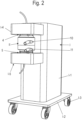
- Figure 2 shows a separator with a reusable frame I and with an exchangeable separator insert II for the centrifugal separation of a product - a suspension S - into different dense phases HP, LP.
- the separator insert II is preferably designed as a prefabricated unit.
- the separator insert II is designed as a disposable separator insert that is exchangeable or replaceable as a whole and designed as a pre-assembled unit, which is made entirely or predominantly from plastic or plastic composite materials.
- the separator insert is available separately as an example in Figure 1 and 3 It can be disposed of after processing a product batch and replaced with a new separator insert II.
- Such a separator can be useful and advantageous when processing products where it can be ruled out with a very high degree of certainty that impurities will enter the product during centrifugal processing - a flowable suspension or its phases - or where cleaning and disinfection of the separator would be very complex or even impossible.
- the frame I has a console I-1. This can - but does not have to - be mounted on a carriage I-2 with rollers I-3. Receptacles I-4 and I-5 can be arranged on the console I-1, which serve to receive and hold the separator insert II even during operation. Preferably, a first axial end of the separator insert II projects from below into the upper receptacle I-4 and a lower end of the separator insert II projects from above into the other receptacle I-5.
- Respective stator units 4a, 5a of two drive and magnetic bearing devices 4 and 5 can be arranged in the respective receptacles I-4 and I-5.
- the control and power electronics for this can be arranged in the frame I, e.g. in the console I-1.
- these mounts I-4 and I-5 protrude laterally from the console I-1 of frame I. They can be arranged on the console I-1 in a height-adjustable manner.
- Corresponding form-locking means 41a, 41b can be formed on the receptacles I-4 and I-5 and on a housing 1 of the separator insert II that does not rotate during operation in order to be able to insert the separator insert II in a rotationally fixed manner into the stator units 4a, 5a.
- the upper and lower stator units 4a, 5a can each have axes that are aligned with one another.
- the two receptacles I-4 and I-5 with the stator units 4a, 5a are arranged on the frame I-1 so as to be axially movable, in particular displaceable, relative to one another - and here, for example, also vertically.
- the receptacles I-4 and I-5 with the stator units 4a, 5a on the frame I can be moved axially apart and back towards each other in order to change the separator insert II, ie in order to be able to remove the old separator insert II from the frame I and replace it with a new one. It can also be provided that the relative distance between the receptacles I-4 and I-5 with the stator units 4a, 5a of the Bearing devices 4, 5 are adjustable in order to be able to change the separator insert II.
- the separator insert II can be fastened to the frame I in a form-fitting and/or force-fitting manner so that it cannot rotate.
- the housing 1 and the stator units 4a, 5a can have corresponding form-fitting means such as projections (e.g. pins) and recesses (e.g. holes) in order to hold the housing 1 in a form-fitting manner on the stator units and thus on the frame II.
- the corresponding form-fitting means can also be formed directly on the frame II.
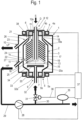
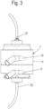
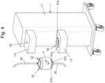
- the separator insert II of the separator has a housing 1 and a rotor 2 inserted into the housing 1 and rotatable relative to the housing 1 during operation.
- the rotor 2 has a rotation axis D. This can be aligned vertically.
- the rotor 2 of the separator insert II also has a rotatable drum 3.
- the rotor 2 is rotatably mounted at two locations axially spaced from one another in the direction of the axis of rotation with respective magnetic bearing devices 4, 5. It is preferably mounted in this way at its two axial ends.
- the separator insert has rotor units 4b, 5b of the magnetic bearing devices 4, 5.
- stator units 4a, 5a of the magnetic bearing devices 4, 5 are arranged.
- the magnetic bearing devices 4, 5 preferably act radially and axially and preferably keep the rotor 2 suspended in the housing 1 at a distance from the latter.
- the rotor units 4b, 5b can be designed essentially in the manner of inner rings made of magnets, in particular permanent magnets, and the reusable stator units 4a, 5a can be designed essentially in the manner of Outer rings can be used for axial and radial bearing of the rotor 2 (e.g. above) or alternatively for rotary drive (e.g. below).
- the rotor units 4b and/or 5b as part of the separator drive also represent a part of the rotating system or rotor.
- the rotor of the drive is a part of the drum of the centrifugal separator.
- One or both of the magnetic bearing devices 4, 5 is/are therefore preferably also used as a drive device for rotating the rotor 2 with the drum 3 in the housing 1.
- the respective magnetic bearing device forms a combined magnetic bearing and drive device.
- the magnetic bearing devices 4, 5 can be designed as axial and/or radial bearings, which support the drum 3 at its ends during operation in a cooperative manner axially and radially and keep it suspended and rotating during operation.
- the magnetic bearing devices 4 and 5 can be designed in the same or largely the same way in terms of their basic structure. In particular, only one of the two magnetic bearing devices 4, 5 can also be used as a drive device. Corresponding components of the magnetic bearings 4, 5 are thus formed on the separator insert II - on its rotor 2 - and other corresponding parts on the frame I. One or both stator units 4a, 5a can also be electrically connected to control and power electronics for controlling the electromagnetic components of the magnetic bearing devices.
- the respective magnetic bearing device 4, 5 can, for example, operate according to a combined electro- and permanent-magnetic operating principle.
- At least the lower axially acting magnetic bearing device 5 serves to keep the rotor 2 suspended axially within the housing 1 by levitation. It can have one or more first permanent magnets, for example on the underside of the rotor, and furthermore have electromagnets on a holder on the frame, which coaxially surround the permanent magnet(s).
- the rotor can be driven electromagnetically. However, a drive via rotating permanent magnets is also possible.
- Such bearing and drive devices are used, for example, by the company Levitronix for driving centrifugal pumps ( EP2 273 124 B1 ). They can also be used in the context of this document.
- a first Levitronix motor "bottom” can be used as a drive, which simultaneously magnetically supports the drum radially and axially.
- a second Levitronix motor - for example, identical in construction except for the control in operation - can be provided, which can support the rotor 2 radially and axially on the head as the magnetic bearing 4.
- the rotor speed can be variably adjusted using a control device 37 or a separate control device for the magnetic bearings 4, 5.
- the direction of rotation of the rotor 2 can also be specified and changed using the control device.
- the rotor 2 rotates. It is thus held in axial suspension and centered radially.
- the rotor 2 is preferably operated with the drum 3 at a speed of between 1,000, preferably 5,000 to 10,000, and possibly up to 20,000 revolutions per minute.
- the centrifugal forces generated by the rotation lead to the separation of a suspension to be processed into various flowable phases LP, HP of different densities, as described above, and to their discharge, as described in more detail below.
- the product batch is processed in continuous operation, which means that the phases separated from the suspension are completely discharged from the drum during operation.
- the housing 1 preferably consists of a plastic or a plastic composite material.
- the housing 1 can be cylindrical and have a cylindrical outer casing, at the ends of which two radially extending boundary walls 6, 7 (cover and base) are formed.
- the drum 3 serves for the centrifugal separation of a flowable suspension S in the centrifugal field into at least two phases LP, HP of different densities, which can be, for example, a lighter liquid phase and a heavy solid phase or a heavy liquid phase.
- the rotor 2 and its drum 3 have a vertical axis of rotation D.
- the housing 1 and the rotor 2 could also be aligned differently in space. The following description refers to the vertical alignment shown. If the orientation in space is different, the alignments change according to the new alignment. In addition, one or both outlets may be arranged differently - to be discussed later.
- the rotor 2 of the separator with the drum is also preferably made of a plastic or a plastic composite material.
- the drum 3 is preferably cylindrical and/or conical in sections. The same applies to the other elements in the rotor 2 and on the housing 1 (except for elements of the magnetic bearing devices 4, 5).
- the housing 1 is designed in the manner of a container, which is advantageously hermetically sealed except for a few openings/opening areas (which are still to be discussed). These openings are an inlet 8 in the first - here upper - axial boundary wall 6, a recirculation inlet 9 in the second - here lower - axial boundary wall 7 and two outlets 10, 11 in a peripheral outer shell or a peripheral outer wall of the housing 1.
- the drum 3 also has openings which are functionally associated with the openings of the housing.
- First and second openings of the drum 3 (which can be provided on the drum 3 in a circumferentially distributed manner, whereby the drum 3 thus has a plurality of first and second openings may be provided) serve as radial outlets 21, 22.
- Inlet pipes 12, 32 extend into two further openings 12a, 32a at the two axial ends of the drum 3 in a manner to be explained below.
- the inlet 8 is advantageously formed by a non-rotatable inlet pipe 12, one end of which projects outwards from the top of the housing 1 and which extends through the upper boundary wall 6 into the drum 3, but does not touch the drum 3.
- the inlet pipe 12 is inserted into the housing 1 in a sealed manner on the outer circumference - e.g. by welding or gluing - or, if necessary, is made in one piece with the housing as a plastic injection-molded part. It is also preferably made of plastic.
- the inlet pipe 12 passes through the housing 1 and the one magnetic bearing 4 concentrically to the axis of rotation of the rotor 2, then extends axially further within the housing 1 into the opening 12a of the rotatable drum 3 and ends there in the drum 3 with its other end - a free outlet end.
- the opening 12 - the inlet pipe - of the housing is functionally assigned to the opening 12a of the drum.
- the inlet pipe 12 opens into the drum 3 in a distributor 13 that can rotate with the drum 3.
- the distributor 13 has a tubular distributor shaft 14 and a distributor base 15.
- One or more distributor channels 16 are formed in the distributor base 15.
- a separating plate stack made up of conical separating plates 17 can be placed on the distributor 13.
- the distributor 13 and the separating plates 17 are preferably also made of plastic.
- the drum 3 has sections of different diameters so that the different dense phases can be discharged at different diameters.
- the drum 3 has at least two cylindrical sections 18, 19 of different diameters.
- One or more conical transition areas can be formed adjacent to these on the drum 3.
- the drum 3 can also be designed as a single or double cone in its central axial area on the inside (not shown here). The derivation of the heavier phase HP then occurs particularly on the largest inner diameter.
- the drum 3 can have a lower cylindrical section 20 of smaller diameter, on/in which the rotor unit 5b of the lower magnetic bearing is also formed, which merges into a conical region 20a, then here, for example, a cylindrical region 19 of larger diameter, then again a conical region 18a and then an upper cylindrical section 18 of smaller diameter, on which the rotor unit 4b of the upper magnetic bearing 4 is formed.
- outlets 21, 22 are provided in the sections 18, 19 of different diameters in the outer casing of the drum 3.
- These outlets 21, 22 can further preferably be designed as one or more openings, in particular nozzle-like openings in the outer casing of the drum 3. They are thus designed as so-called "free" outlets.
- the first outlet 21 in the section 18 of smaller diameter serves to discharge the lighter phase LP and the second outlet 22 in the section 19 of larger - here "largest" - diameter serves to discharge the heavier phase HP.
- the phases emerging from the drum 3 are collected in the housing 1 in axially offset annular collecting chambers 23, 24 of the housing 1.
- These annular collecting chambers 23, 24 are designed in such a way that the phase collected in them is directed to one of the outlets 10, 11 of the respective annular collecting chamber 23, 24. This can be achieved by having the respective outlet 10, 11 located at the lowest point of the respective annular collecting chamber 23, 24.
- the annular collecting chambers 23, 24 are open radially inwards and designed in such a way that liquid spraying out of the respective outlet 21 or 22 is essentially only sprayed into the associated annular collecting chamber 23, 24, which is located at the same axial level, during centrifugal separation.
- a further third chamber 25 which does not serve to drain a phase can optionally be formed below the second collecting ring chamber 24, a further third chamber 25 which does not serve to drain a phase can optionally be formed.
- This chamber 25 can optionally have a leakage drain (not shown here).
- the first and the second collecting ring chamber 23, 24 can be separated from each other by a first, here conical wall 26, which extends conically inwards and upwards from the outer shell of the housing 1 and ends radially in front of the drum 3 at a distance from the latter.
- the second collecting ring chamber 24 can also be limited at the bottom by a conical wall 27 which, starting from the outer shell of the housing 1, runs conically inwards and upwards and ends radially spaced from the drum 3.
- the respective product phase LP and HP is drained from the housing 1 through the respective outlet 10, 11.
- Nozzles can be provided in the area of the respective outlet 10, 11 on the outside of the housing 1 in order to be able to easily connect lines and the like. These can in turn be formed directly on the housing or attached to it with adhesive.
- the nozzles are preferably also made of plastic.
- the housing 1 can be composed of several plastic parts that are connected to one another in a sealed manner, for example by adhesive or welding.
- one of the two product phases LP, HP preferably the heavier product phase HP of the two derived product phases LP, HP, can be partially recirculated into the drum 3.
- this heavy phase HP is pumped out of the outlet 11 by a pump 28 through a line 29.
- This line 29 can be designed as a hose.
- This line can be designed as a hose, which can optionally also have a buffer container or bag on the suction side of the pump.
- branch line 30 branches off from line 29.
- This branch line 30 can also be designed as a hose. Both the branch line 30 and/or the line 29 behind (in the direction of flow) the branch to the branch line 30 can have a controllable, in particular electrically controllable, control valve 31.
- a control valve can have an open and a closed position as well as intermediate positions (half-open, etc.).
- the branch line 30 opens into the recirculation inlet 9, which can be formed at the second - here lower - end of the drum 3 and the housing 1 facing away from the inlet. In this way, a recirculation line is formed with which the heavy phase HP can be returned to the drum 3.
- the recirculation inlet 9 comprises the second inlet pipe 32, which extends analogously to the first inlet pipe 12 - but from below - through the second - here lower - radially extending boundary wall 7 into the drum 3 and ends there in a second distributor 33 and/or is connected to it, the distributor channels 34 of which extend radially.
- the second inlet pipe is also not designed to rotate and is connected to the housing 1 in a sealed manner.
- two distributors 13, 33 are provided. It is preferred that the first distributor 13 rotates with the drum 3 during operation and that the second distributor 33 does not rotate with the drum during operation.
- the phase to be recirculated - here HP - is pumped back into the drum through this.
- the second distributor 33 can be designed as a type of non-rotatable distributor disk, which can be aligned perpendicular to the axis of rotation and can also have one or more higher-level radially extending distributor channels 34, with which the returned phase HP is pumped radially outwards when entering the drum 3 and there preferably in the circumferential and rotational direction of the drum. It can be expediently provided that the distributor channels 34 in the distributor 33 run spirally with the direction of rotation during operation.
- the disk-like distributor 33 extends radially into the drum so far that it can transfer the liquid into the rotating drum 3 in such a way that no liquid escapes axially through the lower opening 32a of the drum.
- the liquid that flows out of the distributor is instead accelerated to circumferential speed in the drum by this - e.g. with ribs/channels (not shown).
- the lighter phase LP leaves the drum 3 at a radius ro. From there it flows - due to its momentum in the catch clamp 23 in a circular manner - through the upper outlet 10 into the housing 1.
- the separator is provided with its reusable components. These include the frame I and the drive and stator units 4a, 5a of the magnetic bearing devices. This also includes a control unit 37.
- a separator insert II is then provided and mounted on frame I.
- This separator insert can preferably also have at least hoses and nozzles which can be connected to further lines (not shown here) and containers such as bags, tanks, pumps and the like.
- phase HP flows radially outwards in the separation chamber of the drum 3. There the phase HP leaves the drum at a radius ru.
- the lighter phase LP flows radially inwards in the drum 3 in the separation chamber and rises upwards through a channel 38 on a shaft of the distributor. There the phase LP leaves the drum at a radius ro.
- the ratio of ro to ru and the number and size of the openings allow the radius of the separation zone between the two phases within the plate pack to be adjusted, thus allowing the flow rates of the individual phases to be coordinated.
- the light phase LP as well as the heavy phase HP are each freely discharged from the drum 3 via openings as outlets 21, 22 in continuous operation.
- a portion of the heavy phase is returned to the drum 3 via the recirculation inlet 9 and the distributor 33.
- the concentration of the heavy phase can be influenced in a simple manner and the separation process can be optimized.
- a control device 37 is used for control.
- control valve 31 can be controlled as part of a control system, for which a parameter - here the heavy phase HP with the measuring device 35 - is measured. This is indicated here by a type of connection 36 to the control device 37.
- a parameter here of the second phase HP e.g. its density, can be determined, whereby the control valve can then be fully or partially opened and closed in a controlled manner with the control device 37 using a control algorithm (dashed lines - connection 36).
- a measurement can be taken, for example a density measurement (measuring device 35) of the heavy phase at the outlet of the centrifuge. This measured value is sent to the control device 37 (dashed line) and compared with a target value. If a specified target value, e.g. a density target value, has not yet been reached, part of the separated heavy phase HP can be fed back into the separation chamber of the drum 3 via a control valve. This process makes it possible to set the actual value of the density of the separated heavy phase HP greater than or equal to a specified target value.
- This regulation can be carried out, for example, with a PID controller.
- control could alternatively be based on other measured values, such as turbidity, conductivity, volume flow, pH value. It would also be conceivable to set the value using a quantity or mass balance and thus set a desired solids concentration. Other controls can be based on the flow rate or the feed rate or the drum speed and/or combinations of these parameters.
- the inlet quantity can be changed or the drum speed can be varied in a suitable manner.
- the measurements proposed for the heavy phase HP can alternatively or additionally be carried out in the process for the light phase LP. If, for example, turbidity is detected in the light phase, this can be used as a control variable for a Adjustment of the feed quantity or a suitable adjustment of the drum speed can be used.
- the position of the rotation axis D can be freely selected in this design, as the magnetic bearing arrangement of the two magnetic bearing devices 4 and 5 allows this.
- the position of the rotation axis D can be vertical or horizontal or can have any inclination.
- the free flow of the light phase LP must be structurally adapted depending on the position of the rotation axis D. If one of the phases HP, LP is pumped out, this is not absolutely necessary.
- Cell separations in the pharmaceutical industry are one possible application of the separator according to the invention.
- the performance range is intended for the processing of broths from fermenters in the size range of 100 l-4000 l as well as for laboratory applications.
- separators are used are also conceivable: chemicals, pharmaceuticals, dairy technology, renewable raw materials, oil and gas, beverage technology, mineral oil, etc.
- the form-locking means 41a, 41b of the separator insert and the corresponding form-locking means provided on the frame I can be provided only on one side between the frame I and the separator insert II, thus also enabling axial and rotational locking of the separator insert II relative to the frame I. This reduces, among other things, the complexity of the structure.
Landscapes
- Centrifugal Separators (AREA)
- Electrophonic Musical Instruments (AREA)
- Refuse Collection And Transfer (AREA)
Applications Claiming Priority (2)
| Application Number | Priority Date | Filing Date | Title |
|---|---|---|---|
| DE102020121420.0A DE102020121420A1 (de) | 2020-08-14 | 2020-08-14 | Separator |
| PCT/EP2021/071876 WO2022033952A1 (de) | 2020-08-14 | 2021-08-05 | Separatoreinsatz und separator |
Publications (2)
| Publication Number | Publication Date |
|---|---|
| EP4196282A1 EP4196282A1 (de) | 2023-06-21 |
| EP4196282B1 true EP4196282B1 (de) | 2024-10-02 |
Family
ID=77411708
Family Applications (1)
| Application Number | Title | Priority Date | Filing Date |
|---|---|---|---|
| EP21758090.1A Active EP4196282B1 (de) | 2020-08-14 | 2021-08-05 | Separatoreinsatz und separator |
Country Status (15)
| Country | Link |
|---|---|
| US (1) | US20230294110A1 (pl) |
| EP (1) | EP4196282B1 (pl) |
| JP (1) | JP7728851B2 (pl) |
| KR (1) | KR20230048518A (pl) |
| CN (1) | CN116096501A (pl) |
| AU (1) | AU2021324022A1 (pl) |
| BR (1) | BR112022026863A2 (pl) |
| CA (1) | CA3184135A1 (pl) |
| DE (1) | DE102020121420A1 (pl) |
| DK (1) | DK4196282T3 (pl) |
| ES (1) | ES2994676T3 (pl) |
| FI (1) | FI4196282T3 (pl) |
| IL (1) | IL300317B1 (pl) |
| PL (1) | PL4196282T3 (pl) |
| WO (1) | WO2022033952A1 (pl) |
Families Citing this family (3)
| Publication number | Priority date | Publication date | Assignee | Title |
|---|---|---|---|---|
| AU2024212294A1 (en) * | 2023-01-29 | 2025-08-28 | Renovo Concepts, Inc. | Fluid collection canister for use with sub-atmospheric pressure pump |
| DE102024121025A1 (de) * | 2024-07-24 | 2026-01-29 | Gea Westfalia Separator Group Gmbh | Set von Separatoreinsätzen für einen Separator und Separator |
| CN120861252B (zh) * | 2025-09-26 | 2025-12-09 | 济南安地冶金机械设备有限公司 | 一种中心进料的磨机动态分离器 |
Family Cites Families (15)
| Publication number | Priority date | Publication date | Assignee | Title |
|---|---|---|---|---|
| US3967777A (en) * | 1973-09-10 | 1976-07-06 | Exxon Research And Engineering Company | Apparatus for the treatment of tar sand froth |
| SE462077B (sv) * | 1986-03-12 | 1990-05-07 | Alfa Laval Separation Ab | Centrifugalseparator med sluten aaterfoering av tungkomponent |
| GB9703685D0 (en) * | 1997-02-21 | 1997-04-09 | Glacier Metal Co Ltd | Centrifugal separator |
| SE514774C2 (sv) * | 1998-12-21 | 2001-04-23 | Alfa Laval Ab | Reglerutrustning för centrifugalseparator samt sätt att reglera en separeringsoperation |
| US20030114289A1 (en) | 2001-11-27 | 2003-06-19 | Merino Sandra Patricia | Centrifuge with removable core for scalable centrifugation |
| EP2273124B1 (de) | 2009-07-06 | 2015-02-25 | Levitronix GmbH | Zentrifugalpumpe und Verfahren zum Ausgleichen des axialen Schubs in einer Zentrifugalpumpe |
| SE534773C2 (sv) * | 2010-04-09 | 2011-12-13 | Alfa Laval Corp Ab | Centrifugalseparator anordnad inuti en förbränningsmotor |
| CN104540596A (zh) * | 2012-02-02 | 2015-04-22 | 帕尔技术英国有限公司 | 离心分离系统和相关方法 |
| DE102012105499A1 (de) | 2012-06-25 | 2014-01-02 | Gea Mechanical Equipment Gmbh | Separator |
| CA2878645C (en) | 2014-01-22 | 2017-02-21 | Alfa Wassermann, Inc. | Centrifugation systems with non-contact seal assemblies |
| CN204769182U (zh) * | 2015-07-16 | 2015-11-18 | 南京中船绿洲机器有限公司 | 一种碟式分离机控制阀 |
| DE102017128027A1 (de) * | 2017-11-27 | 2019-05-29 | Gea Mechanical Equipment Gmbh | Separator |
| CN207745987U (zh) * | 2017-12-25 | 2018-08-21 | 江苏巨能机械有限公司 | 三相碟式分离机 |
| EP3666394A1 (en) * | 2018-12-10 | 2020-06-17 | Alfa Laval Corporate AB | Modular centrifugal separator and base unit thereof and system |
| CN112221721B (zh) * | 2020-08-20 | 2022-10-14 | 南京中船绿洲机器有限公司 | 一种碟式分离机 |
-
2020
- 2020-08-14 DE DE102020121420.0A patent/DE102020121420A1/de active Pending
-
2021
- 2021-08-05 JP JP2023505775A patent/JP7728851B2/ja active Active
- 2021-08-05 BR BR112022026863A patent/BR112022026863A2/pt unknown
- 2021-08-05 CN CN202180056622.4A patent/CN116096501A/zh active Pending
- 2021-08-05 CA CA3184135A patent/CA3184135A1/en active Pending
- 2021-08-05 IL IL300317A patent/IL300317B1/en unknown
- 2021-08-05 EP EP21758090.1A patent/EP4196282B1/de active Active
- 2021-08-05 PL PL21758090.1T patent/PL4196282T3/pl unknown
- 2021-08-05 FI FIEP21758090.1T patent/FI4196282T3/fi active
- 2021-08-05 AU AU2021324022A patent/AU2021324022A1/en active Pending
- 2021-08-05 US US18/021,062 patent/US20230294110A1/en active Pending
- 2021-08-05 ES ES21758090T patent/ES2994676T3/es active Active
- 2021-08-05 KR KR1020237007078A patent/KR20230048518A/ko active Pending
- 2021-08-05 DK DK21758090.1T patent/DK4196282T3/da active
- 2021-08-05 WO PCT/EP2021/071876 patent/WO2022033952A1/de not_active Ceased
Also Published As
| Publication number | Publication date |
|---|---|
| DK4196282T3 (da) | 2024-12-16 |
| DE102020121420A1 (de) | 2022-02-17 |
| ES2994676T3 (en) | 2025-01-29 |
| EP4196282A1 (de) | 2023-06-21 |
| BR112022026863A2 (pt) | 2023-02-23 |
| PL4196282T3 (pl) | 2025-02-24 |
| CN116096501A (zh) | 2023-05-09 |
| KR20230048518A (ko) | 2023-04-11 |
| JP2023538817A (ja) | 2023-09-12 |
| CA3184135A1 (en) | 2022-02-17 |
| IL300317A (en) | 2023-04-01 |
| AU2021324022A1 (en) | 2023-02-02 |
| WO2022033952A1 (de) | 2022-02-17 |
| US20230294110A1 (en) | 2023-09-21 |
| IL300317B1 (en) | 2025-12-01 |
| JP7728851B2 (ja) | 2025-08-25 |
| FI4196282T3 (fi) | 2024-12-05 |
Similar Documents
| Publication | Publication Date | Title |
|---|---|---|
| EP4196284B1 (de) | Separatoreinsatz, separator und verfahren zum wechseln eines separatoreinsatzes | |
| EP4196282B1 (de) | Separatoreinsatz und separator | |
| EP1418998B8 (de) | Verfahren zur abtrennung von blutplasmapartikeln aus einer blutplasmasuspension | |
| EP3930909B1 (de) | Separator | |
| EP3717132A1 (de) | Separator | |
| WO2023036786A1 (de) | Separatoreinsatz, separator und verfahren zum wechseln eines separatoreinsatzes | |
| EP4196285B1 (de) | Separatoreinsatz und separator | |
| EP4499318B1 (de) | Separator | |
| DE102021123178A1 (de) | Separatoreinsatz, Separator und Verfahren zum Wechseln eines Separatoreinsatzes | |
| WO2024033325A1 (de) | Trennanlage zum trennen einer suspension | |
| EP1508377B1 (de) | Separator | |
| WO2005007296A1 (de) | Zentrifuge mit mehreren schleudertrommeln mit tellerpaketen | |
| EP4032615A1 (de) | Rührwerksmühle | |
| DE202023100651U1 (de) | Trennanlage zum Trennen einer Suspension | |
| WO2024251477A1 (de) | Trennanlage zum trennen einer suspension | |
| DE202024102397U1 (de) | Trennanlage zum Trennen einer Suspension | |
| WO2004033105A1 (de) | Filterzentrifuge mit aufnahme für verschiedene filtereinheiten | |
| DE102024121025A1 (de) | Set von Separatoreinsätzen für einen Separator und Separator | |
| DE102025127994A1 (de) | Separatoreinsatz sowie Separator mit einem solchen Separatoreinsatz | |
| DE102024102414A1 (de) | Zentrifuge mit einer Schleudertrommel mit einer Kühleinrichtung | |
| DE102016115557A1 (de) | Zentrifuge mit einer Schälscheibe |
Legal Events
| Date | Code | Title | Description |
|---|---|---|---|
| STAA | Information on the status of an ep patent application or granted ep patent |
Free format text: STATUS: UNKNOWN |
|
| STAA | Information on the status of an ep patent application or granted ep patent |
Free format text: STATUS: THE INTERNATIONAL PUBLICATION HAS BEEN MADE |
|
| PUAI | Public reference made under article 153(3) epc to a published international application that has entered the european phase |
Free format text: ORIGINAL CODE: 0009012 |
|
| STAA | Information on the status of an ep patent application or granted ep patent |
Free format text: STATUS: REQUEST FOR EXAMINATION WAS MADE |
|
| 17P | Request for examination filed |
Effective date: 20230215 |
|
| AK | Designated contracting states |
Kind code of ref document: A1 Designated state(s): AL AT BE BG CH CY CZ DE DK EE ES FI FR GB GR HR HU IE IS IT LI LT LU LV MC MK MT NL NO PL PT RO RS SE SI SK SM TR |
|
| DAV | Request for validation of the european patent (deleted) | ||
| DAX | Request for extension of the european patent (deleted) | ||
| GRAP | Despatch of communication of intention to grant a patent |
Free format text: ORIGINAL CODE: EPIDOSNIGR1 |
|
| STAA | Information on the status of an ep patent application or granted ep patent |
Free format text: STATUS: GRANT OF PATENT IS INTENDED |
|
| INTG | Intention to grant announced |
Effective date: 20240521 |
|
| GRAS | Grant fee paid |
Free format text: ORIGINAL CODE: EPIDOSNIGR3 |
|
| P01 | Opt-out of the competence of the unified patent court (upc) registered |
Free format text: CASE NUMBER: APP_39667/2024 Effective date: 20240703 |
|
| GRAA | (expected) grant |
Free format text: ORIGINAL CODE: 0009210 |
|
| STAA | Information on the status of an ep patent application or granted ep patent |
Free format text: STATUS: THE PATENT HAS BEEN GRANTED |
|
| AK | Designated contracting states |
Kind code of ref document: B1 Designated state(s): AL AT BE BG CH CY CZ DE DK EE ES FI FR GB GR HR HU IE IS IT LI LT LU LV MC MK MT NL NO PL PT RO RS SE SI SK SM TR |
|
| REG | Reference to a national code |
Ref country code: GB Ref legal event code: FG4D Free format text: NOT ENGLISH |
|
| REG | Reference to a national code |
Ref country code: CH Ref legal event code: EP |
|
| REG | Reference to a national code |
Ref country code: IE Ref legal event code: FG4D Free format text: LANGUAGE OF EP DOCUMENT: GERMAN |
|
| REG | Reference to a national code |
Ref country code: DE Ref legal event code: R096 Ref document number: 502021005333 Country of ref document: DE |
|
| REG | Reference to a national code |
Ref country code: NL Ref legal event code: FP |
|
| REG | Reference to a national code |
Ref country code: SE Ref legal event code: TRGR |
|
| REG | Reference to a national code |
Ref country code: FI Ref legal event code: FGE |
|
| REG | Reference to a national code |
Ref country code: DK Ref legal event code: T3 Effective date: 20241212 |
|
| REG | Reference to a national code |
Ref country code: SK Ref legal event code: T3 Ref document number: E 45366 Country of ref document: SK |
|
| REG | Reference to a national code |
Ref country code: LT Ref legal event code: MG9D |
|
| REG | Reference to a national code |
Ref country code: ES Ref legal event code: FG2A Ref document number: 2994676 Country of ref document: ES Kind code of ref document: T3 Effective date: 20250129 |
|
| PG25 | Lapsed in a contracting state [announced via postgrant information from national office to epo] |
Ref country code: HR Free format text: LAPSE BECAUSE OF FAILURE TO SUBMIT A TRANSLATION OF THE DESCRIPTION OR TO PAY THE FEE WITHIN THE PRESCRIBED TIME-LIMIT Effective date: 20241002 Ref country code: PT Free format text: LAPSE BECAUSE OF FAILURE TO SUBMIT A TRANSLATION OF THE DESCRIPTION OR TO PAY THE FEE WITHIN THE PRESCRIBED TIME-LIMIT Effective date: 20250203 Ref country code: IS Free format text: LAPSE BECAUSE OF FAILURE TO SUBMIT A TRANSLATION OF THE DESCRIPTION OR TO PAY THE FEE WITHIN THE PRESCRIBED TIME-LIMIT Effective date: 20250202 |
|
| PG25 | Lapsed in a contracting state [announced via postgrant information from national office to epo] |
Ref country code: BG Free format text: LAPSE BECAUSE OF FAILURE TO SUBMIT A TRANSLATION OF THE DESCRIPTION OR TO PAY THE FEE WITHIN THE PRESCRIBED TIME-LIMIT Effective date: 20241002 |
|
| PG25 | Lapsed in a contracting state [announced via postgrant information from national office to epo] |
Ref country code: NO Free format text: LAPSE BECAUSE OF FAILURE TO SUBMIT A TRANSLATION OF THE DESCRIPTION OR TO PAY THE FEE WITHIN THE PRESCRIBED TIME-LIMIT Effective date: 20250102 |
|
| PG25 | Lapsed in a contracting state [announced via postgrant information from national office to epo] |
Ref country code: LV Free format text: LAPSE BECAUSE OF FAILURE TO SUBMIT A TRANSLATION OF THE DESCRIPTION OR TO PAY THE FEE WITHIN THE PRESCRIBED TIME-LIMIT Effective date: 20241002 Ref country code: GR Free format text: LAPSE BECAUSE OF FAILURE TO SUBMIT A TRANSLATION OF THE DESCRIPTION OR TO PAY THE FEE WITHIN THE PRESCRIBED TIME-LIMIT Effective date: 20250103 |
|
| PG25 | Lapsed in a contracting state [announced via postgrant information from national office to epo] |
Ref country code: RS Free format text: LAPSE BECAUSE OF FAILURE TO SUBMIT A TRANSLATION OF THE DESCRIPTION OR TO PAY THE FEE WITHIN THE PRESCRIBED TIME-LIMIT Effective date: 20250102 |
|
| PG25 | Lapsed in a contracting state [announced via postgrant information from national office to epo] |
Ref country code: SM Free format text: LAPSE BECAUSE OF FAILURE TO SUBMIT A TRANSLATION OF THE DESCRIPTION OR TO PAY THE FEE WITHIN THE PRESCRIBED TIME-LIMIT Effective date: 20241002 |
|
| REG | Reference to a national code |
Ref country code: DE Ref legal event code: R097 Ref document number: 502021005333 Country of ref document: DE |
|
| REG | Reference to a national code |
Ref country code: CH Ref legal event code: PK Free format text: BERICHTIGUNGEN |
|
| PG25 | Lapsed in a contracting state [announced via postgrant information from national office to epo] |
Ref country code: EE Free format text: LAPSE BECAUSE OF FAILURE TO SUBMIT A TRANSLATION OF THE DESCRIPTION OR TO PAY THE FEE WITHIN THE PRESCRIBED TIME-LIMIT Effective date: 20241002 |
|
| PG25 | Lapsed in a contracting state [announced via postgrant information from national office to epo] |
Ref country code: RO Free format text: LAPSE BECAUSE OF FAILURE TO SUBMIT A TRANSLATION OF THE DESCRIPTION OR TO PAY THE FEE WITHIN THE PRESCRIBED TIME-LIMIT Effective date: 20241002 |
|
| RIN2 | Information on inventor provided after grant (corrected) |
Inventor name: GOEHMANN, RUEDIGER Inventor name: HELMRICH, KAI Inventor name: QUITER, KATHRIN Inventor name: SCHULZ, ANDREAS Inventor name: BURKART, JUERG Inventor name: STOECKLI, SIMON |
|
| PLBE | No opposition filed within time limit |
Free format text: ORIGINAL CODE: 0009261 |
|
| STAA | Information on the status of an ep patent application or granted ep patent |
Free format text: STATUS: NO OPPOSITION FILED WITHIN TIME LIMIT |
|
| 26N | No opposition filed |
Effective date: 20250703 |
|
| PGFP | Annual fee paid to national office [announced via postgrant information from national office to epo] |
Ref country code: NL Payment date: 20250826 Year of fee payment: 5 |
|
| PGFP | Annual fee paid to national office [announced via postgrant information from national office to epo] |
Ref country code: ES Payment date: 20250902 Year of fee payment: 5 Ref country code: FI Payment date: 20250829 Year of fee payment: 5 |
|
| PGFP | Annual fee paid to national office [announced via postgrant information from national office to epo] |
Ref country code: DE Payment date: 20250828 Year of fee payment: 5 Ref country code: DK Payment date: 20250822 Year of fee payment: 5 |
|
| PGFP | Annual fee paid to national office [announced via postgrant information from national office to epo] |
Ref country code: IT Payment date: 20250827 Year of fee payment: 5 Ref country code: TR Payment date: 20250729 Year of fee payment: 5 Ref country code: PL Payment date: 20250721 Year of fee payment: 5 |
|
| PGFP | Annual fee paid to national office [announced via postgrant information from national office to epo] |
Ref country code: GB Payment date: 20250827 Year of fee payment: 5 Ref country code: BE Payment date: 20250822 Year of fee payment: 5 |
|
| PGFP | Annual fee paid to national office [announced via postgrant information from national office to epo] |
Ref country code: FR Payment date: 20250826 Year of fee payment: 5 Ref country code: AT Payment date: 20251020 Year of fee payment: 5 |
|
| PGFP | Annual fee paid to national office [announced via postgrant information from national office to epo] |
Ref country code: SE Payment date: 20250827 Year of fee payment: 5 Ref country code: CH Payment date: 20250901 Year of fee payment: 5 |
|
| PGFP | Annual fee paid to national office [announced via postgrant information from national office to epo] |
Ref country code: IE Payment date: 20250824 Year of fee payment: 5 Ref country code: CZ Payment date: 20250718 Year of fee payment: 5 |
|
| PGFP | Annual fee paid to national office [announced via postgrant information from national office to epo] |
Ref country code: SK Payment date: 20250718 Year of fee payment: 5 |