EP4194977A2 - Lineares transportsystem und verfahren zur steuerung eines linearen transportsystems - Google Patents
Lineares transportsystem und verfahren zur steuerung eines linearen transportsystems Download PDFInfo
- Publication number
- EP4194977A2 EP4194977A2 EP22179584.2A EP22179584A EP4194977A2 EP 4194977 A2 EP4194977 A2 EP 4194977A2 EP 22179584 A EP22179584 A EP 22179584A EP 4194977 A2 EP4194977 A2 EP 4194977A2
- Authority
- EP
- European Patent Office
- Prior art keywords
- movable elements
- movable element
- movable
- track
- sensors
- Prior art date
- Legal status (The legal status is an assumption and is not a legal conclusion. Google has not performed a legal analysis and makes no representation as to the accuracy of the status listed.)
- Withdrawn
Links
Images





Classifications
-
- G—PHYSICS
- G05—CONTROLLING; REGULATING
- G05B—CONTROL OR REGULATING SYSTEMS IN GENERAL; FUNCTIONAL ELEMENTS OF SUCH SYSTEMS; MONITORING OR TESTING ARRANGEMENTS FOR SUCH SYSTEMS OR ELEMENTS
- G05B19/00—Program-control systems
- G05B19/02—Program-control systems electric
- G05B19/18—Numerical control [NC], i.e. automatically operating machines, in particular machine tools, e.g. in a manufacturing environment, so as to execute positioning, movement or co-ordinated operations by means of program data in numerical form
- G05B19/19—Numerical control [NC], i.e. automatically operating machines, in particular machine tools, e.g. in a manufacturing environment, so as to execute positioning, movement or co-ordinated operations by means of program data in numerical form characterised by positioning or contouring control systems, e.g. to control position from one programmed point to another or to control movement along a programmed continuous path
-
- B—PERFORMING OPERATIONS; TRANSPORTING
- B65—CONVEYING; PACKING; STORING; HANDLING THIN OR FILAMENTARY MATERIAL
- B65G—TRANSPORT OR STORAGE DEVICES, e.g. CONVEYORS FOR LOADING OR TIPPING, SHOP CONVEYOR SYSTEMS OR PNEUMATIC TUBE CONVEYORS
- B65G43/00—Control devices, e.g. for safety, warning or fault-correcting
- B65G43/08—Control devices operated by article or material being fed, conveyed or discharged
-
- B—PERFORMING OPERATIONS; TRANSPORTING
- B65—CONVEYING; PACKING; STORING; HANDLING THIN OR FILAMENTARY MATERIAL
- B65G—TRANSPORT OR STORAGE DEVICES, e.g. CONVEYORS FOR LOADING OR TIPPING, SHOP CONVEYOR SYSTEMS OR PNEUMATIC TUBE CONVEYORS
- B65G43/00—Control devices, e.g. for safety, warning or fault-correcting
- B65G43/02—Control devices, e.g. for safety, warning or fault-correcting detecting dangerous physical condition of load carriers, e.g. for interrupting the drive in the event of overheating
-
- G—PHYSICS
- G05—CONTROLLING; REGULATING
- G05B—CONTROL OR REGULATING SYSTEMS IN GENERAL; FUNCTIONAL ELEMENTS OF SUCH SYSTEMS; MONITORING OR TESTING ARRANGEMENTS FOR SUCH SYSTEMS OR ELEMENTS
- G05B19/00—Program-control systems
- G05B19/02—Program-control systems electric
- G05B19/18—Numerical control [NC], i.e. automatically operating machines, in particular machine tools, e.g. in a manufacturing environment, so as to execute positioning, movement or co-ordinated operations by means of program data in numerical form
- G05B19/406—Numerical control [NC], i.e. automatically operating machines, in particular machine tools, e.g. in a manufacturing environment, so as to execute positioning, movement or co-ordinated operations by means of program data in numerical form characterised by monitoring or safety
- G05B19/4061—Avoiding collision or forbidden zones
-
- G—PHYSICS
- G05—CONTROLLING; REGULATING
- G05B—CONTROL OR REGULATING SYSTEMS IN GENERAL; FUNCTIONAL ELEMENTS OF SUCH SYSTEMS; MONITORING OR TESTING ARRANGEMENTS FOR SUCH SYSTEMS OR ELEMENTS
- G05B19/00—Program-control systems
- G05B19/02—Program-control systems electric
- G05B19/18—Numerical control [NC], i.e. automatically operating machines, in particular machine tools, e.g. in a manufacturing environment, so as to execute positioning, movement or co-ordinated operations by means of program data in numerical form
- G05B19/416—Numerical control [NC], i.e. automatically operating machines, in particular machine tools, e.g. in a manufacturing environment, so as to execute positioning, movement or co-ordinated operations by means of program data in numerical form characterised by control of velocity, acceleration or deceleration
-
- B—PERFORMING OPERATIONS; TRANSPORTING
- B65—CONVEYING; PACKING; STORING; HANDLING THIN OR FILAMENTARY MATERIAL
- B65G—TRANSPORT OR STORAGE DEVICES, e.g. CONVEYORS FOR LOADING OR TIPPING, SHOP CONVEYOR SYSTEMS OR PNEUMATIC TUBE CONVEYORS
- B65G54/00—Non-mechanical conveyors not otherwise provided for
- B65G54/02—Non-mechanical conveyors not otherwise provided for electrostatic, electric, or magnetic
-
- G—PHYSICS
- G05—CONTROLLING; REGULATING
- G05B—CONTROL OR REGULATING SYSTEMS IN GENERAL; FUNCTIONAL ELEMENTS OF SUCH SYSTEMS; MONITORING OR TESTING ARRANGEMENTS FOR SUCH SYSTEMS OR ELEMENTS
- G05B19/00—Program-control systems
- G05B19/02—Program-control systems electric
- G05B19/418—Total factory control, i.e. centrally controlling a plurality of machines, e.g. direct or distributed numerical control [DNC], flexible manufacturing systems [FMS], integrated manufacturing systems [IMS] or computer integrated manufacturing [CIM]
- G05B19/4189—Total factory control, i.e. centrally controlling a plurality of machines, e.g. direct or distributed numerical control [DNC], flexible manufacturing systems [FMS], integrated manufacturing systems [IMS] or computer integrated manufacturing [CIM] characterised by the transport system
- G05B19/41895—Total factory control, i.e. centrally controlling a plurality of machines, e.g. direct or distributed numerical control [DNC], flexible manufacturing systems [FMS], integrated manufacturing systems [IMS] or computer integrated manufacturing [CIM] characterised by the transport system using automatic guided vehicles [AGV]
-
- G—PHYSICS
- G05—CONTROLLING; REGULATING
- G05B—CONTROL OR REGULATING SYSTEMS IN GENERAL; FUNCTIONAL ELEMENTS OF SUCH SYSTEMS; MONITORING OR TESTING ARRANGEMENTS FOR SUCH SYSTEMS OR ELEMENTS
- G05B2219/00—Program-control systems
- G05B2219/30—Nc systems
- G05B2219/41—Servomotor, servo controller till figures
- G05B2219/41327—Linear induction motor
Definitions
- Embodiments of the disclosure relate to a linear transport system and a method for controlling the linear transport system.
- each driver in each of the plurality of sensor structures has a data storage unit, a sensor position calculation unit, and a position specifying unit.
- the data storage unit stores, as first sensor interval data, the interval between the sensor of the sensor structure to which it belongs and the sensor of the sensor structure located upstream in the slider movement direction.
- the sensor position calculation unit calculates sensor position data of a sensor constituting a sensor structure to which it belongs based on first sensor interval data stored in a data storage unit.
- the position specifying unit specifies the position of the slider based on the addition data obtained by adding the sensor position data from the sensor position calculation unit and the detection data from the sensor constituting the sensor structure to which the position specifying unit belongs.
- the sensor position calculation unit calculates sensor position data by cumulatively adding a plurality of first sensor interval data from a sensor constituting an origin to its own sensor.
- the sensor position data cannot be calculated without using not only the first sensor interval data held by the sensor structure to which the sensor structure belongs but also the first sensor interval data held by a plurality of other sensor structures, there is a possibility that the processing speed becomes slow, the position specification of the slider is delayed, and the reliability is lowered.
- a linear transport system includes a stator having a track, a plurality of movable elements movable along the track, a plurality of scales provided on the plurality of movable elements, respectively, a plurality of sensors provided along the track of the stator at respective intervals, a parameter recording unit, and a position calculation unit.
- the stator includes a plurality of coils provided along the track.
- Each of the plurality of movable elements has a magnet.
- the plurality of sensors is configured to detect the plurality of movable elements to obtain scale positions of the plurality of scales.
- the parameter recording unit is configured to memorize first cumulative values each corresponding to a corresponding sensor among the plurality of sensors.
- Each of the first cumulative values is obtained by accumulating, from a reference position to the corresponding sensor, error correction values based on which errors between the respective intervals and measured values of the respective intervals are corrected.
- the position calculation unit is configured to calculate a position of a detected movable element among the plurality of movable elements based on detection data of a detecting sensor among the plurality of sensors that has detected the detected movable element and based on the first cumulative value corresponding to the detecting sensor.
- a linear transport system includes a stator having a track, a plurality of movable elements movable along the track, a plurality of scales provided on the plurality of movable elements, respectively, a plurality of sensors provided along the track of the stator at respective intervals, a plurality of first controllers, and a second controller connected to the plurality of first controllers to control positions of the plurality of movable elements.
- the stator includes a plurality of coils provided along the track. Each of the plurality of movable elements has a magnet.
- the plurality of sensors is configured to detect the plurality of movable elements to obtain scale positions of the plurality of scales.
- Each of the plurality of first controllers is configured to control group coils among the plurality of coils which are provided in a partial region of the track of the stator.
- the second controller includes a collision prevention processing unit to prevent a collision by monitoring a distance between the plurality of movable elements based on detection data of the plurality of sensors.
- the plurality of first controllers has an emergency stop processing unit configured to determine whether two or more of the plurality of movable elements exist within the respective intervals based on the detection data of the plurality of sensors, and configured to stop the plurality of movable elements when the plurality of first controllers determines that the two or more movable elements exist within the respective intervals.
- a method for controlling a linear transport system includes providing a stator which includes a track and a plurality of coils provided along the track; providing a plurality of movable elements movable along the track, each of the plurality of movable elements having a magnet; providing a plurality of scales on the plurality of movable elements, respectively; providing a plurality of sensors along the track of the stator at respective intervals, the plurality of sensors detecting the plurality of movable elements to obtain scale positions of the plurality of scales; accumulating, from a reference position to a corresponding sensor among the plurality of sensors, to obtain first cumulative values, error correction values based on which errors between the respective intervals and measured values of the respective intervals are corrected; memorizing the first cumulative values each corresponding to the corresponding sensor; and calculating a position of a detected movable element among the plurality of movable elements based on detection data of a detecting sensor among the plurality of sensors that has detected the detected the detected
- a method for controlling a linear transport system includes providing a stator which includes a track and a plurality of coils provided along the track; providing a plurality of movable elements movable along the track, each of the plurality of movable elements having a magnet; providing a plurality of scales on the plurality of movable elements, respectively; providing a plurality of sensors along the track of the stator at respective intervals, the plurality of sensors detecting the plurality of movable elements to obtain scale positions of the plurality of scales; providing a plurality of first controllers each of which is configured to control group coils among the plurality of coils which are provided in a partial region of the track of the stator; determining, by the plurality of first controllers, whether two or more of the plurality of movable elements exist within the respective intervals based on the detection data of the plurality of sensors; stopping the plurality of movable elements when the plurality of first controllers determine that the two or more movable elements exist
- FIG. 1 is a diagram conceptually showing an example of the overall configuration of the linear transport system according to the embodiment
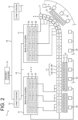
- FIG. 2 is a diagram conceptually showing a part of the configuration of the control system of the linear transport system according to the embodiment by extracting the part.
- the linear transport system 1 has a stator 3 and a plurality of movable elements (an example of "a plurality of carriers") 5.
- the stator 3 has a track.
- the track has, for example, a loop shape.
- Each of the movable elements 5 moves along the track of the stator 3 to convey the workpiece W.
- the stator 3 is provided with a plurality of coils, and each of the movable elements 5 is provided with a magnet.
- the linear transport system 1 is a so-called moving magnet type.
- Each movable element 5 may have a uniform length in the moving direction, or may include a plurality of movable elements 5 having different lengths in the moving direction.
- a processing device R1 for processing or assembling the workpiece W for example, a processing device R1 for processing or assembling the workpiece W, a carry-in device R2 for carrying in the workpiece W, and a carry-out device R3 for carrying out the workpiece W are disposed.
- the linear transport system 1 conveys the workpiece W by moving the movable element 5 in the direction of the arrow 7 in FIG. 1 , and performs processing, assembly, and the like.
- the linear transport system 1 includes a multi-axis amplifier 11, a linear controller 13, and an operation controller 15.
- a multi-axis amplifier 11 As shown in FIG. 2 , the linear transport system 1 includes a multi-axis amplifier 11, a linear controller 13, and an operation controller 15.
- FIG. 2 some sections of the stator 3 are illustrated, but other sections of the stator 3 have the same configuration.
- the multi-axis amplifier 11 controls the energization of the coils in a part of the section of the stator 3.
- the multi-axis amplifier 11 supplies electric power to, for example, three sets of coils 17 when one set of coils 17 is composed of, for example, a U-phase coil 17U, a V-phase coil 17 v and a W-phase coil 17W provided in the stator 3.
- the multi-axis amplifier 11 controls the energization of each of the three sets of coils 17 independently, and controls the position or speed of the movable element 5.
- a plurality of multi-axis amplifiers 11 (for example, one for each of three sets of coils 17) are provided.
- a plurality of multi-axis amplifiers 11 for energizing coils 17 belonging to a common stator 3 are connected to each other via a communication cable 19, and can transmit and receive data by, for example, SPI (Serial Peripheral Interface) communication.
- SPI Serial Peripheral Interface
- each movable element 5 has a magnet 21 which is a permanent magnet and a scale 23.
- the scale 23 is provided with a movable element ID for identifying each movable element 5 and a scale for detecting the machine coordinate position of each movable element 5.
- a plurality of sensor heads 25 are arranged along the stator 3 at predetermined intervals. The predetermined interval is set to be shorter than the length of the scale 23 so that the movable element 5 can be detected at any position, for example.
- Each sensor head 25 detects the movable element ID and scale of the scale 23 of the movable element 5 facing each other.
- Each multi-axis amplifier 11 receives detection data of the three sensor heads 25.
- Each multi-axis amplifier 11 shares the detection data of the sensor head 25 with an adjacent multi-axis amplifier 11 (multi-axis amplifier 11 corresponding to front and rear in the moving direction) via the communication cable 19. This makes it possible to smoothly switch the control of the multi-axis amplifier 11 in accordance with the movement of the movable element 5.
- the linear controller 13 (an example of “second control circuitry” or “second controller”) is connected to a plurality of multi-axis amplifiers 11 corresponding to the common stator 3 via a communication cable 19.
- the linear controller 13 controls the positions of a plurality of movable elements 5 located on the loop of the stator 3.
- the linear transport system 1 has a plurality of linear controllers 13.
- the linear controller 13 converts the position command for designating the position of each movable element 5 on the loop in the stator 3 received from the operation controller 15 into a position command for each section of the stator 3 corresponding to each multi-axis amplifier 11, and transmits the position command to each multi-axis amplifier 11.
- the linear controller 13 generates a speed command for preventing a collision between the movable elements 5 on the loop of the stator 3, and transmits it to each multi-axis amplifier 11.
- the operation controller 15 is connected to a plurality of linear controllers 13 via a communication cable 19.
- the operation controller 15 controls the positions of the plurality of movable elements 5 located on the loop of the stator 3, that is, the positions of all the movable elements 5 provided in the linear transport system 1.
- the operation controller 15 transmits a position command for designating the position of each movable element 5 on the loop in the stator 3 to each linear controller 13.
- the linear controller 13 and the operation controller 15 are a control apparatus having, for example, a calculation device (CPU), a recording device, an input device and the like.
- a calculation device CPU
- a recording device for example, a recording device, an input device and the like.
- the linear controller 13 and the operation controller 15 for example, a general-purpose computer (PC), a motion controller, a programmable logic controller (PLC) or the like may be used.
- PC general-purpose computer
- PLC programmable logic controller
- the configuration of the linear transport system 1 described above is an example, and is not limited to the contents described above.
- the stator 3 may be disposed horizontally or inclined at a predetermined angle with respect to the vertical or horizontal direction.
- the number of the stators 3 is not limited to a single one, but may be a plurality.
- the object to which power is supplied by the multi-axis amplifier 11 is not limited to three sets of coils 17, and power may be supplied to two sets or four or more sets of coils 17. It may be a single axis amplifier that supplies power to a set of coils 17.
- the multi-axis amplifier 11 has, for example, a control unit having a computing device (CPU), a recording device and the like, and a power supply unit (for example, an inverter unit, a PWM control circuit and the like) for supplying power to the coil 17 of the stator 3.
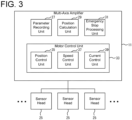
- FIG. 3 is a block diagram showing an example of the functional configuration of the control unit of the multi-axis amplifier 11, and the power supply unit is not shown.
- the multi-axis amplifier 11 has a parameter recording unit (an example of "a parameter memory") 27, a position calculation unit (an example of "position calculation circuitry") 29, an emergency stop processing unit (an example of "emergency stop processing circuitry”) 31, and a motor control unit 33.
- the motor control unit 33 controls the energization of each of the three sets of coils 17 to control a linear motor constituted by the three sets of coils 17 and the movable element 5.
- the motor control unit 33 has a position control unit 35, a speed control unit 37, and a current control unit 39.
- the position control unit 35 generates a speed command based on a position deviation between a position command from the linear controller 13 and a machine coordinate position (calculated by the position calculation unit 29) of the movable element 5 based on the detection data of the sensor head.
- the speed control unit 37 generates a torque command based on the speed deviation between the speed command generated by the position control unit 35 or the speed command from the linear controller 13 and the speed of the movable element 5 based on the detection data of the sensor head 25.
- the current control unit 39 converts the torque command generated by the speed control unit 37 into a current command, generates a voltage command based on the current command and the detection data of the current sensor that detects the current supplied to the coil 17, and generates a control signal (for example, a PWM signal or the like) based on the voltage command.
- the control signal is output to an inverter unit (not illustrated).
- the inverter unit converts DC power into AC power based on the control signal and supplies the AC power to the coil 17.
- the parameter recording unit 27 records an error correction value for correcting an error between a set value of an installation interval (an example of "respective intervals") of the sensor head 25 and a measured value obtained by measuring the installation interval in advance, and a first cumulative value accumulated from the sensor head 25 set at the origin (an example of "a reference position") as a parameter for each sensor head 25.
- the error correction value may be an error value obtained by subtracting the set value from the measured value, or may be a measured value itself in which the error value is incorporated.
- the first cumulative value may be a cumulative error value obtained by accumulating error values or a cumulative measurement value obtained by accumulating measurement values.
- the installation interval of the sensor head 25 may be measured, for example, by moving the measuring movable element 5 having a scale 23 longer than the installation interval along the stator 3. In this case, the difference between the detection data of the adjacent sensor heads becomes a measurement value of the installation interval.
- the parameter recording unit 27 records the second cumulative value accumulated from the sensor head 25 whose origin is set to the set value of the installation interval of the sensor head 25 as a separate parameter for each sensor head 25.
- the parameter recording unit 27 records the origin correction value, which is the detection data of the sensor head 25 that has detected the scale 23 of the movable element 5, as a parameter common to a plurality of sensor heads 25 disposed on the same stator 3, when the movable element 5 is located at a desired position as the origin.
- the parameter recording unit 27 may record the parameters (first cumulative value, second cumulative value, origin correction value) for the three sensor heads 25 connected to the multi-axis amplifier 11 to which the parameter recording unit 27 belongs, or may record the parameters for all the sensor heads 25 arranged in the common stator 3.
- a nonvolatile memory such as an EEPROM or a recording device such as a hard disk may be used.
- the parameter recording unit 27 may be provided outside the multi-axis amplifier 11, for example, in a linear controller 13, an operation controller 15, a sensor head 25, or other external recording devices and the like . In this case, the multi-axis amplifier 11 may obtain necessary information from a parameter recording unit 27 provided outside.
- a position calculation unit 29 calculates the machine coordinate position of a movable element 5 on the basis of detection data of a sensor head 25 which has detected a scale 23, a first cumulative value and a second cumulative value which are parameters set for the sensor head 25 which has detected the scale 23, and an origin correction value which is a parameter common to a plurality of sensor heads 25. Details of the calculation method will be described later.
- An emergency stop processing unit 31 determines whether or not two or more movable elements 5 exist within a predetermined interval of a stator 3 on the basis of the machine coordinate position of the movable element 5 calculated by a position calculation unit 29, and stop emergently all or a part of the two or more movable elements 5 (for example, the rear movable element 5) when it is determined that two or more movable elements 5 exist.
- the predetermined interval is a coil pitch of a pair of coils 17 including, for example, a U-phase coil 17U, a V-phase coil 17V, and a W-phase coil 17W.
- the multi-axis amplifier 11 performs energization control for each pair of coils 17 to control the position of the movable element 5.
- the processes in the parameter recording unit 27, the position calculation unit 29, the emergency stop processing unit 31, the motor control unit 33 and the like described above are not limited to examples of sharing of these processes.
- the processing may be performed by a smaller number of processing units (for example, one processing unit), or may be performed by further subdivided processing units.
- a portion for supplying electric power to the coil 17 for example, an inverter portion, a PWM control circuit or the like
- the CPU901 see FIG. 13 ) described later.
- each processing unit may be implemented by an actual device such as an ASIC, an FPGA, or other electric circuit.
- the functions of each processing section are not necessarily executed only by the multi-axis amplifier 11, and some or all of them may be executed by the linear controller 13 or the operation controller 15.
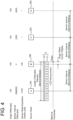
- the total length of the movable element 5 in the moving direction (the total length of the scale 23) is 30 mm
- the number of pulses generated when each of the sensor heads 25A to 25D detects the total length of the scale 23 is 3000 pulses (pls)
- the sensor head acquisition position (an example of detection data) by the sensor head 25B with respect to the scale 23 of the movable element 5 located at the origin becomes 100 pulses
- the origin offset (an example of origin correction value ) becomes 100 pulses.
- the origin offset is recorded as a parameter common to all the sensor heads 25 arranged in the common stator 3.
- the sensor interval offset (an example of the second cumulative value) obtained by accumulating the set value of the installation interval of each sensor head 25 from the sensor head 25B set at the origin is recorded as a separate parameter for each sensor head 25.
- the sensor interval offset is, for example, 0 pulses in the sensor head 25B, 2000 pulses in the sensor head 25C, 4000 pulses in the sensor head 25D, and 2998000 pulses in the sensor head 25A.
- FIG. 4 shows a case where the movable element 5 is located at the origin.
- the sensor head acquisition position by the sensor head 25B becomes 100 pulses
- the sensor head acquisition position by the sensor head 25A becomes 2100 pulses.
- the position calculation unit 29 calculates the machine coordinate position of the movable element 5 based on the following equation (1).
- Mechanical coordinate position pls of movable element sensor head acquisition position pls + sensor interval offset pls ⁇ origin offset pls
- the mechanical coordinate position of the movable element 5 is the origin position regardless of which detection data of the sensor heads 25A and 25B is used.
- the scale 23 is not detected by the sensor heads 25A and 25B.
- the sensor head acquisition position by the sensor head 25D becomes 100 pulses
- the sensor head acquisition position by the sensor head 25C becomes 2100 pulses.
- the machine coordinate position of the movable element 5 becomes 4000 pulses even when calculated using the sensor head acquisition position by the sensor head 25D, and becomes 4000 pulses even when calculated using the sensor head acquisition position by the sensor head 25C.
- FIG. 6 shows an example of a calculation method of the machine coordinate position of the movable element in the case where there is an error in the installation interval of each sensor head 25.
- an error value (an example of the error correction value ) obtained by subtracting the set value from the measured value obtained by measuring the installation interval between the sensor heads 25 in advance
- a sensor interval error correction cumulative value (an example of the first cumulative value) accumulated from the sensor head 25B set at the origin are recorded as separate parameters for each sensor head 25.
- the sensor interval error correction cumulative value is, for example, 0 pulses for the sensor head 25B, 300 pulses for the sensor head 25C, and 400 pulses for the sensor head 25D.
- the origin offset and sensor interval offset are the same as those shown in FIGS. 4 and 5 .
- the sensor head acquisition position by the sensor head 25D becomes 100 pulses
- the sensor head acquisition position by the sensor head 25C becomes 2200 pulses.
- the position calculation unit 29 calculates the machine coordinate position of the movable element 5 based on the following equation (2).
- Machine coordinate position pls of movable element sensor head acquisition position pls + sensor interval error correction cumulative value pls + sensor interval offset pls ⁇ origin offset pls
- the machine coordinate position of the movable element 5 becomes 4400 pulses even when calculated using the sensor head acquisition position by the sensor head 25D, and becomes 4400 pulses even when calculated using the sensor head acquisition position by the sensor head 25C.
- FIG. 7 shows another example of a calculation method of the machine coordinate position of the movable element in the case where there is an error in the installation interval of each sensor head 25.
- the measurement value of the installation interval of each sensor head 25 is similar to that shown in FIG. 6 .
- the sensor interval error correction offset (an example of the first cumulative value), which is obtained by accumulating the measurement value of the installation interval of each sensor head 25 from the sensor head 25B set at the origin, is recorded as a separate parameter for each sensor head 25.
- the sensor interval error corrected offset is, for example, 0 pulses in the sensor head 25B, 2300 pulses in the sensor head 25C, and 4400 pulses in the sensor head 25D.
- the sensor head acquisition position by the sensor head 25D becomes 100 pulses
- the sensor head acquisition position by the sensor head 25C becomes 2200 pulses.
- the position calculation unit 29 calculates the machine coordinate position of the movable element 5 based on the following equation (3).
- Mechanical coordinate position pls of movable element sensor head acquisition position pls + sensor interval error corrected offset pls ⁇ origin offset pls
- the machine coordinate position of the movable element 5 becomes 4400 pulses even when calculated using the sensor head acquisition position by the sensor head 25D, and becomes 4400 pulses even when calculated using the sensor head acquisition position by the sensor head 25C.
- each cumulative value is accumulated from the sensor head 25B set to the origin, but may be a value accumulated from the origin in the machine coordinates.
- the sensor interval offset (an example of the second cumulative value) may be 2999900 pulses for the sensor head 25B, 1900 pulses for the sensor head 25C, 3900 pulses for the sensor head 25D, or 2997900 pulses for the sensor head 25A.
- the sensor interval error correction cumulative value (an example of the first cumulative value ) shown in FIG. 6 may be -100 pulses in the sensor head 25B, 200 pulses in the sensor head 25C, and 300 pulses in the sensor head 25D.
- the sensor interval error corrected offset (an example of the first cumulative value ) shown in FIG. 7 may be - 100 pulses in the sensor head 25B, 2200 pulses in the sensor head 25C, and 4300 pulses in the sensor head 25D. In these cases, the origin offset is not necessary.
- FIG. 8 is a flowchart showing an example of a processing procedure executed by the multi-axis amplifier 11.
- step S10 the multi-axis amplifier 11 acquires parameters of each sensor head 25 from the parameter recording unit 27.
- the parameters of the sensor head 25 include a sensor interval offset, an origin offset, and a sensor interval error correction cumulative value .
- step S20 the multi-axis amplifier 11 determines whether or not the connected sensor head 25 has detected the scale 23. If the scale 23 is not detected (step S20 : NO), this step S20 is repeated until the scale 23 is detected. When the scale 23 is detected (step S20 : YES), the process proceeds to step S30.
- step S30 the multi-axis amplifier 11 acquires the detection data from the sensor head 25 that has detected the scale 23.
- the detection data includes the movable element ID and the sensor head acquisition position.
- step S40 the multi-axis amplifier 11 calculates the machine coordinate position of the movable element 5 by the position calculation unit 29 based on the sensor head acquisition position acquired in step S30 and the parameter acquired in step S10.
- steps S10 to S40 parameters such as cumulative data are acquired before the scale 23 is detected, and only sensor head acquisition position data is acquired when the scale 23 is detected, so that the machine coordinate position can be calculated quickly.
- step S50 the multi-axis amplifier 11 performs position control or speed control of the movable element 5 by energizing the coil 17 based on the position command received from the linear controller 13 and the machine coordinate position of the movable element 5 calculated in step S40 by the motor control unit 33.
- step S60 the multi-axis amplifier 11 determines whether or not the detection of the scale 23 by the sensor head 25 has been completed.
- step S60 : NO the process returns to step S30.
- the procedure of steps S30 to S50 is repeated until the detection of the scale 23 is completed.
- step S60 : YES the process returns to step S20.
- processing procedure is an example, and at least a part of the above-described procedure may be deleted or changed, or a procedure other than the above-described procedure may be added. Further, the order of at least a part of the procedure may be changed, or a plurality of procedures may be combined into a single procedure.
- FIG. 9 is a block diagram showing an example of the functional configuration of the linear controller 13.
- the linear controller 13 has a collision prevention processing unit (an example of "collision prevention processing circuitry”) 41.
- the collision prevention processing unit 41 acquires the machine coordinate position of a movable element 5 calculated by a position calculation unit 29 of a multi-axis amplifier 11, and monitors the distance between a plurality of movable elements 5 based on the machine coordinate position of the movable element 5 to prevent a collision.
- the collision prevention processing unit 41 includes a distance determination unit (an example of "distance determination circuitry") 43, an acceleration/deceleration control unit (an example of “acceleration/deceleration control circuitry”) 45, and a speed determination unit (an example of "speed determination circuitry”) 47.
- a distance determination unit 43 determines whether or not an actual distance between movable elements (an example of the distance between movable elements), which is the actual movable distance between a rear movable element 5R (an example of "a first movable element") located at the rear and a front movable element (5F) (an example of a second movable element) located at the front in the moving direction of a plurality of movable elements 5, is equal to or less than a predetermined traveling distance of the movable element (an example of a threshold value).
- the traveling distance between the movable elements is, for example, a sum of the set value of the distance between the movable elements, which is a value set in advance as the distance between the movable elements, and the deceleration distance of the rear movable element 5R, which is a braking distance required until the rear movable element 5R stops.
- the set value of the distance between movable elements varies according to the interval. For example, in front of the curve section, the set value of the distance between the movable elements may be increased more than in the straight section.
- the travel distance between the movable elements is not limited to the sum of the set value of the distance between the movable elements and the deceleration distance of the rear movable element 5R.
- the travel distance between the movable elements may be the sum of the set value of the distance between the movable elements and the relative distance required until the rear movable element 5R decelerates to the speed of the front movable element 5F.
- the travel distance between the movable elements may be the sum of the set value of the distance between the movable elements, the deceleration distance of the rear movable element, and the relative distance required for the rear movable element 5R to decelerate to the speed of the front movable element 5F.
- the acceleration/deceleration control unit 45 decelerates the speed of the rear movable element 5R so as to be substantially equal to the speed of the front movable element 5F when it is determined by the distance determination unit 43 that the actual distance between the movable elements is equal to or less than the distance between the movable elements during travel.
- the acceleration/deceleration control unit 45 executes additional deceleration on the basis of a difference value obtained by subtracting the actual distance between the movable elements from the distance between the movable elements during travel.
- the additional deceleration makes it possible to increase the actual distance between the movable elements, and an appropriate distance between the movable elements can be maintained by performing the additional deceleration until the actual distance between the movable elements is greater than the distance between the movable elements during travel.
- the difference value is an amount of representing how closely approached the distance between the rear movable element 5R and the front movable element 5F is and become shorter than the distance between the movable elements during travel.
- the additional deceleration is executed so that the smaller the actual distance between the movable elements after the approach (the larger the approach amount), the larger the deceleration amount.
- additional deceleration may be executed in proportion to the approaching distance, such as + 1% deceleration of the rear movable element 5R when the distance between the actual movable elements is 99 mm (when the approaching distance is 1 mm), + 10% deceleration of the rear movable element 5R when the distance between the actual movable elements is 90 mm (when the approaching distance is 10 mm), and + 90% deceleration of the rear movable element 5R when the distance between the actual movable elements is 10 mm (when the approaching distance is 90 mm).
- a speed determination unit 47 determines whether or not the speed of the front movable element 5F is greater than the command speed of the rear movable element 5R.
- the command speed of the rear movable element 5R is a command speed based on a speed profile based on a position command for the rear movable element 5R.
- the acceleration/deceleration control unit 45 controls the speed of the rear movable element 5R so as to follow the command speed when the speed determination unit 47 determines that the speed of the front movable element 5F is greater than the command speed of the rear movable element 5R.
- the processes in the collision prevention processing unit 41, the distance determination unit 43, the acceleration/deceleration control unit 45, the speed determination unit 47 and the like described above are not limited to examples of the sharing of these processes.
- the processing may be performed by a smaller number of processing units (for example, one processing unit), or may be performed by further subdivided processing units.
- the functions of each processing unit may be implemented by a program executed by the CPU901 (see FIG. 13 ) described later, or part or all of the functions may be implemented by an actual device such as an ASIC, an FPGA, or other electric circuits.
- the functions of each processing unit are not necessarily executed only by the linear controller 13, and some or all of them may be executed by the operation controller 15 or the multi-axis amplifier 11.
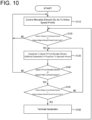
- FIG. 10 is a flowchart showing an example of a processing procedure executed by the linear controller 13.
- step 110 the linear controller 13 controls the position or speed of the movable element 5 so as to follow the speed profile based on the position command received from the operation controller 15.
- step 120 the linear controller 13 determines whether or not the actual distance between the movable element 5 (hereinafter referred to as "rear movable element 5R") to be processed and the front movable element 5F located in front of the movable element 5F is equal to or less than the distance between the movable elements during travel by the distance determination unit 43. If the actual distance between the movable elements is greater than the distance between the movable elements during travel (step S120 : NO), the process returns to step S110. When the actual distance between the movable elements is equal to or less than the distance between the movable elements during travel (step S120 : YES), the process proceeds to step S130.
- step S130 the linear controller 13 reduces the speed of the rear movable element 5R by the acceleration/deceleration control unit 45 so as to be substantially equal to the speed of the front movable element 5F. Further, when the speed of the rear movable element 5R is substantially equal to the speed of the front movable element 5F, the linear controller 13 executes an additional deceleration by the acceleration/deceleration control unit 45 in proportion to a difference value (approach amount) obtained by subtracting the actual distance between the movable elements from the distance between the movable elements during travel.
- step 140 the linear controller 13 determines whether or not the speed of the front movable element 5F is equal to or less than the command speed based on the speed profile of the rear movable element 5R by the speed determination unit 47.
- step S140 NO
- the process returns to the previous step S110 to control the position or speed of the rear movable element 5R so as to follow the speed profile.
- step S140 YES
- the process proceeds to step S150.
- step S150 the linear controller 13 determines whether or not the distance between the rear movable element 5R and the front movable element 5F between the actual movable elements 5 is greater than the distance between the traveling movable elements 5 by the distance 43.
- step S150 : NO the process returns to step S130 to continue the deceleration. If the actual distance between the movable elements is greater than the distance between the movable elements during travel (step S150 : YES), the process proceeds to step S160.
- step 160 the linear controller 13 terminates the deceleration with respect to the rear movable element 5R by the acceleration/deceleration control unit 45. Thereafter, the process returns to step 120.
- processing procedure is an example, and at least a part of the above-described procedure may be deleted or changed, or a procedure other than the above-described procedure may be added. Further, the order of at least a part of the procedure may be changed, or a plurality of procedures may be combined into a single procedure.
- the rear movable element 5R (an example of a first movable element) to be processed and the front movable element 5F (an example of a second movable element) located in front of the rear movable element 5R are traveling with the actual distance between the movable elements being 300 mm, the distance between the movable elements during travel being 262.5 mm, the speed of the rear movable element 5R being 1500 mm/sec, the speed of the front movable element 5F being 1000 mm/sec, and acceleration/deceleration being 10m/S 2 .
- the rear movable element 5R is controlled to follow the speed profile (step S110 in FIG. 10 ).
- step S120 in FIG. 10 YES
- step S130 in FIG. 10 the speed of the rear movable element 5R is decelerated so as to be substantially equal to the speed of the front movable element 5F.
- the rear movable element 5R approaches the front movable element 5F, and the actual distance between the movable elements becomes shorter.
- the speed of the rear movable element 5R is decelerated to 1250 mm/sec, and the distance between the actual movable elements 5 is 228.125 mm.
- the speed of the rear movable element 5R is decelerated until the speed of the front movable element 5F is substantially equal to the speed of the rear movable element 5R.
- the speed of the rear movable element 5R is reduced to 1000 mm/sec, which is the same as that of the front movable element 5F, and the actual distance between the movable elements is 200 mm. Further, an additional deceleration is started for the rear movable element 5R. In the example shown in FIG.
- the speed of the rear movable element 5R is decelerated to 762 mm/sec by the additional deceleration, and the actual distance between the movable elements is 262.5 mm.
- the command speed based on the speed profile of the rear movable element 5R is smaller than the speed 1000 mm/sec of the front movable element 5F (step S140 in FIG. 10 : NO)
- the rear movable element 5R is controlled so as to follow the speed profile (step S110 in FIG. 10 ).
- step S150 in FIG. 10 YES
- step S160 in FIG. 10 the deceleration of the rear movable element 5R is terminated
- FIGS. 12A-12D show specific examples of the operation of the movable element 5 when the set value of the distance between the movable elements fluctuates.
- the rear movable element 5R an example of the first movable element 5
- the front movable element 5F an example of the second movable element 5
- the rear movable element 5R an example of the first movable element 5
- the front movable element 5F an example of the second movable element 5
- step S120 in FIG. 10 NO
- the rear movable element 5R is controlled to follow the speed profile (step S 110 in FIG. 10 ).
- the set value of the distance between the movable elements gradually changes in front of the curve section.
- the set value of the distance between the movable elements gradually increases in the range of 150 mm to 300 mm, and accordingly, the distance between the movable elements during travel changes to 350 mm.
- deceleration is started with respect to the rear movable element 5R (step S130 in FIG. 10 ).
- the actual distance between the movable elements gradually increases from 250 mm.
- the actual distance between the movable elements becomes larger than 350 mm due to the deceleration with respect to the rear movable element 5R (step S150 in FIG. 10 : YES), and the deceleration with respect to the rear movable element 5R is terminated (step S160 in FIG. 10 ).
- the rear movable element 5R and the front movable element 5F enter the curved section while maintaining the distance (350 mm) between the movable elements during travel at the same speed of 1000 mm/sec.
- the actual distance between the movable elements can be made larger than that in the straight section to allow the movable elements 5 to travel, and collision between the movable elements can be prevented more reliably.
- the set value of the distance between the movable elements changes.
- the set value of the distance between the movable elements returns to the original value of 150 mm, for example, and accordingly, the distance between the movable elements during traveling returns to the original value of 200 mm.
- the rear movable element 5R is controlled to follow the speed profile (step S110 in FIG. 10 ).
- the linear transport system 1 of the present embodiment includes a stator 3 having a plurality of coils 17, a plurality of movable elements 5 having magnets 21 and moving along the stator 3 to convey a workpiece, a scale 23 provided on the movable elements 5, a plurality of sensor heads 25 arranged along the stator 3 at a predetermined installation interval to detect the scale 23, a parameter recording unit 27 which records a sensor interval error correction cumulative value or a sensor interval error-corrected offset accumulated from the sensor head 25 whose origin is set to an error value for correcting an error between the set value of the installation interval and a measured value, or a measured value, as a parameter for each sensor head 25, and a position calculation unit 29 which calculates a machine coordinate position of the movable elements 5 based on the detection data of the sensor head 25 having detected the scale 23 and the accumulated sensor interval error correction value or the sensor interval error-corrected offset set in the sensor head 25 having detected the scale 23.
- the movable element 5 moves along the stator 3 to convey the workpiece.
- a plurality of sensor heads 25 arranged along the stator 3 at predetermined intervals detect a scale 23 provided on the movable element 5.
- the parameter recording unit 27 an error value for correcting an error between a set value of an installation interval between sensor heads 25 and a previously measured value, or a sensor interval error correction cumulative value or a sensor interval error correction offset accumulated from the sensor head 25 with the measured value set as an origin, are recorded as separate parameters for each sensor head 25.
- the position calculation unit 29 calculates the machine coordinate position of the movable element 5 on the basis of the detection data of the sensor head 25 which has detected the scale 23 and the sensor interval error correction cumulative value or the sensor interval error correction offset set for the sensor head 25 which has detected the scale 23. In this way, the mechanical coordinate position of the movable element 5 can be calculated using only the detection data of the sensor head 25 that has detected the scale 23 and the parameters set for the sensor head 25. Since the processing for reading out the parameters of the other sensor head 25 or the like is unnecessary, the processing speed is increased, and the machine coordinate position of the movable element 5 can be calculated quickly. Therefore, the reliability of the linear transport system 1 can be improved.
- the sensor heads 25 other than the replaced sensor head 25 do not change because the parameter related to the error is a cumulative value. Therefore, only the parameters relating to the replaced sensor head 25 may be reset, and the installation interval measurement work and parameter setting work at the time of sensor replacement can be facilitated.
- the sensor interval error correction cumulative value may be a value accumulated from the sensor head 25 whose origin is the error value between the set value of the installation interval and the measured value
- the parameter recording unit 27 may record the sensor interval offset accumulated from the sensor head 25 whose origin is the set value of the installation interval as a separate parameter for each sensor head 25, and the position calculation unit 29 may calculate the machine coordinate position of the movable element 5 based on the detection data of the sensor head 25 which detected the scale 23, and the sensor interval error correction cumulative value and the sensor interval offset set in the sensor head 25 which detected the scale 23.
- the cumulative value of the set value of the installation interval and the cumulative value of the error value of the installation interval are recorded as separate parameters for each sensor head 25.
- the magnitude of the accumulated error value in each sensor head 25 becomes clear, and the error value can be easily controlled.
- the parameter recording unit 27 may record the origin offset, which is the detection data of the sensor head 25 that detected the scale 23 of the movable element 5, as a parameter common to a plurality of sensor heads 25 when the movable element 5 is located at a position to be the origin, and the position calculation unit 29 may calculate the machine coordinate position of the movable element 5 based on the detection data of the sensor head 25 that detected the scale 23, the accumulated sensor interval error correction value set for the sensor head 25 that detected the scale 23, and the origin offset.
- the origin offset is the detection data of the sensor head 25 that detected the scale 23 of the movable element 5
- the position calculation unit 29 may calculate the machine coordinate position of the movable element 5 based on the detection data of the sensor head 25 that detected the scale 23, the accumulated sensor interval error correction value set for the sensor head 25 that detected the scale 23, and the origin offset.
- an arbitrary position on the stator 3 can be set as the origin, and the machine coordinate position of the movable element 5 can be calculated with the origin as a reference. Therefore, the degree of freedom in setting the machine coordinates is increased, and the convenience of the user can be improved. Further, since the origin offset can be set as a parameter common to each sensor head 25, the parameter setting operation is facilitated.
- the linear transport system 1 may further comprise a multi-axis amplifier 11 for controlling the energization of a coil 17 in a part section of a stator 3, and a linear controller 13 connected to the multi-axis amplifiers 11 for managing the machine coordinate positions of the plurality of movable elements 5, in which case the linear controller 13 may comprise a collision prevention processing unit 41 for preventing a collision by monitoring the distance between the plurality of movable elements 5 on the basis of the machine coordinate position of the movable element 5 calculated by the position calculation unit 29 of the multi-axis amplifier 11, and the multi-axis amplifier 11 may comprise an emergency stop processing unit 31 for determining whether two or more movable elements 5 are present in a predetermined section of the stator 3 on the basis of the machine coordinate position of the movable element 5 calculated by the position calculation unit 29 and for urgently stopping the movable element 5 when it is determined that two or more movable elements 5 are present.
- the linear controller 13 may comprise a collision prevention processing unit 41 for preventing a collision by monitoring the distance between
- the linear transport system 1 can be provided with a two stage collision prevention function by two control methods, and a linear transport system 1 having a high collision prevention function can be realized. Further, by adopting a system in which the machine coordinate position of the movable element 5 is calculated by the multi-axis amplifier 11 having a processing speed higher than that of the linear controller 13, and the upper linear controller 13 performs collision prevention by utilizing the position of the movable element 5, collision prevention processing for the entire movable element 5 using the position of the movable element 5 with high accuracy becomes possible, and reliability can be improved.
- the collision prevention processing unit 41 may have a distance determination unit 43 for determining whether or not the actual distance between the rear movable element 5R positioned rearward in the moving direction of the plurality of movable elements 5 and the front movable element 5F positioned forward in the moving direction of the plurality of movable elements 5 is equal to or less than the distance between the movable elements 5 during travel, and an acceleration/deceleration control unit 45 for decelerating the speed of the rear movable element 5R so as to be equal to the speed of the front movable element 5F when the distance between the real movable elements 5 is determined by the distance determination unit 43 to be equal to or less than the distance between the movable elements 5 during travel.
- a distance determination unit 43 for determining whether or not the actual distance between the rear movable element 5R positioned rearward in the moving direction of the plurality of movable elements 5 and the front movable element 5F positioned forward in the moving direction of the plurality of movable elements 5 is equal to or less than the distance
- the linear transport system 1 can be realized which can prevent the collision of each movable element 5 while suppressing the increase in the tact time of the workpiece conveying.
- the travel distance between the movable elements 5 may be the sum of the set value of the distance between the movable elements 5 set in advance as the distance between the movable elements 5 and the deceleration distance of the rear movable element 5R required until the rear movable element 5R stops.
- the distance between the movable elements during travel can be set to the sum of the set value of the distance between the movable elements and the braking distance of the rear movable element 5R.
- the distance between the actual movable elements becomes within a predetermined distance, and even when the rear movable element 5R is stopped, the distance between the actual movable elements can be maintained at a set value of minutes. Therefore, the effectiveness of the collision prevention function can be enhanced.
- the acceleration/deceleration control unit 45 may perform additional deceleration on the basis of the difference value obtained by subtracting the distance between the real movable elements from the distance between the traveling movable elements.
- the collision prevention processing unit 41 may have a speed determination unit 47 for determining whether or not the speed of the front movable element 5F is greater than the command speed of the rear movable element 5R when the speed of the rear movable element 5R is decelerated to be equal to the speed of the front movable element 5F, and in this case, the acceleration/deceleration control unit 45 may control the speed of the rear movable element 5R so as to follow the command speed when the speed determination unit 47 determines that the speed of the front movable element 5F is greater than the command speed of the rear movable element 5R.
- FIG. 13 a description will be given of a hardware configuration example of the multi-axis amplifier 11 which realizes processing by the parameter recording unit 27, the position calculation unit 29, the emergency stop processing unit 31, the motor control unit 33 and the like implemented by the program executed by the CPU901 described above.
- a configuration relating to a function of supplying electric power to the coil 17 of the multi-axis amplifier 11 is omitted.
- the hardware configuration of the linear controller 13 for realizing the processing by the collision prevention processing unit 41, the distance determination unit 43, the acceleration/deceleration control unit 45, the speed determination unit 47, and the like may be similarly configured.
- the multi-axis amplifier 11 (or linear controller 13) includes, for example, a CPU901, a ROM903, a RAM905, a dedicated integrated circuit 907 constructed for a specific application such as an ASIC or an FPGA, an input device 913, an output device 915, a recording device 917, a drive 919, a connection port 921, and a communication device 923. These configurations are connected so as to be able to transmit signals to each other via a bus 909 and an input/output interface 911.
- the program can be recorded in, for example, a ROM903, a RAM905, a recording device 917 using a hard disk, or the like.
- the program can also be recorded temporarily or non-temporarily (permanently) on a removable recording medium 925 such as a magnetic disk such as a flexible disk, an optical disk such as a CD, MO disk or DVD, or a semiconductor memory.
- a recording medium 925 can be provided as so-called package software.
- the program recorded on the recording medium 925 may be read by the drive 919 and recorded on the recording device 917 via the input/output interface 911, the bus 909, or the like.
- the program may be recorded in a download site, another computer, another recording device, or the like (not shown).
- the program is transferred via a network NW such as a LAN or the Internet, and the communication device 923 receives the program.
- the program received by the communication device 923 may be recorded in the recording device 917 via the input/output interface 911, the bus 909, or the like.
- the program may also be recorded in an appropriate external connection device 927, for example.
- the program may be transferred via an appropriate connection port 921 and recorded in the recording device 917 via an input/output interface 911, a bus 909, or the like.
- the CPU901 executes various processes according to the program recorded in the recording device 917, thereby realizing processes by the parameter recording unit 27, the position calculation unit 29, the emergency stop processing unit 31, the motor control unit 33, and the like.
- the CPU901 may directly read a program from the recording device 917 and execute the program, or may temporarily load the program into the RAM905 and execute the program.
- the CPU901 receives a program via, for example, the communication device 923, the drive 919, or the connection port 921, it may directly execute the received program without recording it in the recording device 917.
- the CPU901 may perform various processes based on signals or information input from an input device 913 such as a mouse, keyboard, microphone (not shown), for example, as needed.
- an input device 913 such as a mouse, keyboard, microphone (not shown), for example, as needed.
- the CPU901 may output the result of executing the above-described processing from an output device 915 such as a display device or an audio output device, and the CPU901 may transmit the processing result via the communication device 923 or the connection port 921 if necessary, and may record the processing result in the recording device 917 or the recording medium 925.
- an output device 915 such as a display device or an audio output device
- a threshold value see the flow chart of FIG. 8 and FIG. 10
- a reference value, or the like is described as a predetermined criterion value or a delimiting value, "same”, “equal”, “different” and the like for these values are different from those described above and have strict meanings.
- a component suffixed with a term such as “member” , “portion” , “part” , “element” , “body” , and “structure” is intended to mean that there is a single such component or a plurality of such components.
- ordinal terms such as “first” and “second” are merely used for distinguishing purposes and there is no other intention (such as to connote a particular order) in using ordinal terms.
- first element does not connote the existence of “second element” ; otherwise, the mere use of “second element” does not connote the existence of "first element”
- approximating language such as “approximately” , “about” , and “substantially” may be applied to modify any quantitative representation that could permissibly vary without a significant change in the final result obtained. All of the quantitative representations recited in the present application shall be construed to be modified by approximating language such as “approximately” , “about” , and “substantially”
Landscapes
- Engineering & Computer Science (AREA)
- Human Computer Interaction (AREA)
- Manufacturing & Machinery (AREA)
- Physics & Mathematics (AREA)
- General Physics & Mathematics (AREA)
- Automation & Control Theory (AREA)
- Control Of Linear Motors (AREA)
- Control Of Vehicles With Linear Motors And Vehicles That Are Magnetically Levitated (AREA)
- Non-Mechanical Conveyors (AREA)
- Linear Motors (AREA)
Applications Claiming Priority (1)
| Application Number | Priority Date | Filing Date | Title |
|---|---|---|---|
| JP2021123752A JP7316554B2 (ja) | 2021-07-28 | 2021-07-28 | リニア搬送システム、リニア搬送システムの制御方法 |
Publications (2)
| Publication Number | Publication Date |
|---|---|
| EP4194977A2 true EP4194977A2 (de) | 2023-06-14 |
| EP4194977A3 EP4194977A3 (de) | 2023-08-23 |
Family
ID=82656743
Family Applications (1)
| Application Number | Title | Priority Date | Filing Date |
|---|---|---|---|
| EP22179584.2A Withdrawn EP4194977A3 (de) | 2021-07-28 | 2022-06-17 | Lineares transportsystem und verfahren zur steuerung eines linearen transportsystems |
Country Status (4)
| Country | Link |
|---|---|
| US (1) | US20230038090A1 (de) |
| EP (1) | EP4194977A3 (de) |
| JP (1) | JP7316554B2 (de) |
| CN (1) | CN115676336A (de) |
Families Citing this family (9)
| Publication number | Priority date | Publication date | Assignee | Title |
|---|---|---|---|---|
| CN115097851B (zh) * | 2022-06-30 | 2025-04-22 | 瑞声光电科技(常州)有限公司 | 直驱传输系统的控制方法及相关设备 |
| KR102888883B1 (ko) * | 2023-03-23 | 2025-11-20 | 미쓰비시덴키 가부시키가이샤 | 리니어 트랙 제어 장치 및 리니어 트랙 시스템 |
| WO2024214271A1 (ja) * | 2023-04-14 | 2024-10-17 | 三菱電機株式会社 | 駆動制御装置とリニアモータシステムおよび駆動制御方法 |
| CN116176634B (zh) * | 2023-04-27 | 2023-07-14 | 成都西交华创科技有限公司 | 一种轨道板式运载系统及运载方法 |
| CN116466728B (zh) * | 2023-06-20 | 2023-09-15 | 潍柴动力股份有限公司 | 上下料平台控制方法、装置及平台 |
| CN118894375B (zh) * | 2024-07-25 | 2025-08-26 | 果栗智造(上海)技术股份有限公司 | 一种动子防碰撞控制方法、装置及磁驱电机输送系统 |
| CN119182338B (zh) * | 2024-09-06 | 2025-07-18 | 果栗智造(上海)技术股份有限公司 | 与线性电机设备相关的方法、装置、存储介质及电子设备 |
| CN118894359B (zh) * | 2024-10-08 | 2024-12-27 | 深圳精智达技术股份有限公司 | 一种同向双动子防撞的控制方法、系统及装置 |
| CN119429705B (zh) * | 2024-11-08 | 2025-06-17 | 上海纵苇科技有限公司 | 磁驱输送系统的动子控制方法及相关设备 |
Citations (1)
| Publication number | Priority date | Publication date | Assignee | Title |
|---|---|---|---|---|
| WO2018055772A1 (ja) | 2016-09-26 | 2018-03-29 | ヤマハ発動機株式会社 | リニアコンベア装置及びその駆動制御方法 |
Family Cites Families (5)
| Publication number | Priority date | Publication date | Assignee | Title |
|---|---|---|---|---|
| EP2634913A4 (de) * | 2010-10-26 | 2017-02-22 | Murata Machinery, Ltd. | Verteiltes linearmotorsystem |
| JP5912426B2 (ja) * | 2011-11-07 | 2016-04-27 | ヤマハ発動機株式会社 | リニアコンベア |
| US9958852B2 (en) * | 2016-01-25 | 2018-05-01 | Rockwell Automation Technologies, Inc. | Multi-mover linear motor controller providing shared coordination subsystem |
| CN108328249B (zh) * | 2017-07-06 | 2019-10-25 | 上海果栗自动化科技有限公司 | 一种线性传输系统 |
| US10889449B2 (en) * | 2017-09-25 | 2021-01-12 | Canon Kabushiki Kaisha | Transport system and manufacturing method of article |
-
2021
- 2021-07-28 JP JP2021123752A patent/JP7316554B2/ja active Active
-
2022
- 2022-06-15 CN CN202210674055.5A patent/CN115676336A/zh active Pending
- 2022-06-17 EP EP22179584.2A patent/EP4194977A3/de not_active Withdrawn
- 2022-06-30 US US17/853,921 patent/US20230038090A1/en not_active Abandoned
Patent Citations (1)
| Publication number | Priority date | Publication date | Assignee | Title |
|---|---|---|---|---|
| WO2018055772A1 (ja) | 2016-09-26 | 2018-03-29 | ヤマハ発動機株式会社 | リニアコンベア装置及びその駆動制御方法 |
Also Published As
| Publication number | Publication date |
|---|---|
| JP2023019218A (ja) | 2023-02-09 |
| JP7316554B2 (ja) | 2023-07-28 |
| EP4194977A3 (de) | 2023-08-23 |
| CN115676336A (zh) | 2023-02-03 |
| US20230038090A1 (en) | 2023-02-09 |
Similar Documents
| Publication | Publication Date | Title |
|---|---|---|
| EP4194977A2 (de) | Lineares transportsystem und verfahren zur steuerung eines linearen transportsystems | |
| US8796959B2 (en) | Discontinuous linear motor system | |
| CN107415768B (zh) | 线性同步电机推进系统的通用控制 | |
| CN106444762B (zh) | 自动引导运输车agv及运动控制方法和装置 | |
| JP4468224B2 (ja) | エレベータの位置検出システム及び方法 | |
| JP4074999B2 (ja) | 搬送台車システム | |
| EP1619100A2 (de) | System mit Laufkatze | |
| US12041872B2 (en) | Autonomous work machine, autonomous work system, method of controlling autonomous work machine, and storage medium | |
| US9335361B2 (en) | Method and apparatus for monitoring a multi-phase electrical system on a vehicle | |
| CN109581970A (zh) | 参数决定辅助装置 | |
| CN119486955B (zh) | 输送系统 | |
| CN115032977A (zh) | 控制系统 | |
| US20070016341A1 (en) | Traveling vehicle system and stop control method for traveling vehicle | |
| CN105320075A (zh) | 具有重叠控制的速度控制功能的数值控制装置 | |
| EP2439773A1 (de) | Beförderungssystem mit einem endlosantriebsmedium, verfahren zum identifizierens eines trägers dafür und träger | |
| CN110647109A (zh) | 数值控制装置 | |
| JP2002190695A (ja) | Xy移動装置及びxy移動装置を用いた電子部品装着装置 | |
| US8560197B2 (en) | Moving vehicle system and in-position determination method for moving vehicle | |
| TWI697198B (zh) | 移動體、及移動體系統 | |
| US9768721B2 (en) | Mobile body and mobile body system | |
| CN116534731A (zh) | 一种多台共轨无人起重机的防撞控制方法及系统 | |
| JP2020196369A (ja) | 列車制御システム | |
| CN117519191B (zh) | 多车跟行调度方法、装置和存储介质 | |
| CN114701521A (zh) | 自动驾驶方法、装置、自动驾驶车辆和电子设备 | |
| CN117308775B (zh) | 一种用于链条提升机构定位和静止检测方法和系统 |
Legal Events
| Date | Code | Title | Description |
|---|---|---|---|
| PUAI | Public reference made under article 153(3) epc to a published international application that has entered the european phase |
Free format text: ORIGINAL CODE: 0009012 |
|
| STAA | Information on the status of an ep patent application or granted ep patent |
Free format text: STATUS: THE APPLICATION HAS BEEN PUBLISHED |
|
| AK | Designated contracting states |
Kind code of ref document: A2 Designated state(s): AL AT BE BG CH CY CZ DE DK EE ES FI FR GB GR HR HU IE IS IT LI LT LU LV MC MK MT NL NO PL PT RO RS SE SI SK SM TR |
|
| PUAL | Search report despatched |
Free format text: ORIGINAL CODE: 0009013 |
|
| AK | Designated contracting states |
Kind code of ref document: A3 Designated state(s): AL AT BE BG CH CY CZ DE DK EE ES FI FR GB GR HR HU IE IS IT LI LT LU LV MC MK MT NL NO PL PT RO RS SE SI SK SM TR |
|
| RIC1 | Information provided on ipc code assigned before grant |
Ipc: B65G 54/02 20060101ALN20230720BHEP Ipc: G05B 19/416 20060101ALI20230720BHEP Ipc: G05B 19/19 20060101ALI20230720BHEP Ipc: G05B 19/418 20060101AFI20230720BHEP |
|
| STAA | Information on the status of an ep patent application or granted ep patent |
Free format text: STATUS: REQUEST FOR EXAMINATION WAS MADE |
|
| 17P | Request for examination filed |
Effective date: 20240216 |
|
| RBV | Designated contracting states (corrected) |
Designated state(s): AL AT BE BG CH CY CZ DE DK EE ES FI FR GB GR HR HU IE IS IT LI LT LU LV MC MK MT NL NO PL PT RO RS SE SI SK SM TR |
|
| GRAP | Despatch of communication of intention to grant a patent |
Free format text: ORIGINAL CODE: EPIDOSNIGR1 |
|
| STAA | Information on the status of an ep patent application or granted ep patent |
Free format text: STATUS: GRANT OF PATENT IS INTENDED |
|
| RIC1 | Information provided on ipc code assigned before grant |
Ipc: B65G 54/02 20060101ALN20250519BHEP Ipc: G05B 19/416 20060101ALI20250519BHEP Ipc: G05B 19/19 20060101ALI20250519BHEP Ipc: G05B 19/418 20060101AFI20250519BHEP |
|
| INTG | Intention to grant announced |
Effective date: 20250605 |
|
| STAA | Information on the status of an ep patent application or granted ep patent |
Free format text: STATUS: THE APPLICATION IS DEEMED TO BE WITHDRAWN |
|
| 18D | Application deemed to be withdrawn |
Effective date: 20251007 |