EP4194792B1 - Additively manufactured heat exchanger layer - Google Patents
Additively manufactured heat exchanger layer Download PDFInfo
- Publication number
- EP4194792B1 EP4194792B1 EP21461632.8A EP21461632A EP4194792B1 EP 4194792 B1 EP4194792 B1 EP 4194792B1 EP 21461632 A EP21461632 A EP 21461632A EP 4194792 B1 EP4194792 B1 EP 4194792B1
- Authority
- EP
- European Patent Office
- Prior art keywords
- fins
- heat exchanger
- medium
- cold
- hot
- Prior art date
- Legal status (The legal status is an assumption and is not a legal conclusion. Google has not performed a legal analysis and makes no representation as to the accuracy of the status listed.)
- Active
Links
Images
Classifications
-
- B—PERFORMING OPERATIONS; TRANSPORTING
- B33—ADDITIVE MANUFACTURING TECHNOLOGY
- B33Y—ADDITIVE MANUFACTURING, i.e. MANUFACTURING OF THREE-DIMENSIONAL [3D] OBJECTS BY ADDITIVE DEPOSITION, ADDITIVE AGGLOMERATION OR ADDITIVE LAYERING, e.g. BY 3D PRINTING, STEREOLITHOGRAPHY OR SELECTIVE LASER SINTERING
- B33Y80/00—Products made by additive manufacturing
-
- F—MECHANICAL ENGINEERING; LIGHTING; HEATING; WEAPONS; BLASTING
- F28—HEAT EXCHANGE IN GENERAL
- F28F—DETAILS OF HEAT-EXCHANGE AND HEAT-TRANSFER APPARATUS, OF GENERAL APPLICATION
- F28F3/00—Plate-like or laminated elements; Assemblies of plate-like or laminated elements
- F28F3/08—Elements constructed for building-up into stacks, e.g. capable of being taken apart for cleaning
-
- F—MECHANICAL ENGINEERING; LIGHTING; HEATING; WEAPONS; BLASTING
- F28—HEAT EXCHANGE IN GENERAL
- F28D—HEAT-EXCHANGE APPARATUS, NOT PROVIDED FOR IN ANOTHER SUBCLASS, IN WHICH THE HEAT-EXCHANGE MEDIA DO NOT COME INTO DIRECT CONTACT
- F28D9/00—Heat-exchange apparatus having stationary plate-like or laminated conduit assemblies for both heat-exchange media, the media being in contact with different sides of a conduit wall
- F28D9/0062—Heat-exchange apparatus having stationary plate-like or laminated conduit assemblies for both heat-exchange media, the media being in contact with different sides of a conduit wall the conduits for one heat-exchange medium being formed by spaced plates with inserted elements
- F28D9/0068—Heat-exchange apparatus having stationary plate-like or laminated conduit assemblies for both heat-exchange media, the media being in contact with different sides of a conduit wall the conduits for one heat-exchange medium being formed by spaced plates with inserted elements with means for changing flow direction of one heat exchange medium, e.g. using deflecting zones
-
- F—MECHANICAL ENGINEERING; LIGHTING; HEATING; WEAPONS; BLASTING
- F28—HEAT EXCHANGE IN GENERAL
- F28F—DETAILS OF HEAT-EXCHANGE AND HEAT-TRANSFER APPARATUS, OF GENERAL APPLICATION
- F28F3/00—Plate-like or laminated elements; Assemblies of plate-like or laminated elements
- F28F3/02—Elements or assemblies thereof with means for increasing heat-transfer area, e.g. with fins, with recesses, with corrugations
- F28F3/04—Elements or assemblies thereof with means for increasing heat-transfer area, e.g. with fins, with recesses, with corrugations the means being integral with the element
- F28F3/048—Elements or assemblies thereof with means for increasing heat-transfer area, e.g. with fins, with recesses, with corrugations the means being integral with the element in the form of ribs integral with the element or local variations in thickness of the element, e.g. grooves, microchannels
-
- F—MECHANICAL ENGINEERING; LIGHTING; HEATING; WEAPONS; BLASTING
- F28—HEAT EXCHANGE IN GENERAL
- F28F—DETAILS OF HEAT-EXCHANGE AND HEAT-TRANSFER APPARATUS, OF GENERAL APPLICATION
- F28F7/00—Elements not covered by group F28F1/00, F28F3/00 or F28F5/00
- F28F7/02—Blocks traversed by passages for heat-exchange media
-
- B—PERFORMING OPERATIONS; TRANSPORTING
- B64—AIRCRAFT; AVIATION; COSMONAUTICS
- B64D—EQUIPMENT FOR FITTING IN OR TO AIRCRAFT; FLIGHT SUITS; PARACHUTES; ARRANGEMENT OR MOUNTING OF POWER PLANTS OR PROPULSION TRANSMISSIONS IN AIRCRAFT
- B64D13/00—Arrangements or adaptations of air-treatment apparatus for aircraft crew or passengers, or freight space
- B64D13/06—Arrangements or adaptations of air-treatment apparatus for aircraft crew or passengers, or freight space the air being conditioned
- B64D13/08—Arrangements or adaptations of air-treatment apparatus for aircraft crew or passengers, or freight space the air being conditioned the air being heated or cooled
-
- F—MECHANICAL ENGINEERING; LIGHTING; HEATING; WEAPONS; BLASTING
- F05—INDEXING SCHEMES RELATING TO ENGINES OR PUMPS IN VARIOUS SUBCLASSES OF CLASSES F01-F04
- F05D—INDEXING SCHEME FOR ASPECTS RELATING TO NON-POSITIVE-DISPLACEMENT MACHINES OR ENGINES, GAS-TURBINES OR JET-PROPULSION PLANTS
- F05D2260/00—Function
- F05D2260/20—Heat transfer, e.g. cooling
- F05D2260/213—Heat transfer, e.g. cooling by the provision of a heat exchanger within the cooling circuit
-
- F—MECHANICAL ENGINEERING; LIGHTING; HEATING; WEAPONS; BLASTING
- F28—HEAT EXCHANGE IN GENERAL
- F28D—HEAT-EXCHANGE APPARATUS, NOT PROVIDED FOR IN ANOTHER SUBCLASS, IN WHICH THE HEAT-EXCHANGE MEDIA DO NOT COME INTO DIRECT CONTACT
- F28D21/00—Heat-exchange apparatus not covered by any of the groups F28D1/00 - F28D20/00
- F28D2021/0019—Other heat exchangers for particular applications; Heat exchange systems not otherwise provided for
- F28D2021/0021—Other heat exchangers for particular applications; Heat exchange systems not otherwise provided for for aircrafts or cosmonautics
-
- F—MECHANICAL ENGINEERING; LIGHTING; HEATING; WEAPONS; BLASTING
- F28—HEAT EXCHANGE IN GENERAL
- F28F—DETAILS OF HEAT-EXCHANGE AND HEAT-TRANSFER APPARATUS, OF GENERAL APPLICATION
- F28F2215/00—Fins
-
- F—MECHANICAL ENGINEERING; LIGHTING; HEATING; WEAPONS; BLASTING
- F28—HEAT EXCHANGE IN GENERAL
- F28F—DETAILS OF HEAT-EXCHANGE AND HEAT-TRANSFER APPARATUS, OF GENERAL APPLICATION
- F28F2225/00—Reinforcing means
- F28F2225/06—Reinforcing means for fins
-
- F—MECHANICAL ENGINEERING; LIGHTING; HEATING; WEAPONS; BLASTING
- F28—HEAT EXCHANGE IN GENERAL
- F28F—DETAILS OF HEAT-EXCHANGE AND HEAT-TRANSFER APPARATUS, OF GENERAL APPLICATION
- F28F2250/00—Arrangements for modifying the flow of the heat exchange media, e.g. flow guiding means; Particular flow patterns
- F28F2250/02—Streamline-shaped elements
Definitions
- a heat transfer layer according to the preamble of claim 1 is known from document US 2016/230595 A1 .
- Heat exchangers are used to transfer heat between mediums to provide warming or cooling.
- Heat exchangers are used, for example, in vehicles and aircraft for e.g. air conditioning or environmental control systems (ECS) and/or for providing cooling to electronics and electrical rack mounted equipment, or to heat or cool another medium, for example.
- ECS air conditioning or environmental control systems
- Such heat exchangers commonly comprise a flow path/paths for hot and cold mediums. Heath transfer takes place between path surfaces.
- Such heat exchangers are well-known and will not be described in detail herein.
- the warm medium may be bleed air from the engine and the cold medium may be ambient or so-called RAM air.
- the RAM air is drawn in from outside the aircraft into the heat exchanger.
- the cold RAM air exchanges heat with the hot bleed air in the heat exchanger and heated air at a temperature deemed comfortable for the passengers is ducted into the cabin.
- Heat exchangers typically have very thin heat exchange structures (sometimes known as fins) which define channels for the flow of hot air.
- the flow direction of the hot medium may be varied in relation to the heat exchanger structure and in relation to the cold medium, according to the application.
- the fins are generally very thin, to ensure good heat exchange properties.
- the use of such thin fins can result in the fins becoming damaged.
- Sources of damage could be high inlet pressure, hailstones, and different types of debris or pollution.
- the impact of hailstones on the exposed parts can be very high. Damage can result to the heat exchange fins requiring replacement of the entire heat exchanger.
- a problem with such additional components is that they can cause flow distortion at the medium inlet. Having a thicker part at the inlet can create large temperature gradients through the heat exchanger layer. Further, additional parts add to the cost and complexity of manufacturing or design.
- a heat transfer layer of a heat exchanger having an inlet side, IN, where a medium enters the layer and an outlet side, OUT, where the medium exits the layer, and a plurality of additively manufactured fins defining a plurality of flow channels for the medium from the inlet side to the outlet side, each fin having a leading edge adjacent the inlet side and a trailing edge adjacent the outlet side, and wherein the leading edge of a subset of the fins is thicker than the rest of the fin, and wherein the leading edge of the fins intermediate the fins of the subset of fins is recessed with respect to the inlet side compared to the leading edge of the fins of the subset of fins, wherein the subset of fins comprises every second fin.
- a heat exchanger comprising a plurality of cold layers through which a cold medium flows and a plurality of hot layers through which a hot medium flows, wherein the cold layers comprise a heat transfer layer as defined above.
- Figure 1 shows a cross section of a layer 1 of a heat exchanger where fins 10, 11 extending across the layer from a first, inlet side IN to an opposite, outlet side OUT, define flow channels for the cooling medium.
- the cooling medium is RAM air, but other fluids may be used. In use, this would be one of several alternative layers of fins for the cooling air (as described further with reference to Fig. 2 ).
- a heat exchanger will have hot medium layers. These layers will form flow channels for the hot medium (e.g. bleed air).
- the hot medium channels may provide flow of the hot fluid parallel to, but in the opposite direction, to the cold air flow, or may provide a cross-flow of the hot fluid relative to the cold fluid flow (i.e.
- the present disclosure is concerned with the design of the fins of a hot fluid layer and the way in which this is incorporated into a heat exchanger block and the design of the other parts of the block can be varied as required.
- the fins 10, 11 are formed by additive manufacture and a subset of the fins 10 are formed to have a thickened or widened inlet end portion (leading edge) 100. According to the invention every second fin 10 is formed with such a thickened end 100.
- the fins 11 located intermediate the fins 10 of the subset with the thickened end 100 are recessed from the inlet end compared to the fins of the subset i.e. the inlet ends 111 of these intermediate fins do not extend all the way to the inlet side IN.
- the thickened ends 100 have a teardrop or bulbous shape but other thickened shapes could also be used.
- the thickened ends 100 provide a protective front to the layer with respect to the incoming cooling medium especially RAM air and therefore provide a thickened guard surface against hailstones and impact from other things.
- the fluid channel define by the fins 10, 11 is relatively straight (portion 12) as seen by the inlet fluid.
- This straight portion provides lower heat exchange between the cold layer and the hot layer (not shown) close to the inlet side IN. This is where the RAM air is the coldest and so the thermal gradient is the largest. Providing a relatively straight inlet portion 12 should decrease thermal stress in high temperature applications.
- the fins can be shaped such that as they progress from the inlet side IN to the outlet side OUT they become more wavy (portion 13) defining a more tortuous path for the fluid before it exits the layer.
- portion 13 the frequency of the waves defined by the fins increases from the inlet side IN to the outlet side OUT. The greater turbulence in the medium at this higher frequency portion 13 provides greater heat exchange with the hot medium in the adjacent layer.
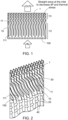
- Fig. 2 shows a cold medium layer 1 as described above and as shown in Fig. 1 combined with further hot and cold layers in a heat exchanger block.
- the example shown is a cross-flow heat exchanger, with the hot medium flowing in channels 20 and the cold medium flowing in the channels 30 defined between adjacent fins 10, 11 of the cold medium layer 1.
- additional guard properties can be achieved by also forming the leading edges 40 of the hot layers to be rounded where impact occurs at the inlet IN. This results in the inlet side IN that is presented to the incoming RAM air forming a grid of rounded bars 100, 40.
- the heat exchanger layer and heat exchanger incorporating such a layer can effectively guard against hail damage using existing features of the heat exchanger and without having to add additional components or additional mass to provide such protection. Further, pressure drop can be reduced and thermal stresses reduced.
Landscapes
- Engineering & Computer Science (AREA)
- Physics & Mathematics (AREA)
- Thermal Sciences (AREA)
- Mechanical Engineering (AREA)
- General Engineering & Computer Science (AREA)
- Chemical & Material Sciences (AREA)
- Manufacturing & Machinery (AREA)
- Materials Engineering (AREA)
- Heat-Exchange Devices With Radiators And Conduit Assemblies (AREA)
Description
- The present disclosure is concerned with additively manufactured or 3D-printed heat exchanger designs and, in particular, heat exchanger designs for use in vehicles and aircraft. A heat transfer layer according to the preamble of
claim 1 is known from documentUS 2016/230595 A1 . - Heat exchangers are used to transfer heat between mediums to provide warming or cooling. Heat exchangers are used, for example, in vehicles and aircraft for e.g. air conditioning or environmental control systems (ECS) and/or for providing cooling to electronics and electrical rack mounted equipment, or to heat or cool another medium, for example. Such heat exchangers commonly comprise a flow path/paths for hot and cold mediums. Heath transfer takes place between path surfaces. Such heat exchangers are well-known and will not be described in detail herein.
- In recent years, to improve efficiency and reduce fuel consumption, for example, heat exchangers have been developed for vehicles and aircraft. In one example, the warm medium may be bleed air from the engine and the cold medium may be ambient or so-called RAM air. The RAM air is drawn in from outside the aircraft into the heat exchanger. To provide heated air to e.g. the aircraft cabin, the cold RAM air exchanges heat with the hot bleed air in the heat exchanger and heated air at a temperature deemed comfortable for the passengers is ducted into the cabin.
- Heat exchangers typically have very thin heat exchange structures (sometimes known as fins) which define channels for the flow of hot air. The flow direction of the hot medium may be varied in relation to the heat exchanger structure and in relation to the cold medium, according to the application.
- As mentioned above, though, the fins are generally very thin, to ensure good heat exchange properties. The use of such thin fins can result in the fins becoming damaged. Sources of damage could be high inlet pressure, hailstones, and different types of debris or pollution. When the vehicle, especially an aircraft, is travelling at high speeds, the impact of hailstones on the exposed parts can be very high. Damage can result to the heat exchange fins requiring replacement of the entire heat exchanger.
- To address these risks, with conventional plate fin heat exchangers, a strip of thicker material or thicker fins have been provided at the RAM air inlet side of the heat exchanger to provide a so-called hailguard.
- A problem with such additional components is that they can cause flow distortion at the medium inlet. Having a thicker part at the inlet can create large temperature gradients through the heat exchanger layer. Further, additional parts add to the cost and complexity of manufacturing or design.
- The advent and development of 3D-printing or additive manufacturing which can be used to manufacture more and more parts and components in a whole range of applications has also led to improvements in heat exchangers. Additive manufacturing capabilities allow designers to much more easily and simply form heat exchanger plates and fins to any desired size and shape. With such capabilities, the inventors have been able to consider improved ways of providing effective protection to heat exchanger fins against hail damage in a simple and cost effective manner, whilst ensuring good thermal/heat exchange properties.
- Accordingly, there is provided a heat transfer layer of a heat exchanger, having an inlet side, IN, where a medium enters the layer and an outlet side, OUT, where the medium exits the layer, and a plurality of additively manufactured fins defining a plurality of flow channels for the medium from the inlet side to the outlet side, each fin having a leading edge adjacent the inlet side and a trailing edge adjacent the outlet side, and wherein the leading edge of a subset of the fins is thicker than the rest of the fin, and wherein the leading edge of the fins intermediate the fins of the subset of fins is recessed with respect to the inlet side compared to the leading edge of the fins of the subset of fins, wherein the subset of fins comprises every second fin.
- Also provided is a heat exchanger comprising a plurality of cold layers through which a cold medium flows and a plurality of hot layers through which a hot medium flows, wherein the cold layers comprise a heat transfer layer as defined above.
- Examples according to the disclosure will be described in more detail, with reference to the drawings. It should be noted that variations are possible within the scope of the invention as defined by the claims. The examples are described in the context of a heat exchanger for an aircraft or other vehicle using RAM air as the cooling fluid, but other fluids may be used and the design according to the disclosure may find other applications.
-
Figure 1 is a cross section of a cooling medium (here RAM air, by way of example only) layer of a heat exchanger according to the disclosure. -
Figure 2 is a 3D view of a heat exchanger block with a cooling medium layer such as shown inFig. 1 -
Figure 1 shows a cross section of alayer 1 of a heat exchanger wherefins Fig. 2 ). Between the alternate cooling layers, a heat exchanger will have hot medium layers. These layers will form flow channels for the hot medium (e.g. bleed air). The hot medium channels may provide flow of the hot fluid parallel to, but in the opposite direction, to the cold air flow, or may provide a cross-flow of the hot fluid relative to the cold fluid flow (i.e. from left to right or right to left inFig. 1 ). The present disclosure is concerned with the design of the fins of a hot fluid layer and the way in which this is incorporated into a heat exchanger block and the design of the other parts of the block can be varied as required. - The
fins fins 10 are formed to have a thickened or widened inlet end portion (leading edge) 100. According to the invention everysecond fin 10 is formed with such a thickenedend 100. - The
fins 11 located intermediate thefins 10 of the subset with the thickenedend 100 are recessed from the inlet end compared to the fins of the subset i.e. theinlet ends 111 of these intermediate fins do not extend all the way to the inlet side IN. - In one example, the thickened
ends 100 have a teardrop or bulbous shape but other thickened shapes could also be used. - The thickened
ends 100 provide a protective front to the layer with respect to the incoming cooling medium especially RAM air and therefore provide a thickened guard surface against hailstones and impact from other things. - In a preferred example, as shown, to optimally decrease the pressure drop of the incoming fluid (RAM air) the fluid channel define by the
fins straight inlet portion 12 should decrease thermal stress in high temperature applications. - To improve the heat exchange properties of the heat exchanger, the fins can be shaped such that as they progress from the inlet side IN to the outlet side OUT they become more wavy (portion 13) defining a more tortuous path for the fluid before it exits the layer. In one example, the frequency of the waves defined by the fins increases from the inlet side IN to the outlet side OUT. The greater turbulence in the medium at this
higher frequency portion 13 provides greater heat exchange with the hot medium in the adjacent layer. -
Fig. 2 shows acold medium layer 1 as described above and as shown inFig. 1 combined with further hot and cold layers in a heat exchanger block. The example shown is a cross-flow heat exchanger, with the hot medium flowing inchannels 20 and the cold medium flowing in thechannels 30 defined betweenadjacent fins cold medium layer 1. - In applications where protection against hail, high inlet pressure, any medium pollutants and the like is desired, additional guard properties can be achieved by also forming the leading
edges 40 of the hot layers to be rounded where impact occurs at the inlet IN. This results in the inlet side IN that is presented to the incoming RAM air forming a grid ofrounded bars - By using the possibilities provided by additive manufacturing to vary fin design, the heat exchanger layer and heat exchanger incorporating such a layer can effectively guard against hail damage using existing features of the heat exchanger and without having to add additional components or additional mass to provide such protection. Further, pressure drop can be reduced and thermal stresses reduced.
Claims (12)
- A heat transfer layer (1) of a heat exchanger, having an inlet side, IN, where a medium enters the layer and an outlet side, OUT, where the medium exits the layer, and a plurality of additively manufactured fins (10, 11) defining a plurality of flow channels (30) for the medium from the inlet side to the outlet side, each fin having a leading edge adjacent the inlet side and a trailing edge adjacent the outlet side, and characterized in that the leading edge (100) of a subset of the fins (10) is thicker than the rest of the fin, and wherein the leading edge (111) of the fins (11) intermediate the fins of the subset of fins is recessed with respect to the inlet side compared to the leading edge of the fins of the subset of fins, wherein the subset of fins comprises every second fin
- A heat transfer layer as claimed in claim 1, wherein the fluid flow channels (30) include a relatively straight portion (12) extending from the inlet side towards the outlet side and a relatively wavy portion (13) between the relatively straight portion and the outlet side.
- A heat transfer layer as claimed in claim 1 or 2, wherein the fluid flow channels define a wavy cross-section wherein the frequency of the wave increases from the inlet to the outlet.
- A heat transfer layer as claimed in any preceding claim, wherein the leading edges of the fins of the subset of fins have a bulbous shape.
- A heat transfer layer as claimed in any preceding claim, wherein the leading edges of the fins of the subset of fins have a teardrop shape.
- A heat exchanger comprising a plurality of cold layers through which a cold medium flows and a plurality of hot layers through which a hot medium flows, wherein the cold layers comprise a heat transfer layer as claimed in any preceding claim.
- A heat exchanger as claimed in claim 6, wherein the leading edges of the fins are reinforced at the inlet side.
- A heat exchanger as claimed in claim 6 or 7, wherein the plurality of cold layers are arranged relative to the plurality of hot layers such that the cold medium flows in a direction transverse to the direction of flow of the hot medium.
- A heat exchanger as claimed in claim 6 or 7, wherein the plurality of cold layers are arranged relative to the plurality of hot layers such that the cold medium flows in a direction parallel to but opposite to the direction of flow of the hot medium.
- A heat exchanger as claimed in any of claims 6 to 9, being a heat exchanger for a vehicle.
- A heat exchanger as claimed in claim 10, being a heat exchanger for an aircraft.
- A heat exchanger of any of claims 6 to 11, wherein the cold medium is RAM air.
Priority Applications (2)
| Application Number | Priority Date | Filing Date | Title |
|---|---|---|---|
| EP21461632.8A EP4194792B1 (en) | 2021-12-08 | 2021-12-08 | Additively manufactured heat exchanger layer |
| US18/062,354 US12292244B2 (en) | 2021-12-08 | 2022-12-06 | Additively manufactured heat exchanger layer |
Applications Claiming Priority (1)
| Application Number | Priority Date | Filing Date | Title |
|---|---|---|---|
| EP21461632.8A EP4194792B1 (en) | 2021-12-08 | 2021-12-08 | Additively manufactured heat exchanger layer |
Publications (2)
| Publication Number | Publication Date |
|---|---|
| EP4194792A1 EP4194792A1 (en) | 2023-06-14 |
| EP4194792B1 true EP4194792B1 (en) | 2024-09-11 |
Family
ID=78828088
Family Applications (1)
| Application Number | Title | Priority Date | Filing Date |
|---|---|---|---|
| EP21461632.8A Active EP4194792B1 (en) | 2021-12-08 | 2021-12-08 | Additively manufactured heat exchanger layer |
Country Status (2)
| Country | Link |
|---|---|
| US (1) | US12292244B2 (en) |
| EP (1) | EP4194792B1 (en) |
Family Cites Families (9)
| Publication number | Priority date | Publication date | Assignee | Title |
|---|---|---|---|---|
| US1752879A (en) | 1928-09-15 | 1930-04-01 | American Blower Corp | Radiator |
| US4067384A (en) | 1976-06-17 | 1978-01-10 | Miyakawa Gene K | Heat exchanger core assembly for engine cooling system |
| US6378605B1 (en) * | 1999-12-02 | 2002-04-30 | Midwest Research Institute | Heat exchanger with transpired, highly porous fins |
| US20080066888A1 (en) | 2006-09-08 | 2008-03-20 | Danaher Motion Stockholm Ab | Heat sink |
| US10371467B2 (en) * | 2012-12-05 | 2019-08-06 | Hamilton Sundstrand Corporation | Heat exchanger with variable thickness coating |
| FR3025594B1 (en) * | 2014-09-04 | 2016-09-02 | Valeo Systemes Thermiques | THERMAL EXCHANGER WITH ENHANCED DEFROSTING |
| US10907500B2 (en) * | 2015-02-06 | 2021-02-02 | Raytheon Technologies Corporation | Heat exchanger system with spatially varied additively manufactured heat transfer surfaces |
| IT201900011568A1 (en) | 2019-07-12 | 2021-01-12 | Air Hex Alonte S R L | IMPROVED RESISTANCE FIN AND RELATIVE THERMAL EXCHANGE BATTERY. |
| US20210254904A1 (en) * | 2020-02-19 | 2021-08-19 | The Boeing Company | Additively manufactured heat exchanger |
-
2021
- 2021-12-08 EP EP21461632.8A patent/EP4194792B1/en active Active
-
2022
- 2022-12-06 US US18/062,354 patent/US12292244B2/en active Active
Also Published As
| Publication number | Publication date |
|---|---|
| US12292244B2 (en) | 2025-05-06 |
| EP4194792A1 (en) | 2023-06-14 |
| US20230175791A1 (en) | 2023-06-08 |
Similar Documents
| Publication | Publication Date | Title |
|---|---|---|
| EP3553446B1 (en) | Shaped leading edge of cast plate fin heat exchanger | |
| KR100990309B1 (en) | heat transmitter | |
| US10060338B2 (en) | Intercooler | |
| US9915481B2 (en) | Fin for heat exchanger | |
| US12276466B2 (en) | Heat exchanger based on gyroid/diamond hybrid minimal surface-based disturbance structure | |
| EP2778592B1 (en) | Heat exchanger assembly having split mini-louvered fins | |
| EP2853851B1 (en) | Heat exchanger thermal fatigue stress reduction | |
| CN103557728A (en) | Improved heat exchanger | |
| JP6922645B2 (en) | Heat exchanger | |
| CN112566846B (en) | Heat exchangers for aircraft | |
| EP3537084B1 (en) | Segmented fins for a cast heat exchanger | |
| EP4365534A1 (en) | Heat exchanger including cross channel communication | |
| EP4194792B1 (en) | Additively manufactured heat exchanger layer | |
| US11391523B2 (en) | Asymmetric application of cooling features for a cast plate heat exchanger | |
| US20170114710A1 (en) | Variable air fin geometry in a charge air cooler | |
| US20250257957A1 (en) | Interwoven heat exchanger core with end face features | |
| US20140352933A1 (en) | Core assembly for a heat exchanger and method of assembling | |
| CN116398253B (en) | A turbine blade trailing edge cooling structure and turbine blade | |
| US10222136B2 (en) | Radiator for vehicle / combo cooler fin design | |
| US20120227949A1 (en) | Aerodynamic heat exchange structure | |
| CN115143829B (en) | Inlet duct inner skin radiator | |
| CN114750965B (en) | Cooling device based on bionic veins | |
| US10655530B2 (en) | Intercooler | |
| EP4023996A1 (en) | Heat exchanger | |
| JP2023122894A (en) | air conditioner |
Legal Events
| Date | Code | Title | Description |
|---|---|---|---|
| PUAI | Public reference made under article 153(3) epc to a published international application that has entered the european phase |
Free format text: ORIGINAL CODE: 0009012 |
|
| STAA | Information on the status of an ep patent application or granted ep patent |
Free format text: STATUS: THE APPLICATION HAS BEEN PUBLISHED |
|
| AK | Designated contracting states |
Kind code of ref document: A1 Designated state(s): AL AT BE BG CH CY CZ DE DK EE ES FI FR GB GR HR HU IE IS IT LI LT LU LV MC MK MT NL NO PL PT RO RS SE SI SK SM TR |
|
| STAA | Information on the status of an ep patent application or granted ep patent |
Free format text: STATUS: REQUEST FOR EXAMINATION WAS MADE |
|
| 17P | Request for examination filed |
Effective date: 20231214 |
|
| RBV | Designated contracting states (corrected) |
Designated state(s): AL AT BE BG CH CY CZ DE DK EE ES FI FR GB GR HR HU IE IS IT LI LT LU LV MC MK MT NL NO PL PT RO RS SE SI SK SM TR |
|
| GRAP | Despatch of communication of intention to grant a patent |
Free format text: ORIGINAL CODE: EPIDOSNIGR1 |
|
| STAA | Information on the status of an ep patent application or granted ep patent |
Free format text: STATUS: GRANT OF PATENT IS INTENDED |
|
| RIC1 | Information provided on ipc code assigned before grant |
Ipc: F28D 9/00 20060101ALI20240320BHEP Ipc: F28F 3/04 20060101AFI20240320BHEP |
|
| INTG | Intention to grant announced |
Effective date: 20240410 |
|
| GRAS | Grant fee paid |
Free format text: ORIGINAL CODE: EPIDOSNIGR3 |
|
| GRAA | (expected) grant |
Free format text: ORIGINAL CODE: 0009210 |
|
| STAA | Information on the status of an ep patent application or granted ep patent |
Free format text: STATUS: THE PATENT HAS BEEN GRANTED |
|
| AK | Designated contracting states |
Kind code of ref document: B1 Designated state(s): AL AT BE BG CH CY CZ DE DK EE ES FI FR GB GR HR HU IE IS IT LI LT LU LV MC MK MT NL NO PL PT RO RS SE SI SK SM TR |
|
| REG | Reference to a national code |
Ref country code: GB Ref legal event code: FG4D |
|
| REG | Reference to a national code |
Ref country code: CH Ref legal event code: EP |
|
| REG | Reference to a national code |
Ref country code: DE Ref legal event code: R096 Ref document number: 602021018626 Country of ref document: DE |
|
| REG | Reference to a national code |
Ref country code: IE Ref legal event code: FG4D |
|
| REG | Reference to a national code |
Ref country code: LT Ref legal event code: MG9D |
|
| PG25 | Lapsed in a contracting state [announced via postgrant information from national office to epo] |
Ref country code: NO Free format text: LAPSE BECAUSE OF FAILURE TO SUBMIT A TRANSLATION OF THE DESCRIPTION OR TO PAY THE FEE WITHIN THE PRESCRIBED TIME-LIMIT Effective date: 20241211 |
|
| REG | Reference to a national code |
Ref country code: NL Ref legal event code: MP Effective date: 20240911 |
|
| PG25 | Lapsed in a contracting state [announced via postgrant information from national office to epo] |
Ref country code: GR Free format text: LAPSE BECAUSE OF FAILURE TO SUBMIT A TRANSLATION OF THE DESCRIPTION OR TO PAY THE FEE WITHIN THE PRESCRIBED TIME-LIMIT Effective date: 20241212 Ref country code: FI Free format text: LAPSE BECAUSE OF FAILURE TO SUBMIT A TRANSLATION OF THE DESCRIPTION OR TO PAY THE FEE WITHIN THE PRESCRIBED TIME-LIMIT Effective date: 20240911 |
|
| PG25 | Lapsed in a contracting state [announced via postgrant information from national office to epo] |
Ref country code: BG Free format text: LAPSE BECAUSE OF FAILURE TO SUBMIT A TRANSLATION OF THE DESCRIPTION OR TO PAY THE FEE WITHIN THE PRESCRIBED TIME-LIMIT Effective date: 20240911 |
|
| PG25 | Lapsed in a contracting state [announced via postgrant information from national office to epo] |
Ref country code: LV Free format text: LAPSE BECAUSE OF FAILURE TO SUBMIT A TRANSLATION OF THE DESCRIPTION OR TO PAY THE FEE WITHIN THE PRESCRIBED TIME-LIMIT Effective date: 20240911 |
|
| PG25 | Lapsed in a contracting state [announced via postgrant information from national office to epo] |
Ref country code: HR Free format text: LAPSE BECAUSE OF FAILURE TO SUBMIT A TRANSLATION OF THE DESCRIPTION OR TO PAY THE FEE WITHIN THE PRESCRIBED TIME-LIMIT Effective date: 20240911 |
|
| PG25 | Lapsed in a contracting state [announced via postgrant information from national office to epo] |
Ref country code: RS Free format text: LAPSE BECAUSE OF FAILURE TO SUBMIT A TRANSLATION OF THE DESCRIPTION OR TO PAY THE FEE WITHIN THE PRESCRIBED TIME-LIMIT Effective date: 20241211 Ref country code: ES Free format text: LAPSE BECAUSE OF FAILURE TO SUBMIT A TRANSLATION OF THE DESCRIPTION OR TO PAY THE FEE WITHIN THE PRESCRIBED TIME-LIMIT Effective date: 20240911 |
|
| PG25 | Lapsed in a contracting state [announced via postgrant information from national office to epo] |
Ref country code: RS Free format text: LAPSE BECAUSE OF FAILURE TO SUBMIT A TRANSLATION OF THE DESCRIPTION OR TO PAY THE FEE WITHIN THE PRESCRIBED TIME-LIMIT Effective date: 20241211 Ref country code: NO Free format text: LAPSE BECAUSE OF FAILURE TO SUBMIT A TRANSLATION OF THE DESCRIPTION OR TO PAY THE FEE WITHIN THE PRESCRIBED TIME-LIMIT Effective date: 20241211 Ref country code: LV Free format text: LAPSE BECAUSE OF FAILURE TO SUBMIT A TRANSLATION OF THE DESCRIPTION OR TO PAY THE FEE WITHIN THE PRESCRIBED TIME-LIMIT Effective date: 20240911 Ref country code: HR Free format text: LAPSE BECAUSE OF FAILURE TO SUBMIT A TRANSLATION OF THE DESCRIPTION OR TO PAY THE FEE WITHIN THE PRESCRIBED TIME-LIMIT Effective date: 20240911 Ref country code: GR Free format text: LAPSE BECAUSE OF FAILURE TO SUBMIT A TRANSLATION OF THE DESCRIPTION OR TO PAY THE FEE WITHIN THE PRESCRIBED TIME-LIMIT Effective date: 20241212 Ref country code: FI Free format text: LAPSE BECAUSE OF FAILURE TO SUBMIT A TRANSLATION OF THE DESCRIPTION OR TO PAY THE FEE WITHIN THE PRESCRIBED TIME-LIMIT Effective date: 20240911 Ref country code: ES Free format text: LAPSE BECAUSE OF FAILURE TO SUBMIT A TRANSLATION OF THE DESCRIPTION OR TO PAY THE FEE WITHIN THE PRESCRIBED TIME-LIMIT Effective date: 20240911 Ref country code: BG Free format text: LAPSE BECAUSE OF FAILURE TO SUBMIT A TRANSLATION OF THE DESCRIPTION OR TO PAY THE FEE WITHIN THE PRESCRIBED TIME-LIMIT Effective date: 20240911 |
|
| REG | Reference to a national code |
Ref country code: AT Ref legal event code: MK05 Ref document number: 1723046 Country of ref document: AT Kind code of ref document: T Effective date: 20240911 |
|
| PG25 | Lapsed in a contracting state [announced via postgrant information from national office to epo] |
Ref country code: NL Free format text: LAPSE BECAUSE OF FAILURE TO SUBMIT A TRANSLATION OF THE DESCRIPTION OR TO PAY THE FEE WITHIN THE PRESCRIBED TIME-LIMIT Effective date: 20240911 |
|
| PG25 | Lapsed in a contracting state [announced via postgrant information from national office to epo] |
Ref country code: IS Free format text: LAPSE BECAUSE OF FAILURE TO SUBMIT A TRANSLATION OF THE DESCRIPTION OR TO PAY THE FEE WITHIN THE PRESCRIBED TIME-LIMIT Effective date: 20250111 Ref country code: PT Free format text: LAPSE BECAUSE OF FAILURE TO SUBMIT A TRANSLATION OF THE DESCRIPTION OR TO PAY THE FEE WITHIN THE PRESCRIBED TIME-LIMIT Effective date: 20250113 |
|
| PG25 | Lapsed in a contracting state [announced via postgrant information from national office to epo] |
Ref country code: RO Free format text: LAPSE BECAUSE OF FAILURE TO SUBMIT A TRANSLATION OF THE DESCRIPTION OR TO PAY THE FEE WITHIN THE PRESCRIBED TIME-LIMIT Effective date: 20240911 Ref country code: SM Free format text: LAPSE BECAUSE OF FAILURE TO SUBMIT A TRANSLATION OF THE DESCRIPTION OR TO PAY THE FEE WITHIN THE PRESCRIBED TIME-LIMIT Effective date: 20240911 |
|
| PG25 | Lapsed in a contracting state [announced via postgrant information from national office to epo] |
Ref country code: AT Free format text: LAPSE BECAUSE OF FAILURE TO SUBMIT A TRANSLATION OF THE DESCRIPTION OR TO PAY THE FEE WITHIN THE PRESCRIBED TIME-LIMIT Effective date: 20240911 Ref country code: EE Free format text: LAPSE BECAUSE OF FAILURE TO SUBMIT A TRANSLATION OF THE DESCRIPTION OR TO PAY THE FEE WITHIN THE PRESCRIBED TIME-LIMIT Effective date: 20240911 |
|
| PG25 | Lapsed in a contracting state [announced via postgrant information from national office to epo] |
Ref country code: PL Free format text: LAPSE BECAUSE OF FAILURE TO SUBMIT A TRANSLATION OF THE DESCRIPTION OR TO PAY THE FEE WITHIN THE PRESCRIBED TIME-LIMIT Effective date: 20240911 Ref country code: CZ Free format text: LAPSE BECAUSE OF FAILURE TO SUBMIT A TRANSLATION OF THE DESCRIPTION OR TO PAY THE FEE WITHIN THE PRESCRIBED TIME-LIMIT Effective date: 20240911 |
|
| PG25 | Lapsed in a contracting state [announced via postgrant information from national office to epo] |
Ref country code: SK Free format text: LAPSE BECAUSE OF FAILURE TO SUBMIT A TRANSLATION OF THE DESCRIPTION OR TO PAY THE FEE WITHIN THE PRESCRIBED TIME-LIMIT Effective date: 20240911 Ref country code: IT Free format text: LAPSE BECAUSE OF FAILURE TO SUBMIT A TRANSLATION OF THE DESCRIPTION OR TO PAY THE FEE WITHIN THE PRESCRIBED TIME-LIMIT Effective date: 20240911 |
|
| REG | Reference to a national code |
Ref country code: DE Ref legal event code: R097 Ref document number: 602021018626 Country of ref document: DE |
|
| PG25 | Lapsed in a contracting state [announced via postgrant information from national office to epo] |
Ref country code: MC Free format text: LAPSE BECAUSE OF FAILURE TO SUBMIT A TRANSLATION OF THE DESCRIPTION OR TO PAY THE FEE WITHIN THE PRESCRIBED TIME-LIMIT Effective date: 20240911 |
|
| PG25 | Lapsed in a contracting state [announced via postgrant information from national office to epo] |
Ref country code: DK Free format text: LAPSE BECAUSE OF FAILURE TO SUBMIT A TRANSLATION OF THE DESCRIPTION OR TO PAY THE FEE WITHIN THE PRESCRIBED TIME-LIMIT Effective date: 20240911 |
|
| PLBE | No opposition filed within time limit |
Free format text: ORIGINAL CODE: 0009261 |
|
| STAA | Information on the status of an ep patent application or granted ep patent |
Free format text: STATUS: NO OPPOSITION FILED WITHIN TIME LIMIT |
|
| REG | Reference to a national code |
Ref country code: CH Ref legal event code: PL |
|
| PG25 | Lapsed in a contracting state [announced via postgrant information from national office to epo] |
Ref country code: LU Free format text: LAPSE BECAUSE OF NON-PAYMENT OF DUE FEES Effective date: 20241208 |
|
| 26N | No opposition filed |
Effective date: 20250612 |
|
| PG25 | Lapsed in a contracting state [announced via postgrant information from national office to epo] |
Ref country code: SE Free format text: LAPSE BECAUSE OF FAILURE TO SUBMIT A TRANSLATION OF THE DESCRIPTION OR TO PAY THE FEE WITHIN THE PRESCRIBED TIME-LIMIT Effective date: 20240911 |
|
| REG | Reference to a national code |
Ref country code: BE Ref legal event code: MM Effective date: 20241231 |
|
| PG25 | Lapsed in a contracting state [announced via postgrant information from national office to epo] |
Ref country code: BE Free format text: LAPSE BECAUSE OF NON-PAYMENT OF DUE FEES Effective date: 20241231 |
|
| PG25 | Lapsed in a contracting state [announced via postgrant information from national office to epo] |
Ref country code: CH Free format text: LAPSE BECAUSE OF NON-PAYMENT OF DUE FEES Effective date: 20241231 |
|
| PG25 | Lapsed in a contracting state [announced via postgrant information from national office to epo] |
Ref country code: IE Free format text: LAPSE BECAUSE OF NON-PAYMENT OF DUE FEES Effective date: 20241208 |
|
| PGFP | Annual fee paid to national office [announced via postgrant information from national office to epo] |
Ref country code: DE Payment date: 20251126 Year of fee payment: 5 |
|
| PGFP | Annual fee paid to national office [announced via postgrant information from national office to epo] |
Ref country code: GB Payment date: 20251119 Year of fee payment: 5 |
|
| PGFP | Annual fee paid to national office [announced via postgrant information from national office to epo] |
Ref country code: FR Payment date: 20251120 Year of fee payment: 5 |