EP3553446B1 - Shaped leading edge of cast plate fin heat exchanger - Google Patents
Shaped leading edge of cast plate fin heat exchanger Download PDFInfo
- Publication number
- EP3553446B1 EP3553446B1 EP19164153.9A EP19164153A EP3553446B1 EP 3553446 B1 EP3553446 B1 EP 3553446B1 EP 19164153 A EP19164153 A EP 19164153A EP 3553446 B1 EP3553446 B1 EP 3553446B1
- Authority
- EP
- European Patent Office
- Prior art keywords
- plate
- leading edge
- recited
- terminal tip
- cast plate
- Prior art date
- Legal status (The legal status is an assumption and is not a legal conclusion. Google has not performed a legal analysis and makes no representation as to the accuracy of the status listed.)
- Active
Links
- 238000001816 cooling Methods 0.000 claims description 21
- 230000007423 decrease Effects 0.000 claims description 6
- 238000004519 manufacturing process Methods 0.000 description 4
- 238000000034 method Methods 0.000 description 3
- 238000003754 machining Methods 0.000 description 2
- 239000000463 material Substances 0.000 description 2
- 239000000654 additive Substances 0.000 description 1
- 230000000996 additive effect Effects 0.000 description 1
- 238000005266 casting Methods 0.000 description 1
- 239000012530 fluid Substances 0.000 description 1
- 239000007769 metal material Substances 0.000 description 1
- 238000012986 modification Methods 0.000 description 1
- 230000004048 modification Effects 0.000 description 1
- 230000001141 propulsive effect Effects 0.000 description 1
- 230000007704 transition Effects 0.000 description 1
Images


Classifications
-
- F—MECHANICAL ENGINEERING; LIGHTING; HEATING; WEAPONS; BLASTING
- F28—HEAT EXCHANGE IN GENERAL
- F28F—DETAILS OF HEAT-EXCHANGE AND HEAT-TRANSFER APPARATUS, OF GENERAL APPLICATION
- F28F3/00—Plate-like or laminated elements; Assemblies of plate-like or laminated elements
- F28F3/02—Elements or assemblies thereof with means for increasing heat-transfer area, e.g. with fins, with recesses, with corrugations
- F28F3/04—Elements or assemblies thereof with means for increasing heat-transfer area, e.g. with fins, with recesses, with corrugations the means being integral with the element
-
- F—MECHANICAL ENGINEERING; LIGHTING; HEATING; WEAPONS; BLASTING
- F28—HEAT EXCHANGE IN GENERAL
- F28F—DETAILS OF HEAT-EXCHANGE AND HEAT-TRANSFER APPARATUS, OF GENERAL APPLICATION
- F28F1/00—Tubular elements; Assemblies of tubular elements
- F28F1/02—Tubular elements of cross-section which is non-circular
- F28F1/025—Tubular elements of cross-section which is non-circular with variable shape, e.g. with modified tube ends, with different geometrical features
-
- F—MECHANICAL ENGINEERING; LIGHTING; HEATING; WEAPONS; BLASTING
- F28—HEAT EXCHANGE IN GENERAL
- F28D—HEAT-EXCHANGE APPARATUS, NOT PROVIDED FOR IN ANOTHER SUBCLASS, IN WHICH THE HEAT-EXCHANGE MEDIA DO NOT COME INTO DIRECT CONTACT
- F28D9/00—Heat-exchange apparatus having stationary plate-like or laminated conduit assemblies for both heat-exchange media, the media being in contact with different sides of a conduit wall
- F28D9/0093—Multi-circuit heat-exchangers, e.g. integrating different heat exchange sections in the same unit or heat-exchangers for more than two fluids
-
- F—MECHANICAL ENGINEERING; LIGHTING; HEATING; WEAPONS; BLASTING
- F28—HEAT EXCHANGE IN GENERAL
- F28F—DETAILS OF HEAT-EXCHANGE AND HEAT-TRANSFER APPARATUS, OF GENERAL APPLICATION
- F28F1/00—Tubular elements; Assemblies of tubular elements
- F28F1/10—Tubular elements and assemblies thereof with means for increasing heat-transfer area, e.g. with fins, with projections, with recesses
- F28F1/12—Tubular elements and assemblies thereof with means for increasing heat-transfer area, e.g. with fins, with projections, with recesses the means being only outside the tubular element
- F28F1/24—Tubular elements and assemblies thereof with means for increasing heat-transfer area, e.g. with fins, with projections, with recesses the means being only outside the tubular element and extending transversely
- F28F1/26—Tubular elements and assemblies thereof with means for increasing heat-transfer area, e.g. with fins, with projections, with recesses the means being only outside the tubular element and extending transversely the means being integral with the element
-
- F—MECHANICAL ENGINEERING; LIGHTING; HEATING; WEAPONS; BLASTING
- F28—HEAT EXCHANGE IN GENERAL
- F28F—DETAILS OF HEAT-EXCHANGE AND HEAT-TRANSFER APPARATUS, OF GENERAL APPLICATION
- F28F3/00—Plate-like or laminated elements; Assemblies of plate-like or laminated elements
- F28F3/08—Elements constructed for building-up into stacks, e.g. capable of being taken apart for cleaning
-
- F—MECHANICAL ENGINEERING; LIGHTING; HEATING; WEAPONS; BLASTING
- F28—HEAT EXCHANGE IN GENERAL
- F28F—DETAILS OF HEAT-EXCHANGE AND HEAT-TRANSFER APPARATUS, OF GENERAL APPLICATION
- F28F9/00—Casings; Header boxes; Auxiliary supports for elements; Auxiliary members within casings
- F28F9/02—Header boxes; End plates
-
- F—MECHANICAL ENGINEERING; LIGHTING; HEATING; WEAPONS; BLASTING
- F28—HEAT EXCHANGE IN GENERAL
- F28F—DETAILS OF HEAT-EXCHANGE AND HEAT-TRANSFER APPARATUS, OF GENERAL APPLICATION
- F28F2255/00—Heat exchanger elements made of materials having special features or resulting from particular manufacturing processes
- F28F2255/14—Heat exchanger elements made of materials having special features or resulting from particular manufacturing processes molded
Definitions
- a plate fin heat exchanger includes adjacent flow paths that transfer heat from a hot flow to a cooling flow.
- the flow paths are defined by a combination of plates and fins that are arranged to transfer heat from one flow to another flow.
- the plates and fins are created from sheet metal material brazed together to define the different flow paths.
- Thermal gradients present in the sheet material create stresses that can be very high in certain locations. The stresses are typically largest in one corner where the hot side flow first meets the coldest portion of the cooling flow. In an opposite corner where the coldest hot side flow meets the hottest cold side flow the temperature difference is much less resulting in unbalanced stresses across the heat exchanger structure. Increasing temperatures and pressures can result in stresses on the structure that can exceed material and assembly capabilities.
- Turbine engine manufactures utilize heat exchangers throughout the engine to cool and condition airflow for cooling and other operational needs. Improvements to turbine engines have enabled increases in operational temperatures and pressures. The increases in temperatures and pressures improve engine efficiency but also increase demands on all engine components including heat exchangers.
- Turbine engine manufacturers continue to seek further improvements to engine performance including improvements to thermal, transfer and propulsive efficiencies.
- EP 0 519 334 A2 discloses a prior art flat tube heat exchanger and process for manufacturing same.
- US 4 171 015 A discloses a prior art heat exchanger tube and method of making same.
- EP 0 132 237 A2 discloses a prior art element for exchanging heat between fluids, and a radiator constructed with the said heat exchange element.
- a cast plate for a plate fin heat exchanger as claimed in claim 1.
- a plurality of fin portions extend outward from a top surface and a bottom surface of the plate portion.
- Each of the plurality of fin portions include a forward most end that is spaced apart from the terminal tip.
- the forward lost end of each of the plurality of fin portions is tapered in a direction away from the terminal tip.
- the plate portion includes a top surface parallel to a bottom surface, and the varying radius tapers from both the top surface and bottom surface at an intersection point spaced apart from the terminal tip and at least one of the plurality of passages is disposed at least partially forward of the intersection point.
- a uniform wall thickness is included between each of the plurality of passages and the top and bottom surfaces of the plate portion.
- one of the plurality of internal passages includes a leading edge passage disposed closest to the leading edge.
- the leading edge passage includes a width different than each of the other plurality of passages.
- the plurality of passages are one of a stadium shape, elliptical shape, oval shape and rectilinear shape in cross-section.
- the plate in another embodiment according to any of the previous embodiments, includes a plurality of plate portions extending between a common inlet face and a common outlet face.
- a cooling flow channel is disposed between two of the plurality of plate portions and includes fins extending from top and bottom surface of each of the plurality of plate portions.
- the trailing edge includes a second terminal tip and a trailing edge surface with a varying radius that decreases in a direction toward the second terminal tip.
- a trailing edge passage is disposed at least partially aft of an intersection point between the top and bottom surfaces and the trailing edge surface.
- the plate includes a single unitary part.
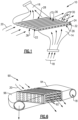
- an example heat exchanger 10 is schematically shown and includes a plate 12 that is attached at an inlet side 26 to an inlet manifold 14.
- An outlet manifold 16 is attached to an outlet side 28 of the plate 12.
- Incoming hot airflow 18 is communicated to a plurality of internal passages through the plate 12 through the inlet manifold 14. Cooled airflow exits through the outlet side 28 into the outlet manifold 16.
- a cooling airflow 20 flows over a top surface 36 and a bottom surface 38 of the plate 12.
- the top surface 36 and bottom surface 38 each include a plurality of fin portions 30.
- the fin portions 30 extend outward to provide additional surface area for the transfer of thermal energy between the hot flow 18 and the cooling flow 20.
- the example plate 12 is a single cast unitary part including the fin portions 30 that extend from a plate portion 32.
- the plate portion 32 includes a leading edge 22 and trailing edge 24.
- the cooling airflow 20 initially encounters the plate 12 at the leading edge 22 and flows over the top and bottom surfaces 36, 38 toward the trailing edge 24. It should be appreciated that although one example plate 12 is disclosed as cast, other fabrication techniques and methods could be used, such a machining, and are within the contemplation of this disclosure.
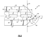
- the example the leading edge 22 includes a terminal tip 42.
- the terminal tip 42 is the extreme most leading edge portion of the plate 12 and is the first part to encounter the cooling airflow 20.
- the example leading edge 22 includes the terminal tip 42 and includes a configuration provided to increase durability and provide additional survivability in the event of impact by debris within cooling airflow stream 20.
- the plate 12 includes the plurality of passages 40 that extend between a corresponding plurality of inlets 34 on the inlet side 26 to a corresponding plurality of outlets 35 on the outlet side 28.
- Each of the plurality of passages 40 extending through the plate portion 32 include a cross-sectional shape.
- each of the passages includes a stadium shape in cross section.
- each of the passages 40 may be of a different cross-section including oval, elliptical and rectilinear shapes in cross-section. Moreover other shapes as are known and provided in the art may also be utilized in or within contemplation of this disclosure.
- the leading edge 22 of the example plate portion 12 includes a leading edge passage 44 which has a different configuration than the other passages 40 through the plate portion 32.
- the example plate portion 32 includes the leading edge passage 44 that extends into the leading edge 22.
- the example leading edge 22 includes an outer surface 50 that has a continually varying radius that decreases in a direction towards the terminal tip 42.
- the plate portion 32 includes a flat top surface 36 that transitions to the varying radius towards the terminal tip 42.
- the varying radius begins at an intersection plane 46. Beginning at the intersection plane 46 toward the terminal tip 42, the surface 50 includes the varying radius that is schematically indicated at 48.
- the varying radius 48 provides the desired shape of the leading edge 22 to improve survivability in the case of impact and also provides improved airflow characteristics.
- the radius 48 is the same between the top surface and the bottom surface 38, however, the radius may be different between top and bottom surfaces to provide an asymmetric leading edge 22 about a horizontal plane 35.
- the varying radius 48 maintains laminar flow characteristics of the cooling flow 20 as it flows along the top and bottom surfaces 36, 38.
- other shapes may be utilized within the contemplation of this disclosure that include different varying radii that decreases towards the terminal tip 42 to provide improved air flow characteristics that maintain a laminar flow along the top and bottom surfaces 36, 38 of the plate portion 32.
- the leading edge passage 44 extends forward past the intersection plane 46 into the leading edge 22.
- Each of the plurality of passages 40 include a common width 58.
- the leading edge passage 44 includes a width 60 that is different than the width 58 of the other passages 40 not disposed within the leading edge 22.
- the width 60 is greater than the width 58, however, the width 60 may be smaller to provide the desired wall thickness within the leading edge 22.
- the leading edge passage 44 also includes a wall 56 within the leading edge 22 forward of the intersection plane 46.
- the wall 56 includes thicknesses 52, 55, and 54 that increase in a direction towards the terminal tip 42 beginning from the intersection plane 46. The increased thickness of the wall 56 in the direction towards the terminal tip 42 improves durability and survivability of the case plate 12.
- the wall thicknesses 52, 55, and 54 are shown in the disclosed example as symmetric about a horizontal plane 45, the wall thicknesses 52, 55, and 54 may vary asymmetrically about the plane 45 to provide a desired impact protection and heat transfer.
- Fin portions 30 disposed on the top and bottom surfaces 36, 38 of the plate portion 32 extend past the intersection plane 46 and include a tapered edge 33 forward of the intersection plane 46 that begins aft of the intersection plane 46.
- the tapered edge 33 of the fin portions 30 also improves durability and airflow characteristics.
- Each of the fin portions 30 include a forward most end 35 that is spaced apart from the terminal tip 42.
- the tapered edge 33 begins at the forward most end 35 that is spaced apart from the terminal tip 42.
- the trailing edge 24 of the disclosed plate 12 embodiment includes a configuration similar to that provided in the leading edge 22.
- the trailing edge 24 includes a trailing edge terminal tip 64.
- the terminal tip 64 is at the aft-most portion of the plate portion 32 such that it is last physical part of the plate 12 that encounters cooling airflow 20.
- a surface 68 between a trailing edge intersection plane 70 and the terminal tip 64 as indicated at 66 is a continuously varying radius.
- the trailing edge surface 68 includes a radius that decreases in a direction from the intersection plane 70 in a direction towards the terminal tip 64.
- the varying radius of surface 68 may be the same as that provided at the leading edge 22 to provide a uniformity of the plate portions 32. Alternatively, the varying radius of surface 68 may be different to provide the airflow characteristics with regard to the cooling airflow 20 flowing over the trailing edge 24.
- the trailing edge 24 includes a trailing edge passage 78 which is the aft-most passage of the plurality of passages 40.
- the trailing edge passage 78 includes a width 80 that is greater than the common width 58 of the other plurality of passages 40.
- the trailing edge passage 78 extends past the trailing edge intersection plane 70 into the trailing edge 24.
- the trailing edge 24 includes a trailing edge wall 75 with a thickness that increases in a direction towards the terminal tip 64.
- the wall 75 includes varying wall thicknesses 76, 74 and 72 that increase in a direction toward the terminal tip 64.
- FIG. 6 another example heat exchanger assembly 90 is disclosed and includes a plate 92 that includes a plurality of plate portions 98 that are formed as a single unitary part.
- An inlet manifold 94 and outlet manifold 96 communicate hot airflow through the cast plate 92 in the same manner as the heat exchanger assembly 10 shown in Figure 1 .
- the example plate 92 is shown in a perspective view and includes four plate portions 98 and three cooling channels 100 defined between the plate portions 98.
- Each of the cooling channels 100 is a space for cooling airflow 20 and includes fin portions 102.
- the fin portions 102 extend from top and bottom surfaces of each of the plate portions 98 to provide an increase in surface area to improve thermal transfer between the hot flow 18 and cooling airflow 20.
- the example plate 92 includes a leading edge 112 and a trailing edge 110.
- the leading edge 112 and trailing edge 110 include the same features and configuration as is disclosed in previous Figures 4 and 5 .
- each of the plate portions 98 includes a terminal tip 42 and a leading edge 22 wherein the leading edge 22 includes a continuously varying radius between an intersection plane and the terminal tip 42.
- a leading edge passage 44 extends past the intersection 46 into the leading edge 22 and a trailing edge passage 78 extends aft past an intersection 70 into the trailing edge 24.
- the leading edge passage 44 and the trailing edge 24 for each of the plates 92 includes a varying wall thickness that increases in thickness in a direction toward the corresponding terminal tips 42 64.
- the example plate 92 includes a plurality of plate portions 98 that each define a plurality of passages 116 that extend between a corresponding plurality of inlets 114 and outlets 108.
- Each of the outlets 108 open onto a common outlet face 104.
- the common outlet face 104 is a flat plane through which each of the outlets 108 for each of the four plate portions 98 is disposed.
- the outlet face 104 is surrounded by an outlet perimeter 115.
- the plurality of inlets 114 open onto an inlet face 106.
- the inlet face 106 is similar to the outlet face 104 and includes the plurality of inlets 114 that open and are disposed within the inlet face 106 surrounded by an inlet perimeter 117.
- Figure 8 illustrates the plate 120 that includes two plate portions 98.
- Figure 9 disclosures the plate 122 with three plate portions 98.
- the plate 120 includes a single cooling channel 100 disposed between the two plate portions 98.
- Each of the plate portions 98 include the leading and trailing edge configurations as described above in Figures 4 and 5 .
- the plate 122 disclosed in Figure 9 includes three plate portions 98 and two cooling channels 100 disposed between the three plate portions 98.
- the plate portions 98 include leading edges 112 and trailing edges 110 that include the same configuration and features as disclosed and described in Figures 4 and 5 above.
- Both the plates 120 and 122 include an inlet face 106 with a plurality of inlets 114 and an outlet face 104 with a plurality of outlets 108.
- Each of the inlet and outlet faces 106, 104 define a common plane for the corresponding inlets 114 and outlets 108.
- the example disclosed plates 12, 92 are formed as single piece unitary structure and may be formed using casting, additive manufacturing as well as traditional machining.
- the disclosed heat exchanger assembly include a single unitary plate portion with features on both the leading and trailing edge that improve cooling airflow, thermal transfer and survivability.
Description
- A plate fin heat exchanger includes adjacent flow paths that transfer heat from a hot flow to a cooling flow. The flow paths are defined by a combination of plates and fins that are arranged to transfer heat from one flow to another flow. The plates and fins are created from sheet metal material brazed together to define the different flow paths. Thermal gradients present in the sheet material create stresses that can be very high in certain locations. The stresses are typically largest in one corner where the hot side flow first meets the coldest portion of the cooling flow. In an opposite corner where the coldest hot side flow meets the hottest cold side flow the temperature difference is much less resulting in unbalanced stresses across the heat exchanger structure. Increasing temperatures and pressures can result in stresses on the structure that can exceed material and assembly capabilities.
- Turbine engine manufactures utilize heat exchangers throughout the engine to cool and condition airflow for cooling and other operational needs. Improvements to turbine engines have enabled increases in operational temperatures and pressures. The increases in temperatures and pressures improve engine efficiency but also increase demands on all engine components including heat exchangers.
- Turbine engine manufacturers continue to seek further improvements to engine performance including improvements to thermal, transfer and propulsive efficiencies.
-
EP 0 519 334 A2 discloses a prior art flat tube heat exchanger and process for manufacturing same. -
DE 20 2004 011489 U1 discloses a prior art heat exchanger for turbocharged IC engines. -
US 4 171 015 A discloses a prior art heat exchanger tube and method of making same. -
EP 0 132 237 A2 discloses a prior art element for exchanging heat between fluids, and a radiator constructed with the said heat exchange element. -
DE 10 331 518 A1 discloses a prior art heat exchanger for cooling air. - In accordance with a first aspect of the present invention, there is provided a cast plate for a plate fin heat exchanger as claimed in claim 1.
- In another embodiment according to the previous embodiment, a plurality of fin portions extend outward from a top surface and a bottom surface of the plate portion. Each of the plurality of fin portions include a forward most end that is spaced apart from the terminal tip.
- In another embodiment according to any of the previous embodiments, the forward lost end of each of the plurality of fin portions is tapered in a direction away from the terminal tip.
- In another embodiment according to any of the previous embodiments, the plate portion includes a top surface parallel to a bottom surface, and the varying radius tapers from both the top surface and bottom surface at an intersection point spaced apart from the terminal tip and at least one of the plurality of passages is disposed at least partially forward of the intersection point.
- In another embodiment according to any of the previous embodiments, a uniform wall thickness is included between each of the plurality of passages and the top and bottom surfaces of the plate portion.
- In another embodiment according to any of the previous embodiments, one of the plurality of internal passages includes a leading edge passage disposed closest to the leading edge. The leading edge passage includes a width different than each of the other plurality of passages.
- In another embodiment according to any of the previous embodiments, the plurality of passages are one of a stadium shape, elliptical shape, oval shape and rectilinear shape in cross-section.
- In another embodiment according to any of the previous embodiments, the plate includes a plurality of plate portions extending between a common inlet face and a common outlet face. A cooling flow channel is disposed between two of the plurality of plate portions and includes fins extending from top and bottom surface of each of the plurality of plate portions.
- In another embodiment according to any of the previous embodiments, the trailing edge includes a second terminal tip and a trailing edge surface with a varying radius that decreases in a direction toward the second terminal tip.
- In another embodiment according to any of the previous embodiments, a trailing edge passage is disposed at least partially aft of an intersection point between the top and bottom surfaces and the trailing edge surface.
- In another embodiment according to any of the previous embodiments, the plate includes a single unitary part.
- In accordance with a second aspect of the present invention, there is provided a heat exchanger assembly as claimed in
claim 12. - Although the different examples have the specific components shown in the illustrations, embodiments of this disclosure are not limited to those particular combinations. It is possible to use some of the components or features from one of the examples in combination with features or components from another one of the examples.
- These and other features disclosed herein can be best understood from the following specification and drawings, the following of which is a brief description.
-
-
Figure 1 is a schematic view of an example heat exchanger embodiment. -
Figure 2 is a perspective view of an example cast plate embodiment. -
Figure 3 is an enlarged view of a leading edge of the cast plate. -
Figure 4 is another enlarged view of the leading of edge of the cast plate. -
Figure 5 is an enlarged view of the trailing edge of the example cast plate. -
Figure 6 is a perspective view of another example heat exchanger embodiment. -
Figure 7 is a perspective view of another cast plate embodiment. -
Figure 8 is a perspective view of another cast plate embodiment. -
Figure 9 is yet another perspective view of another cast plate embodiment. - Referring to
Figure 1 , anexample heat exchanger 10 is schematically shown and includes aplate 12 that is attached at aninlet side 26 to aninlet manifold 14. Anoutlet manifold 16 is attached to anoutlet side 28 of theplate 12. Incominghot airflow 18 is communicated to a plurality of internal passages through theplate 12 through theinlet manifold 14. Cooled airflow exits through theoutlet side 28 into theoutlet manifold 16. Acooling airflow 20 flows over atop surface 36 and abottom surface 38 of theplate 12. Thetop surface 36 andbottom surface 38 each include a plurality offin portions 30. Thefin portions 30 extend outward to provide additional surface area for the transfer of thermal energy between thehot flow 18 and thecooling flow 20. - The
example plate 12 is a single cast unitary part including thefin portions 30 that extend from aplate portion 32. Theplate portion 32 includes a leadingedge 22 andtrailing edge 24. Thecooling airflow 20 initially encounters theplate 12 at the leadingedge 22 and flows over the top andbottom surfaces trailing edge 24. It should be appreciated that although oneexample plate 12 is disclosed as cast, other fabrication techniques and methods could be used, such a machining, and are within the contemplation of this disclosure. - Referring to
Figures 2 and 3 with continued reference toFigure 1 , the example the leadingedge 22 includes aterminal tip 42. Theterminal tip 42 is the extreme most leading edge portion of theplate 12 and is the first part to encounter thecooling airflow 20. Theexample leading edge 22 includes theterminal tip 42 and includes a configuration provided to increase durability and provide additional survivability in the event of impact by debris withincooling airflow stream 20. - The
plate 12 includes the plurality ofpassages 40 that extend between a corresponding plurality ofinlets 34 on theinlet side 26 to a corresponding plurality ofoutlets 35 on theoutlet side 28. Each of the plurality ofpassages 40 extending through theplate portion 32 include a cross-sectional shape. In the disclosed example each of the passages includes a stadium shape in cross section. It should appreciated that each of thepassages 40 may be of a different cross-section including oval, elliptical and rectilinear shapes in cross-section. Moreover other shapes as are known and provided in the art may also be utilized in or within contemplation of this disclosure. The leadingedge 22 of theexample plate portion 12 includes aleading edge passage 44 which has a different configuration than theother passages 40 through theplate portion 32. - Referring to
Figure 4 with continued reference toFigure 3 , theexample plate portion 32 includes theleading edge passage 44 that extends into the leadingedge 22. Theexample leading edge 22 includes anouter surface 50 that has a continually varying radius that decreases in a direction towards theterminal tip 42. Theplate portion 32 includes a flattop surface 36 that transitions to the varying radius towards theterminal tip 42. The varying radius begins at anintersection plane 46. Beginning at theintersection plane 46 toward theterminal tip 42, thesurface 50 includes the varying radius that is schematically indicated at 48. The varyingradius 48 provides the desired shape of the leadingedge 22 to improve survivability in the case of impact and also provides improved airflow characteristics. In the disclosed example, theradius 48 is the same between the top surface and thebottom surface 38, however, the radius may be different between top and bottom surfaces to provide an asymmetricleading edge 22 about ahorizontal plane 35. - In this example the varying
radius 48 maintains laminar flow characteristics of the coolingflow 20 as it flows along the top andbottom surfaces terminal tip 42 to provide improved air flow characteristics that maintain a laminar flow along the top andbottom surfaces plate portion 32. - The
leading edge passage 44 extends forward past theintersection plane 46 into the leadingedge 22. Each of the plurality ofpassages 40 include acommon width 58. In this example embodiment theleading edge passage 44 includes awidth 60 that is different than thewidth 58 of theother passages 40 not disposed within the leadingedge 22. In this example thewidth 60 is greater than thewidth 58, however, thewidth 60 may be smaller to provide the desired wall thickness within the leadingedge 22. - The
leading edge passage 44 also includes awall 56 within the leadingedge 22 forward of theintersection plane 46. Thewall 56 includesthicknesses terminal tip 42 beginning from theintersection plane 46. The increased thickness of thewall 56 in the direction towards theterminal tip 42 improves durability and survivability of thecase plate 12. Although the wall thicknesses 52, 55, and 54 are shown in the disclosed example as symmetric about ahorizontal plane 45, the wall thicknesses 52, 55, and 54 may vary asymmetrically about theplane 45 to provide a desired impact protection and heat transfer. -
Fin portions 30 disposed on the top andbottom surfaces plate portion 32 extend past theintersection plane 46 and include atapered edge 33 forward of theintersection plane 46 that begins aft of theintersection plane 46. The taperededge 33 of thefin portions 30 also improves durability and airflow characteristics. Each of thefin portions 30 include a forward most end 35 that is spaced apart from theterminal tip 42. The taperededge 33 begins at the forward most end 35 that is spaced apart from theterminal tip 42. - Referring to
Figure 5 with continued reference toFigure 4 , the trailingedge 24 of the disclosedplate 12 embodiment includes a configuration similar to that provided in the leadingedge 22. The trailingedge 24 includes a trailingedge terminal tip 64. Theterminal tip 64 is at the aft-most portion of theplate portion 32 such that it is last physical part of theplate 12 thatencounters cooling airflow 20. Asurface 68 between a trailingedge intersection plane 70 and theterminal tip 64 as indicated at 66 is a continuously varying radius. The trailingedge surface 68 includes a radius that decreases in a direction from theintersection plane 70 in a direction towards theterminal tip 64. The varying radius ofsurface 68 may be the same as that provided at theleading edge 22 to provide a uniformity of theplate portions 32. Alternatively, the varying radius ofsurface 68 may be different to provide the airflow characteristics with regard to thecooling airflow 20 flowing over the trailingedge 24. - Additionally the trailing
edge 24 includes a trailingedge passage 78 which is the aft-most passage of the plurality ofpassages 40. In this example the trailingedge passage 78 includes awidth 80 that is greater than thecommon width 58 of the other plurality ofpassages 40. Moreover the trailingedge passage 78 extends past the trailingedge intersection plane 70 into the trailingedge 24. The trailingedge 24 includes a trailingedge wall 75 with a thickness that increases in a direction towards theterminal tip 64. Thewall 75 includes varying wall thicknesses 76, 74 and 72 that increase in a direction toward theterminal tip 64. - Referring to
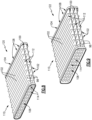
Figure 6 another exampleheat exchanger assembly 90 is disclosed and includes aplate 92 that includes a plurality ofplate portions 98 that are formed as a single unitary part. Aninlet manifold 94 andoutlet manifold 96 communicate hot airflow through thecast plate 92 in the same manner as theheat exchanger assembly 10 shown inFigure 1 . - Referring to
Figure 7 with continued reference toFigure 6 , theexample plate 92 is shown in a perspective view and includes fourplate portions 98 and three coolingchannels 100 defined between theplate portions 98. Each of the coolingchannels 100 is a space for coolingairflow 20 and includesfin portions 102. Thefin portions 102 extend from top and bottom surfaces of each of theplate portions 98 to provide an increase in surface area to improve thermal transfer between thehot flow 18 andcooling airflow 20. - The
example plate 92 includes aleading edge 112 and a trailingedge 110. Theleading edge 112 and trailingedge 110 include the same features and configuration as is disclosed in previousFigures 4 and5 . Accordingly, each of theplate portions 98 includes aterminal tip 42 and aleading edge 22 wherein the leadingedge 22 includes a continuously varying radius between an intersection plane and theterminal tip 42. Aleading edge passage 44 extends past theintersection 46 into the leadingedge 22 and a trailingedge passage 78 extends aft past anintersection 70 into the trailingedge 24. Additionally, theleading edge passage 44 and the trailingedge 24 for each of theplates 92 includes a varying wall thickness that increases in thickness in a direction toward the correspondingterminal tips 42 64. - The
example plate 92 includes a plurality ofplate portions 98 that each define a plurality ofpassages 116 that extend between a corresponding plurality ofinlets 114 andoutlets 108. Each of theoutlets 108 open onto acommon outlet face 104. Thecommon outlet face 104 is a flat plane through which each of theoutlets 108 for each of the fourplate portions 98 is disposed. Theoutlet face 104 is surrounded by anoutlet perimeter 115. Similarly, the plurality ofinlets 114 open onto aninlet face 106. Theinlet face 106 is similar to theoutlet face 104 and includes the plurality ofinlets 114 that open and are disposed within theinlet face 106 surrounded by aninlet perimeter 117. - Referring to
Figures 8 and 9 additionalcast plate embodiments Figure 8 illustrates theplate 120 that includes twoplate portions 98.Figure 9 disclosures theplate 122 with threeplate portions 98. Theplate 120 includes asingle cooling channel 100 disposed between the twoplate portions 98. Each of theplate portions 98 include the leading and trailing edge configurations as described above inFigures 4 and5 . - The
plate 122 disclosed inFigure 9 includes threeplate portions 98 and two coolingchannels 100 disposed between the threeplate portions 98. Theplate portions 98 include leadingedges 112 and trailingedges 110 that include the same configuration and features as disclosed and described inFigures 4 and5 above. Both theplates inlet face 106 with a plurality ofinlets 114 and anoutlet face 104 with a plurality ofoutlets 108. Each of the inlet and outlet faces 106, 104 define a common plane for the correspondinginlets 114 andoutlets 108. - The example disclosed
plates - Although an example embodiment has been disclosed, a worker of ordinary skill in this art would recognize that certain modifications would come within the scope of this disclosure. For that reason, the following claims should be studied to determine the scope and content of this disclosure.
Claims (12)
- A cast plate (12, 92) for a plate fin heat exchanger comprising:a plate portion (32, 98) having a leading edge (22, 112), trailing edge (24, 110), an inlet side (26) and an outlet side (28), wherein the leading edge (22, 112) of the plate portion (32, 98) includes a terminal tip (42) and a varying radius (48) that decreases in a direction toward the terminal tip (42), the plate portion (32, 98) includes a plurality of internal passages (40, 116) extending between a corresponding plurality of inlets (34, 114) on the inlet side (26) and a corresponding plurality of outlets (35, 108) on the outlet side (28), and one of the plurality of internal passages (40, 116) includes a leading edge passage (44) disposed closest to the leading edge (22, 112),characterised in that:
a wall thickness between the leading edge passage (44) and the leading edge (22, 112) increases in a direction toward the terminal tip (42). - The cast plate as recited in claim 1, including a plurality of fin portions (30, 102) extending outward from a top surface (36) and a bottom surface (38) of the plate portion (32, 98), wherein each of the plurality of fin portions (30, 102) include a forward most end (35) that is spaced apart from the terminal tip (42).
- The cast plate as recited in claim 2, wherein the forward most end (35) of each of the plurality of fin portions (30, 102) is tapered in a direction away from the terminal tip (42).
- The cast plate as recited in any preceding claim, wherein the plate portion (32, 98) includes a or the top surface (36) parallel to a or the bottom surface (38), and the varying radius (48) tapers from both the top surface (36) and bottom surface (38) at an intersection point spaced apart from the terminal tip (42) and at least one of the plurality of passages (40, 116) is disposed at least partially forward of the intersection point.
- The cast plate as recited in any preceding claim, including a uniform wall thickness between each of the plurality of passages (40, 116) and the top and bottom surfaces (36, 38) of the plate portion (32, 98).
- The cast plate as recited in any preceding claim, wherein the leading edge passage (44) includes a width (60) different than each of the other plurality of passages (40, 116).
- The cast plate as recited in any preceding claim, wherein the plurality of passages (40, 116) are one of a stadium shape, elliptical shape, oval shape and rectilinear shape in cross-section.
- The cast plate as recited in any preceding claim, wherein the plate comprises a plurality of plate portions (98) extending between a common inlet face (106) and a common outlet face (104), wherein a cooling flow channel (100) is disposed between two of the plurality of plate portions (98) and includes fin portions (102) extending from top and bottom surfaces of each of the plurality of plate portions (98).
- The cast plate as recited in any preceding claim, wherein the trailing edge (24, 110) includes a second terminal tip (64) and a trailing edge surface (68) with a varying radius (66) that decreases in a direction toward the second terminal tip (64).
- The cast plate as recited in claim 9, including a trailing edge passage (78) disposed at least partially aft of an intersection point between the top and bottom surfaces (36, 38) and the trailing edge surface (68).
- The heat exchanger assembly as recited in any preceding claim, wherein the cast plate (12, 92) comprises a single unitary part.
- A heat exchanger assembly (10, 90) comprising:the cast plate (12, 92) as recited in any preceding claim;an inlet manifold (14, 94) on the inlet side (26); andan outlet manifold (16, 96) on the outlet side (28).
Applications Claiming Priority (2)
| Application Number | Priority Date | Filing Date | Title |
|---|---|---|---|
| US201862647030P | 2018-03-23 | 2018-03-23 | |
| US16/271,178 US10962306B2 (en) | 2018-03-23 | 2019-02-08 | Shaped leading edge of cast plate fin heat exchanger |
Publications (2)
| Publication Number | Publication Date |
|---|---|
| EP3553446A1 EP3553446A1 (en) | 2019-10-16 |
| EP3553446B1 true EP3553446B1 (en) | 2023-05-10 |
Family
ID=65894891
Family Applications (1)
| Application Number | Title | Priority Date | Filing Date |
|---|---|---|---|
| EP19164153.9A Active EP3553446B1 (en) | 2018-03-23 | 2019-03-20 | Shaped leading edge of cast plate fin heat exchanger |
Country Status (2)
| Country | Link |
|---|---|
| US (1) | US10962306B2 (en) |
| EP (1) | EP3553446B1 (en) |
Families Citing this family (5)
| Publication number | Priority date | Publication date | Assignee | Title |
|---|---|---|---|---|
| US11391523B2 (en) * | 2018-03-23 | 2022-07-19 | Raytheon Technologies Corporation | Asymmetric application of cooling features for a cast plate heat exchanger |
| DE102018003479A1 (en) * | 2018-04-27 | 2019-10-31 | Linde Aktiengesellschaft | Plate heat exchanger, process plant and process |
| US11448132B2 (en) | 2020-01-03 | 2022-09-20 | Raytheon Technologies Corporation | Aircraft bypass duct heat exchanger |
| US11674758B2 (en) | 2020-01-19 | 2023-06-13 | Raytheon Technologies Corporation | Aircraft heat exchangers and plates |
| US11525637B2 (en) | 2020-01-19 | 2022-12-13 | Raytheon Technologies Corporation | Aircraft heat exchanger finned plate manufacture |
Citations (1)
| Publication number | Priority date | Publication date | Assignee | Title |
|---|---|---|---|---|
| DE10331518A1 (en) * | 2002-07-12 | 2004-01-22 | Denso Corp., Kariya | Heat exchanger for cooling air |
Family Cites Families (9)
| Publication number | Priority date | Publication date | Assignee | Title |
|---|---|---|---|---|
| US2325036A (en) | 1941-07-22 | 1943-07-27 | Harold W Case | Radiator core tube |
| US4171015A (en) | 1977-03-28 | 1979-10-16 | Caterpillar Tractor Co. | Heat exchanger tube and method of making same |
| EP0132237A3 (en) | 1983-06-30 | 1986-02-05 | Renato Ferroni | Element for exchanging heat between fluids, and radiator constructed with the said heat exchange element |
| DE4201791A1 (en) * | 1991-06-20 | 1993-07-29 | Thermal Waerme Kaelte Klima | FLAT TUBES FOR INSTALLATION IN A FLAT TUBE HEAT EXCHANGER AND METHOD FOR SEPARATING THE FLAT TUBES |
| DE202004011489U1 (en) | 2004-07-20 | 2005-12-08 | Autokühler GmbH & Co. KG | Heat exchanger especially for turbocharged IC engine has pairs of parallel plates linked by edge profile strips with improved aerodynamic shapes |
| EP2452907A1 (en) | 2010-11-11 | 2012-05-16 | Inventio AG | Elevator Safety Circuit |
| US20130008186A1 (en) | 2011-07-07 | 2013-01-10 | Newman Michael D | Cryogen heat plate heat exchanger |
| JP5907752B2 (en) * | 2012-02-20 | 2016-04-26 | 株式会社ケーヒン・サーマル・テクノロジー | Heat exchanger |
| DE102016001607A1 (en) * | 2015-05-01 | 2016-11-03 | Modine Manufacturing Company | Liquid-to-refrigerant heat exchanger and method of operating the same |
-
2019
- 2019-02-08 US US16/271,178 patent/US10962306B2/en active Active
- 2019-03-20 EP EP19164153.9A patent/EP3553446B1/en active Active
Patent Citations (1)
| Publication number | Priority date | Publication date | Assignee | Title |
|---|---|---|---|---|
| DE10331518A1 (en) * | 2002-07-12 | 2004-01-22 | Denso Corp., Kariya | Heat exchanger for cooling air |
Also Published As
| Publication number | Publication date |
|---|---|
| US10962306B2 (en) | 2021-03-30 |
| EP3553446A1 (en) | 2019-10-16 |
| US20190293366A1 (en) | 2019-09-26 |
Similar Documents
| Publication | Publication Date | Title |
|---|---|---|
| EP3553446B1 (en) | Shaped leading edge of cast plate fin heat exchanger | |
| EP3499170B1 (en) | Heat exchanger inlet | |
| EP3553447B1 (en) | Heat augmentation features in a cast heat exchanger | |
| EP3244153B1 (en) | Heat exchanger | |
| EP2843213B1 (en) | Heat exchanger for aircraft engine | |
| US11079181B2 (en) | Cast plate heat exchanger with tapered walls | |
| US20190277579A1 (en) | High temperature plate fin heat exchanger | |
| EP3258204A1 (en) | Header for a heat exchanger | |
| EP3537085A1 (en) | Ganged plate stack in cast plate fin heat exchanger | |
| JPH0384396A (en) | Heat exchanger | |
| KR20140118878A (en) | Air to air heat exchanger | |
| US20160061535A1 (en) | Heat exchanger | |
| EP3537084B1 (en) | Segmented fins for a cast heat exchanger | |
| EP3553449B1 (en) | Asymmetric application of cooling features for a cast plate heat exchanger | |
| EP3889533B1 (en) | Mixing between flow channels of cast plate heat exchanger | |
| JP6895497B2 (en) | Rib heat exchanger and its manufacturing method | |
| US20170114710A1 (en) | Variable air fin geometry in a charge air cooler | |
| EP3492858B1 (en) | Heat exchanger low pressure loss manifold | |
| EP3553448B1 (en) | Secondarily applied cold side features for cast heat exchanger | |
| EP4194792A1 (en) | Additively manufactured heat exchanger layer | |
| JP6756314B2 (en) | Heat exchanger | |
| EP3904810A1 (en) | Crossflow/counterflow subfreezing plate fin heat exchanger | |
| CN105829654A (en) | Component Having Cooling Channel with Hourglass Cross Section and Corresponding Turbine Airfoil Component |
Legal Events
| Date | Code | Title | Description |
|---|---|---|---|
| PUAI | Public reference made under article 153(3) epc to a published international application that has entered the european phase |
Free format text: ORIGINAL CODE: 0009012 |
|
| STAA | Information on the status of an ep patent application or granted ep patent |
Free format text: STATUS: THE APPLICATION HAS BEEN PUBLISHED |
|
| AK | Designated contracting states |
Kind code of ref document: A1 Designated state(s): AL AT BE BG CH CY CZ DE DK EE ES FI FR GB GR HR HU IE IS IT LI LT LU LV MC MK MT NL NO PL PT RO RS SE SI SK SM TR |
|
| AX | Request for extension of the european patent |
Extension state: BA ME |
|
| STAA | Information on the status of an ep patent application or granted ep patent |
Free format text: STATUS: REQUEST FOR EXAMINATION WAS MADE |
|
| 17P | Request for examination filed |
Effective date: 20200417 |
|
| RBV | Designated contracting states (corrected) |
Designated state(s): AL AT BE BG CH CY CZ DE DK EE ES FI FR GB GR HR HU IE IS IT LI LT LU LV MC MK MT NL NO PL PT RO RS SE SI SK SM TR |
|
| STAA | Information on the status of an ep patent application or granted ep patent |
Free format text: STATUS: EXAMINATION IS IN PROGRESS |
|
| STAA | Information on the status of an ep patent application or granted ep patent |
Free format text: STATUS: EXAMINATION IS IN PROGRESS |
|
| 17Q | First examination report despatched |
Effective date: 20200922 |
|
| RAP1 | Party data changed (applicant data changed or rights of an application transferred) |
Owner name: RAYTHEON TECHNOLOGIES CORPORATION |
|
| GRAP | Despatch of communication of intention to grant a patent |
Free format text: ORIGINAL CODE: EPIDOSNIGR1 |
|
| STAA | Information on the status of an ep patent application or granted ep patent |
Free format text: STATUS: GRANT OF PATENT IS INTENDED |
|
| INTG | Intention to grant announced |
Effective date: 20221123 |
|
| GRAS | Grant fee paid |
Free format text: ORIGINAL CODE: EPIDOSNIGR3 |
|
| GRAA | (expected) grant |
Free format text: ORIGINAL CODE: 0009210 |
|
| STAA | Information on the status of an ep patent application or granted ep patent |
Free format text: STATUS: THE PATENT HAS BEEN GRANTED |
|
| AK | Designated contracting states |
Kind code of ref document: B1 Designated state(s): AL AT BE BG CH CY CZ DE DK EE ES FI FR GB GR HR HU IE IS IT LI LT LU LV MC MK MT NL NO PL PT RO RS SE SI SK SM TR |
|
| REG | Reference to a national code |
Ref country code: GB Ref legal event code: FG4D |
|
| REG | Reference to a national code |
Ref country code: AT Ref legal event code: REF Ref document number: 1567051 Country of ref document: AT Kind code of ref document: T Effective date: 20230515 Ref country code: CH Ref legal event code: EP |
|
| REG | Reference to a national code |
Ref country code: DE Ref legal event code: R096 Ref document number: 602019028590 Country of ref document: DE |
|
| REG | Reference to a national code |
Ref country code: IE Ref legal event code: FG4D |
|
| P01 | Opt-out of the competence of the unified patent court (upc) registered |
Effective date: 20230603 |
|
| REG | Reference to a national code |
Ref country code: LT Ref legal event code: MG9D |
|
| REG | Reference to a national code |
Ref country code: NL Ref legal event code: MP Effective date: 20230510 |
|
| REG | Reference to a national code |
Ref country code: AT Ref legal event code: MK05 Ref document number: 1567051 Country of ref document: AT Kind code of ref document: T Effective date: 20230510 |
|
| PG25 | Lapsed in a contracting state [announced via postgrant information from national office to epo] |
Ref country code: SE Free format text: LAPSE BECAUSE OF FAILURE TO SUBMIT A TRANSLATION OF THE DESCRIPTION OR TO PAY THE FEE WITHIN THE PRESCRIBED TIME-LIMIT Effective date: 20230510 Ref country code: PT Free format text: LAPSE BECAUSE OF FAILURE TO SUBMIT A TRANSLATION OF THE DESCRIPTION OR TO PAY THE FEE WITHIN THE PRESCRIBED TIME-LIMIT Effective date: 20230911 Ref country code: NO Free format text: LAPSE BECAUSE OF FAILURE TO SUBMIT A TRANSLATION OF THE DESCRIPTION OR TO PAY THE FEE WITHIN THE PRESCRIBED TIME-LIMIT Effective date: 20230810 Ref country code: NL Free format text: LAPSE BECAUSE OF FAILURE TO SUBMIT A TRANSLATION OF THE DESCRIPTION OR TO PAY THE FEE WITHIN THE PRESCRIBED TIME-LIMIT Effective date: 20230510 Ref country code: ES Free format text: LAPSE BECAUSE OF FAILURE TO SUBMIT A TRANSLATION OF THE DESCRIPTION OR TO PAY THE FEE WITHIN THE PRESCRIBED TIME-LIMIT Effective date: 20230510 Ref country code: AT Free format text: LAPSE BECAUSE OF FAILURE TO SUBMIT A TRANSLATION OF THE DESCRIPTION OR TO PAY THE FEE WITHIN THE PRESCRIBED TIME-LIMIT Effective date: 20230510 |
|
| RAP4 | Party data changed (patent owner data changed or rights of a patent transferred) |
Owner name: RTX CORPORATION |
|
| PG25 | Lapsed in a contracting state [announced via postgrant information from national office to epo] |
Ref country code: RS Free format text: LAPSE BECAUSE OF FAILURE TO SUBMIT A TRANSLATION OF THE DESCRIPTION OR TO PAY THE FEE WITHIN THE PRESCRIBED TIME-LIMIT Effective date: 20230510 Ref country code: PL Free format text: LAPSE BECAUSE OF FAILURE TO SUBMIT A TRANSLATION OF THE DESCRIPTION OR TO PAY THE FEE WITHIN THE PRESCRIBED TIME-LIMIT Effective date: 20230510 Ref country code: LV Free format text: LAPSE BECAUSE OF FAILURE TO SUBMIT A TRANSLATION OF THE DESCRIPTION OR TO PAY THE FEE WITHIN THE PRESCRIBED TIME-LIMIT Effective date: 20230510 Ref country code: LT Free format text: LAPSE BECAUSE OF FAILURE TO SUBMIT A TRANSLATION OF THE DESCRIPTION OR TO PAY THE FEE WITHIN THE PRESCRIBED TIME-LIMIT Effective date: 20230510 Ref country code: IS Free format text: LAPSE BECAUSE OF FAILURE TO SUBMIT A TRANSLATION OF THE DESCRIPTION OR TO PAY THE FEE WITHIN THE PRESCRIBED TIME-LIMIT Effective date: 20230910 Ref country code: HR Free format text: LAPSE BECAUSE OF FAILURE TO SUBMIT A TRANSLATION OF THE DESCRIPTION OR TO PAY THE FEE WITHIN THE PRESCRIBED TIME-LIMIT Effective date: 20230510 Ref country code: GR Free format text: LAPSE BECAUSE OF FAILURE TO SUBMIT A TRANSLATION OF THE DESCRIPTION OR TO PAY THE FEE WITHIN THE PRESCRIBED TIME-LIMIT Effective date: 20230811 |
|
| PG25 | Lapsed in a contracting state [announced via postgrant information from national office to epo] |
Ref country code: FI Free format text: LAPSE BECAUSE OF FAILURE TO SUBMIT A TRANSLATION OF THE DESCRIPTION OR TO PAY THE FEE WITHIN THE PRESCRIBED TIME-LIMIT Effective date: 20230510 |
|
| PG25 | Lapsed in a contracting state [announced via postgrant information from national office to epo] |
Ref country code: SK Free format text: LAPSE BECAUSE OF FAILURE TO SUBMIT A TRANSLATION OF THE DESCRIPTION OR TO PAY THE FEE WITHIN THE PRESCRIBED TIME-LIMIT Effective date: 20230510 |
|
| PG25 | Lapsed in a contracting state [announced via postgrant information from national office to epo] |
Ref country code: SM Free format text: LAPSE BECAUSE OF FAILURE TO SUBMIT A TRANSLATION OF THE DESCRIPTION OR TO PAY THE FEE WITHIN THE PRESCRIBED TIME-LIMIT Effective date: 20230510 Ref country code: SK Free format text: LAPSE BECAUSE OF FAILURE TO SUBMIT A TRANSLATION OF THE DESCRIPTION OR TO PAY THE FEE WITHIN THE PRESCRIBED TIME-LIMIT Effective date: 20230510 Ref country code: RO Free format text: LAPSE BECAUSE OF FAILURE TO SUBMIT A TRANSLATION OF THE DESCRIPTION OR TO PAY THE FEE WITHIN THE PRESCRIBED TIME-LIMIT Effective date: 20230510 Ref country code: EE Free format text: LAPSE BECAUSE OF FAILURE TO SUBMIT A TRANSLATION OF THE DESCRIPTION OR TO PAY THE FEE WITHIN THE PRESCRIBED TIME-LIMIT Effective date: 20230510 Ref country code: DK Free format text: LAPSE BECAUSE OF FAILURE TO SUBMIT A TRANSLATION OF THE DESCRIPTION OR TO PAY THE FEE WITHIN THE PRESCRIBED TIME-LIMIT Effective date: 20230510 Ref country code: CZ Free format text: LAPSE BECAUSE OF FAILURE TO SUBMIT A TRANSLATION OF THE DESCRIPTION OR TO PAY THE FEE WITHIN THE PRESCRIBED TIME-LIMIT Effective date: 20230510 |
|
| REG | Reference to a national code |
Ref country code: DE Ref legal event code: R097 Ref document number: 602019028590 Country of ref document: DE |
|
| PLBE | No opposition filed within time limit |
Free format text: ORIGINAL CODE: 0009261 |
|
| STAA | Information on the status of an ep patent application or granted ep patent |
Free format text: STATUS: NO OPPOSITION FILED WITHIN TIME LIMIT |
|
| 26N | No opposition filed |
Effective date: 20240213 |