EP4194765A1 - Fan unit - Google Patents
Fan unit Download PDFInfo
- Publication number
- EP4194765A1 EP4194765A1 EP21853455.0A EP21853455A EP4194765A1 EP 4194765 A1 EP4194765 A1 EP 4194765A1 EP 21853455 A EP21853455 A EP 21853455A EP 4194765 A1 EP4194765 A1 EP 4194765A1
- Authority
- EP
- European Patent Office
- Prior art keywords
- fan
- air
- target value
- rotation speed
- unit
- Prior art date
- Legal status (The legal status is an assumption and is not a legal conclusion. Google has not performed a legal analysis and makes no representation as to the accuracy of the status listed.)
- Granted
Links
Images





Classifications
-
- F—MECHANICAL ENGINEERING; LIGHTING; HEATING; WEAPONS; BLASTING
- F24—HEATING; RANGES; VENTILATING
- F24F—AIR-CONDITIONING; AIR-HUMIDIFICATION; VENTILATION; USE OF AIR CURRENTS FOR SCREENING
- F24F11/00—Control or safety arrangements
- F24F11/70—Control systems characterised by their outputs; Constructional details thereof
- F24F11/72—Control systems characterised by their outputs; Constructional details thereof for controlling the supply of treated air, e.g. its pressure
- F24F11/74—Control systems characterised by their outputs; Constructional details thereof for controlling the supply of treated air, e.g. its pressure for controlling air flow rate or air velocity
- F24F11/77—Control systems characterised by their outputs; Constructional details thereof for controlling the supply of treated air, e.g. its pressure for controlling air flow rate or air velocity by controlling the speed of ventilators
-
- F—MECHANICAL ENGINEERING; LIGHTING; HEATING; WEAPONS; BLASTING
- F04—POSITIVE - DISPLACEMENT MACHINES FOR LIQUIDS; PUMPS FOR LIQUIDS OR ELASTIC FLUIDS
- F04D—NON-POSITIVE-DISPLACEMENT PUMPS
- F04D25/00—Pumping installations or systems
- F04D25/02—Units comprising pumps and their driving means
- F04D25/08—Units comprising pumps and their driving means the working fluid being air, e.g. for ventilation
-
- F—MECHANICAL ENGINEERING; LIGHTING; HEATING; WEAPONS; BLASTING
- F04—POSITIVE - DISPLACEMENT MACHINES FOR LIQUIDS; PUMPS FOR LIQUIDS OR ELASTIC FLUIDS
- F04D—NON-POSITIVE-DISPLACEMENT PUMPS
- F04D25/00—Pumping installations or systems
- F04D25/16—Combinations of two or more pumps ; Producing two or more separate gas flows
- F04D25/166—Combinations of two or more pumps ; Producing two or more separate gas flows using fans
-
- F—MECHANICAL ENGINEERING; LIGHTING; HEATING; WEAPONS; BLASTING
- F04—POSITIVE - DISPLACEMENT MACHINES FOR LIQUIDS; PUMPS FOR LIQUIDS OR ELASTIC FLUIDS
- F04D—NON-POSITIVE-DISPLACEMENT PUMPS
- F04D27/00—Control, e.g. regulation, of pumps, pumping installations or pumping systems specially adapted for elastic fluids
- F04D27/001—Testing thereof; Determination or simulation of flow characteristics; Stall or surge detection, e.g. condition monitoring
-
- F—MECHANICAL ENGINEERING; LIGHTING; HEATING; WEAPONS; BLASTING
- F04—POSITIVE - DISPLACEMENT MACHINES FOR LIQUIDS; PUMPS FOR LIQUIDS OR ELASTIC FLUIDS
- F04D—NON-POSITIVE-DISPLACEMENT PUMPS
- F04D27/00—Control, e.g. regulation, of pumps, pumping installations or pumping systems specially adapted for elastic fluids
- F04D27/004—Control, e.g. regulation, of pumps, pumping installations or pumping systems specially adapted for elastic fluids by varying driving speed
-
- F—MECHANICAL ENGINEERING; LIGHTING; HEATING; WEAPONS; BLASTING
- F24—HEATING; RANGES; VENTILATING
- F24F—AIR-CONDITIONING; AIR-HUMIDIFICATION; VENTILATION; USE OF AIR CURRENTS FOR SCREENING
- F24F11/00—Control or safety arrangements
- F24F11/62—Control or safety arrangements characterised by the type of control or by internal processing, e.g. using fuzzy logic, adaptive control or estimation of values
- F24F11/63—Electronic processing
-
- F—MECHANICAL ENGINEERING; LIGHTING; HEATING; WEAPONS; BLASTING
- F24—HEATING; RANGES; VENTILATING
- F24F—AIR-CONDITIONING; AIR-HUMIDIFICATION; VENTILATION; USE OF AIR CURRENTS FOR SCREENING
- F24F11/00—Control or safety arrangements
- F24F11/62—Control or safety arrangements characterised by the type of control or by internal processing, e.g. using fuzzy logic, adaptive control or estimation of values
- F24F11/63—Electronic processing
- F24F11/64—Electronic processing using pre-stored data
-
- G—PHYSICS
- G05—CONTROLLING; REGULATING
- G05B—CONTROL OR REGULATING SYSTEMS IN GENERAL; FUNCTIONAL ELEMENTS OF SUCH SYSTEMS; MONITORING OR TESTING ARRANGEMENTS FOR SUCH SYSTEMS OR ELEMENTS
- G05B19/00—Program-control systems
- G05B19/02—Program-control systems electric
- G05B19/04—Program control other than numerical control, i.e. in sequence controllers or logic controllers
- G05B19/042—Program control other than numerical control, i.e. in sequence controllers or logic controllers using digital processors
-
- F—MECHANICAL ENGINEERING; LIGHTING; HEATING; WEAPONS; BLASTING
- F05—INDEXING SCHEMES RELATING TO ENGINES OR PUMPS IN VARIOUS SUBCLASSES OF CLASSES F01-F04
- F05D—INDEXING SCHEME FOR ASPECTS RELATING TO NON-POSITIVE-DISPLACEMENT MACHINES OR ENGINES, GAS-TURBINES OR JET-PROPULSION PLANTS
- F05D2260/00—Function
- F05D2260/82—Forecasts
- F05D2260/821—Parameter estimation or prediction
-
- F—MECHANICAL ENGINEERING; LIGHTING; HEATING; WEAPONS; BLASTING
- F05—INDEXING SCHEMES RELATING TO ENGINES OR PUMPS IN VARIOUS SUBCLASSES OF CLASSES F01-F04
- F05D—INDEXING SCHEME FOR ASPECTS RELATING TO NON-POSITIVE-DISPLACEMENT MACHINES OR ENGINES, GAS-TURBINES OR JET-PROPULSION PLANTS
- F05D2270/00—Control
- F05D2270/30—Control parameters, e.g. input parameters
- F05D2270/301—Pressure
- F05D2270/3015—Pressure differential pressure
-
- F—MECHANICAL ENGINEERING; LIGHTING; HEATING; WEAPONS; BLASTING
- F05—INDEXING SCHEMES RELATING TO ENGINES OR PUMPS IN VARIOUS SUBCLASSES OF CLASSES F01-F04
- F05D—INDEXING SCHEME FOR ASPECTS RELATING TO NON-POSITIVE-DISPLACEMENT MACHINES OR ENGINES, GAS-TURBINES OR JET-PROPULSION PLANTS
- F05D2270/00—Control
- F05D2270/30—Control parameters, e.g. input parameters
- F05D2270/306—Mass flow
- F05D2270/3061—Mass flow of the working fluid
-
- F—MECHANICAL ENGINEERING; LIGHTING; HEATING; WEAPONS; BLASTING
- F24—HEATING; RANGES; VENTILATING
- F24F—AIR-CONDITIONING; AIR-HUMIDIFICATION; VENTILATION; USE OF AIR CURRENTS FOR SCREENING
- F24F2110/00—Control inputs relating to air properties
- F24F2110/30—Velocity
-
- F—MECHANICAL ENGINEERING; LIGHTING; HEATING; WEAPONS; BLASTING
- F24—HEATING; RANGES; VENTILATING
- F24F—AIR-CONDITIONING; AIR-HUMIDIFICATION; VENTILATION; USE OF AIR CURRENTS FOR SCREENING
- F24F2110/00—Control inputs relating to air properties
- F24F2110/40—Pressure, e.g. wind pressure
-
- G—PHYSICS
- G05—CONTROLLING; REGULATING
- G05B—CONTROL OR REGULATING SYSTEMS IN GENERAL; FUNCTIONAL ELEMENTS OF SUCH SYSTEMS; MONITORING OR TESTING ARRANGEMENTS FOR SUCH SYSTEMS OR ELEMENTS
- G05B2219/00—Program-control systems
- G05B2219/20—Pc systems
- G05B2219/26—Pc applications
- G05B2219/2614—HVAC, heating, ventillation, climate control
-
- Y—GENERAL TAGGING OF NEW TECHNOLOGICAL DEVELOPMENTS; GENERAL TAGGING OF CROSS-SECTIONAL TECHNOLOGIES SPANNING OVER SEVERAL SECTIONS OF THE IPC; TECHNICAL SUBJECTS COVERED BY FORMER USPC CROSS-REFERENCE ART COLLECTIONS [XRACs] AND DIGESTS
- Y02—TECHNOLOGIES OR APPLICATIONS FOR MITIGATION OR ADAPTATION AGAINST CLIMATE CHANGE
- Y02B—CLIMATE CHANGE MITIGATION TECHNOLOGIES RELATED TO BUILDINGS, e.g. HOUSING, HOUSE APPLIANCES OR RELATED END-USER APPLICATIONS
- Y02B30/00—Energy efficient heating, ventilation or air conditioning [HVAC]
- Y02B30/70—Efficient control or regulation technologies, e.g. for control of refrigerant flow, motor or heating
Definitions
- the present disclosure relates to a fan unit including a fan that sends heat-exchanged air.
- Patent Literature 1 JP H10-253132 A discloses an air conditioning system including: an air conditioning unit including a heat exchanger and an air conditioning fan; a plurality of ventilation units each including a fan; and ducts through which the air conditioning unit distributes conditioned air to the ventilation units.
- a fan unit is a fan unit connected to a first unit through a duct, and includes a fan, a casing, a first acquisition unit, a second acquisition unit, a third acquisition unit, and a control unit.
- the fan supplies air to a target space.
- the casing has an intake port and a blow-out port and houses the fan.
- the first acquisition unit acquires the rotation speed of a fan motor that drives the fan.
- the second acquisition unit acquires information about at least one from among a volume of air, a wind speed, and front-rear differential pressure of the fan.
- the front-rear differential pressure is a difference in air pressure between the intake port and the blow-out port of the casing.
- the third acquisition unit acquires an air volume target value or a wind speed target value for the fan.
- the control unit controls the rotation speed of the fan motor to a rotation speed target value corresponding to the air volume target value or the wind speed target value for the fan.
- the control unit uses a first function or a second function that uses, as variables: the rotation speed of the fan motor; the volume of air, the wind speed, or the front-rear differential pressure of the fan; and the air volume target value or the wind speed target value for the fan, calculates the rotation speed target value for the fan motor by the first function, and calculates a rotation speed change amount from the rotation speed to the rotation speed target value for the fan motor by the second function.
- the "front-rear differential pressure ( ⁇ P)" which has not been conventionally taken into consideration, is introduced as a variable into the calculation of the rotation speed target value.
- ⁇ P front-rear differential pressure
- a fan unit according to a second aspect is the fan unit according to the first aspect, and the first function and the second function use, as variables, the rotation speed of the fan motor, the volume of air or the wind speed of the fan, the front-rear differential pressure, and the air volume target value or the wind speed target value for the fan.
- the rotation speed of the fan motor, the volume of air or the wind speed of the fan, and the front-rear differential pressure are parameters having a relation in which, from two values of them, the remaining one value is derived.
- the change in duct resistance appears as a change in static pressure in front of and behind the fan. Therefore, the change in duct resistance can be substituted by the change in front-rear differential pressure. It has been confirmed by experiments by the applicant that the correlation between the rotation speed of the fan motor and the front-rear differential pressure can be relatively easily measured by using a wind speed sensor.
- the rotation speed target value or the rotation speed change amount can be calculated by a predetermined function using variables obtained by acquiring information about the volume of air, the wind speed, or the front-rear differential pressure, in addition to the rotation speed and the value of the target air volume.
- the "front-rear differential pressure" is introduced as a variable of the calculation formula for the rotation speed target value. Accordingly, it is possible to reflect the change in duct resistance that changes from moment to moment in the calculation of the air volume target value, and to shorten the response time of the output value (volume of air) to the input value (rotation speed).
- a fan unit according to a third aspect is the fan unit according to the second aspect, and the first function and the second function are determined on the basis of data of the volume of air or the wind speed of the fan when the rotation speed of the fan motor is changed with respect to the front-rear differential pressure.
- the coefficient and the constant term can be calculated for each front-rear differential pressure on the basis of the calculation formula obtained from a result of a wind speed measurement test performed while changing the rotation speed of the fan motor in advance.
- a fan unit according to a fourth aspect is the fan unit according to any one of the first to third aspects, and the control unit performs control such that the greater the front-rear differential pressure, the smaller the rotation speed change amount of the fan motor per unit volume of air.
- a fan unit according to a fifth aspect is the fan unit according to any one of the first to fourth aspects, and the control unit can switch between a first program and a second program.
- the first program calculates the rotation speed target value for the fan motor by using the first function.
- the second program calculates the rotation speed change amount of the fan motor by using the second function.
- the fan unit uses the first program to calculate the rotation speed target value for the fan motor and the second program to calculate the rotation speed change amount of the fan motor.
- the fan unit may use either the first function or the second function.
- the fan unit can control the rotation speed while calculating the rotation speed change amount by using the second function without using the first function.
- a fan unit is the fan unit according to the fifth aspect, and the third acquisition unit acquires the air volume target value or the wind speed target value a plurality of times.
- the control unit executes the first program to calculate the rotation speed target value for the fan motor when the third acquisition unit acquires the air volume target value or the wind speed target value. Furthermore, the control unit switches, after the third acquisition unit acquires the air volume target value or the wind speed target value, to the second program to calculate the rotation speed change amount of the fan motor by the second function until the next acquisition of the air volume target value or the wind speed target value.
- control unit may switch to the second program to calculate the rotation speed change amount of the fan motor by the second function until the next acquisition of the air volume target value.
- FIG. 1 is a configuration diagram of an air supply system 10 equipped with fan units according to an embodiment of the present disclosure.
- the air supply system 10 in FIG. 1 includes a first unit 20, a plurality of second units 30, a duct 40, and a controller 50.
- the fan units are referred to as the second units.
- the first unit 20 includes a first fan 21.
- Each second unit 30 includes a second fan 31.
- Each second fan 31 supplies air from the second unit 30 to a target space 100.
- the target space 100 is, for example, a room in a building.
- the room is a space where the movement of air is restricted by a floor, a ceiling, and walls, for example.
- the plurality of second units 30 are installed with respect to one or a plurality of target spaces 100.
- the air supply system 10 including two second units 30 installed with respect to one target space 100 is illustrated as a typical example of the air supply system 10 including a plurality of second units 30.
- the number of second units 30 may also be three or more, and is set appropriately.
- the number of target spaces 100 in which the second units 30 are installed may be two or more.
- the duct 40 distributes first air SA delivered from the first unit 20 by the first fan 21 to the plurality of second units 30.
- the duct 40 includes a main pipe 41 and branch pipes 42 branched off the main pipe 41.
- FIG. 1 illustrates a case where the main pipe 41 is disposed outside the first unit 20, but the main pipe 41 may also be disposed inside the first unit 20, and may also be disposed to extend from the inside of the first unit 20 to the outside of the first unit 20.
- FIG. 1 illustrates an example in which the main pipe 41 has an inlet 41a connected to the first unit 20.
- the first fan 21 is disposed inside the first unit 20. Here, it is configured that all of the air blown out from the first fan 21 flows into the duct 40.
- the main pipe 41 of the duct 40 also has an outlet 41b connected to inlets 42a of the branch pipes 42.
- the configuration for branching the main pipe 41 into the branch pipes 42 may be a configuration using a branch chamber.
- Each second unit 30 includes a casing 33 having an intake port 33a and a blow-out port 33b.
- the branch pipes 42 have a plurality of outlets 42b connected to intake ports 33a of the plurality of second units 30.
- Each second unit 30 is connected to the target space 100 through a ventilation path 81.
- the ventilation path 81 has an inlet 81a connected to the blow-out port 33b of the second unit 30.
- Each second fan 31 produces an air flow from the outlet 42b of the duct 40 toward the inlet 81a of the ventilation path 81, inside the second unit 30. Therefore, each second fan 31 is suctioning the first air SA from the outlet 42b of the branch pipe 42.
- Each second fan 31 can change front-rear differential pressure that is a difference in air pressure between the intake port 33a and the blow-out port 33b of the corresponding second unit 30 by changing a rotation speed of a motor. Assuming that the static pressure in the duct 40 is constant, each second fan 31 can increase the front-rear differential pressure in the corresponding second unit 30 by increasing the rotation speed.
- the controller 50 includes a first controller 51 and a plurality of second controllers 52.
- the first controller 51 and the plurality of second controllers 52 are connected to each other.
- the first controller 51 controls the rotation speed of the first fan 21. If the rotation speed of the first fan 21 increases, a volume of air sent by the first fan 21 increases.
- One second controller 52 is provided with respect to each second unit 30. Each second controller 52 controls a volume of air of the corresponding second fan 31. Each second controller 52 stores an air volume target value received from the first controller 51.
- each second controller 52 increases the rotation speed of the second fan 31. Conversely, if the supplied air volume is excessive with respect to the air volume target value, the second controller 52 reduces the rotation speed of the second fan 31.
- the controller 50 obtains information about the volume of air supplied to the target space 100 by a plurality of the second fans 31.
- the information about the volume of air includes, for example, a necessary volume of air to be supplied into the target space 100 per second or per minute.
- Each second controller 52 outputs the information about the volume of air to the first controller 51.
- the first controller 51 determines the output required from the first fan 21 on the basis of the obtained information about the volume of air.
- the first unit 20 includes the first fan 21, a heat exchanger 22, a first air volume detector 23, a temperature sensor 24, and a water volume adjustment valve 25.
- the heat exchanger 22 is supplied with, for example, cold water or hot water as a heat medium from a heat source unit 60.
- the heat medium supplied to the heat exchanger 22 may be something other than cold water or hot water, such as brine.
- Examples of the first air volume detector 23 include an air volume sensor, a wind speed sensor, or a differential pressure sensor. In the embodiment, the first air volume detector 23 detects a volume of air sent by the first fan 21.
- the first air volume detector 23 is connected to the first controller 51.
- the first air volume detector 23 transmits the value of the volume of air detected by the first air volume detector 23 to the first controller 51.
- the volume of air detected by the first air volume detector 23 is the volume of air flowing through the main pipe 41 of the duct 40, and is also a total volume of air supplied from the plurality of second units 30 to the target space 100.
- the temperature sensor 24 detects the temperature of the first air SA sent from the first fan 21 to the duct 40.
- the temperature sensor 24 is connected to the first controller 51.
- the temperature sensor 24 inputs the detected value to the first controller 51.
- the first unit 20 is connected to the target space 100 through a ventilation path 82.
- Second air RA passing through the ventilation path 82 and returning from the target space 100 is sent out by the first fan 21 to the duct 40 through the heat exchanger 22.
- the second air RA returning from the target space 100 is the air that existed inside the target space 100.
- the returning second air RA exchanges heat with the cold water or the hot water flowing through the heat exchanger 22 to become conditioned air.
- the water volume adjustment valve 25 adjusts the amount of heat imparted to the first air SA that exchanges heat in the heat exchanger 22 and is sent out to the duct 40.
- An opening degree of the water volume adjustment valve 25 is controlled by the first controller 51. If the opening degree of the water volume adjustment valve 25 is increased, the volume of water flowing through the heat exchanger 22 increases, so that the amount of heat to be exchanged between the heat exchanger 22 and the first air SA per unit time increases. Conversely, if the opening degree of the water volume adjustment valve 25 is decreased, the volume of water flowing through the heat exchanger 22 decreases, so that the amount of heat to be exchanged between the heat exchanger 22 and the first air SA per unit time decreases.
- the second unit 30 includes the second fan 31, a fan motor 31b that rotates the second fan 31, and a second air volume detector 32.
- Each fan motor 31b is connected to a corresponding one of the second controllers 52, and sends the rotation speed to the second controller 52.
- Each second air volume detector 32 is connected to a corresponding one of the second controllers 52.
- Examples of the second air volume detector 32 include an air volume sensor, a wind speed sensor, or a differential pressure sensor. In the embodiment, the second air volume detector 32 detects a volume of air sent by the second fan 31.
- the second air volume detector 32 inputs the detected value of the volume of air to the second controller 52.
- the volume of air detected by the second air volume detector 32 is the volume of air flowing through the ventilation path 81, and is also the volume of air supplied from each second unit 30 to the target space 100.
- a plurality of remote sensors 70 function as temperature sensors. Each remote sensor 70 is configured to transmit data indicating the temperature of the second air RAin the target space 100 to a corresponding second controller 52.
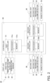
- FIG. 2 is a block diagram for describing the configuration of the controller 50.
- the controller 50 in FIG. 2 includes the first controller 51 and the plurality of second controllers 52.
- the first controller 51 and the plurality of second controllers 52 are connected to each other.
- the first controller 51 includes a processor 51a and a memory 51b.
- the processor 51a reads an air volume control program for the first fan 21 stored in the memory 51b, and outputs necessary commands to the first fan 21 and each second controller 52.
- the memory 51b stores detected values of the first air volume detector 23 and the temperature sensor 24 as needed in addition to the air volume control program for the first fan 21.
- the processor 51a reads the detected values of the first air volume detector 23 and the temperature sensor 24 stored in the memory 51b, and calculates an air volume target value for the first fan 21 (a total of target air volume to be supplied to the target space 100).
- Each second controller 52 includes a processor 52a and a memory 52b.
- the processor 52a reads an air volume control program for the second fan 31 stored in the memory 52b, and outputs necessary commands to the second fan 31.
- the memory 52b stores the air volume target value output from the first controller 51 and a detected value of the second air volume detector 32 as needed in addition to the air volume control program for the second fan 31.
- the processor 52a reads the air volume target value and the detected value of the second air volume detector 32 stored in the memory 52b, and calculates a rotation speed target value of the second fan 31.
- Each second controller 52 receives a temperature measurement value of the target space 100 from a corresponding one of the remote sensors 70 connected thereto. Each second controller 52 holds data indicating a set temperature as a temperature set value.
- Each second controller 52 transmits the temperature set value and the temperature measurement value to the first controller 51.
- the first controller 51 determines an air volume target value for each second unit 30 on the basis of the temperature set value and the temperature measurement value.
- the first controller 51 transmits the value of the air volume target value to each second controller 52.
- the first controller 51 determines the air volume target value for the first fan 21 according to the total of the target air volume to be supplied to the target space 100, and transmits the air volume target value to each second controller 52.
- Each second controller 52 adjusts the rotation speed of the second fan 31 in the corresponding second unit 30. The rotation speeds of the plurality of second fans 31 are adjusted independently from each other.
- Each second controller 52 controls the rotation speed of the corresponding second fan 31 so that the supplied air volume matches the air volume target value.
- the plurality of second controllers 52 control the rotation speeds of the plurality of second fans 31 independently from each other. If the volume of air detected by the second air volume detector 32 is small compared to the air volume target value, each second controller 52 increases the rotation speed of the corresponding second fan 31. If the volume of air detected by the second air volume detector 32 is large compared to the air volume target value, each second controller 52 reduces the rotation speed of the corresponding second fan 31.
- the length of the duct 40 connecting the first unit 20 and the second units 30 varies depending on the positions of the blow-out ports of the second units 30, and also varies depending on a property in which the first unit 20 and the second units 30 are installed.
- duct resistance resistance between the air flowing through the duct 40 and the inner surface of the duct 40, and the static pressure of the air flowing through the duct 40 is reduced by friction.
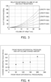
- FIG. 3 is a graph indicating a relation between a volume of air and the duct resistance using the duct length as a parameter.
- the duct resistance changes nonlinearly with respect to the volume of air flowing through the duct 40. Accordingly, the volume of air is not proportional to the rotation speed of the fan. Therefore, the rotation speed for achieving the value of the target air volume cannot be calculated proportionally.
- the difference between the static pressure at the blow-out port and the static pressure at the intake port of the second unit 30 is referred to as front-rear differential pressure of the second unit 30.
- FIG. 4 is a graph indicating results of measuring an air volume change amount when the rotation speed of the fan motor 31b is changed by 1 (r/m) while changing the front-rear differential pressure of the second unit 30.
- the rotation speed of the fan motor 31b before the change is 100 (r/m).
- the required rotation speed change amount of the fan motor 31b varies even with the same air volume change amount as long as the duct resistance is different. This is because the duct resistance also changes depending on the change in volume of air. Therefore, an air volume adjustment function considering a change in duct resistance is required.
- the front-rear differential pressure of one second unit 30 is affected by a change in volume of air of the other second unit 30 and air discharge pressure of the first unit 20.
- the second unit 30 requires also an air volume maintaining function considering a change in front-rear differential pressure.
- the air volume control for one second unit 30 requires the air volume maintaining function considering the duct resistance, the volume of air of the other second unit 30, and the air discharge pressure of the first unit 20.
- the duct length varies depending on the property in which the first unit 20 and the second units 30 are installed or the installation position of the second units 30, and the duct resistance also fluctuates depending on the duct length and the volume of air flowing through the duct. Therefore, it is difficult to convert the relation between the rotation speed and the volume of air of the fan motor 3 1b into data by conventional trial run adjustment.
- the applicant focuses attention on the fact that the change in duct resistance appears as front-rear differential pressure, and has found that the rotation speed target value for the fan motor 3 1b or the rotation speed change amount of the fan motor 31b is calculated by a function using a variable obtained by acquiring information about the volume of air, a wind speed, or the front-rear differential pressure of the second unit 30, in addition to the rotation speed and the value of the target air volume of the fan motor 31b.
- FIG. 7 is a graph indicating a relation between a wind speed V and a rotation speed N of the fan motor 31b using front-rear differential pressure ⁇ P as a parameter.
- the rotation speed N of the fan motor 31b can be expressed by a linear expression of the wind speed V by using a coefficient a and a constant term b.
- N a ⁇ V + b
- the equation (1) can be derived by performing a test for obtaining values of at least three points.
- FIG. 8 is a graph indicating a relation between the front-rear differential pressure ⁇ P and the coefficient a and the constant term b derived from FIG. 7 .
- N m ⁇ ⁇ P + n ⁇ V + p ⁇ ⁇ P + q
- the equation (5) means that the front-rear differential pressure ⁇ P can be calculated by measuring the wind speed V when the fan motor 31b of the second fan 31 operates at the rotation speed N.
- the rotation speed N of the fan motor 31b, the wind speed V or volume of air Q of the second fan 31, and the front-rear differential pressure ⁇ P are parameters having a relation in which, from two values of them, the remaining one value is derived.
- a equation for calculating a rotation speed target value Ny can be derived from the above equation (5) and a theoretical formula of the fan.
- the relation among current front-rear differential pressure ⁇ Px, a current volume of air Qx, a front-rear differential pressure target value ⁇ Py, and an air volume target value Qy is expressed by an equation below from the theoretical formula of the fan.
- ⁇ Py / ⁇ Px Qy / Qx 2
- equation (8) is referred to as a first function.
- FIG. 9 is a graph indicating a relation between the volume of air and the rotation speed of the fan motor 31b using the front-rear differential pressure ⁇ P as a parameter.
- the change in duct resistance appears as a change in front-rear differential pressure ⁇ P.
- the rotation speed of the fan motor 31b for maintaining the volume of air 10 (m 3 /min) at the front-rear differential pressure 50 (Pa) is 920 (r/m). If the duct resistance is constant irrespective of the volume of air, when the volume of air is changed to 15 (m 3 /min), the rotation speed may be simply set to 1100 (r/m).
- the duct resistance changes by changing the volume of air.
- the front-rear differential pressure increases to 109.9 (Pa) due to the change in duct resistance.
- the rotation speed of the fan motor 31b it is necessary to maintain the rotation speed of the fan motor 31b at 1348 (r/m).
- the air volume adjustment function considering the change in duct resistance is required, and the rotation speed Ny in the first function (the above equation (8)) is the rotation speed considering the change in duct resistance.
- the second controller 52 calculates the rotation speed target value for the fan motor 3 1b of the second fan 31 by using the first function.
- the rotation speed of the fan motor 31b reaches the rotation speed target value, the rotation speed is maintained. However, when the volume of air of the other second unit 30 or the air discharge pressure of the first unit 20 is changed, the front-rear differential pressure ⁇ P fluctuates.
- FIG. 10 is a graph indicating a relation between the wind speed and the rotation speed of the fan motor 31b.
- the rotation speed of the fan motor 31b necessary to maintain the wind speed target value Vy at the front-rear differential pressure 50 (Pa) is 980 (r/m).
- the rotation speed change amount ⁇ N of the fan motor 31b is expressed by the following equation from the equations (2) and (4).
- ⁇ N a ⁇ Vy ⁇ Vx
- equation (9) is referred to as a second function.
- the second function is used when calculating the rotation speed change amount when the air volume target value Qy is not changed but the rotation speed of the fan motor 31b needs to be changed due to the fluctuation of the front-rear differential pressure ⁇ P.
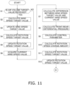
- FIG. 11 is a flowchart of air volume control. The air volume control will be described below with reference to FIG. 11 .
- step S1 the second controller 52 determines whether or not the air volume target value Qy is received from the first controller 51.
- the process proceeds to step S2.
- the process proceeds to step S6.
- step S2 the second controller 52 calculates the wind speed target value Vy for achieving the air volume target value Qy.
- step S3 the second controller 52 updates the wind speed target value Vy to the value calculated in step S2.
- step S4 the second controller 52 calculates the rotation speed target value Ny for the fan motor 31b for achieving the wind speed target value Vy updated in step S3 using the first function.
- step S5 the second controller 52 updates the rotation speed target value for the fan motor 31b to the value Ny calculated in step S4. After updating the rotation speed target value to Ny, the second controller 52 controls the rotation speed of the fan motor 3 1b to reach the target value.
- step S6 the second controller 52 acquires a detected value of the second air volume detector 32 as the current wind speed value Vx.
- step S7 the second controller 52 calculates the difference between the wind speed target value Vy and the current wind speed value Vx.
- step S8 the second controller 52 calculates the front-rear differential pressure ⁇ P.
- step S9 the second controller 52 calculates a coefficient a as a control parameter.
- step S10 the second controller 52 calculates the rotation speed change amount ⁇ N by applying the difference between the wind speed target value Vy and the current wind speed value Vx calculated in step S7 and the coefficient a calculated in step S9 to the second function.
- step S11 the second controller 52 calculates the rotation speed target value Ny on the basis of the rotation speed change amount ⁇ N calculated in step S10.
- step S12 the second controller 52 updates the rotation speed to the rotation speed target value Ny calculated in step S11. Then, the process by the second controller 52 returns to step S1.
- a first program from step S1 to step S5 is executed, but when there is no instruction of the air volume target value from the first controller 51, a second program from step S6 to step S12 is executed.
- the first program is for calculating the rotation speed target value by using the first function
- the second program is for calculating the rotation speed change amount by using the second function.
- the rotation speed target value Ny can also be calculated by using the second function, and the second controller 52 can switch between the first program and the second program. Therefore, even when the second unit 30 acquires a new air volume target value Qy or a new wind speed target value Vy, the second unit 30 can control the rotation speed while calculating the rotation speed change amount ⁇ N by using the second function without using the first function.
- the "front-rear differential pressure ( ⁇ P)" which has not been conventionally taken into consideration, is introduced as a variable into the calculation of the rotation speed target value.
- ⁇ P front-rear differential pressure
- the first function and the second function use, as variables, the rotation speed Nx of the fan motor 31b of the second fan 31, the volume of air Qx or the wind speed Vx of the second fan 31, the front-rear differential pressure ⁇ P, and the air volume target value Qy or the wind speed target value Vy for the second fan 31.
- the rotation speed of the fan motor 31b, the volume of air or the wind speed of the fan, and the front-rear differential pressure are parameters having relation in which, from two values of them, the remaining one value is derived.
- the first function and the second function enable calculation of the rotation speed target value Ny or the rotation speed change amount ⁇ N, which reduces the number of man-hours for a preliminary test, and eliminates the need for a trial run at the time of duct connection.
- the coefficient and the constant can be calculated for each front-rear differential pressure on the basis of the calculation formula obtained from a result of a wind speed measurement test performed while changing the rotation speed of the fan motor 31b in advance.
- the second controller 52 performs control such that the greater the front-rear differential pressure ⁇ P, the smaller the rotation speed change amount of the fan motor 31b per unit volume of air.
- the second controller 52 can switch between the first program for calculating the rotation speed target value Ny for the fan motor 31b by using the first function and the second program for calculating the rotation speed change amount ⁇ N of the fan motor 31b by using the second function. Furthermore, when acquiring a new air volume target value Qy or a new wind speed target value Vy, the second unit 30 may use either the first function or the second function.
- the second controller 52 executes the first program to calculate the rotation speed target value Ny for the fan motor 31b. Furthermore, after acquiring the air volume target value Qy or the wind speed target value Vy from the first controller 51, the second controller 52 switches to the second program to calculate the rotation speed change amount ⁇ N of the fan motor 31b by the second function until the next acquisition of the air volume target value Qy or the wind speed target value Vy.
- the first unit 20 includes the first fan 21 in the above embodiment, but the first unit 20 does not necessarily need the first fan 21.
- the air volume control according to the present disclosure is also applicable to a second unit connected to a first unit not including a fan through a duct.
- FIG. 12 is a configuration diagram of an air supply system 110 equipped with fan units according to a first modification.
- the air supply system 110 in FIG. 12 is disposed behind a ceiling of a floor of a building BL, and ventilates a room.
- the air supply system 110 includes a first unit 120 as an air treatment unit, second units 130 as air supply fan units, and third units 135 as air exhaust fan units.
- the air supply system 110 further includes an outdoor air duct 150, a supply air duct 160, a return air duct 170, and an exhaust air duct 180.
- the outdoor air duct 150, the supply air duct 160, the return air duct 170, and the exhaust air duct 180 are connected to the first unit 120.
- the outdoor air duct 150 constitutes an air flow path leading from an opening 104 leading to the outside of the building BL to the first unit 120.
- the supply air duct 160 constitutes an air flow path leading from the first unit 120 to blow-out ports 102 provided in the room.
- the return air duct 170 constitutes an air flow path leading from intake ports 103 provided in the room to the first unit 120.
- the exhaust air duct 180 constitutes an air flow path leading from the first unit 120 to an opening 105 leading to the outside of the building BL.
- the supply air duct 160 includes a single main duct 161 and a plurality of branch ducts 162 branched off the main duct 161 via a branch chamber 191.
- the return air duct 170 includes a single main duct 171 and a plurality of branch ducts 172 branched off the main duct 171 via a branch chamber 192.
- the first unit 120 removes dust in air passing through the unit, changes temperature of the air, changes humidity of the air, and removes predetermined chemical composition and a predetermined pathogen in the air.
- the second units 130 are connected to the supply air duct 160.
- the third units 135 are connected to each corresponding return air duct 170.
- the first unit 120 does not include any fans, so that the second units 130 and the third units 135 generate a flow of air in the first unit 120.
- a change in front-rear differential pressure of one second unit 130 is mainly caused by changes in volume of air of fans of the other second units 130. Furthermore, a change in front-rear differential pressure of one third unit 135 is mainly caused by a change in volume of air of a fan of the other third unit 135.
- the "front-rear differential pressure" is introduced as a variable of the calculation formula for the rotation speed target value similarly to the above embodiment. Accordingly, it is possible to reflect the change in duct resistance that changes from moment to moment in the calculation of the air volume target value, and to shorten the response time of the output value (volume of air) to the input value (rotation speed).
- FIG. 13 is a configuration diagram of an air supply system 210 equipped with fan units according to a second modification.
- the air supply system 210 in FIG. 13 is disposed behind a ceiling of a floor of a building.
- the air supply system 210 differs from the air supply system 10 in FIG. 1 in that the first unit does not include a first fan, and other configurations are the same as those of the air supply system 10 in FIG. 1 . Therefore, components same as those of the air supply system 10 in FIG. 1 will be denoted by the same reference signs and description thereof is omitted.
- a utilization-side heat exchanger 22 of a first unit 220 is supplied with heat energy required for heat exchange from the heat source unit 60.
- the first unit 220 generates conditioned air through heat exchange in the utilization-side heat exchanger 22.
- the first unit 220 is connected to the duct 40.
- the duct 40 includes the main pipe 41 and the branch pipes 42.
- the main pipe 41 has one end connected to the first unit 220.
- the main pipe 41 has the other end branched and connected to a plurality of branch pipes 42.
- Each branch pipe 42 has a terminal end connected to one second unit 30.
- Each second unit 30 includes a second fan 31.
- the second fan 31 rotates to suck the conditioned air generated in the first unit 20 into the second unit 30 through the duct 40, and then supplies the conditioned air to the target space 100.
- a fan motor 31a of each second fan 31 is configured to change the rotation speed individually.
- Each fan motor 31a changes the rotation speed individually to change the supply air volume of the corresponding second unit 30 individually.
- the first unit 220 does not include any fans, so that the second units 30 generate a flow of air in the first unit 220.
- the change in front-rear differential pressure of one second unit 30 is mainly caused by a change in volume of air of the second fan 31 of the other second unit 30.
- the "front-rear differential pressure" is introduced as a variable of the calculation formula for the rotation speed target value, it is possible to reflect the change in duct resistance that changes from moment to moment in the calculation of the air volume target value, and to shorten the response time of the output value (volume of air) to the input value (rotation speed).
- the front-rear differential pressure is calculated on the basis of the value of the wind speed or the volume of air acquired from the second air volume detector 32.
- the front-rear differential pressure value may be calculated from sensor values of a pressure sensor disposed at each of the intake port and the blow-out port of the second unit, and the wind speed value may be obtained from the front-rear differential pressure and the rotation speed.
- Patent Literature 1 JP H10-253132 A
Landscapes
- Engineering & Computer Science (AREA)
- Mechanical Engineering (AREA)
- General Engineering & Computer Science (AREA)
- Physics & Mathematics (AREA)
- Signal Processing (AREA)
- Chemical & Material Sciences (AREA)
- Combustion & Propulsion (AREA)
- Fluid Mechanics (AREA)
- Fuzzy Systems (AREA)
- Mathematical Physics (AREA)
- Automation & Control Theory (AREA)
- General Physics & Mathematics (AREA)
- Air Conditioning Control Device (AREA)
- Control Of Positive-Displacement Pumps (AREA)
Abstract
Description
- The present disclosure relates to a fan unit including a fan that sends heat-exchanged air.
- Conventionally, an air conditioning system that controls a rotation speed of a fan for conditioning air in a room has been widely used. For example, Patent Literature 1 (
JP H10-253132 A - In such an air conditioning system described above, when a current value is controlled in a conventional manner in order to determine the rotation speed for achieving an air volume target value, the number of man-hours for a preliminary test increases, and it is necessary to adjust the static pressure while performing a trial run at the time of duct connection.
- There is accordingly an issueof reducing the number of man-hours for a preliminary test and eliminating the need for a trial run at the time of duct connection.
- A fan unit according to a first aspect is a fan unit connected to a first unit through a duct, and includes a fan, a casing, a first acquisition unit, a second acquisition unit, a third acquisition unit, and a control unit. The fan supplies air to a target space. The casing has an intake port and a blow-out port and houses the fan. The first acquisition unit acquires the rotation speed of a fan motor that drives the fan. The second acquisition unit acquires information about at least one from among a volume of air, a wind speed, and front-rear differential pressure of the fan. The front-rear differential pressure is a difference in air pressure between the intake port and the blow-out port of the casing. The third acquisition unit acquires an air volume target value or a wind speed target value for the fan. The control unit controls the rotation speed of the fan motor to a rotation speed target value corresponding to the air volume target value or the wind speed target value for the fan. The control unit uses a first function or a second function that uses, as variables: the rotation speed of the fan motor; the volume of air, the wind speed, or the front-rear differential pressure of the fan; and the air volume target value or the wind speed target value for the fan, calculates the rotation speed target value for the fan motor by the first function, and calculates a rotation speed change amount from the rotation speed to the rotation speed target value for the fan motor by the second function.
- In the fan unit, the "front-rear differential pressure (ΔP)", which has not been conventionally taken into consideration, is introduced as a variable into the calculation of the rotation speed target value. As a result, a required volume of air can be more accurately achieved than in the conventional control.
- A fan unit according to a second aspect is the fan unit according to the first aspect, and the first function and the second function use, as variables, the rotation speed of the fan motor, the volume of air or the wind speed of the fan, the front-rear differential pressure, and the air volume target value or the wind speed target value for the fan. The rotation speed of the fan motor, the volume of air or the wind speed of the fan, and the front-rear differential pressure are parameters having a relation in which, from two values of them, the remaining one value is derived.
- When a current value is controlled in a conventional manner in order to determine the rotation speed for achieving the value of the target air volume, the number of man-hours for a preliminary test increases, and moreover, it is necessary to adjust the static pressure while performing a trial run at the time of duct connection.
- In particular, when an attempt is made to realize the air volume control in consideration of the change in duct resistance, since the duct resistance changes along with the change in wind speed even if the duct length is constant, it is extremely difficult to measure a correlation between the rotation speed of the fan motor and the duct resistance in advance.
- On the other hand, the change in duct resistance appears as a change in static pressure in front of and behind the fan. Therefore, the change in duct resistance can be substituted by the change in front-rear differential pressure. It has been confirmed by experiments by the applicant that the correlation between the rotation speed of the fan motor and the front-rear differential pressure can be relatively easily measured by using a wind speed sensor.
- In the fan unit, the rotation speed target value or the rotation speed change amount can be calculated by a predetermined function using variables obtained by acquiring information about the volume of air, the wind speed, or the front-rear differential pressure, in addition to the rotation speed and the value of the target air volume. As a result, the number of man-hours for a preliminary test is reduced, and the need for a trial run at the time of duct connection is eliminated.
- Furthermore, the "front-rear differential pressure" is introduced as a variable of the calculation formula for the rotation speed target value. Accordingly, it is possible to reflect the change in duct resistance that changes from moment to moment in the calculation of the air volume target value, and to shorten the response time of the output value (volume of air) to the input value (rotation speed).
- A fan unit according to a third aspect is the fan unit according to the second aspect, and the first function and the second function are determined on the basis of data of the volume of air or the wind speed of the fan when the rotation speed of the fan motor is changed with respect to the front-rear differential pressure.
- When the front-rear differential pressure is the same, the rotation speed N of the fan motor can be expressed by a linear expression (N = a × V + b) of the wind speed V of the fan. Therefore, a correlation between the rotation speed N and the wind speed V can be acquired in advance by using a wind speed sensor using the front-rear differential pressure as a parameter. It can be understood that a coefficient a and a constant term b with respect to the front-rear differential pressure are linear by plotting the coefficient a and the constant term b for each front-rear differential pressure on the basis of the correlation between the acquired rotation speed N and wind speed V.
- Accordingly, in the fan unit, the coefficient and the constant term can be calculated for each front-rear differential pressure on the basis of the calculation formula obtained from a result of a wind speed measurement test performed while changing the rotation speed of the fan motor in advance.
- A fan unit according to a fourth aspect is the fan unit according to any one of the first to third aspects, and the control unit performs control such that the greater the front-rear differential pressure, the smaller the rotation speed change amount of the fan motor per unit volume of air.
- A fan unit according to a fifth aspect is the fan unit according to any one of the first to fourth aspects, and the control unit can switch between a first program and a second program. The first program calculates the rotation speed target value for the fan motor by using the first function. The second program calculates the rotation speed change amount of the fan motor by using the second function.
- The fan unit uses the first program to calculate the rotation speed target value for the fan motor and the second program to calculate the rotation speed change amount of the fan motor. However, since the first program and the second program can be switched, when acquiring a new air volume target value or a new wind speed target value, the fan unit may use either the first function or the second function. For example, when acquiring a new air volume target value or a new wind speed target value, the fan unit can control the rotation speed while calculating the rotation speed change amount by using the second function without using the first function.
- A fan unit according to a sixth aspect is the fan unit according to the fifth aspect, and the third acquisition unit acquires the air volume target value or the wind speed target value a plurality of times. The control unit executes the first program to calculate the rotation speed target value for the fan motor when the third acquisition unit acquires the air volume target value or the wind speed target value. Furthermore, the control unit switches, after the third acquisition unit acquires the air volume target value or the wind speed target value, to the second program to calculate the rotation speed change amount of the fan motor by the second function until the next acquisition of the air volume target value or the wind speed target value.
- For example, in a case where the control unit is configured to acquire the air volume target value at predetermined time intervals irrespective of whether or not there is an instruction of the air volume target value, the control unit may switch to the second program to calculate the rotation speed change amount of the fan motor by the second function until the next acquisition of the air volume target value.
-
-
FIG. 1 is a conceptual diagram illustrating the configuration of an air supply system equipped with fan units according to an embodiment of the present disclosure. -
FIG. 2 is a block diagram for describing the configuration of a controller. -
FIG. 3 is a graph indicating a relation between a volume of air and duct resistance using duct length as a parameter. -
FIG. 4 is a graph indicating results of measuring an air volume change amount when a rotation speed of a fan motor is changed by 1 (r/m) while changing front-rear differential pressure of a second unit. -
FIG. 5 is a graph indicating a relation between the volume of air and the rotation speed of the fan motor using the front-rear differential pressure as a parameter. -
FIG. 6 is a graph indicating a relation between the volume of air and the rotation speed of the fan motor using the front-rear differential pressure as a parameter. -
FIG. 7 is a graph indicating a relation between a wind speed and the rotation speed of the fan motor using the front-rear differential pressure as a parameter. -
FIG. 8 is a graph indicating a relation between the front-rear differential pressure and a coefficient and a constant term derived fromFIG. 7 . -
FIG. 9 is a graph indicating a relation between the volume of air and the rotation speed of the fan motor using the front-rear differential pressure as a parameter. -
FIG. 10 is a graph indicating a relation between the wind speed and the rotation speed of the fan motor. -
FIG. 11 is a flowchart of air volume control. -
FIG. 12 is a configuration diagram of an air supply system equipped with fan units according to a first modification. -
FIG. 13 is a configuration diagram of an air supply system equipped with fan units according to a second modification. -
FIG. 1 is a configuration diagram of anair supply system 10 equipped with fan units according to an embodiment of the present disclosure. Theair supply system 10 inFIG. 1 includes afirst unit 20, a plurality ofsecond units 30, aduct 40, and acontroller 50. In the present application, for convenience of description, the fan units are referred to as the second units. - The
first unit 20 includes afirst fan 21. Eachsecond unit 30 includes asecond fan 31. Eachsecond fan 31 supplies air from thesecond unit 30 to atarget space 100. - The
target space 100 is, for example, a room in a building. The room is a space where the movement of air is restricted by a floor, a ceiling, and walls, for example. The plurality ofsecond units 30 are installed with respect to one or a plurality oftarget spaces 100. - In
FIG. 1 , theair supply system 10 including twosecond units 30 installed with respect to onetarget space 100 is illustrated as a typical example of theair supply system 10 including a plurality ofsecond units 30. - For example, the number of
second units 30 may also be three or more, and is set appropriately. For example, the number oftarget spaces 100 in which thesecond units 30 are installed may be two or more. - The
duct 40 distributes first air SA delivered from thefirst unit 20 by thefirst fan 21 to the plurality ofsecond units 30. Theduct 40 includes amain pipe 41 andbranch pipes 42 branched off themain pipe 41. -
FIG. 1 illustrates a case where themain pipe 41 is disposed outside thefirst unit 20, but themain pipe 41 may also be disposed inside thefirst unit 20, and may also be disposed to extend from the inside of thefirst unit 20 to the outside of thefirst unit 20. - The case where the
main pipe 41 is disposed inside thefirst unit 20 also includes a case where a portion of acasing 26 of thefirst unit 20 functions as themain pipe 41.FIG. 1 illustrates an example in which themain pipe 41 has aninlet 41a connected to thefirst unit 20. - The
first fan 21 is disposed inside thefirst unit 20. Here, it is configured that all of the air blown out from thefirst fan 21 flows into theduct 40. - The
main pipe 41 of theduct 40 also has anoutlet 41b connected toinlets 42a of thebranch pipes 42. For example, the configuration for branching themain pipe 41 into thebranch pipes 42 may be a configuration using a branch chamber. - Each
second unit 30 includes acasing 33 having anintake port 33a and a blow-outport 33b. Thebranch pipes 42 have a plurality ofoutlets 42b connected tointake ports 33a of the plurality ofsecond units 30. - Each
second unit 30 is connected to thetarget space 100 through aventilation path 81. Theventilation path 81 has aninlet 81a connected to the blow-outport 33b of thesecond unit 30. Eachsecond fan 31 produces an air flow from theoutlet 42b of theduct 40 toward theinlet 81a of theventilation path 81, inside thesecond unit 30. Therefore, eachsecond fan 31 is suctioning the first air SA from theoutlet 42b of thebranch pipe 42. - Each
second fan 31 can change front-rear differential pressure that is a difference in air pressure between theintake port 33a and the blow-outport 33b of the correspondingsecond unit 30 by changing a rotation speed of a motor. Assuming that the static pressure in theduct 40 is constant, eachsecond fan 31 can increase the front-rear differential pressure in the correspondingsecond unit 30 by increasing the rotation speed. - If the front-rear differential pressure in the
second unit 30 increases, the volume of the first air SA flowing through theventilation path 81 increases. This change in volume of flowing air changes the supplied air volume that is blown out from anoutlet 81b of eachventilation path 81 into thetarget space 100. - The
controller 50 includes afirst controller 51 and a plurality ofsecond controllers 52. Thefirst controller 51 and the plurality ofsecond controllers 52 are connected to each other. - The
first controller 51 controls the rotation speed of thefirst fan 21. If the rotation speed of thefirst fan 21 increases, a volume of air sent by thefirst fan 21 increases. - One
second controller 52 is provided with respect to eachsecond unit 30. Eachsecond controller 52 controls a volume of air of the correspondingsecond fan 31. Eachsecond controller 52 stores an air volume target value received from thefirst controller 51. - If the supplied air volume is insufficient with respect to the air volume target value, each
second controller 52 increases the rotation speed of thesecond fan 31. Conversely, if the supplied air volume is excessive with respect to the air volume target value, thesecond controller 52 reduces the rotation speed of thesecond fan 31. - The
controller 50 obtains information about the volume of air supplied to thetarget space 100 by a plurality of thesecond fans 31. The information about the volume of air includes, for example, a necessary volume of air to be supplied into thetarget space 100 per second or per minute. - Each
second controller 52 outputs the information about the volume of air to thefirst controller 51. Thefirst controller 51 determines the output required from thefirst fan 21 on the basis of the obtained information about the volume of air. - The
first unit 20 includes thefirst fan 21, aheat exchanger 22, a firstair volume detector 23, atemperature sensor 24, and a watervolume adjustment valve 25. - The
heat exchanger 22 is supplied with, for example, cold water or hot water as a heat medium from aheat source unit 60. For example, the heat medium supplied to theheat exchanger 22 may be something other than cold water or hot water, such as brine. - Examples of the first
air volume detector 23 include an air volume sensor, a wind speed sensor, or a differential pressure sensor. In the embodiment, the firstair volume detector 23 detects a volume of air sent by thefirst fan 21. - The first
air volume detector 23 is connected to thefirst controller 51. The firstair volume detector 23 transmits the value of the volume of air detected by the firstair volume detector 23 to thefirst controller 51. - The volume of air detected by the first
air volume detector 23 is the volume of air flowing through themain pipe 41 of theduct 40, and is also a total volume of air supplied from the plurality ofsecond units 30 to thetarget space 100. - The
temperature sensor 24 detects the temperature of the first air SA sent from thefirst fan 21 to theduct 40. Thetemperature sensor 24 is connected to thefirst controller 51. Thetemperature sensor 24 inputs the detected value to thefirst controller 51. - The
first unit 20 is connected to thetarget space 100 through aventilation path 82. Second air RA passing through theventilation path 82 and returning from thetarget space 100 is sent out by thefirst fan 21 to theduct 40 through theheat exchanger 22. - The second air RA returning from the
target space 100 is the air that existed inside thetarget space 100. When passing through theheat exchanger 22, the returning second air RA exchanges heat with the cold water or the hot water flowing through theheat exchanger 22 to become conditioned air. - The water
volume adjustment valve 25 adjusts the amount of heat imparted to the first air SA that exchanges heat in theheat exchanger 22 and is sent out to theduct 40. An opening degree of the watervolume adjustment valve 25 is controlled by thefirst controller 51. If the opening degree of the watervolume adjustment valve 25 is increased, the volume of water flowing through theheat exchanger 22 increases, so that the amount of heat to be exchanged between theheat exchanger 22 and the first air SA per unit time increases. Conversely, if the opening degree of the watervolume adjustment valve 25 is decreased, the volume of water flowing through theheat exchanger 22 decreases, so that the amount of heat to be exchanged between theheat exchanger 22 and the first air SA per unit time decreases. - The
second unit 30 includes thesecond fan 31, afan motor 31b that rotates thesecond fan 31, and a secondair volume detector 32. - Each
fan motor 31b is connected to a corresponding one of thesecond controllers 52, and sends the rotation speed to thesecond controller 52. Each secondair volume detector 32 is connected to a corresponding one of thesecond controllers 52. - Examples of the second
air volume detector 32 include an air volume sensor, a wind speed sensor, or a differential pressure sensor. In the embodiment, the secondair volume detector 32 detects a volume of air sent by thesecond fan 31. - The second
air volume detector 32 inputs the detected value of the volume of air to thesecond controller 52. The volume of air detected by the secondair volume detector 32 is the volume of air flowing through theventilation path 81, and is also the volume of air supplied from eachsecond unit 30 to thetarget space 100. - A plurality of
remote sensors 70 function as temperature sensors. Eachremote sensor 70 is configured to transmit data indicating the temperature of the second air RAin thetarget space 100 to a correspondingsecond controller 52. -
FIG. 2 is a block diagram for describing the configuration of thecontroller 50. Thecontroller 50 inFIG. 2 includes thefirst controller 51 and the plurality ofsecond controllers 52. Thefirst controller 51 and the plurality ofsecond controllers 52 are connected to each other. - The
first controller 51 includes aprocessor 51a and amemory 51b. Theprocessor 51a reads an air volume control program for thefirst fan 21 stored in thememory 51b, and outputs necessary commands to thefirst fan 21 and eachsecond controller 52. - The
memory 51b stores detected values of the firstair volume detector 23 and thetemperature sensor 24 as needed in addition to the air volume control program for thefirst fan 21. - The
processor 51a reads the detected values of the firstair volume detector 23 and thetemperature sensor 24 stored in thememory 51b, and calculates an air volume target value for the first fan 21 (a total of target air volume to be supplied to the target space 100). - The above description is an example and the present disclosure is not limited to the above content of description.
- Each
second controller 52 includes aprocessor 52a and amemory 52b. Theprocessor 52a reads an air volume control program for thesecond fan 31 stored in thememory 52b, and outputs necessary commands to thesecond fan 31. - The
memory 52b stores the air volume target value output from thefirst controller 51 and a detected value of the secondair volume detector 32 as needed in addition to the air volume control program for thesecond fan 31. - The
processor 52a reads the air volume target value and the detected value of the secondair volume detector 32 stored in thememory 52b, and calculates a rotation speed target value of thesecond fan 31. - The above description is an example and the present invention is not limited to the above content of description.
- Each
second controller 52 receives a temperature measurement value of thetarget space 100 from a corresponding one of theremote sensors 70 connected thereto. Eachsecond controller 52 holds data indicating a set temperature as a temperature set value. - Each
second controller 52 transmits the temperature set value and the temperature measurement value to thefirst controller 51. Thefirst controller 51 determines an air volume target value for eachsecond unit 30 on the basis of the temperature set value and the temperature measurement value. Thefirst controller 51 transmits the value of the air volume target value to eachsecond controller 52. - The
first controller 51 determines the air volume target value for thefirst fan 21 according to the total of the target air volume to be supplied to thetarget space 100, and transmits the air volume target value to eachsecond controller 52. Eachsecond controller 52 adjusts the rotation speed of thesecond fan 31 in the correspondingsecond unit 30. The rotation speeds of the plurality ofsecond fans 31 are adjusted independently from each other. - Each
second controller 52 controls the rotation speed of the correspondingsecond fan 31 so that the supplied air volume matches the air volume target value. The plurality ofsecond controllers 52 control the rotation speeds of the plurality ofsecond fans 31 independently from each other. If the volume of air detected by the secondair volume detector 32 is small compared to the air volume target value, eachsecond controller 52 increases the rotation speed of the correspondingsecond fan 31. If the volume of air detected by the secondair volume detector 32 is large compared to the air volume target value, eachsecond controller 52 reduces the rotation speed of the correspondingsecond fan 31. - Specific air volume control will be described in the section of "(5) Air volume control".
- The length of the
duct 40 connecting thefirst unit 20 and thesecond units 30 varies depending on the positions of the blow-out ports of thesecond units 30, and also varies depending on a property in which thefirst unit 20 and thesecond units 30 are installed. - There is resistance (hereinafter, referred to as duct resistance) between the air flowing through the
duct 40 and the inner surface of theduct 40, and the static pressure of the air flowing through theduct 40 is reduced by friction. The longer theduct 40, the larger the duct resistance. -
FIG. 3 is a graph indicating a relation between a volume of air and the duct resistance using the duct length as a parameter. InFIG. 3 , the duct resistance changes nonlinearly with respect to the volume of air flowing through theduct 40. Accordingly, the volume of air is not proportional to the rotation speed of the fan. Therefore, the rotation speed for achieving the value of the target air volume cannot be calculated proportionally. - The difference between the static pressure at the blow-out port and the static pressure at the intake port of the
second unit 30 is referred to as front-rear differential pressure of thesecond unit 30. -
FIG. 4 is a graph indicating results of measuring an air volume change amount when the rotation speed of thefan motor 31b is changed by 1 (r/m) while changing the front-rear differential pressure of thesecond unit 30. The rotation speed of thefan motor 31b before the change is 100 (r/m). - In
FIGS. 3 and 4 , when the volume of air is changed to adjust the temperature, the duct resistance fluctuates, so that the front-rear differential pressure of thesecond unit 30 changes. Since the volume of air that changes when the rotation speed of the fan is changed by 1 (r/m) varies depending on the situation (front-rear differential pressure) at that time, adjustment is difficult. Therefore, the target air volume may not be reached unless the rotation speed of the fan is adjusted in consideration of the change in duct resistance. - For example, as illustrated in
FIG. 5 , even when the volume of air is changed from 10 (m3/min) to 15 (m3/min), the required rotation speed change amount of thefan motor 31b varies even with the same air volume change amount as long as the duct resistance is different. This is because the duct resistance also changes depending on the change in volume of air. Therefore, an air volume adjustment function considering a change in duct resistance is required. - Furthermore, in the case where the
branch pipes 42 branched off themain pipe 41 are connected to the respectivesecond units 30 as illustrated inFIG. 1 , the front-rear differential pressure of onesecond unit 30 is affected by a change in volume of air of the othersecond unit 30 and air discharge pressure of thefirst unit 20. - Furthermore, as illustrated in
FIG. 6 , when the volume of air of the othersecond unit 30 or the air discharge pressure from thefirst unit 20 is changed and the front-rear differential pressure is increased to the dotted line inFIG. 6 , simply maintaining the rotation speed of thefan motor 31b leads to a decrease in the volume of air from 10 (m3/min) to 5 (m3/min). Therefore, the rotation speed of thefan motor 31b needs to be increased in order to maintain the initial volume of air 10 (m3/min). - On the other hand, when the front-rear differential pressure is decreased to a two-dot chain line in
FIG. 6 , maintaining the rotation speed of thefan motor 31b leads to an increase in the volume of air from 10 (m3/min) to 15 (m3/min). Accordingly, the rotation speed of thefan motor 31b needs to be reduced in order to maintain the initial volume of air 10 (m3/min). - Therefore, the
second unit 30 requires also an air volume maintaining function considering a change in front-rear differential pressure. - As described above, it has been found that the air volume control for one
second unit 30 requires the air volume maintaining function considering the duct resistance, the volume of air of the othersecond unit 30, and the air discharge pressure of thefirst unit 20. However, the duct length varies depending on the property in which thefirst unit 20 and thesecond units 30 are installed or the installation position of thesecond units 30, and the duct resistance also fluctuates depending on the duct length and the volume of air flowing through the duct. Therefore, it is difficult to convert the relation between the rotation speed and the volume of air of the fan motor 3 1b into data by conventional trial run adjustment. - In view of the above, the applicant focuses attention on the fact that the change in duct resistance appears as front-rear differential pressure, and has found that the rotation speed target value for the fan motor 3 1b or the rotation speed change amount of the
fan motor 31b is calculated by a function using a variable obtained by acquiring information about the volume of air, a wind speed, or the front-rear differential pressure of thesecond unit 30, in addition to the rotation speed and the value of the target air volume of thefan motor 31b. - This reduces the number of man-hours for a preliminary test, and eliminates the need for a trial run at the time of duct connection. An air volume control logic will be described below.
-
FIG. 7 is a graph indicating a relation between a wind speed V and a rotation speed N of thefan motor 31b using front-rear differential pressure ΔP as a parameter. InFIG. 7 , when the front-rear differential pressure ΔP is the same, the rotation speed N of thefan motor 31b can be expressed by a linear expression of the wind speed V by using a coefficient a and a constant term b.
- As illustrated in
FIG. 7 , when the front-rear differential pressure is constant, the equation (1) can be derived by performing a test for obtaining values of at least three points. - Furthermore,
FIG. 8 is a graph indicating a relation between the front-rear differential pressure ΔP and the coefficient a and the constant term b derived fromFIG. 7 . InFIG. 8 , the relation between the front-rear differential pressure ΔP and the coefficient a and the constant term b can be expressed by the following equations.

- From the above equations (1), (2), and (3), the relation among the rotation speed N, the wind speed V, and the front-rear differential pressure ΔP is expressed by the following equation.

- From the equation (4), the following equation is further derived.

- The equation (5) means that the front-rear differential pressure ΔP can be calculated by measuring the wind speed V when the
fan motor 31b of thesecond fan 31 operates at the rotation speed N. - Therefore, the rotation speed N of the
fan motor 31b, the wind speed V or volume of air Q of thesecond fan 31, and the front-rear differential pressure ΔP are parameters having a relation in which, from two values of them, the remaining one value is derived. - A equation for calculating a rotation speed target value Ny can be derived from the above equation (5) and a theoretical formula of the fan. The relation among current front-rear differential pressure ΔPx, a current volume of air Qx, a front-rear differential pressure target value ΔPy, and an air volume target value Qy is expressed by an equation below from the theoretical formula of the fan.

- From the above equations (5) and (6), the following equation holds.

- Furthermore, since Vy = (Qy/Qx) × Vx, the following equation holds.

- Hereinafter, the equation (8) is referred to as a first function.
- Technical significance of the first function will be described with reference to
FIG. 9. FIG. 9 is a graph indicating a relation between the volume of air and the rotation speed of thefan motor 31b using the front-rear differential pressure ΔP as a parameter. InFIG. 9 , the change in duct resistance appears as a change in front-rear differential pressure ΔP. - For example, the rotation speed of the
fan motor 31b for maintaining the volume of air 10 (m3/min) at the front-rear differential pressure 50 (Pa) is 920 (r/m). If the duct resistance is constant irrespective of the volume of air, when the volume of air is changed to 15 (m3/min), the rotation speed may be simply set to 1100 (r/m). - However, the duct resistance changes by changing the volume of air. According to
FIG. 9 , by changing the volume of air to 15 (m3/min), the front-rear differential pressure increases to 109.9 (Pa) due to the change in duct resistance. In order to maintain the volume of air 15 (m3/min) when the front-rear differential pressure is 109.9 (Pa), it is necessary to maintain the rotation speed of thefan motor 31b at 1348 (r/m). - Therefore, the air volume adjustment function considering the change in duct resistance is required, and the rotation speed Ny in the first function (the above equation (8)) is the rotation speed considering the change in duct resistance.
- When the air volume target value Qy, which is an instruction value of the volume of air from the
first controller 51, is changed, thesecond controller 52 calculates the rotation speed target value for the fan motor 3 1b of thesecond fan 31 by using the first function. - If the front-rear differential pressure ΔP does not fluctuate even after the rotation speed of the
fan motor 31b reaches the rotation speed target value, the rotation speed is maintained. However, when the volume of air of the othersecond unit 30 or the air discharge pressure of thefirst unit 20 is changed, the front-rear differential pressure ΔP fluctuates. -
FIG. 10 is a graph indicating a relation between the wind speed and the rotation speed of thefan motor 31b. InFIG. 10 , for example, the rotation speed of thefan motor 31b necessary to maintain the wind speed target value Vy at the front-rear differential pressure 50 (Pa) is 980 (r/m). - Here, when the front-rear differential pressure ΔP is increased to the dotted line in
FIG. 10 , simply maintaining the rotation speed of thefan motor 31b at 980 (r/m) leads to a decrease in the wind speed to Vx, so that the volume of air becomes insufficient. - In order to maintain the air volume target value, it is necessary to recover the wind speed from Vx to Vy, and it is necessary to increase the rotation speed of the
fan motor 31b by 200 r/m to 1180 (r/m). - The rotation speed change amount ΔN of the
fan motor 31b is expressed by the following equation from the equations (2) and (4).
- Hereinafter, the equation (9) is referred to as a second function.
- The second function is used when calculating the rotation speed change amount when the air volume target value Qy is not changed but the rotation speed of the
fan motor 31b needs to be changed due to the fluctuation of the front-rear differential pressure ΔP. -
FIG. 11 is a flowchart of air volume control. The air volume control will be described below with reference toFIG. 11 . - First, in step S1, the
second controller 52 determines whether or not the air volume target value Qy is received from thefirst controller 51. When thesecond controller 52 receives the air volume target value Qy, the process proceeds to step S2. When thesecond controller 52 does not receive the air volume target value Qy, the process proceeds to step S6. - Next, in step S2, the
second controller 52 calculates the wind speed target value Vy for achieving the air volume target value Qy. - Next, in step S3, the
second controller 52 updates the wind speed target value Vy to the value calculated in step S2. - Next, in step S4, the
second controller 52 calculates the rotation speed target value Ny for thefan motor 31b for achieving the wind speed target value Vy updated in step S3 using the first function. - Next, in step S5, the
second controller 52 updates the rotation speed target value for thefan motor 31b to the value Ny calculated in step S4. After updating the rotation speed target value to Ny, thesecond controller 52 controls the rotation speed of the fan motor 3 1b to reach the target value. - Next, in step S6, the
second controller 52 acquires a detected value of the secondair volume detector 32 as the current wind speed value Vx. - Next, in step S7, the
second controller 52 calculates the difference between the wind speed target value Vy and the current wind speed value Vx. - Next, in step S8, the
second controller 52 calculates the front-rear differential pressure ΔP. - Next, in step S9, the
second controller 52 calculates a coefficient a as a control parameter. - Next, in step S10, the
second controller 52 calculates the rotation speed change amount ΔN by applying the difference between the wind speed target value Vy and the current wind speed value Vx calculated in step S7 and the coefficient a calculated in step S9 to the second function. - Next, in step S11, the
second controller 52 calculates the rotation speed target value Ny on the basis of the rotation speed change amount ΔN calculated in step S10. - Next, in step S12, the
second controller 52 updates the rotation speed to the rotation speed target value Ny calculated in step S11. Then, the process by thesecond controller 52 returns to step S1. - As described above, when there is an instruction of the air volume target value from the
first controller 51, a first program from step S1 to step S5 is executed, but when there is no instruction of the air volume target value from thefirst controller 51, a second program from step S6 to step S12 is executed. - The first program is for calculating the rotation speed target value by using the first function, and the second program is for calculating the rotation speed change amount by using the second function.
- Furthermore, the rotation speed target value Ny can also be calculated by using the second function, and the
second controller 52 can switch between the first program and the second program. Therefore, even when thesecond unit 30 acquires a new air volume target value Qy or a new wind speed target value Vy, thesecond unit 30 can control the rotation speed while calculating the rotation speed change amount ΔN by using the second function without using the first function. - (6-1)
Thesecond controller 52 acquires: a rotation speed Nx of thefan motor 31b of thesecond fan 31; the volume of air Qx, the wind speed Vx, or the front-rear differential pressure ΔPx of thesecond fan 31; and the air volume target value Qy or the wind speed target value Vy for thesecond fan 31, and calculates the rotation speed target value Ny for thefan motor 31b by using the first function: Ny = (Qy/Qx)2 × ΔPx × {m × (Qy/Qx) × Vx + p} + n × (Qy/Qx) × Vx + q. Furthermore, when the front-rear differential pressure ΔP fluctuates and the wind speed is decreased from Vy to Vx, thesecond controller 52 calculates the rotation speed change amount ΔN to the rotation speed target value by using the second function: ΔN = a × (Vy - Vx). - In the fan unit, the "front-rear differential pressure (ΔP)", which has not been conventionally taken into consideration, is introduced as a variable into the calculation of the rotation speed target value. As a result, a required volume of air can be more accurately achieved than in the conventional control.
- (6-2)
The first function and the second function use, as variables, the rotation speed Nx of thefan motor 31b of thesecond fan 31, the volume of air Qx or the wind speed Vx of thesecond fan 31, the front-rear differential pressure ΔP, and the air volume target value Qy or the wind speed target value Vy for thesecond fan 31. The rotation speed of thefan motor 31b, the volume of air or the wind speed of the fan, and the front-rear differential pressure are parameters having relation in which, from two values of them, the remaining one value is derived. - In the
second unit 30, the first function and the second function enable calculation of the rotation speed target value Ny or the rotation speed change amount ΔN, which reduces the number of man-hours for a preliminary test, and eliminates the need for a trial run at the time of duct connection. - (6-3)
When the front-rear differential pressure ΔP is the same, the rotation speed N of the fan motor 3 1b can be expressed by a linear expression (N = a × V + b) of the wind speed V of the fan. Therefore, a correlation between the rotation speed N and the wind speed V can be acquired in advance by using a wind speed sensor using the front-rear differential pressure as a parameter. It can be understood that the coefficient and the constant with respect to the front-rear differential pressure are linear by plotting the coefficient and the constant for each front-rear differential pressure on the basis of the correlation between the acquired rotation speed N and wind speed V. - Accordingly, in the
second unit 30, the coefficient and the constant can be calculated for each front-rear differential pressure on the basis of the calculation formula obtained from a result of a wind speed measurement test performed while changing the rotation speed of thefan motor 31b in advance. - (6-4)
In thesecond unit 30, thesecond controller 52 performs control such that the greater the front-rear differential pressure ΔP, the smaller the rotation speed change amount of thefan motor 31b per unit volume of air. - (6-5)
Thesecond controller 52 can switch between the first program for calculating the rotation speed target value Ny for thefan motor 31b by using the first function and the second program for calculating the rotation speed change amount ΔN of thefan motor 31b by using the second function. Furthermore, when acquiring a new air volume target value Qy or a new wind speed target value Vy, thesecond unit 30 may use either the first function or the second function. - (6-6)
When acquiring the air volume target value Qy or the wind speed target value Vy from thefirst controller 51, thesecond controller 52 executes the first program to calculate the rotation speed target value Ny for thefan motor 31b. Furthermore, after acquiring the air volume target value Qy or the wind speed target value Vy from thefirst controller 51, thesecond controller 52 switches to the second program to calculate the rotation speed change amount ΔN of thefan motor 31b by the second function until the next acquisition of the air volume target value Qy or the wind speed target value Vy. - The
first unit 20 includes thefirst fan 21 in the above embodiment, but thefirst unit 20 does not necessarily need thefirst fan 21. The air volume control according to the present disclosure is also applicable to a second unit connected to a first unit not including a fan through a duct. - Specific examples will be described below.
-
FIG. 12 is a configuration diagram of anair supply system 110 equipped with fan units according to a first modification. Theair supply system 110 inFIG. 12 is disposed behind a ceiling of a floor of a building BL, and ventilates a room. Theair supply system 110 includes afirst unit 120 as an air treatment unit,second units 130 as air supply fan units, andthird units 135 as air exhaust fan units. - The
air supply system 110 further includes anoutdoor air duct 150, asupply air duct 160, areturn air duct 170, and anexhaust air duct 180. Theoutdoor air duct 150, thesupply air duct 160, thereturn air duct 170, and theexhaust air duct 180 are connected to thefirst unit 120. - The
outdoor air duct 150 constitutes an air flow path leading from anopening 104 leading to the outside of the building BL to thefirst unit 120. Thesupply air duct 160 constitutes an air flow path leading from thefirst unit 120 to blow-outports 102 provided in the room. - The
return air duct 170 constitutes an air flow path leading fromintake ports 103 provided in the room to thefirst unit 120. Theexhaust air duct 180 constitutes an air flow path leading from thefirst unit 120 to anopening 105 leading to the outside of the building BL. - The
supply air duct 160 includes a singlemain duct 161 and a plurality ofbranch ducts 162 branched off themain duct 161 via abranch chamber 191. - The
return air duct 170 includes a singlemain duct 171 and a plurality ofbranch ducts 172 branched off themain duct 171 via abranch chamber 192. - The
first unit 120 removes dust in air passing through the unit, changes temperature of the air, changes humidity of the air, and removes predetermined chemical composition and a predetermined pathogen in the air. - The
second units 130 are connected to thesupply air duct 160. Thethird units 135 are connected to each correspondingreturn air duct 170. - In the
air supply system 110, thefirst unit 120 does not include any fans, so that thesecond units 130 and thethird units 135 generate a flow of air in thefirst unit 120. - Therefore, a change in front-rear differential pressure of one
second unit 130 is mainly caused by changes in volume of air of fans of the othersecond units 130. Furthermore, a change in front-rear differential pressure of onethird unit 135 is mainly caused by a change in volume of air of a fan of the otherthird unit 135. - In the first modification, the "front-rear differential pressure" is introduced as a variable of the calculation formula for the rotation speed target value similarly to the above embodiment. Accordingly, it is possible to reflect the change in duct resistance that changes from moment to moment in the calculation of the air volume target value, and to shorten the response time of the output value (volume of air) to the input value (rotation speed).
-
FIG. 13 is a configuration diagram of anair supply system 210 equipped with fan units according to a second modification. Theair supply system 210 inFIG. 13 is disposed behind a ceiling of a floor of a building. - The
air supply system 210 differs from theair supply system 10 inFIG. 1 in that the first unit does not include a first fan, and other configurations are the same as those of theair supply system 10 inFIG. 1 . Therefore, components same as those of theair supply system 10 inFIG. 1 will be denoted by the same reference signs and description thereof is omitted. - A utilization-
side heat exchanger 22 of afirst unit 220 is supplied with heat energy required for heat exchange from theheat source unit 60. Thefirst unit 220 generates conditioned air through heat exchange in the utilization-side heat exchanger 22. - The
first unit 220 is connected to theduct 40. Theduct 40 includes themain pipe 41 and thebranch pipes 42. Themain pipe 41 has one end connected to thefirst unit 220. Themain pipe 41 has the other end branched and connected to a plurality ofbranch pipes 42. Eachbranch pipe 42 has a terminal end connected to onesecond unit 30. - Each
second unit 30 includes asecond fan 31. Thesecond fan 31 rotates to suck the conditioned air generated in thefirst unit 20 into thesecond unit 30 through theduct 40, and then supplies the conditioned air to thetarget space 100. - A fan motor 31a of each
second fan 31 is configured to change the rotation speed individually. Each fan motor 31a changes the rotation speed individually to change the supply air volume of the correspondingsecond unit 30 individually. - In the
air supply system 210, thefirst unit 220 does not include any fans, so that thesecond units 30 generate a flow of air in thefirst unit 220. - Therefore, the change in front-rear differential pressure of one
second unit 30 is mainly caused by a change in volume of air of thesecond fan 31 of the othersecond unit 30. However, since the "front-rear differential pressure" is introduced as a variable of the calculation formula for the rotation speed target value, it is possible to reflect the change in duct resistance that changes from moment to moment in the calculation of the air volume target value, and to shorten the response time of the output value (volume of air) to the input value (rotation speed). - (8-1)
In the above embodiment and modifications, the front-rear differential pressure is calculated on the basis of the value of the wind speed or the volume of air acquired from the secondair volume detector 32. However, the front-rear differential pressure value may be calculated from sensor values of a pressure sensor disposed at each of the intake port and the blow-out port of the second unit, and the wind speed value may be obtained from the front-rear differential pressure and the rotation speed. - (8-2)
InFIG. 7 , changes in wind speed of a fan when the rotation speed of a fan motor is changed are observed at five front-rear differential pressures. This is utilized as data for deriving a relational expression of the rotation speed, the wind speed, and the front-rear differential pressure, but does not necessarily require data for five front-rear differential pressures, and the relational expression can be derived if there is data for at least three front-rear differential pressures. - The embodiment of the present disclosure has been described above. It will be understood that various changes to modes and details can be made without departing from the spirit and scope of the present disclosure recited in the claims.
-
- 20: first unit
- 30: second unit (fan unit)
- 31: second fan (fan)
- 31b: fan motor
- 32: second air volume detector (second acquisition unit)
- 33: casing
- 33a: intake port
- 33b: blow-out port
- 40: duct
- 50: controller (control unit)
- 51: first controller (third acquisition unit)
- 52: second controller (first acquisition unit)
- 120: first unit
- 130: second unit (fan unit)
- 135: third unit (fan unit)
- 160: supply air duct (duct)
- 170: ventilation duct (duct)
- Patent Literature 1:
JP H10-253132 A
Claims (6)
- A fan unit (30) connected to a first unit (20) through a duct (40), the fan unit (30) comprising:a fan (31) that supplies air to a target space;a casing (33) that has an intake port (33a) and a blow-out port (33b) and houses the fan (31);a first acquisition unit that acquires a rotation speed (Nx) of a fan motor (31b) that drives the fan (31);a second acquisition unit (32) that acquires information about at least one from among a volume of air (Qx), a wind speed (Vx), and front-rear differential pressure (ΔPx) that is a difference in air pressure between the intake port and the blow-out port of the casing (33), of the fan (31);a third acquisition unit that acquires an air volume target value (Qy) or a wind speed target value (Vy) for the fan (31); anda control unit (50) that controls the rotation speed (Nx) of the fan motor (31b) to a rotation speed target value (Ny) corresponding to the air volume target value (Qy) or the wind speed target value (Vy) for the fan (31), whereinthe control unit (50) uses a first function or a second function that uses, as variables: the rotation speed (Nx) of the fan motor (31b); the volume of air (Qx), the wind speed (Vx), or the front-rear differential pressure (ΔPx) of the fan (31); and the air volume target value (Qy) or the wind speed target value (Vy) for the fan (31), calculates the rotation speed target value (Ny) for the fan motor (31b) by the first function, and calculates a rotation speed change amount from the rotation speed (Nx) to the rotation speed target value (Ny) for the fan motor (31b) by the second function.
- The fan unit (30) according to claim 1, whereinthe first function and the second function use, as variables, the rotation speed (Nx) of the fan motor (31b), the volume of air (Qx) or the wind speed (Vx) of the fan (31), the front-rear differential pressure (ΔPx), and the air volume target value (Qy) or the wind speed target value (Vy) for the fan (31), andthe rotation speed (Nx) of the fan motor (31b), the volume of air (Qx) or the wind speed (Vx) of the fan (31), and the front-rear differential pressure (ΔPx) are parameters having a relation in which, from two values of them, a remaining one value is derived.
- The fan unit (30) according to claim 2, wherein
the first function and the second function are determined on a basis of data of the volume of air (Qx) or the wind speed (Vx) of the fan (31) when the rotation speed (Nx) of the fan motor (31b) is changed with respect to the front-rear differential pressure (ΔPx). - The fan unit (30) according to any one of claims 1 to 3, wherein
the control unit (50) performs control such that the greater the front-rear differential pressure (ΔPx), the smaller the rotation speed change amount of the fan motor (31b) per unit volume of air. - The fan unit (30) according to any one of claims 1 to 4, whereinthe control unit (50) can switch betweena first program for calculating the rotation speed target value (Ny) for the fan motor (31b) by using the first function anda second program for calculating the rotation speed change amount of the fan motor (31b) by using the second function.
- The fan unit (30) according to claim 5, whereinthe third acquisition unit acquires the air volume target value (Qy) or the wind speed target value (Vy) a plurality of times, andthe control unit (50)executes the first program to calculate the rotation speed target value (Ny) for the fan motor (31b) when the third acquisition unit acquires the air volume target value (Qy) or the wind speed target value (Vy), andswitches, after the third acquisition unit acquires the air volume target value (Qy) or the wind speed target value (Vy), to the second program to calculate the rotation speed change amount of the fan motor (31b) by the second function until the next acquisition of the air volume target value (Qy) or the wind speed target value (Vy).
Applications Claiming Priority (2)
| Application Number | Priority Date | Filing Date | Title |
|---|---|---|---|
| JP2020134853A JP7078866B2 (en) | 2020-08-07 | 2020-08-07 | Fan unit |
| PCT/JP2021/028771 WO2022030490A1 (en) | 2020-08-07 | 2021-08-03 | Fan unit |
Publications (3)
| Publication Number | Publication Date |
|---|---|
| EP4194765A1 true EP4194765A1 (en) | 2023-06-14 |
| EP4194765A4 EP4194765A4 (en) | 2024-01-24 |
| EP4194765B1 EP4194765B1 (en) | 2025-07-02 |
Family
ID=80118064
Family Applications (1)
| Application Number | Title | Priority Date | Filing Date |
|---|---|---|---|
| EP21853455.0A Active EP4194765B1 (en) | 2020-08-07 | 2021-08-03 | Fan unit |
Country Status (5)
| Country | Link |
|---|---|
| US (1) | US12044426B2 (en) |
| EP (1) | EP4194765B1 (en) |
| JP (1) | JP7078866B2 (en) |
| CN (1) | CN116057326B (en) |
| WO (1) | WO2022030490A1 (en) |
Families Citing this family (1)
| Publication number | Priority date | Publication date | Assignee | Title |
|---|---|---|---|---|
| CN119022432B (en) * | 2023-05-23 | 2025-12-30 | 青岛海尔空调电子有限公司 | Methods and apparatus for controlling air conditioning, air conditioners, storage media |
Family Cites Families (33)
| Publication number | Priority date | Publication date | Assignee | Title |
|---|---|---|---|---|
| US4255089A (en) | 1979-03-22 | 1981-03-10 | Dravo Corporation | Method of controlling series fans driving a variable load |
| JPH0432634A (en) | 1990-05-29 | 1992-02-04 | Toshiba Corp | Air conditioner |
| JP3015551B2 (en) * | 1991-10-30 | 2000-03-06 | 三洋電機株式会社 | Air conditioner |
| JPH06257841A (en) * | 1993-03-04 | 1994-09-16 | Ebara Corp | Method for operating booster fan of air conditioner |
| JPH10253132A (en) | 1997-03-14 | 1998-09-25 | Toshiba Corp | Air conditioning system |
| JP3269792B2 (en) * | 1997-08-20 | 2002-04-02 | 株式会社東芝 | Asynchronous network type control system, process management method in this system, and recording medium recording process management program |
| JP4374634B2 (en) | 1998-12-28 | 2009-12-02 | 株式会社Ihi | Surging prediction device for turbo compressor |
| JP3736415B2 (en) * | 2001-10-04 | 2006-01-18 | トヨタ自動車株式会社 | Control device for internal combustion engine with combustion device |
| JP3716826B2 (en) * | 2002-11-21 | 2005-11-16 | 株式会社ノーリツ | Fan motor control device |
| JP2005107862A (en) * | 2003-09-30 | 2005-04-21 | Casio Comput Co Ltd | Graph display control device and program |
| JP2007010216A (en) * | 2005-06-30 | 2007-01-18 | Daikin Ind Ltd | Ventilation device |
| US20070032187A1 (en) * | 2005-08-03 | 2007-02-08 | Mingsheng Liu | Air handling unit fan control systems and methods |
| KR101467140B1 (en) * | 2006-05-24 | 2014-12-01 | 아메리칸 이노베이티브 리서치 코포레이션 | Positive air pressure isolation system |
| JP2009264622A (en) * | 2008-04-23 | 2009-11-12 | Panasonic Corp | Ventilation device |
| US8814639B1 (en) | 2008-10-29 | 2014-08-26 | Climatecraft Technologies, Inc. | Fan system comprising fan array with surge control |
| CA2762234C (en) | 2010-10-07 | 2019-01-08 | Field Controls, Llc | Whole house ventilation system |
| DE102010053923A1 (en) | 2010-12-09 | 2012-06-14 | Hydac Ag | Fluid Cooler |
| CH705466A1 (en) | 2011-09-05 | 2013-03-15 | Belimo Holding Ag | Process for operating and / or monitoring an HVAC system and HVAC system for carrying out the process. |
| CN104520776B (en) * | 2011-12-23 | 2017-06-30 | 施耐德电气It公司 | Hang ceiling system cooling prediction |
| CN105135608A (en) * | 2012-04-26 | 2015-12-09 | 中山大洋电机股份有限公司 | A constant air volume control method for a motor and an air-conditioning fan system |
| CN104344492B (en) * | 2013-07-25 | 2018-03-27 | 广东美的制冷设备有限公司 | Duct type ventilation unit and its air quantity control method |
| US9862495B2 (en) | 2013-12-18 | 2018-01-09 | Hamilton Sundstrand Corporation | Aircraft air-conditioning heat exchanger contamination detection |
| JP6520185B2 (en) * | 2014-04-18 | 2019-05-29 | ダイキン工業株式会社 | Air conditioner |
| WO2016125258A1 (en) | 2015-02-03 | 2016-08-11 | 三菱電機株式会社 | Indoor unit and air-conditioning device using same |
| JP6453115B2 (en) | 2015-03-09 | 2019-01-16 | 日立ジョンソンコントロールズ空調株式会社 | Air conditioner indoor unit |
| CN106288135A (en) * | 2015-06-05 | 2017-01-04 | 青岛海尔空调电子有限公司 | The method of adjustment of the rotation speed of fan of air-conditioning |
| CN107062511A (en) * | 2017-06-29 | 2017-08-18 | 中铁第四勘察设计院集团有限公司 | A kind of distributed variable air rate supply air system and its control method |
| CN110220267B (en) | 2018-03-01 | 2022-01-11 | 维谛技术有限公司 | Air conditioning unit, air conditioning system and fan operation method and device of air conditioning unit |
| JP6700621B2 (en) | 2018-03-30 | 2020-05-27 | ダイキン工業株式会社 | Air conditioner indoor unit |
| CN208012003U (en) * | 2018-04-03 | 2018-10-26 | 武汉理工大学 | A kind of air quantity control system changing air quantity by wireless signal |
| DE102018117514B4 (en) * | 2018-07-19 | 2025-07-03 | LUNOS Lüftungstechnik GmbH & Co. KG für Raumluftsysteme | Additional control unit, ventilation arrangement, ventilation system, operating method for an additional control unit, computer program product |
| CN109654675A (en) * | 2018-12-17 | 2019-04-19 | 珠海格力电器股份有限公司 | Fan control method, air conditioning system, air duct system and computer readable storage medium |
| US12163711B2 (en) | 2021-06-25 | 2024-12-10 | Carrier Corporation | Surge prevention in a chiller with centrifugal compressor |
-
2020
- 2020-08-07 JP JP2020134853A patent/JP7078866B2/en active Active
-
2021
- 2021-08-03 EP EP21853455.0A patent/EP4194765B1/en active Active
- 2021-08-03 CN CN202180057283.1A patent/CN116057326B/en active Active
- 2021-08-03 WO PCT/JP2021/028771 patent/WO2022030490A1/en not_active Ceased
-
2023
- 2023-02-06 US US18/106,178 patent/US12044426B2/en active Active
Also Published As
| Publication number | Publication date |
|---|---|
| CN116057326B (en) | 2024-01-30 |
| US12044426B2 (en) | 2024-07-23 |
| EP4194765B1 (en) | 2025-07-02 |
| JP7078866B2 (en) | 2022-06-01 |
| CN116057326A (en) | 2023-05-02 |
| US20230184456A1 (en) | 2023-06-15 |
| EP4194765A4 (en) | 2024-01-24 |
| WO2022030490A1 (en) | 2022-02-10 |
| JP2022030686A (en) | 2022-02-18 |
Similar Documents
| Publication | Publication Date | Title |
|---|---|---|
| JP5611910B2 (en) | Air conditioning control system and air conditioning control method | |
| EP4040059A1 (en) | Ventilation device, ventilation system, and ventilation control method | |
| JPH08254349A (en) | Control method of prime mover in distribution system for heating, ventilation and air conditioning | |
| EP3957926A1 (en) | Air supply system | |
| JP2019011884A (en) | Room pressure control system | |
| KR20150125237A (en) | The ventilation and air conditioning systems for environment test equipment | |
| EP3957921A1 (en) | Air conditioning system | |
| EP4194765B1 (en) | Fan unit | |
| JP7078867B2 (en) | Fan unit and air treatment system equipped with it | |
| EP4194766B1 (en) | Fan unit and air treatment system equipped with same | |
| EP4194764B1 (en) | Fan unit and air-handling system provided with same | |
| US20230019149A1 (en) | Air conditioning system | |
| JP6985631B1 (en) | Fan unit | |
| JP7185147B2 (en) | How to select a fan unit | |
| JP2010223540A (en) | Air volume control system and air volume control method | |
| JP2025057090A (en) | Building air conditioning systems | |
| JP2026004020A (en) | Air conditioning system, air conditioning control method, and program | |
| JP2024123293A (en) | Air volume control device, air conditioning system, and method for controlling air conditioning system | |
| JPH08247497A (en) | Air conditioner | |
| WO2022269685A1 (en) | Ventilation system | |
| JP2013170766A (en) | Air conditioning equipment and air conditioning method | |
| JPH01208648A (en) | Air conditioner | |
| JPH049538A (en) | Air conditioner |
Legal Events
| Date | Code | Title | Description |
|---|---|---|---|
| STAA | Information on the status of an ep patent application or granted ep patent |
Free format text: STATUS: THE INTERNATIONAL PUBLICATION HAS BEEN MADE |
|
| PUAI | Public reference made under article 153(3) epc to a published international application that has entered the european phase |
Free format text: ORIGINAL CODE: 0009012 |
|
| STAA | Information on the status of an ep patent application or granted ep patent |
Free format text: STATUS: REQUEST FOR EXAMINATION WAS MADE |
|
| 17P | Request for examination filed |
Effective date: 20230306 |
|
| AK | Designated contracting states |
Kind code of ref document: A1 Designated state(s): AL AT BE BG CH CY CZ DE DK EE ES FI FR GB GR HR HU IE IS IT LI LT LU LV MC MK MT NL NO PL PT RO RS SE SI SK SM TR |
|
| RIN1 | Information on inventor provided before grant (corrected) |
Inventor name: FUJIMOTO, TOORU Inventor name: TANAKA, SHUUICHI Inventor name: KOMATSU, AKIRA |
|
| DAV | Request for validation of the european patent (deleted) | ||
| DAX | Request for extension of the european patent (deleted) | ||
| REG | Reference to a national code |
Ref country code: DE Ref legal event code: R079 Free format text: PREVIOUS MAIN CLASS: F24F0011640000 Ipc: F04D0027000000 Ref country code: DE Ref legal event code: R079 Ref document number: 602021033539 Country of ref document: DE Free format text: PREVIOUS MAIN CLASS: F24F0011640000 Ipc: F04D0027000000 |
|
| P01 | Opt-out of the competence of the unified patent court (upc) registered |
Effective date: 20231201 |
|
| A4 | Supplementary search report drawn up and despatched |
Effective date: 20240103 |
|
| RIC1 | Information provided on ipc code assigned before grant |
Ipc: F24F 110/30 20180101ALN20231220BHEP Ipc: F24F 110/40 20180101ALN20231220BHEP Ipc: F24F 11/77 20180101ALI20231220BHEP Ipc: F24F 11/64 20180101ALI20231220BHEP Ipc: F04D 25/16 20060101ALI20231220BHEP Ipc: F04D 25/08 20060101ALI20231220BHEP Ipc: F04D 27/00 20060101AFI20231220BHEP |
|
| STAA | Information on the status of an ep patent application or granted ep patent |
Free format text: STATUS: EXAMINATION IS IN PROGRESS |
|
| 17Q | First examination report despatched |
Effective date: 20241008 |
|
| GRAP | Despatch of communication of intention to grant a patent |
Free format text: ORIGINAL CODE: EPIDOSNIGR1 |
|
| STAA | Information on the status of an ep patent application or granted ep patent |
Free format text: STATUS: GRANT OF PATENT IS INTENDED |
|
| RIC1 | Information provided on ipc code assigned before grant |
Ipc: F24F 110/30 20180101ALN20250220BHEP Ipc: F24F 110/40 20180101ALN20250220BHEP Ipc: F24F 11/77 20180101ALI20250220BHEP Ipc: F24F 11/64 20180101ALI20250220BHEP Ipc: F04D 25/16 20060101ALI20250220BHEP Ipc: F04D 25/08 20060101ALI20250220BHEP Ipc: F04D 27/00 20060101AFI20250220BHEP |
|
| INTG | Intention to grant announced |
Effective date: 20250320 |
|
| GRAS | Grant fee paid |
Free format text: ORIGINAL CODE: EPIDOSNIGR3 |
|
| GRAA | (expected) grant |
Free format text: ORIGINAL CODE: 0009210 |
|
| STAA | Information on the status of an ep patent application or granted ep patent |
Free format text: STATUS: THE PATENT HAS BEEN GRANTED |
|
| AK | Designated contracting states |
Kind code of ref document: B1 Designated state(s): AL AT BE BG CH CY CZ DE DK EE ES FI FR GB GR HR HU IE IS IT LI LT LU LV MC MK MT NL NO PL PT RO RS SE SI SK SM TR |
|
| REG | Reference to a national code |
Ref country code: GB Ref legal event code: FG4D |
|
| REG | Reference to a national code |
Ref country code: CH Ref legal event code: EP |
|
| REG | Reference to a national code |
Ref country code: DE Ref legal event code: R096 Ref document number: 602021033539 Country of ref document: DE |
|
| REG | Reference to a national code |
Ref country code: IE Ref legal event code: FG4D |
|
| PGFP | Annual fee paid to national office [announced via postgrant information from national office to epo] |
Ref country code: DE Payment date: 20250820 Year of fee payment: 5 |
|
| PGFP | Annual fee paid to national office [announced via postgrant information from national office to epo] |
Ref country code: GB Payment date: 20250820 Year of fee payment: 5 |
|
| PGFP | Annual fee paid to national office [announced via postgrant information from national office to epo] |
Ref country code: FR Payment date: 20250829 Year of fee payment: 5 Ref country code: AT Payment date: 20251020 Year of fee payment: 5 |
|
| REG | Reference to a national code |
Ref country code: NL Ref legal event code: MP Effective date: 20250702 |
|
| PG25 | Lapsed in a contracting state [announced via postgrant information from national office to epo] |
Ref country code: PT Free format text: LAPSE BECAUSE OF FAILURE TO SUBMIT A TRANSLATION OF THE DESCRIPTION OR TO PAY THE FEE WITHIN THE PRESCRIBED TIME-LIMIT Effective date: 20251103 |
|
| PG25 | Lapsed in a contracting state [announced via postgrant information from national office to epo] |
Ref country code: NL Free format text: LAPSE BECAUSE OF FAILURE TO SUBMIT A TRANSLATION OF THE DESCRIPTION OR TO PAY THE FEE WITHIN THE PRESCRIBED TIME-LIMIT Effective date: 20250702 |
|
| REG | Reference to a national code |
Ref country code: AT Ref legal event code: MK05 Ref document number: 1809505 Country of ref document: AT Kind code of ref document: T Effective date: 20250702 |
|
| PG25 | Lapsed in a contracting state [announced via postgrant information from national office to epo] |
Ref country code: IS Free format text: LAPSE BECAUSE OF FAILURE TO SUBMIT A TRANSLATION OF THE DESCRIPTION OR TO PAY THE FEE WITHIN THE PRESCRIBED TIME-LIMIT Effective date: 20251102 |
|
| PG25 | Lapsed in a contracting state [announced via postgrant information from national office to epo] |
Ref country code: NO Free format text: LAPSE BECAUSE OF FAILURE TO SUBMIT A TRANSLATION OF THE DESCRIPTION OR TO PAY THE FEE WITHIN THE PRESCRIBED TIME-LIMIT Effective date: 20251002 |
|
| REG | Reference to a national code |
Ref country code: LT Ref legal event code: MG9D |
|
| PG25 | Lapsed in a contracting state [announced via postgrant information from national office to epo] |
Ref country code: AT Free format text: LAPSE BECAUSE OF FAILURE TO SUBMIT A TRANSLATION OF THE DESCRIPTION OR TO PAY THE FEE WITHIN THE PRESCRIBED TIME-LIMIT Effective date: 20250702 |
|
| PG25 | Lapsed in a contracting state [announced via postgrant information from national office to epo] |
Ref country code: FI Free format text: LAPSE BECAUSE OF FAILURE TO SUBMIT A TRANSLATION OF THE DESCRIPTION OR TO PAY THE FEE WITHIN THE PRESCRIBED TIME-LIMIT Effective date: 20250702 |
|
| PG25 | Lapsed in a contracting state [announced via postgrant information from national office to epo] |
Ref country code: HR Free format text: LAPSE BECAUSE OF FAILURE TO SUBMIT A TRANSLATION OF THE DESCRIPTION OR TO PAY THE FEE WITHIN THE PRESCRIBED TIME-LIMIT Effective date: 20250702 |
|
| PG25 | Lapsed in a contracting state [announced via postgrant information from national office to epo] |
Ref country code: GR Free format text: LAPSE BECAUSE OF FAILURE TO SUBMIT A TRANSLATION OF THE DESCRIPTION OR TO PAY THE FEE WITHIN THE PRESCRIBED TIME-LIMIT Effective date: 20251003 |
|
| PG25 | Lapsed in a contracting state [announced via postgrant information from national office to epo] |
Ref country code: CZ Free format text: LAPSE BECAUSE OF FAILURE TO SUBMIT A TRANSLATION OF THE DESCRIPTION OR TO PAY THE FEE WITHIN THE PRESCRIBED TIME-LIMIT Effective date: 20250702 Ref country code: SE Free format text: LAPSE BECAUSE OF FAILURE TO SUBMIT A TRANSLATION OF THE DESCRIPTION OR TO PAY THE FEE WITHIN THE PRESCRIBED TIME-LIMIT Effective date: 20250702 |
|
| PG25 | Lapsed in a contracting state [announced via postgrant information from national office to epo] |
Ref country code: LV Free format text: LAPSE BECAUSE OF FAILURE TO SUBMIT A TRANSLATION OF THE DESCRIPTION OR TO PAY THE FEE WITHIN THE PRESCRIBED TIME-LIMIT Effective date: 20250702 |
|
| PG25 | Lapsed in a contracting state [announced via postgrant information from national office to epo] |
Ref country code: BG Free format text: LAPSE BECAUSE OF FAILURE TO SUBMIT A TRANSLATION OF THE DESCRIPTION OR TO PAY THE FEE WITHIN THE PRESCRIBED TIME-LIMIT Effective date: 20250702 Ref country code: PL Free format text: LAPSE BECAUSE OF FAILURE TO SUBMIT A TRANSLATION OF THE DESCRIPTION OR TO PAY THE FEE WITHIN THE PRESCRIBED TIME-LIMIT Effective date: 20250702 |
|
| PG25 | Lapsed in a contracting state [announced via postgrant information from national office to epo] |
Ref country code: RS Free format text: LAPSE BECAUSE OF FAILURE TO SUBMIT A TRANSLATION OF THE DESCRIPTION OR TO PAY THE FEE WITHIN THE PRESCRIBED TIME-LIMIT Effective date: 20251002 |
|
| PG25 | Lapsed in a contracting state [announced via postgrant information from national office to epo] |
Ref country code: ES Free format text: LAPSE BECAUSE OF FAILURE TO SUBMIT A TRANSLATION OF THE DESCRIPTION OR TO PAY THE FEE WITHIN THE PRESCRIBED TIME-LIMIT Effective date: 20250702 |
|
| PG25 | Lapsed in a contracting state [announced via postgrant information from national office to epo] |
Ref country code: RO Free format text: LAPSE BECAUSE OF FAILURE TO SUBMIT A TRANSLATION OF THE DESCRIPTION OR TO PAY THE FEE WITHIN THE PRESCRIBED TIME-LIMIT Effective date: 20250702 |
|
| REG | Reference to a national code |
Ref country code: CH Ref legal event code: H13 Free format text: ST27 STATUS EVENT CODE: U-0-0-H10-H13 (AS PROVIDED BY THE NATIONAL OFFICE) Effective date: 20260324 |
|
| PG25 | Lapsed in a contracting state [announced via postgrant information from national office to epo] |
Ref country code: SM Free format text: LAPSE BECAUSE OF FAILURE TO SUBMIT A TRANSLATION OF THE DESCRIPTION OR TO PAY THE FEE WITHIN THE PRESCRIBED TIME-LIMIT Effective date: 20250702 |
|
| REG | Reference to a national code |
Ref country code: DE Ref legal event code: R097 Ref document number: 602021033539 Country of ref document: DE |
|
| PG25 | Lapsed in a contracting state [announced via postgrant information from national office to epo] |
Ref country code: DK Free format text: LAPSE BECAUSE OF FAILURE TO SUBMIT A TRANSLATION OF THE DESCRIPTION OR TO PAY THE FEE WITHIN THE PRESCRIBED TIME-LIMIT Effective date: 20250702 |
|
| PG25 | Lapsed in a contracting state [announced via postgrant information from national office to epo] |
Ref country code: LU Free format text: LAPSE BECAUSE OF NON-PAYMENT OF DUE FEES Effective date: 20250803 Ref country code: IT Free format text: LAPSE BECAUSE OF FAILURE TO SUBMIT A TRANSLATION OF THE DESCRIPTION OR TO PAY THE FEE WITHIN THE PRESCRIBED TIME-LIMIT Effective date: 20250702 |
|
| PG25 | Lapsed in a contracting state [announced via postgrant information from national office to epo] |
Ref country code: CH Free format text: LAPSE BECAUSE OF NON-PAYMENT OF DUE FEES Effective date: 20250831 |
|
| PG25 | Lapsed in a contracting state [announced via postgrant information from national office to epo] |
Ref country code: SK Free format text: LAPSE BECAUSE OF FAILURE TO SUBMIT A TRANSLATION OF THE DESCRIPTION OR TO PAY THE FEE WITHIN THE PRESCRIBED TIME-LIMIT Effective date: 20250702 Ref country code: EE Free format text: LAPSE BECAUSE OF FAILURE TO SUBMIT A TRANSLATION OF THE DESCRIPTION OR TO PAY THE FEE WITHIN THE PRESCRIBED TIME-LIMIT Effective date: 20250702 |
|
| REG | Reference to a national code |
Ref country code: BE Ref legal event code: MM Effective date: 20250831 |
|
| PLBE | No opposition filed within time limit |
Free format text: ORIGINAL CODE: 0009261 |
|
| STAA | Information on the status of an ep patent application or granted ep patent |
Free format text: STATUS: NO OPPOSITION FILED WITHIN TIME LIMIT |
|
| REG | Reference to a national code |
Ref country code: CH Ref legal event code: L10 Free format text: ST27 STATUS EVENT CODE: U-0-0-L10-L00 (AS PROVIDED BY THE NATIONAL OFFICE) Effective date: 20260518 |
|
| 26N | No opposition filed |
Effective date: 20260407 |
|
| PG25 | Lapsed in a contracting state [announced via postgrant information from national office to epo] |
Ref country code: MC Free format text: LAPSE BECAUSE OF FAILURE TO SUBMIT A TRANSLATION OF THE DESCRIPTION OR TO PAY THE FEE WITHIN THE PRESCRIBED TIME-LIMIT Effective date: 20250702 Ref country code: LT Free format text: LAPSE BECAUSE OF FAILURE TO SUBMIT A TRANSLATION OF THE DESCRIPTION OR TO PAY THE FEE WITHIN THE PRESCRIBED TIME-LIMIT Effective date: 20250702 |
|
| PG25 | Lapsed in a contracting state [announced via postgrant information from national office to epo] |
Ref country code: IE Free format text: LAPSE BECAUSE OF NON-PAYMENT OF DUE FEES Effective date: 20250803 Ref country code: BE Free format text: LAPSE BECAUSE OF NON-PAYMENT OF DUE FEES Effective date: 20250831 |