EP4194724A1 - Valve - Google Patents
Valve Download PDFInfo
- Publication number
- EP4194724A1 EP4194724A1 EP21852577.2A EP21852577A EP4194724A1 EP 4194724 A1 EP4194724 A1 EP 4194724A1 EP 21852577 A EP21852577 A EP 21852577A EP 4194724 A1 EP4194724 A1 EP 4194724A1
- Authority
- EP
- European Patent Office
- Prior art keywords
- valve
- flow passage
- pressure
- valve seat
- valve body
- Prior art date
- Legal status (The legal status is an assumption and is not a legal conclusion. Google has not performed a legal analysis and makes no representation as to the accuracy of the status listed.)
- Pending
Links
Images




Classifications
-
- F—MECHANICAL ENGINEERING; LIGHTING; HEATING; WEAPONS; BLASTING
- F04—POSITIVE - DISPLACEMENT MACHINES FOR LIQUIDS; PUMPS FOR LIQUIDS OR ELASTIC FLUIDS
- F04B—POSITIVE-DISPLACEMENT MACHINES FOR LIQUIDS; PUMPS
- F04B27/00—Multi-cylinder pumps specially adapted for elastic fluids and characterised by number or arrangement of cylinders
- F04B27/08—Multi-cylinder pumps specially adapted for elastic fluids and characterised by number or arrangement of cylinders having cylinders coaxial with, or parallel or inclined to, main shaft axis
- F04B27/14—Control
- F04B27/16—Control of pumps with stationary cylinders
- F04B27/18—Control of pumps with stationary cylinders by varying the relative positions of a swash plate and a cylinder block
- F04B27/1804—Controlled by crankcase pressure
-
- F—MECHANICAL ENGINEERING; LIGHTING; HEATING; WEAPONS; BLASTING
- F16—ENGINEERING ELEMENTS AND UNITS; GENERAL MEASURES FOR PRODUCING AND MAINTAINING EFFECTIVE FUNCTIONING OF MACHINES OR INSTALLATIONS; THERMAL INSULATION IN GENERAL
- F16K—VALVES; TAPS; COCKS; ACTUATING-FLOATS; DEVICES FOR VENTING OR AERATING
- F16K1/00—Lift valves or globe valves, i.e. cut-off apparatus with closure members having at least a component of their opening and closing motion perpendicular to the closing faces
- F16K1/32—Details
- F16K1/34—Cutting-off parts, e.g. valve members, seats
- F16K1/36—Valve members
-
- F—MECHANICAL ENGINEERING; LIGHTING; HEATING; WEAPONS; BLASTING
- F16—ENGINEERING ELEMENTS AND UNITS; GENERAL MEASURES FOR PRODUCING AND MAINTAINING EFFECTIVE FUNCTIONING OF MACHINES OR INSTALLATIONS; THERMAL INSULATION IN GENERAL
- F16K—VALVES; TAPS; COCKS; ACTUATING-FLOATS; DEVICES FOR VENTING OR AERATING
- F16K1/00—Lift valves or globe valves, i.e. cut-off apparatus with closure members having at least a component of their opening and closing motion perpendicular to the closing faces
- F16K1/32—Details
- F16K1/34—Cutting-off parts, e.g. valve members, seats
- F16K1/42—Valve seats
-
- F—MECHANICAL ENGINEERING; LIGHTING; HEATING; WEAPONS; BLASTING
- F16—ENGINEERING ELEMENTS AND UNITS; GENERAL MEASURES FOR PRODUCING AND MAINTAINING EFFECTIVE FUNCTIONING OF MACHINES OR INSTALLATIONS; THERMAL INSULATION IN GENERAL
- F16K—VALVES; TAPS; COCKS; ACTUATING-FLOATS; DEVICES FOR VENTING OR AERATING
- F16K1/00—Lift valves or globe valves, i.e. cut-off apparatus with closure members having at least a component of their opening and closing motion perpendicular to the closing faces
- F16K1/32—Details
- F16K1/54—Arrangements for modifying the way in which the rate of flow varies during the actuation of the valve
-
- F—MECHANICAL ENGINEERING; LIGHTING; HEATING; WEAPONS; BLASTING
- F16—ENGINEERING ELEMENTS AND UNITS; GENERAL MEASURES FOR PRODUCING AND MAINTAINING EFFECTIVE FUNCTIONING OF MACHINES OR INSTALLATIONS; THERMAL INSULATION IN GENERAL
- F16K—VALVES; TAPS; COCKS; ACTUATING-FLOATS; DEVICES FOR VENTING OR AERATING
- F16K31/00—Actuating devices; Operating means; Releasing devices
- F16K31/02—Actuating devices; Operating means; Releasing devices electric; magnetic
- F16K31/06—Actuating devices; Operating means; Releasing devices electric; magnetic using a magnet, e.g. diaphragm valves, cutting off by means of a liquid
- F16K31/0644—One-way valve
- F16K31/0655—Lift valves
-
- F—MECHANICAL ENGINEERING; LIGHTING; HEATING; WEAPONS; BLASTING
- F04—POSITIVE - DISPLACEMENT MACHINES FOR LIQUIDS; PUMPS FOR LIQUIDS OR ELASTIC FLUIDS
- F04B—POSITIVE-DISPLACEMENT MACHINES FOR LIQUIDS; PUMPS
- F04B27/00—Multi-cylinder pumps specially adapted for elastic fluids and characterised by number or arrangement of cylinders
- F04B27/08—Multi-cylinder pumps specially adapted for elastic fluids and characterised by number or arrangement of cylinders having cylinders coaxial with, or parallel or inclined to, main shaft axis
- F04B27/14—Control
- F04B27/16—Control of pumps with stationary cylinders
- F04B27/18—Control of pumps with stationary cylinders by varying the relative positions of a swash plate and a cylinder block
- F04B27/1804—Controlled by crankcase pressure
- F04B2027/1809—Controlled pressure
- F04B2027/1813—Crankcase pressure
-
- F—MECHANICAL ENGINEERING; LIGHTING; HEATING; WEAPONS; BLASTING
- F04—POSITIVE - DISPLACEMENT MACHINES FOR LIQUIDS; PUMPS FOR LIQUIDS OR ELASTIC FLUIDS
- F04B—POSITIVE-DISPLACEMENT MACHINES FOR LIQUIDS; PUMPS
- F04B27/00—Multi-cylinder pumps specially adapted for elastic fluids and characterised by number or arrangement of cylinders
- F04B27/08—Multi-cylinder pumps specially adapted for elastic fluids and characterised by number or arrangement of cylinders having cylinders coaxial with, or parallel or inclined to, main shaft axis
- F04B27/14—Control
- F04B27/16—Control of pumps with stationary cylinders
- F04B27/18—Control of pumps with stationary cylinders by varying the relative positions of a swash plate and a cylinder block
- F04B27/1804—Controlled by crankcase pressure
- F04B2027/1822—Valve-controlled fluid connection
- F04B2027/1831—Valve-controlled fluid connection between crankcase and suction chamber
-
- F—MECHANICAL ENGINEERING; LIGHTING; HEATING; WEAPONS; BLASTING
- F04—POSITIVE - DISPLACEMENT MACHINES FOR LIQUIDS; PUMPS FOR LIQUIDS OR ELASTIC FLUIDS
- F04B—POSITIVE-DISPLACEMENT MACHINES FOR LIQUIDS; PUMPS
- F04B27/00—Multi-cylinder pumps specially adapted for elastic fluids and characterised by number or arrangement of cylinders
- F04B27/08—Multi-cylinder pumps specially adapted for elastic fluids and characterised by number or arrangement of cylinders having cylinders coaxial with, or parallel or inclined to, main shaft axis
- F04B27/14—Control
- F04B27/16—Control of pumps with stationary cylinders
- F04B27/18—Control of pumps with stationary cylinders by varying the relative positions of a swash plate and a cylinder block
- F04B27/1804—Controlled by crankcase pressure
- F04B2027/184—Valve controlling parameter
- F04B2027/185—Discharge pressure
-
- Y—GENERAL TAGGING OF NEW TECHNOLOGICAL DEVELOPMENTS; GENERAL TAGGING OF CROSS-SECTIONAL TECHNOLOGIES SPANNING OVER SEVERAL SECTIONS OF THE IPC; TECHNICAL SUBJECTS COVERED BY FORMER USPC CROSS-REFERENCE ART COLLECTIONS [XRACs] AND DIGESTS
- Y02—TECHNOLOGIES OR APPLICATIONS FOR MITIGATION OR ADAPTATION AGAINST CLIMATE CHANGE
- Y02T—CLIMATE CHANGE MITIGATION TECHNOLOGIES RELATED TO TRANSPORTATION
- Y02T10/00—Road transport of goods or passengers
- Y02T10/10—Internal combustion engine [ICE] based vehicles
- Y02T10/12—Improving ICE efficiencies
Definitions
- the present invention relates to a valve that variably controls a working fluid, for example, to a valve that controls a discharge amount of a variable displacement compressor used for an air conditioning system of an automobile according to pressure.
- a variable displacement compressor used for an air conditioning system of an automobile, etc. includes a rotating shaft to be driven and rotated by an engine, a swash plate coupled to the rotating shaft in such a manner that a tilt angle is variable, compressing pistons coupled to the swash plate, etc., and by changing the tilt angle of the swash plate, changes a stroke amount of the pistons to control a discharge amount of fluid.
- This tilt angle of the swash plate can be continuously changed by appropriately controlling pressure in a control chamber while utilizing a suction pressure Ps of a suction chamber that suctions the fluid, a discharge pressure Pd of a discharge chamber that discharges the fluid pressurized by the pistons, and a control pressure Pc of the control chamber that houses the swash plate, by means of a capacity control valve to be driven to open and close by electromagnetic force.
- the capacity control valve performs normal control in which energization is controlled by a control computer, a valve body is moved in an axial direction by electromagnetic force generated in a solenoid, and a valve provided between a discharge port through which a discharge fluid of the discharge pressure Pd passes and a control port through which a control fluid of the control pressure Pc passes is opened and closed to adjust the control pressure Pc of the control chamber of the variable displacement compressor.
- the pressure of the control chamber in the variable displacement compressor is appropriately controlled, and the tilt angle of the swash plate with respect to the rotating shaft is continuously changed to change the stroke amount of the pistons and to control the amount of discharge of the fluid to the discharge chamber, so that the air conditioning system is adjusted to have a target cooling capacity.
- a capacity control valve that opens and closes a poppet valve provided between the control port and a suction port, to control a flow rate of the fluid flowing from the control port to the suction port (refer to Patent Citation 1).
- a capacity control valve controls the control pressure Pc of the control chamber of the variable displacement compressor using a pressure difference between the control pressure Pc and the suction pressure Ps lower than the control pressure Pc.
- the control chamber of the variable displacement compressor communicates with the discharge chamber of the variable displacement compressor via an orifice, and the discharge pressure Pd of high pressure is constantly supplied to the control chamber through the orifice to adjust the control pressure Pc.
- Patent Citation 1 JP 2015-075054 A (PAGES 8 to 10 and FIG. 2 )
- Patent Citation 1 uses the pressure difference between the control pressure Pc lower than the discharge pressure Pd and the suction pressure Ps when the flow rate of the fluid is to be controlled by the opening and closing of the poppet valve, the flow rate of the fluid passing through the poppet valve can be reduced, but due to the influence of the discharge pressure Pd that is constantly supplied through the orifice to adjust the control pressure Pc, even when an electric current set in advance is input to the solenoid, a variation occurs in the stroke of the valve body, and an opening degree of the valve is offset from a target value. From the research by the inventors, it has been found that the stroke of the valve body is affected by causing a refrigerant to pass through the poppet valve at a flow speed close to the speed of sound, and the above variation can be suppressed by using this manner.
- the present invention is conceived in view of such a problem, and an object of the present invention is to provide a valve having high controllability.
- a valve in order to solve the foregoing problem, includes: a valve housing provided with an inlet port and an outlet port; a valve body to be driven by a drive source; a spring that urges the valve body in a direction opposite a direction of driving by the drive source; and a valve seat formed at an edge of a through-flow passage the valve body and the valve seat cooperatively forming a poppet valve, the valve being configured to control a flow rate in accordance with a movement of the valve body, wherein a flow passage on a downstream side of the poppet valve is provided with an increase region where a flow passage cross-sectional area tends to increase toward the downstream side.
- the fluid passing through the poppet valve flows at a supersonic speed
- the fluid passing through the increase region in the flow passage on the downstream side of the poppet valve increases in flow speed
- the downstream pressure of the poppet valve decreases. Accordingly, a force in a valve opening direction acts on the valve body, so that the influence of the pressure of the fluid on an upstream side on a force due to a back pressure acting on the valve body can be suppressed, and a variation in the stroke of the valve body with respect to an electric current value input to a solenoid is suppressed.
- the fluid passing through the poppet valve flows at a subsonic speed
- the fluid passing through the increase region in the flow passage on the downstream side of the poppet valve decreases in flow speed, and the downstream pressure of the poppet valve increases. Accordingly, a force in a valve closing direction acts on the valve body, so that the valve closing characteristic can be improved, and the poppet valve can be closed with a small electric current value. Accordingly, the opening degree of the poppet valve can be accurately adjusted.
- the flow passage cross-sectional area of the increase region continuously increases. According to this preferable configuration, the flow of the fluid passing through the increase region in the flow passage on the downstream side of the poppet valve can be stabilized to eliminate stagnation.
- valve seat has a tilted shape in a cross-sectional view and the valve body has a curved shape in a cross-sectional view. According to this preferable configuration, since the increase region is formed between the valve seat and the valve body that form the poppet valve, the flow of the fluid passing through the poppet valve at a valve closing position or a throttle position of the valve body can be stabilized in a tangential direction.
- the tilted shape is a linear shape. According to this preferable configuration, the flow of the fluid passing through the poppet valve at the valve closing position or the throttle position of the valve body can be guided along a tilted surface while the flow is directed in the tangential direction, so that the flow of the fluid can be stabilized to the downstream side of the poppet valve.
- a tilted surface forming the valve seat is continuous with an opening of the outlet port. According to this preferable configuration, since the flow of the fluid passing through the poppet valve is guided to the opening of the outlet port along the tilted surface forming the valve seat, the downstream pressure of the poppet valve can be stabilized.
- valve seat is formed in a valve seat member that is separate from the valve housing. According to this preferable configuration, the tilted surface forming the valve seat can be extended to the vicinity of the outlet port.
- a capacity control valve as a valve according to a first embodiment of the present invention will be described with reference to FIGS. 1 to 3 .
- a description will be given based on the assumption that the left and right sides when seen from the front side of FIG. 1 are left and right sides of the capacity control valve.
- a description will be given based on the assumption that the left side of the drawing sheet on which a valve housing 10 is disposed is the left side of the capacity control valve and the right side of the drawing sheet on which a solenoid 80 is disposed is the right side of the capacity control valve.
- the capacity control valve of the present invention is assembled into a variable displacement compressor (not shown) used for an air conditioning system of an automobile, etc., and by variably controlling the pressure of a working fluid (hereinafter, simply referred to as a "fluid") that is a refrigerant, controls the discharge amount of the variable displacement compressor to adjust the air conditioning system to have a desired cooling capacity.
- a working fluid hereinafter, simply referred to as a "fluid"
- variable displacement compressor includes a casing including a discharge chamber, a suction chamber, a control chamber, and a plurality of cylinders.
- the variable displacement compressor is provided with a communication passage that provides direct communication between the discharge chamber and the control chamber.
- the communication passage is provided with a fixed orifice 9 that balances the pressures of the discharge chamber and the control chamber (refer to FIG. 1 ).
- variable displacement compressor includes a rotating shaft, a swash plate, and a plurality of pistons.
- the rotating shaft is rotationally driven by an engine (not shown) installed outside the casing.
- the swash plate is coupled to the rotating shaft so as to be tiltable by a hinge mechanism in the control chamber.
- the plurality of pistons are coupled to the swash plate and are reciprocatably fitted in the respective cylinders.
- variable displacement compressor continuously changes the tilt angle of the swash plate by appropriately controlling pressure in the control chamber while utilizing a suction pressure Ps of the suction chamber that suctions the fluid, a discharge pressure Pd of the discharge chamber that discharges the fluid pressurized by the pistons, and a control pressure Pc of the control chamber that houses the swash plate, by means of the capacity control valve V1 to be driven to open and close by electromagnetic force, and thus changes the stroke amount of the pistons to control the discharge amount of the fluid.
- the capacity control valve V1 of the first embodiment assembled into the variable displacement compressor adjusts an electric current that energizes a coil 86 forming the solenoid 80 as a drive source, to perform opening and closing control of a CS valve 50 as a poppet valve in the capacity control valve V1. Accordingly, the fluid flowing out from the control chamber to the suction chamber is controlled to variably control the control pressure Pc in the control chamber.
- a discharge fluid of the discharge pressure Pd of the discharge chamber is constantly supplied to the control chamber via the fixed orifice 9, and the CS valve 50 in the capacity control valve V1 is closed, so that the control pressure Pc in the control chamber is increased.
- the CS valve 50 includes a CS valve body 51 as a valve body and a CS valve seat 40a as a valve seat.
- the CS valve seat 40a is formed in a valve seat member 40 having a tubular shape that is press-fitted and fixed to a recessed portion 10a of the valve housing 10.
- a contact portion 51a formed at an axially left end of the CS valve body 51 comes into contact with and separates from the CS valve seat 40a in an axial direction to open and close the CS valve 50.
- the capacity control valve V1 mainly includes the valve housing 10, the valve seat member 40, the CS valve body 51, and the solenoid 80.
- the valve housing 10 and the valve seat member 40 are made of a metallic material.
- the CS valve body 51 is disposed inside the valve housing 10 so as to be reciprocatable in the axial direction.
- the solenoid 80 is connected to the valve housing 10 to exert a driving force on the CS valve body 51.
- the CS valve body 51 includes a large-diameter portion 51b and a small-diameter portion 51c.
- the large-diameter portion 51b is made of a metallic material or a resin material and is a columnar body having a constant cross section.
- the small-diameter portion 51c extends from a radially inner side of an axially right end of the large-diameter portion 51b to the right in the axial direction.
- the CS valve body 51 also serves as a rod that is disposed through the coil 86 of the solenoid 80.
- the contact portion 51a having a curved shape in a cross-sectional view that bulges out toward the CS valve seat 40a is formed on an axially left end surface of the CS valve body 51, namely, on an axially left end surface of the large-diameter portion 51b.
- the curved shape of the contact portion 51a is formed by a part of a spherical surface having a constant radius of curvature.
- the curved shape of the contact portion 51a may not be formed by a part of a spherical surface having a constant radius of curvature as long as the contact portion 51a can be seated on the CS valve seat 40a.
- the solenoid 80 mainly includes a casing 81, a center post 82, the CS valve body 51, a movable iron core 84, a coil spring 85, and the coil 86 for excitation.
- the casing 81 includes an opening portion 81a that is open to the left in the axial direction.
- the center post 82 is inserted into the opening portion 81a of the casing 81 from the left in the axial direction to be disposed between a radially inner side of the casing 81 and a radially inner side of the valve housing 10, and has a substantially cylindrical shape.
- the CS valve body 51 is inserted into the center post 82 to be reciprocatable in the axial direction, and an axially left end portion of the CS valve body 51 is disposed inside the valve housing 10.
- An axially right end portion of the CS valve body 51 is inserted and fixed to the movable iron core 84.
- the coil spring 85 is provided between the center post 82 and the movable iron core 84 to urge the movable iron core 84 to the right in the axial direction, which is a valve opening direction of the CS valve 50.
- the coil 86 is wound on an outer side of the center post 82 with a bobbin interposed therebetween.
- the center post 82 includes a cylindrical portion 82b and a flange portion 82d having an annular shape.
- the cylindrical portion 82b is made of a rigid body that is a magnetic material such as iron or silicon steel, and an insertion hole 82c which extends in the axial direction and into which the CS valve body 51 is inserted is formed in the cylindrical portion 82b.
- the flange portion 82d extends from an outer peripheral surface of an axially left end portion of the cylindrical portion 82b in a radially outward direction.
- a Ps port 11 as an outlet port is formed in the valve housing 10.
- the Ps port 11 penetrates through the valve housing 10 in a radial direction and communicates with the suction chamber of the variable displacement compressor.
- the recessed portion 10a into which the valve seat member 40 having a tubular shape is press-fitted from the left in the axial direction is formed on an axially left side of the valve housing 10.
- a Pc port as an inlet port is formed in the valve housing 10.
- the valve seat member 40 is press-fitted and fixed to the recessed portion 10a, so that the Pc port communicates with the control chamber of the variable displacement compressor through a through-hole 40b penetrating through the valve seat member 40 in the axial direction.
- a valve chamber 20 is formed inside the valve housing 10, and the contact portion 51a of the CS valve body 51 is disposed in the valve chamber 20 so as to be reciprocatable in the axial direction.
- the Ps port 11 extends from an outer peripheral surface of the valve housing 10 in a radially inward direction to communicate with the valve chamber 20.
- the through-hole 40b of the valve seat member 40, the valve chamber 20, and the Ps port 11 form a flow passage that provides communication between the control chamber and the suction chamber of the variable displacement compressor.
- a guide hole 10c is formed in an inner peripheral surface of the valve housing 10.
- the guide hole 10c is formed on an axially right side of the valve chamber 20, to which the solenoid 80 is attached, and an outer peripheral surface 51d of the large-diameter portion 51b of the CS valve body 51 (refer to FIG. 3 ) is slidable on the guide hole 10c.
- an inner peripheral surface of the guide hole 10c and the outer peripheral surface 51d of the large-diameter portion 51b of the CS valve body 51 are slightly separated from each other in the radial direction to form a very small gap therebetween, and the CS valve body 51 is smoothly movable relative to the valve housing 10 in the axial direction.
- an inner diameter R1 of the recessed portion 10a of the valve housing 10 is set to be larger than an inner diameter R2 of the valve chamber 20 (R1 > R2), so that a bottom surface of the recessed portion 10a forms a receiving portion 10b that can come into contact with a flat surface 40c on an axially right side of the valve seat member 40.
- a recessed portion 10d recessed to the left in the axial direction is formed on an axially right side of the valve housing 10.
- the flange portion 82d of the center post 82 is inserted and fixed to the recessed portion 10d from the right in the axial direction in a substantially sealed state
- the casing 81 is inserted and fixed to the valve housing 10 from the right in the axial direction in a substantially sealed state, so that the valve housing 10, the center post 82, and the casing 81 are integrally connected to each other.
- an axially right end surface of the valve housing 10 and a side surface on an axially right side of the flange portion 82d of the center post 82 are in contact with a bottom surface of a recessed portion 81b formed on an axially left side of the casing 81, and a bottom surface of the recessed portion 10d of the valve housing 10 and an axially left end surface of the center post 82 are separated from each other in the axial direction to form a gap therebetween.
- a through-hole 21 is formed in the valve housing 10.
- the through-hole 21 is formed to extend in the axial direction between an axially left end surface of the valve housing 10 and a bottom portion of the recessed portion 10d.
- the through-hole 21 includes a small-diameter hole portion 211 of which an axially left end communicates with the control chamber of the variable displacement compressor, and a large-diameter hole portion 212 extending continuously from an axially right end of the small-diameter hole portion 211 and having a larger diameter than that of the small-diameter hole portion 211.
- control fluid of the control pressure Pc is supplied from the control chamber of the variable displacement compressor into the small-diameter hole portion 211 of the through-hole 21 and into the through-hole 40b of the valve seat member 40.
- An actuating valve body 31 having a ball shape and a return spring 32 of which an axially right end is fixed to the axially left end surface of the center post 82 and of which an axially left end is in contact with the actuating valve body 31 from the right in the axial direction are disposed in the large-diameter hole portion 212 of the through-hole 21.
- the actuating valve body 31 is urged to the left in the axial direction by the return spring 32.
- the actuating valve body 31 and the return spring 32 form a pressure-actuated valve 30 that controls communication between the control chamber of the variable displacement compressor and an internal space S of the casing 81 in the through-hole 21.
- the actuating valve body 31 of the pressure-actuated valve 30 moves to the right in the axial direction against an urging force of the return spring 32 and against the pressure of the fluid in the internal space S of the casing 81, to be separated from a valve seat 213 having a tilted shape in a cross-sectional view that is formed at a connecting portion between the axially right end of the small-diameter hole portion 211 and an axially left end of the large-diameter hole portion 212 in the through-hole 21, so that the pressure-actuated valve 30 is opened.
- the control chamber of the variable displacement compressor and the internal space S of the casing 81 communicate with each other via the through-hole 21, the control fluid of the control pressure Pc is supplied from the control chamber of the variable displacement compressor to the internal space S of the casing 81 through the through-hole 21, and a difference between the pressure of the fluid in the internal space S of the casing 81 and the pressure of the control fluid in the through-hole 40b of the valve seat member 40 is reduced, so that the CS valve body 51 can be smoothly operated to the left in the axial direction, namely, in a valve closing direction, and responsiveness to control at a high output of the variable displacement compressor can be improved.
- the very small gap between the inner peripheral surface of the guide hole 10c and the outer peripheral surface of the large-diameter portion 51b of the CS valve body 51 functions as a throttle. Accordingly, the fluid in the internal space S of the casing 81 can be gently released to the Ps port 11. During non-use for a long time, a state where a pressure difference between the pressure of the fluid in the valve chamber 20 and the pressure of the fluid in the internal space S of the casing 81 is small is maintained.
- valve seat member 40 As shown in FIG. 2 , the valve seat member 40 is made of a metallic material harder than a metallic material used for the valve housing 10. Further, the valve seat member 40 may be made of a material that is different from that of the CS valve body 51.
- valve seat member 40 has a tubular shape in which the through-hole 40b penetrating therethrough in the axial direction is formed.
- the CS valve seat 40a having a tilted shape in a cross-sectional view is formed at an axially right end portion of the valve seat member 40.
- the flat surface 40c having an annular shape and the CS valve seat 40a that is continuous from a radially inner side of the flat surface 40c and that is gradually reduced in diameter toward the left in the axial direction are formed from a radially outer side to a radially inner side.
- the CS valve seat 40a is formed at an edge of the through-hole 40b as a through-flow passage and is formed of a tapered surface that is a tilted surface having a linear cross section and extending in a circumferential direction.
- the flat surface 40c on the axially right side of the valve seat member 40 is brought into contact with the receiving portion 10b formed by the bottom surface of the recessed portion 10a, in the axial direction (refer to FIG. 3 ), so that the progress of insertion of the valve seat member 40 into the recessed portion 10a can be defined, and the sealing property between the valve housing 10 and the valve seat member 40 can be improved.
- a radially outer end of the tapered surface forming the CS valve seat 40a is disposed to be continuous with an axially left end of an inner peripheral surface 10e in the valve chamber 20 of the valve housing 10.
- FIG. 3 shows a state where the CS valve body 51 is stroked to a throttle position in the vicinity of a closing position during normal control of the capacity control valve V1.
- the flow passage C1 forms an increase region where a flow passage cross-sectional area A2 between the tapered surface forming the CS valve seat 40a and a radially outer end of the contact portion 51a of the CS valve body 51 is larger than a flow passage cross-sectional area A1 between a radially inner end of the tapered surface forming the CS valve seat 40a and the contact portion 51a of the CS valve body 51 (A1 ⁇ A2) and the flow passage cross-sectional area tends to increase toward a downstream side (dA > 0).
- the flow passage C2 forms an increase region where a flow passage cross-sectional area A4 between the inner peripheral surface 10e of the valve housing 10 and the outer peripheral surface 51d of the CS valve body 51 is larger than a flow passage cross-sectional area A3 between the tapered surface forming the CS valve seat 40a and the outer peripheral surface 51d of the large-diameter portion 51b of the CS valve body 51 (A3 ⁇ A4) and the flow passage cross-sectional area tends to increase toward the downstream side (dA > 0).
- a flow passage cross-sectional area A4 between the inner peripheral surface 10e of the valve housing 10 and the outer peripheral surface 51d of the CS valve body 51 is larger than a flow passage cross-sectional area A3 between the tapered surface forming the CS valve seat 40a and the outer peripheral surface 51d of the large-diameter portion 51b of the CS valve body 51 (A3 ⁇ A4) and the flow passage cross-sectional area tends to increase toward the downstream side (dA > 0).
- the flow passage cross-sectional area A3 on an upstream side of the flow passage C2 is larger than the flow passage cross-sectional area A2 on a downstream side of the flow passage C1 (A2 ⁇ A3).
- the increase region is formed in a stroke range of the contact portion 51a of the CS valve body 51 in the flow passage on the downstream side of the CS valve 50.
- the flow passage cross-sectional area of the flow passage C1 continuously increases toward the downstream side.
- the flow passage C2 since the inner peripheral surface 10e of the valve housing 10 and the outer peripheral surface 51d of the CS valve body 51 are disposed in parallel to each other, the flow passage cross-sectional area A4 on a downstream side of the flow passage C2 is constant.
- the fluid passing through the flow passage C2 that is continuous with the downstream side of the flow passage C1 and that forms an increase region where the flow passage cross-sectional area tends to increase toward the downstream side further increases in flow speed and decreases in pressure and then passes through the downstream side of the flow passage C2 in which the flow passage cross-sectional area is constant, so that the fluid stably flows substantially without a change in flow speed and pressure and flows into the Ps port 11 (refer to FIG. 3 ).
- the fluid passing through the flow passage C2 that is continuous with the downstream side of the flow passage C1 and that forms an increase region where the flow passage cross-sectional area tends to increase toward the downstream side (dA > 0) further decreases in flow speed and increases in pressure and then passes through the downstream side of the flow passage C2 in which the flow passage cross-sectional area is constant, so that the fluid stably flows substantially without a change in flow speed and pressure and flows into the Ps port 11 (refer to FIG. 3 ).
- the downstream pressure of the CS valve 50 namely, the pressure of the fluid in the valve chamber 20 is easily affected by the discharge pressure Pd that is constantly supplied via the fixed orifice 9 (refer to FIG. 1 ) to adjust the control pressure Pc in the control chamber of the variable displacement compressor, the pressure is less likely to decrease as compared to the pressure in the Ps port 11.
- the downstream pressure of the CS valve 50 can be reduced, so that the influence of the discharge pressure Pd on the pressure of the fluid in the internal space S of the casing 81 (refer to FIG. 1 ) that changes based on the pressure difference between the pressure of the fluid in the valve chamber 20 and the pressure of the fluid in the internal space S, namely, on a force due to a back pressure acting on the CS valve body 51 can be suppressed.
- the downstream pressure of the CS valve 50 can be increased, so that the pressure of the fluid in the internal space S of the casing 81 that changes based on the pressure difference between the pressure of the fluid in the valve chamber 20 and the pressure of the fluid in the internal space S, namely, a force due to a back pressure acting on the CS valve body 51 can be further increased.
- the flow passage on the downstream side of the CS valve 50 is provided with the flow passages C1 and C2 as increase regions where the flow passage cross-sectional area tends to increase toward the downstream side (dA > 0).
- M > 1 the fluid passing through the flow passages C1 and C2 increases in flow speed and decreases in pressure, and a force in the valve opening direction acts on the CS valve body 51. Accordingly, as shown in FIG.
- the influence of the pressure of the fluid on an upstream side of the CS valve 50 in the present embodiment, the influence of the discharge pressure Pd on the downstream pressure of the CS valve 50 can be suppressed.
- a variation in driving electric current is large.
- the flow passage on the downstream side of the CS valve 50 is provided with the flow passages C1 and C2 that are increase regions where the flow passage cross-sectional area tends to increase toward the downstream side (dA > 0), and the downstream pressure of the CS valve 50 is appropriately controlled according to the flow speed of the fluid passing through the CS valve 50, so that the controllability of the CS valve 50 can be improved.
- the flow passage cross-sectional area continuously increases toward the downstream side, so that the flow of the fluid can be stabilized to eliminate stagnation.
- the flow speed or pressure of the fluid passing through the flow passage C1 can be changed in an accelerating manner.
- the CS valve 50 since the CS valve 50 includes the CS valve seat 40a having a tilted shape in a cross-sectional view and the contact portion 51a having a curved shape in a cross-sectional view in the CS valve body 51, and the flow passage C1 as an increase region is formed between the tapered surface forming the CS valve seat 40a and the contact portion 51a of the CS valve body 51, the flow of the fluid passing through the CS valve 50 at the valve closing position or the throttle position of the CS valve body 51 can be stabilized in a tangential direction (refer to a solid arrow in FIG. 3 ).
- the CS valve seat 40a is formed of the tapered surface that is a tilted surface having a linear cross section and extending in the circumferential direction, the flow of the fluid passing through the CS valve 50 at the valve closing position or the throttle position of the CS valve body 51, in detail, the flow of the fluid on an upstream side of the flow passages C1 and C2 can be stabilized in the tangential direction, and the flow of the fluid can be guided along the tilted surface, the flow of the fluid can be stabilized to the downstream side of the CS valve 50.
- the tapered surface forming the CS valve seat 40a may be located downstream along a normal line of the contact portion 51a of the CS valve body 51, and accordingly, the fluid that has passed through the increase regions travels linearly, so that the flow speed of the fluid close to the speed of sound is unlikely to be interfered with.
- the flow passage cross-sectional area is constant to the opening on the valve chamber 20 side of the Ps port 11, and the flow of the fluid can be stabilized substantially without a change in the flow speed and the pressure of the passing fluid, so that the pressure of the fluid in the valve chamber 20 is easily stabilized.
- the flow passage C1 can form an increase region by using the tapered surface forming the CS valve seat 40a of the CS valve 50 as a poppet valve and the contact portion 51a of the CS valve body 51, the structure of the capacity control valve V1 can be simplified.
- the CS valve seat 40a is formed in the valve seat member 40 that is separate from the valve housing 10, the accuracy of processing of the tapered surface for forming an increase region can be improved.
- the present invention is not limited to the mode, and the shape of the inner peripheral surface 10e of the valve housing 10 or of the outer peripheral surface 51d of the CS valve body 51 may be changed such that an increase region where the flow passage cross-sectional area tends to increase toward the downstream side (dA > 0) is also continuously formed on the downstream side of the flow passage C2.
- a capacity control valve as a valve according to a second embodiment of the present invention will be described with reference to FIGS. 6 to 8 . Incidentally, a description of duplicated configurations that are the same as the configurations of the first embodiment will be omitted.
- a Ps port 111 is formed in a valve housing 110, as an outlet port that penetrates through the valve housing 110 in the radial direction and communicates with the suction chamber of the variable displacement compressor.
- a first recessed portion 110a is formed on an axially left side of the valve housing 110.
- a valve seat member 140 having a flanged tubular shape is press-fitted into the first recessed portion 110a from the left in the axial direction.
- a Pc port as an inlet port communicating with the control chamber of the variable displacement compressor through a through-hole 140b penetrating through the valve seat member 140 in the axial direction is formed in the valve housing 110.
- the first recessed portion 110a and a second recessed portion 110b having a small diameter that is continuously formed on an axially right side of the first recessed portion 110a form a valve chamber 120.
- the contact portion 51a of the CS valve body 51 is disposed in the valve chamber 120 so as to be reciprocatable in the axial direction.
- the Ps port 111 extends from an outer peripheral surface of the valve housing 110 in the radially inward direction to communicate with the valve chamber 120.
- an inner diameter R11 of the first recessed portion 110a of the valve housing 110 is set to be larger than an inner diameter R12 of the second recessed portion 110b (R11 > R12), so that a step portion 114 having an annular shape is formed in the valve chamber 120 by an inner peripheral surface 110d of the first recessed portion 110a, a bottom surface 110e extending from an axially right end of the inner peripheral surface 110d of the first recessed portion 110a in the radially inward direction, and an inner peripheral surface 110f of the second recessed portion 110b extending from a radially inner end of the bottom surface 110e of the first recessed portion 110a to the right in the axial direction.
- the step portion 114 having an annular shape is interrupted in the circumferential direction at the position of the Ps port 111.
- an opening on a valve chamber 120 side of the Ps port 111 is disposed to lie between the inner peripheral surface 110d of the first recessed portion 110a and the inner peripheral surface 110f of the second recessed portion 110b in the axial direction, and has a step shape.
- the opening on the valve chamber 120 side communicates with the first recessed portion 110a and with the second recessed portion 110b and is also open to the left in the axial direction at the bottom surface 110e of the first recessed portion 110a to communicate with the first recessed portion 110a (refer to FIG. 7B ).
- the valve seat member 140 has a tubular shape in which the through-hole 140b penetrating therethrough in the axial direction is formed.
- a CS valve seat 140a as a valve seat is formed at an axially right end portion of the valve seat member 140.
- a flat surface 140c having an annular shape and the CS valve seat 140a having a tilted shape in a cross-sectional view that is continuous from a radially inner side of the flat surface 140c and that is gradually reduced in diameter toward the left in the axial direction are formed from a radially outer side to a radially inner side.
- the CS valve seat 140a is formed at an edge of the through-hole 140b as a through-flow passage and is formed of a tapered surface that is a tilted surface having a linear cross section and extending in the circumferential direction.
- a flange portion 140d protruding an outer peripheral surface of the valve seat member 140 in the radially outward direction is formed at an axially left end portion of the valve seat member 140, and a side surface on an axially right side of the flange portion 140d is brought into contact with an axially left end surface of the valve housing 110 in the axial direction (refer to FIG. 8 ), so that the progress of insertion of the valve seat member 140 into the first recessed portion 110a can be defined.
- a radially outer end of the flat surface 140c is disposed to be continuous with an inner peripheral surface of the Ps port 111 in the radial direction, the Ps port 111 being open to the inner peripheral surface 110d of the first recessed portion 110a of the valve housing 110.
- a radially outer end of the tapered surface forming the CS valve seat 140a is located on a radially outer side of the second recessed portion 110b of the valve housing 110. Namely, the tapered surface forming the CS valve seat 140a extends to a position at which the tapered surface overlaps the opening on the valve chamber 120 side of the Ps port 111 in the axial direction.
- FIG. 8 shows a state where the CS valve body 51 is stroked to a throttle position in the vicinity of a closing position during normal control of the capacity control valve V2.
- the flow passage C101 forms an increase region where a flow passage cross-sectional area A102 between the tapered surface forming the CS valve seat 140a and the radially outer end of the contact portion 51a of the CS valve body 51 is larger than a flow passage cross-sectional area A101 between a radially inner end of the tapered surface forming the CS valve seat 140a and the contact portion 51a of the CS valve body 51 (A101 ⁇ A102) and the flow passage cross-sectional area tends to increase toward a downstream side (dA > 0).
- the flow passage C102 forms an increase region where a radially outer portion of the tapered surface forming the CS valve seat 140a extends linearly to the position at which the radially outer portion overlaps the opening on the valve chamber 120 side of the Ps port 111 in the axial direction, so that a flow passage cross-sectional area A103 on an upstream side of the flow passage C102 is larger than the flow passage cross-sectional area A102 on a downstream side of the flow passage C101 (A102 ⁇ A103) and the flow passage cross-sectional area tends to increase toward the downstream side (dA > 0).
- the flow passage cross-sectional area of the flow passage C101 continuously increases toward the downstream side.
- the flow passage cross-sectional area of the flow passage C102 also continuously increases toward the downstream side, but since the outer peripheral surface 51d of the CS valve body 51 extends linearly in the axial direction with respect to the tapered surface forming the CS valve seat 140a, an increase amount of the flow passage cross-sectional area is larger than that of the flow passage C101.
- the flow passage C103 corresponds to a space of a radially outer portion of the first recessed portion 110a and communicates with the opening having a stepped shape on the valve chamber 120 side of the Ps port 111 at the inner peripheral surface 110d and the bottom surface 110e of the first recessed portion 110a.
- the tapered surface forming the CS valve seat 140a extends over an entire stroke region of the contact portion 51a of the CS valve body 51.
- the flow passage on the downstream side of the CS valve 50 is provided with the flow passages C101 and C102 as increase regions where the flow passage cross-sectional area tends to increase toward the downstream side (dA > 0).
- M > 1 the fluid passing through the flow passages C101 and C102 increases in flow speed and decreases in pressure, and a force in the valve opening direction acts on the CS valve body 51. Accordingly, the influence of the pressure of the fluid on the upstream side of the CS valve 50, in the present embodiment, the influence of the discharge pressure Pd on the downstream pressure of the CS valve 50 can be suppressed.
- the influence of the discharge pressure Pd on a force due to a back pressure acting on the CS valve body 51 can be suppressed, a variation in the stroke of the CS valve body 51 with respect to an electric current value input to the solenoid 80 can be suppressed, and the opening degree of the CS valve 50 can be accurately adjusted.
- the fluid passing through the CS valve 50 flows at a subsonic speed (M ⁇ 1)
- the fluid passing through the flow passages C101 and C102 decreases in flow speed and increases in pressure, and a force in the valve closing direction acts on the CS valve body 51.
- a force due to a back pressure acting on the CS valve body 51 which is affected by the discharge pressure Pd can be further increased.
- the valve closing characteristic of the CS valve 50 can be improved, and the CS valve 50 can be closed with a small electric current value.
- the flow passage on the downstream side of the CS valve 50 is provided with the flow passages C101 and C102 that are increase regions where the flow passage cross-sectional area tends to increase toward the downstream side (dA > 0), and the downstream pressure of the CS valve 50 is appropriately controlled according to the flow speed of the fluid passing through the CS valve 50, so that the controllability of the CS valve 50 can be improved.
- the CS valve seat 140a forming the flow passages C101 and C102 as increase regions is formed of the tapered surface extending linearly to the position at which the radially outer portion of the tapered surface overlaps the opening on the valve chamber 120 side of the Ps port 111 in the axial direction, the fluid is easily guided into the Ps port 111 while changing the flow speed or pressure of the fluid in an accelerating manner. Accordingly, the flow of the fluid in the flow passage on the downstream side of the CS valve 50 can be stabilized to eliminate stagnation, and the downstream pressure of the CS valve 50, namely, the pressure of the fluid in the valve chamber 120 can be more stabilized.
- the CS valve seat 140a is formed in the valve seat member 140 that is separate from the valve housing 110, the accuracy of processing of the tapered surface for forming an increase region can be improved. Further, the tapered surface forming the CS valve seat 140a can be extended to the vicinity of the Ps port 111.
- valve seat member 140 may not have the flat surface 140c, and the tapered surface forming the CS valve seat 140a may be continuous with the outer peripheral surface of the valve seat member 140.
- the step portion 114 having an annular shape may not be formed in the inner peripheral surface of the valve housing 110.
- valve housing and the valve seat member have been described as being made of a metallic material; however, the present invention is not limited thereto, and the valve seat member may be made of a resin material, etc. as long as the hardness of the valve seat member is harder than a hardness of a flow passage inner side of the valve housing.
- the valve seat member is made of a material which is different from that of the valve body.
- the contact portion of the CS valve body that comes into contact with and separates from the CS valve seat may not be formed in a curved shape in a cross-sectional view.
- the tapered surface forming the CS valve seat is not limited to having a linear shape and may have an arc shape.
- the increase region is not limited to a mode where the flow passage cross-sectional area continuously increases due to the tapered surface, and may show an increase tendency where the flow passage cross-sectional area increases in a stepwise manner due to a stepped surface.
- both the flow passages C1 and C2 or both the flow passages C101 and C102 that are continuous on the downstream side of the CS valve 50 have been described as forming increase regions, but the present invention is not limited thereto, and for example, either of the upstream flow passages C1 and C101 and the downstream flow passages C2 and C102 may form increase regions.
- the CS valve as a poppet valve has been described as an example, but the poppet valve may be a DC valve that opens and closes the flow passage between a Pd port as an inlet port and the Pc port as an outlet port.
Landscapes
- Engineering & Computer Science (AREA)
- General Engineering & Computer Science (AREA)
- Mechanical Engineering (AREA)
- Lift Valve (AREA)
- Magnetically Actuated Valves (AREA)
Abstract
Description
- The present invention relates to a valve that variably controls a working fluid, for example, to a valve that controls a discharge amount of a variable displacement compressor used for an air conditioning system of an automobile according to pressure.
- A variable displacement compressor used for an air conditioning system of an automobile, etc. includes a rotating shaft to be driven and rotated by an engine, a swash plate coupled to the rotating shaft in such a manner that a tilt angle is variable, compressing pistons coupled to the swash plate, etc., and by changing the tilt angle of the swash plate, changes a stroke amount of the pistons to control a discharge amount of fluid. This tilt angle of the swash plate can be continuously changed by appropriately controlling pressure in a control chamber while utilizing a suction pressure Ps of a suction chamber that suctions the fluid, a discharge pressure Pd of a discharge chamber that discharges the fluid pressurized by the pistons, and a control pressure Pc of the control chamber that houses the swash plate, by means of a capacity control valve to be driven to open and close by electromagnetic force.
- At the time of continuously driving the variable displacement compressor, the capacity control valve performs normal control in which energization is controlled by a control computer, a valve body is moved in an axial direction by electromagnetic force generated in a solenoid, and a valve provided between a discharge port through which a discharge fluid of the discharge pressure Pd passes and a control port through which a control fluid of the control pressure Pc passes is opened and closed to adjust the control pressure Pc of the control chamber of the variable displacement compressor.
- During normal control of the capacity control valve, the pressure of the control chamber in the variable displacement compressor is appropriately controlled, and the tilt angle of the swash plate with respect to the rotating shaft is continuously changed to change the stroke amount of the pistons and to control the amount of discharge of the fluid to the discharge chamber, so that the air conditioning system is adjusted to have a target cooling capacity.
- In addition, there is a capacity control valve that opens and closes a poppet valve provided between the control port and a suction port, to control a flow rate of the fluid flowing from the control port to the suction port (refer to Patent Citation 1). Such a capacity control valve controls the control pressure Pc of the control chamber of the variable displacement compressor using a pressure difference between the control pressure Pc and the suction pressure Ps lower than the control pressure Pc. Incidentally, the control chamber of the variable displacement compressor communicates with the discharge chamber of the variable displacement compressor via an orifice, and the discharge pressure Pd of high pressure is constantly supplied to the control chamber through the orifice to adjust the control pressure Pc.
- Patent Citation 1:
JP 2015-075054 A FIG. 2 ) - Since the capacity control valve of Patent Citation 1 uses the pressure difference between the control pressure Pc lower than the discharge pressure Pd and the suction pressure Ps when the flow rate of the fluid is to be controlled by the opening and closing of the poppet valve, the flow rate of the fluid passing through the poppet valve can be reduced, but due to the influence of the discharge pressure Pd that is constantly supplied through the orifice to adjust the control pressure Pc, even when an electric current set in advance is input to the solenoid, a variation occurs in the stroke of the valve body, and an opening degree of the valve is offset from a target value. From the research by the inventors, it has been found that the stroke of the valve body is affected by causing a refrigerant to pass through the poppet valve at a flow speed close to the speed of sound, and the above variation can be suppressed by using this manner.
- The present invention is conceived in view of such a problem, and an object of the present invention is to provide a valve having high controllability.
- In order to solve the foregoing problem, a valve according to the present invention includes: a valve housing provided with an inlet port and an outlet port; a valve body to be driven by a drive source; a spring that urges the valve body in a direction opposite a direction of driving by the drive source; and a valve seat formed at an edge of a through-flow passage the valve body and the valve seat cooperatively forming a poppet valve, the valve being configured to control a flow rate in accordance with a movement of the valve body, wherein a flow passage on a downstream side of the poppet valve is provided with an increase region where a flow passage cross-sectional area tends to increase toward the downstream side. According to the aforesaid feature of the present invention, when a fluid passing through the poppet valve flows at a supersonic speed, the fluid passing through the increase region in the flow passage on the downstream side of the poppet valve increases in flow speed, and the downstream pressure of the poppet valve decreases. Accordingly, a force in a valve opening direction acts on the valve body, so that the influence of the pressure of the fluid on an upstream side on a force due to a back pressure acting on the valve body can be suppressed, and a variation in the stroke of the valve body with respect to an electric current value input to a solenoid is suppressed. In addition, when the fluid passing through the poppet valve flows at a subsonic speed, the fluid passing through the increase region in the flow passage on the downstream side of the poppet valve decreases in flow speed, and the downstream pressure of the poppet valve increases. Accordingly, a force in a valve closing direction acts on the valve body, so that the valve closing characteristic can be improved, and the poppet valve can be closed with a small electric current value. Accordingly, the opening degree of the poppet valve can be accurately adjusted.
- It may be preferable that the flow passage cross-sectional area of the increase region continuously increases. According to this preferable configuration, the flow of the fluid passing through the increase region in the flow passage on the downstream side of the poppet valve can be stabilized to eliminate stagnation.
- It may be preferable that the valve seat has a tilted shape in a cross-sectional view and the valve body has a curved shape in a cross-sectional view. According to this preferable configuration, since the increase region is formed between the valve seat and the valve body that form the poppet valve, the flow of the fluid passing through the poppet valve at a valve closing position or a throttle position of the valve body can be stabilized in a tangential direction.
- It may be preferable that the tilted shape is a linear shape. According to this preferable configuration, the flow of the fluid passing through the poppet valve at the valve closing position or the throttle position of the valve body can be guided along a tilted surface while the flow is directed in the tangential direction, so that the flow of the fluid can be stabilized to the downstream side of the poppet valve.
- It may be preferable that a tilted surface forming the valve seat is continuous with an opening of the outlet port. According to this preferable configuration, since the flow of the fluid passing through the poppet valve is guided to the opening of the outlet port along the tilted surface forming the valve seat, the downstream pressure of the poppet valve can be stabilized.
- It may be preferable that the valve seat is formed in a valve seat member that is separate from the valve housing. According to this preferable configuration, the tilted surface forming the valve seat can be extended to the vicinity of the outlet port.
-
-
FIG. 1 is a cross-sectional view showing a state where a CS valve is opened in a non-energized state of a capacity control valve as a valve according to a first embodiment of the present invention. -
FIG. 2 is a cross-sectional view showing a state where a valve seat member is press-fitted into a valve housing of the capacity control valve in the first embodiment. -
FIG. 3 is an enlarged cross-sectional view showing an increase region in a flow passage on a downstream side of the CS valve in an energized state (during normal control) of the capacity control valve in the first embodiment. -
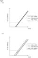
FIG. 4A is a graph schematically showing a valve closing characteristic in a supersonic flow of the capacity control valve in the first embodiment where a flow passage cross-sectional area tends to increase, andFIG. 4B is a graph schematically showing a valve closing characteristic of a comparative example where a flow passage cross-sectional area is constant. -
FIG. 5A is a graph schematically showing a valve closing characteristic in a subsonic flow of the capacity control valve in the first embodiment where the flow passage cross-sectional area tends to increase, andFIG. 5B is a graph schematically showing a valve closing characteristic of the comparative example where the flow passage cross-sectional area is constant. -
FIG. 6 is a cross-sectional view showing a state where a CS valve is opened in a non-energized state of a capacity control valve as a valve according to a second embodiment of the present invention. -
FIG. 7A is a cross-sectional view showing a state where a valve seat member is press-fitted into a valve housing of the capacity control valve in the second embodiment, andFIG. 7B is a view showing a Ps port when a cross section X-X ofFIG. 7A is viewed from a radially outer side of the valve housing. -
FIG. 8 is an enlarged cross-sectional view showing an increase region in a flow passage on a downstream side of the CS valve in an energized state (during normal control) of the capacity control valve in the second embodiment. - Modes for carrying out a valve according to the present invention will be described below based on embodiments. Incidentally, in the embodiments, a capacity control valve will be described as an example but the present invention is applicable to other uses.
- A capacity control valve as a valve according to a first embodiment of the present invention will be described with reference to
FIGS. 1 to 3 . Hereinafter, a description will be given based on the assumption that the left and right sides when seen from the front side ofFIG. 1 are left and right sides of the capacity control valve. In detail, a description will be given based on the assumption that the left side of the drawing sheet on which avalve housing 10 is disposed is the left side of the capacity control valve and the right side of the drawing sheet on which asolenoid 80 is disposed is the right side of the capacity control valve. - The capacity control valve of the present invention is assembled into a variable displacement compressor (not shown) used for an air conditioning system of an automobile, etc., and by variably controlling the pressure of a working fluid (hereinafter, simply referred to as a "fluid") that is a refrigerant, controls the discharge amount of the variable displacement compressor to adjust the air conditioning system to have a desired cooling capacity.
- First, the variable displacement compressor will be described. The variable displacement compressor includes a casing including a discharge chamber, a suction chamber, a control chamber, and a plurality of cylinders. Incidentally, the variable displacement compressor is provided with a communication passage that provides direct communication between the discharge chamber and the control chamber. The communication passage is provided with a
fixed orifice 9 that balances the pressures of the discharge chamber and the control chamber (refer toFIG. 1 ). - In addition, the variable displacement compressor includes a rotating shaft, a swash plate, and a plurality of pistons. The rotating shaft is rotationally driven by an engine (not shown) installed outside the casing. The swash plate is coupled to the rotating shaft so as to be tiltable by a hinge mechanism in the control chamber. The plurality of pistons are coupled to the swash plate and are reciprocatably fitted in the respective cylinders. The variable displacement compressor continuously changes the tilt angle of the swash plate by appropriately controlling pressure in the control chamber while utilizing a suction pressure Ps of the suction chamber that suctions the fluid, a discharge pressure Pd of the discharge chamber that discharges the fluid pressurized by the pistons, and a control pressure Pc of the control chamber that houses the swash plate, by means of the capacity control valve V1 to be driven to open and close by electromagnetic force, and thus changes the stroke amount of the pistons to control the discharge amount of the fluid.
- As shown in
FIG. 1 , the capacity control valve V1 of the first embodiment assembled into the variable displacement compressor adjusts an electric current that energizes acoil 86 forming thesolenoid 80 as a drive source, to perform opening and closing control of aCS valve 50 as a poppet valve in the capacity control valve V1. Accordingly, the fluid flowing out from the control chamber to the suction chamber is controlled to variably control the control pressure Pc in the control chamber. Incidentally, a discharge fluid of the discharge pressure Pd of the discharge chamber is constantly supplied to the control chamber via the fixedorifice 9, and theCS valve 50 in the capacity control valve V1 is closed, so that the control pressure Pc in the control chamber is increased. - In the capacity control valve V1 of the first embodiment, the
CS valve 50 includes aCS valve body 51 as a valve body and aCS valve seat 40a as a valve seat. TheCS valve seat 40a is formed in avalve seat member 40 having a tubular shape that is press-fitted and fixed to a recessedportion 10a of thevalve housing 10. Acontact portion 51a formed at an axially left end of theCS valve body 51 comes into contact with and separates from theCS valve seat 40a in an axial direction to open and close theCS valve 50. - Next, a structure of the capacity control valve V1 will be described. As shown in
FIG. 1 , the capacity control valve V1 mainly includes thevalve housing 10, thevalve seat member 40, theCS valve body 51, and thesolenoid 80. Thevalve housing 10 and thevalve seat member 40 are made of a metallic material. TheCS valve body 51 is disposed inside thevalve housing 10 so as to be reciprocatable in the axial direction. Thesolenoid 80 is connected to thevalve housing 10 to exert a driving force on theCS valve body 51. - As shown in
FIG. 1 , theCS valve body 51 includes a large-diameter portion 51b and a small-diameter portion 51c. The large-diameter portion 51b is made of a metallic material or a resin material and is a columnar body having a constant cross section. The small-diameter portion 51c extends from a radially inner side of an axially right end of the large-diameter portion 51b to the right in the axial direction. In addition, theCS valve body 51 also serves as a rod that is disposed through thecoil 86 of thesolenoid 80. - The
contact portion 51a having a curved shape in a cross-sectional view that bulges out toward theCS valve seat 40a is formed on an axially left end surface of theCS valve body 51, namely, on an axially left end surface of the large-diameter portion 51b. In detail, the curved shape of thecontact portion 51a is formed by a part of a spherical surface having a constant radius of curvature. Incidentally, the curved shape of thecontact portion 51a may not be formed by a part of a spherical surface having a constant radius of curvature as long as thecontact portion 51a can be seated on theCS valve seat 40a. - As shown in
FIG. 1 , thesolenoid 80 mainly includes acasing 81, acenter post 82, theCS valve body 51, amovable iron core 84, acoil spring 85, and thecoil 86 for excitation. Thecasing 81 includes anopening portion 81a that is open to the left in the axial direction. Thecenter post 82 is inserted into theopening portion 81a of thecasing 81 from the left in the axial direction to be disposed between a radially inner side of thecasing 81 and a radially inner side of thevalve housing 10, and has a substantially cylindrical shape. TheCS valve body 51 is inserted into thecenter post 82 to be reciprocatable in the axial direction, and an axially left end portion of theCS valve body 51 is disposed inside thevalve housing 10. An axially right end portion of theCS valve body 51 is inserted and fixed to themovable iron core 84. Thecoil spring 85 is provided between thecenter post 82 and themovable iron core 84 to urge themovable iron core 84 to the right in the axial direction, which is a valve opening direction of theCS valve 50. Thecoil 86 is wound on an outer side of thecenter post 82 with a bobbin interposed therebetween. - The
center post 82 includes acylindrical portion 82b and aflange portion 82d having an annular shape. Thecylindrical portion 82b is made of a rigid body that is a magnetic material such as iron or silicon steel, and aninsertion hole 82c which extends in the axial direction and into which theCS valve body 51 is inserted is formed in thecylindrical portion 82b. Theflange portion 82d extends from an outer peripheral surface of an axially left end portion of thecylindrical portion 82b in a radially outward direction. - As shown in
FIG. 1 , aPs port 11 as an outlet port is formed in thevalve housing 10. ThePs port 11 penetrates through thevalve housing 10 in a radial direction and communicates with the suction chamber of the variable displacement compressor. In addition, the recessedportion 10a into which thevalve seat member 40 having a tubular shape is press-fitted from the left in the axial direction is formed on an axially left side of thevalve housing 10. Incidentally, a Pc port as an inlet port is formed in thevalve housing 10. Thevalve seat member 40 is press-fitted and fixed to the recessedportion 10a, so that the Pc port communicates with the control chamber of the variable displacement compressor through a through-hole 40b penetrating through thevalve seat member 40 in the axial direction. - A
valve chamber 20 is formed inside thevalve housing 10, and thecontact portion 51a of theCS valve body 51 is disposed in thevalve chamber 20 so as to be reciprocatable in the axial direction. In addition, thePs port 11 extends from an outer peripheral surface of thevalve housing 10 in a radially inward direction to communicate with thevalve chamber 20. - As described above, inside the
valve housing 10, the through-hole 40b of thevalve seat member 40, thevalve chamber 20, and thePs port 11 form a flow passage that provides communication between the control chamber and the suction chamber of the variable displacement compressor. - In addition, a
guide hole 10c is formed in an inner peripheral surface of thevalve housing 10. Theguide hole 10c is formed on an axially right side of thevalve chamber 20, to which thesolenoid 80 is attached, and an outerperipheral surface 51d of the large-diameter portion 51b of the CS valve body 51 (refer toFIG. 3 ) is slidable on theguide hole 10c. Incidentally, an inner peripheral surface of theguide hole 10c and the outerperipheral surface 51d of the large-diameter portion 51b of theCS valve body 51 are slightly separated from each other in the radial direction to form a very small gap therebetween, and theCS valve body 51 is smoothly movable relative to thevalve housing 10 in the axial direction. - As shown in
FIG. 2 , an inner diameter R1 of the recessedportion 10a of thevalve housing 10 is set to be larger than an inner diameter R2 of the valve chamber 20 (R1 > R2), so that a bottom surface of the recessedportion 10a forms a receivingportion 10b that can come into contact with aflat surface 40c on an axially right side of thevalve seat member 40. - As shown in
FIG. 1 , a recessedportion 10d recessed to the left in the axial direction is formed on an axially right side of thevalve housing 10. Theflange portion 82d of thecenter post 82 is inserted and fixed to the recessedportion 10d from the right in the axial direction in a substantially sealed state, and thecasing 81 is inserted and fixed to thevalve housing 10 from the right in the axial direction in a substantially sealed state, so that thevalve housing 10, thecenter post 82, and thecasing 81 are integrally connected to each other. - As described above, in a state where the
valve housing 10, thecenter post 82, and thecasing 81 are integrally connected to each other, an axially right end surface of thevalve housing 10 and a side surface on an axially right side of theflange portion 82d of thecenter post 82 are in contact with a bottom surface of a recessedportion 81b formed on an axially left side of thecasing 81, and a bottom surface of the recessedportion 10d of thevalve housing 10 and an axially left end surface of thecenter post 82 are separated from each other in the axial direction to form a gap therebetween. - In addition, a through-
hole 21 is formed in thevalve housing 10. The through-hole 21 is formed to extend in the axial direction between an axially left end surface of thevalve housing 10 and a bottom portion of the recessedportion 10d. The through-hole 21 includes a small-diameter hole portion 211 of which an axially left end communicates with the control chamber of the variable displacement compressor, and a large-diameter hole portion 212 extending continuously from an axially right end of the small-diameter hole portion 211 and having a larger diameter than that of the small-diameter hole portion 211. An axially right end of the large-diameter hole portion 212 is open to the gap formed between the bottom surface of the recessedportion 10d and the axially left end surface of thecenter post 82. Incidentally, the control fluid of the control pressure Pc is supplied from the control chamber of the variable displacement compressor into the small-diameter hole portion 211 of the through-hole 21 and into the through-hole 40b of thevalve seat member 40. - An
actuating valve body 31 having a ball shape and areturn spring 32 of which an axially right end is fixed to the axially left end surface of thecenter post 82 and of which an axially left end is in contact with theactuating valve body 31 from the right in the axial direction are disposed in the large-diameter hole portion 212 of the through-hole 21. In addition, theactuating valve body 31 is urged to the left in the axial direction by thereturn spring 32. Theactuating valve body 31 and thereturn spring 32 form a pressure-actuatedvalve 30 that controls communication between the control chamber of the variable displacement compressor and an internal space S of thecasing 81 in the through-hole 21. - Although not shown for convenience of description, when the control pressure Pc is high, the
actuating valve body 31 of the pressure-actuatedvalve 30 moves to the right in the axial direction against an urging force of thereturn spring 32 and against the pressure of the fluid in the internal space S of thecasing 81, to be separated from avalve seat 213 having a tilted shape in a cross-sectional view that is formed at a connecting portion between the axially right end of the small-diameter hole portion 211 and an axially left end of the large-diameter hole portion 212 in the through-hole 21, so that the pressure-actuatedvalve 30 is opened. Accordingly, the control chamber of the variable displacement compressor and the internal space S of thecasing 81 communicate with each other via the through-hole 21, the control fluid of the control pressure Pc is supplied from the control chamber of the variable displacement compressor to the internal space S of thecasing 81 through the through-hole 21, and a difference between the pressure of the fluid in the internal space S of thecasing 81 and the pressure of the control fluid in the through-hole 40b of thevalve seat member 40 is reduced, so that theCS valve body 51 can be smoothly operated to the left in the axial direction, namely, in a valve closing direction, and responsiveness to control at a high output of the variable displacement compressor can be improved. - Incidentally, in the
valve housing 10, the very small gap between the inner peripheral surface of theguide hole 10c and the outer peripheral surface of the large-diameter portion 51b of theCS valve body 51 functions as a throttle. Accordingly, the fluid in the internal space S of thecasing 81 can be gently released to thePs port 11. During non-use for a long time, a state where a pressure difference between the pressure of the fluid in thevalve chamber 20 and the pressure of the fluid in the internal space S of thecasing 81 is small is maintained. - Here, the
valve seat member 40 will be described. As shown inFIG. 2 , thevalve seat member 40 is made of a metallic material harder than a metallic material used for thevalve housing 10. Further, thevalve seat member 40 may be made of a material that is different from that of theCS valve body 51. - In addition, the
valve seat member 40 has a tubular shape in which the through-hole 40b penetrating therethrough in the axial direction is formed. TheCS valve seat 40a having a tilted shape in a cross-sectional view is formed at an axially right end portion of thevalve seat member 40. Theflat surface 40c having an annular shape and theCS valve seat 40a that is continuous from a radially inner side of theflat surface 40c and that is gradually reduced in diameter toward the left in the axial direction are formed from a radially outer side to a radially inner side. Namely, theCS valve seat 40a is formed at an edge of the through-hole 40b as a through-flow passage and is formed of a tapered surface that is a tilted surface having a linear cross section and extending in a circumferential direction. - In addition, the
flat surface 40c on the axially right side of thevalve seat member 40 is brought into contact with the receivingportion 10b formed by the bottom surface of the recessedportion 10a, in the axial direction (refer toFIG. 3 ), so that the progress of insertion of thevalve seat member 40 into the recessedportion 10a can be defined, and the sealing property between thevalve housing 10 and thevalve seat member 40 can be improved. At this time, a radially outer end of the tapered surface forming theCS valve seat 40a is disposed to be continuous with an axially left end of an innerperipheral surface 10e in thevalve chamber 20 of thevalve housing 10. - Accordingly, a flow passage C1 formed between the tapered surface forming the
CS valve seat 40a of thevalve seat member 40 and thecontact portion 51a of theCS valve body 51, and a flow passage C2 formed between the tapered surface forming theCS valve seat 40a and the outerperipheral surface 51d of the large-diameter portion 51b of theCS valve body 51 and between the innerperipheral surface 10e of thevalve housing 10 and the outerperipheral surface 51d of the large-diameter portion 51b of theCS valve body 51 form a flow passage on a downstream side of theCS valve 50, the flow passage extending to an opening on avalve chamber 20 side of the Ps port 11 (refer toFIG. 3 ). Incidentally,FIG. 3 shows a state where theCS valve body 51 is stroked to a throttle position in the vicinity of a closing position during normal control of the capacity control valve V1. - In the first embodiment, the flow passage C1 forms an increase region where a flow passage cross-sectional area A2 between the tapered surface forming the
CS valve seat 40a and a radially outer end of thecontact portion 51a of theCS valve body 51 is larger than a flow passage cross-sectional area A1 between a radially inner end of the tapered surface forming theCS valve seat 40a and thecontact portion 51a of the CS valve body 51 (A1 < A2) and the flow passage cross-sectional area tends to increase toward a downstream side (dA > 0). In addition, the flow passage C2 forms an increase region where a flow passage cross-sectional area A4 between the innerperipheral surface 10e of thevalve housing 10 and the outerperipheral surface 51d of theCS valve body 51 is larger than a flow passage cross-sectional area A3 between the tapered surface forming theCS valve seat 40a and the outerperipheral surface 51d of the large-diameter portion 51b of the CS valve body 51 (A3 < A4) and the flow passage cross-sectional area tends to increase toward the downstream side (dA > 0). Incidentally, during normal control of the capacity control valve V1, in the state ofFIG. 3 where theCS valve body 51 is stroked to the throttle position, the flow passage cross-sectional area A3 on an upstream side of the flow passage C2 is larger than the flow passage cross-sectional area A2 on a downstream side of the flow passage C1 (A2 < A3). - Incidentally, the increase region is formed in a stroke range of the
contact portion 51a of theCS valve body 51 in the flow passage on the downstream side of theCS valve 50. - In addition, the flow passage cross-sectional area of the flow passage C1 continuously increases toward the downstream side. On the other hand, in the flow passage C2, since the inner
peripheral surface 10e of thevalve housing 10 and the outerperipheral surface 51d of theCS valve body 51 are disposed in parallel to each other, the flow passage cross-sectional area A4 on a downstream side of the flow passage C2 is constant. - Next, a change in the flow speed and the pressure of the fluid passing through the flow passages C1 and C2 on the downstream side of the
CS valve 50 will be described. Incidentally, the control pressure Pc will be described as being controlled within a range where the closing of the pressure-actuatedvalve 30 described above is maintained. A relational equation of cross-sectional area and pressure for the influence of an area change on an isentropic flow is shown below.
- p:
- pressure
- γ:
- specific heat ratio
- M:
- Mach number
- A:
- area
- When a pressure difference between the control pressure Pc in the through-
hole 40b of thevalve seat member 40 and the suction pressure Ps in thePs port 11, namely, a Pc - Ps differential pressure is large, and the fluid passing through theCS valve 50 flows at a supersonic speed (M > 1), based on the relational equation of cross-sectional area and pressure, the fluid passing through the flow passage C1 that is a flow passage on the downstream side of theCS valve 50 and that forms an increase region where the flow passage cross-sectional area tends to increase toward the downstream side (dA > 0) increases in flow speed and decreases in pressure. In addition, the fluid passing through the flow passage C2 that is continuous with the downstream side of the flow passage C1 and that forms an increase region where the flow passage cross-sectional area tends to increase toward the downstream side (dA > 0) further increases in flow speed and decreases in pressure and then passes through the downstream side of the flow passage C2 in which the flow passage cross-sectional area is constant, so that the fluid stably flows substantially without a change in flow speed and pressure and flows into the Ps port 11 (refer toFIG. 3 ). - On the other hand, when the Pc - Ps differential pressure is small and the fluid passing through the
CS valve 50 flows at a subsonic speed (M < 1), the fluid passing through the flow passage C1 that is a flow passage on the downstream side of theCS valve 50 and that forms an increase region decreases in flow speed and increases in pressure. In addition, the fluid passing through the flow passage C2 that is continuous with the downstream side of the flow passage C1 and that forms an increase region where the flow passage cross-sectional area tends to increase toward the downstream side (dA > 0) further decreases in flow speed and increases in pressure and then passes through the downstream side of the flow passage C2 in which the flow passage cross-sectional area is constant, so that the fluid stably flows substantially without a change in flow speed and pressure and flows into the Ps port 11 (refer toFIG. 3 ). - Incidentally, since the downstream pressure of the
CS valve 50, namely, the pressure of the fluid in thevalve chamber 20 is easily affected by the discharge pressure Pd that is constantly supplied via the fixed orifice 9 (refer toFIG. 1 ) to adjust the control pressure Pc in the control chamber of the variable displacement compressor, the pressure is less likely to decrease as compared to the pressure in thePs port 11. - In the first embodiment, as described above, when the fluid flows at a supersonic speed and passes through the increase regions, the downstream pressure of the
CS valve 50 can be reduced, so that the influence of the discharge pressure Pd on the pressure of the fluid in the internal space S of the casing 81 (refer toFIG. 1 ) that changes based on the pressure difference between the pressure of the fluid in thevalve chamber 20 and the pressure of the fluid in the internal space S, namely, on a force due to a back pressure acting on theCS valve body 51 can be suppressed. In addition, when the fluid flows at a subsonic speed and passes through the increase regions, in addition to the influence of the discharge pressure Pd, the downstream pressure of theCS valve 50 can be increased, so that the pressure of the fluid in the internal space S of thecasing 81 that changes based on the pressure difference between the pressure of the fluid in thevalve chamber 20 and the pressure of the fluid in the internal space S, namely, a force due to a back pressure acting on theCS valve body 51 can be further increased. - As described above, in the capacity control valve V1 of the first embodiment, the flow passage on the downstream side of the
CS valve 50 is provided with the flow passages C1 and C2 as increase regions where the flow passage cross-sectional area tends to increase toward the downstream side (dA > 0). When the fluid passing through theCS valve 50 flows at a supersonic speed (M > 1), the fluid passing through the flow passages C1 and C2 increases in flow speed and decreases in pressure, and a force in the valve opening direction acts on theCS valve body 51. Accordingly, as shown inFIG. 4A , the influence of the pressure of the fluid on an upstream side of theCS valve 50, in the present embodiment, the influence of the discharge pressure Pd on the downstream pressure of theCS valve 50 can be suppressed. Incidentally, in a reference graph ofFIG. 4B showing a characteristic of a flow passage in which the flow passage cross-sectional area is constant (dA = constant), a variation in driving electric current is large. As described above, the influence of the discharge pressure Pd on a force due to a back pressure acting on theCS valve body 51 can be suppressed, a variation in the stroke of theCS valve body 51 with respect to an electric current value input to thesolenoid 80 can be suppressed, and the opening degree of theCS valve 50 can be accurately adjusted. - In addition, when the fluid passing through the
CS valve 50 flows at a subsonic speed (M < 1), the fluid passing through the flow passages C1 and C2 decreases in flow speed and increases in pressure, and a force in the valve closing direction acts on theCS valve body 51. In addition, a force due to a back pressure acting on theCS valve body 51 which is affected by the discharge pressure Pd can be further increased. For this reason, as shown inFIG. 5A , the valve closing characteristic of theCS valve 50 can be improved, and theCS valve 50 can be closed with a small electric current value. Incidentally, in a reference graph ofFIG. 5B showing a characteristic of a flow passage in which the flow passage cross-sectional area is constant (dA = constant), when the discharge pressure Pd is high, the valve cannot be closed, in other words, a large electric current is required to close the valve. - As described above, the flow passage on the downstream side of the
CS valve 50 is provided with the flow passages C1 and C2 that are increase regions where the flow passage cross-sectional area tends to increase toward the downstream side (dA > 0), and the downstream pressure of theCS valve 50 is appropriately controlled according to the flow speed of the fluid passing through theCS valve 50, so that the controllability of theCS valve 50 can be improved. - In addition, in the flow passage C1 as an increase region, the flow passage cross-sectional area continuously increases toward the downstream side, so that the flow of the fluid can be stabilized to eliminate stagnation. In addition, the flow speed or pressure of the fluid passing through the flow passage C1 can be changed in an accelerating manner.
- In addition, since the
CS valve 50 includes theCS valve seat 40a having a tilted shape in a cross-sectional view and thecontact portion 51a having a curved shape in a cross-sectional view in theCS valve body 51, and the flow passage C1 as an increase region is formed between the tapered surface forming theCS valve seat 40a and thecontact portion 51a of theCS valve body 51, the flow of the fluid passing through theCS valve 50 at the valve closing position or the throttle position of theCS valve body 51 can be stabilized in a tangential direction (refer to a solid arrow inFIG. 3 ). - In addition, since the
CS valve seat 40a is formed of the tapered surface that is a tilted surface having a linear cross section and extending in the circumferential direction, the flow of the fluid passing through theCS valve 50 at the valve closing position or the throttle position of theCS valve body 51, in detail, the flow of the fluid on an upstream side of the flow passages C1 and C2 can be stabilized in the tangential direction, and the flow of the fluid can be guided along the tilted surface, the flow of the fluid can be stabilized to the downstream side of theCS valve 50. - In addition, the tapered surface forming the
CS valve seat 40a may be located downstream along a normal line of thecontact portion 51a of theCS valve body 51, and accordingly, the fluid that has passed through the increase regions travels linearly, so that the flow speed of the fluid close to the speed of sound is unlikely to be interfered with. - In addition, on the downstream side of the flow passage C2, the flow passage cross-sectional area is constant to the opening on the
valve chamber 20 side of thePs port 11, and the flow of the fluid can be stabilized substantially without a change in the flow speed and the pressure of the passing fluid, so that the pressure of the fluid in thevalve chamber 20 is easily stabilized. - In addition, since the flow passage C1 can form an increase region by using the tapered surface forming the
CS valve seat 40a of theCS valve 50 as a poppet valve and thecontact portion 51a of theCS valve body 51, the structure of the capacity control valve V1 can be simplified. - In addition, since the
CS valve seat 40a is formed in thevalve seat member 40 that is separate from thevalve housing 10, the accuracy of processing of the tapered surface for forming an increase region can be improved. - Incidentally, in the first embodiment, a mode has been described in which the flow passage cross-sectional area on the downstream side of the flow passage C2 that is continuous with the downstream side of the flow passage C1 is made constant by disposing the inner
peripheral surface 10e of thevalve housing 10 and the outerperipheral surface 51d of theCS valve body 51 in parallel to each other, but the present invention is not limited to the mode, and the shape of the innerperipheral surface 10e of thevalve housing 10 or of the outerperipheral surface 51d of theCS valve body 51 may be changed such that an increase region where the flow passage cross-sectional area tends to increase toward the downstream side (dA > 0) is also continuously formed on the downstream side of the flow passage C2. - A capacity control valve as a valve according to a second embodiment of the present invention will be described with reference to
FIGS. 6 to 8 . Incidentally, a description of duplicated configurations that are the same as the configurations of the first embodiment will be omitted. - As shown in
FIG. 6 , in a capacity control valve V2 according to the second embodiment of the present invention, aPs port 111 is formed in avalve housing 110, as an outlet port that penetrates through thevalve housing 110 in the radial direction and communicates with the suction chamber of the variable displacement compressor. - In addition, a first recessed
portion 110a is formed on an axially left side of thevalve housing 110. Avalve seat member 140 having a flanged tubular shape is press-fitted into the first recessedportion 110a from the left in the axial direction. Incidentally, when thevalve seat member 140 is press-fitted and fixed to the first recessedportion 110a, a Pc port as an inlet port communicating with the control chamber of the variable displacement compressor through a through-hole 140b penetrating through thevalve seat member 140 in the axial direction is formed in thevalve housing 110. - Inside the
valve housing 110, the first recessedportion 110a and a second recessedportion 110b having a small diameter that is continuously formed on an axially right side of the first recessedportion 110a form avalve chamber 120. Thecontact portion 51a of theCS valve body 51 is disposed in thevalve chamber 120 so as to be reciprocatable in the axial direction. In addition, thePs port 111 extends from an outer peripheral surface of thevalve housing 110 in the radially inward direction to communicate with thevalve chamber 120. - As shown in
FIG. 7A , an inner diameter R11 of the first recessedportion 110a of thevalve housing 110 is set to be larger than an inner diameter R12 of the second recessedportion 110b (R11 > R12), so that astep portion 114 having an annular shape is formed in thevalve chamber 120 by an innerperipheral surface 110d of the first recessedportion 110a, abottom surface 110e extending from an axially right end of the innerperipheral surface 110d of the first recessedportion 110a in the radially inward direction, and an innerperipheral surface 110f of the second recessedportion 110b extending from a radially inner end of thebottom surface 110e of the first recessedportion 110a to the right in the axial direction. Incidentally, thestep portion 114 having an annular shape is interrupted in the circumferential direction at the position of thePs port 111. - In addition, an opening on a
valve chamber 120 side of thePs port 111 is disposed to lie between the innerperipheral surface 110d of the first recessedportion 110a and the innerperipheral surface 110f of the second recessedportion 110b in the axial direction, and has a step shape. In addition, the opening on thevalve chamber 120 side communicates with the first recessedportion 110a and with the second recessedportion 110b and is also open to the left in the axial direction at thebottom surface 110e of the first recessedportion 110a to communicate with the first recessedportion 110a (refer toFIG. 7B ). - As shown in
FIG. 7A , thevalve seat member 140 has a tubular shape in which the through-hole 140b penetrating therethrough in the axial direction is formed. ACS valve seat 140a as a valve seat is formed at an axially right end portion of thevalve seat member 140. Aflat surface 140c having an annular shape and theCS valve seat 140a having a tilted shape in a cross-sectional view that is continuous from a radially inner side of theflat surface 140c and that is gradually reduced in diameter toward the left in the axial direction are formed from a radially outer side to a radially inner side. Namely, theCS valve seat 140a is formed at an edge of the through-hole 140b as a through-flow passage and is formed of a tapered surface that is a tilted surface having a linear cross section and extending in the circumferential direction. - In addition, a
flange portion 140d protruding an outer peripheral surface of thevalve seat member 140 in the radially outward direction is formed at an axially left end portion of thevalve seat member 140, and a side surface on an axially right side of theflange portion 140d is brought into contact with an axially left end surface of thevalve housing 110 in the axial direction (refer toFIG. 8 ), so that the progress of insertion of thevalve seat member 140 into the first recessedportion 110a can be defined. At this time, a radially outer end of theflat surface 140c is disposed to be continuous with an inner peripheral surface of thePs port 111 in the radial direction, thePs port 111 being open to the innerperipheral surface 110d of the first recessedportion 110a of thevalve housing 110. In addition, a radially outer end of the tapered surface forming theCS valve seat 140a is located on a radially outer side of the second recessedportion 110b of thevalve housing 110. Namely, the tapered surface forming theCS valve seat 140a extends to a position at which the tapered surface overlaps the opening on thevalve chamber 120 side of thePs port 111 in the axial direction. - Accordingly, a flow passage C101 formed between the tapered surface forming the
CS valve seat 140a of thevalve seat member 140 and thecontact portion 51a of theCS valve body 51, a flow passage C102 formed between the tapered surface forming theCS valve seat 140a of thevalve seat member 140 and the outerperipheral surface 51d of the large-diameter portion 51b of theCS valve body 51, and a flow passage C103 formed between theflat surface 140c of thevalve seat member 140 and thebottom surface 110e of the first recessedportion 110a forming thestep portion 114 form a flow passage on the downstream side of theCS valve 50, the flow passage extending to the opening having a stepped shape on thevalve chamber 120 side of the Ps port 111 (refer toFIG. 8 ). Incidentally,FIG. 8 shows a state where theCS valve body 51 is stroked to a throttle position in the vicinity of a closing position during normal control of the capacity control valve V2. - In the second embodiment, the flow passage C101 forms an increase region where a flow passage cross-sectional area A102 between the tapered surface forming the
CS valve seat 140a and the radially outer end of thecontact portion 51a of theCS valve body 51 is larger than a flow passage cross-sectional area A101 between a radially inner end of the tapered surface forming theCS valve seat 140a and thecontact portion 51a of the CS valve body 51 (A101 < A102) and the flow passage cross-sectional area tends to increase toward a downstream side (dA > 0). In addition, the flow passage C102 forms an increase region where a radially outer portion of the tapered surface forming theCS valve seat 140a extends linearly to the position at which the radially outer portion overlaps the opening on thevalve chamber 120 side of thePs port 111 in the axial direction, so that a flow passage cross-sectional area A103 on an upstream side of the flow passage C102 is larger than the flow passage cross-sectional area A102 on a downstream side of the flow passage C101 (A102 < A103) and the flow passage cross-sectional area tends to increase toward the downstream side (dA > 0). - In addition, the flow passage cross-sectional area of the flow passage C101 continuously increases toward the downstream side. In addition, the flow passage cross-sectional area of the flow passage C102 also continuously increases toward the downstream side, but since the outer
peripheral surface 51d of theCS valve body 51 extends linearly in the axial direction with respect to the tapered surface forming theCS valve seat 140a, an increase amount of the flow passage cross-sectional area is larger than that of the flow passage C101. - In addition, the flow passage C103 corresponds to a space of a radially outer portion of the first recessed
portion 110a and communicates with the opening having a stepped shape on thevalve chamber 120 side of thePs port 111 at the innerperipheral surface 110d and thebottom surface 110e of the first recessedportion 110a. - In addition, as shown in
FIG. 6 , the tapered surface forming theCS valve seat 140a extends over an entire stroke region of thecontact portion 51a of theCS valve body 51. - According to this configuration, in the capacity control valve V2 of the second embodiment, the flow passage on the downstream side of the
CS valve 50 is provided with the flow passages C101 and C102 as increase regions where the flow passage cross-sectional area tends to increase toward the downstream side (dA > 0). When the fluid passing through theCS valve 50 flows at a supersonic speed (M > 1), the fluid passing through the flow passages C101 and C102 increases in flow speed and decreases in pressure, and a force in the valve opening direction acts on theCS valve body 51. Accordingly, the influence of the pressure of the fluid on the upstream side of theCS valve 50, in the present embodiment, the influence of the discharge pressure Pd on the downstream pressure of theCS valve 50 can be suppressed. As described above, the influence of the discharge pressure Pd on a force due to a back pressure acting on theCS valve body 51 can be suppressed, a variation in the stroke of theCS valve body 51 with respect to an electric current value input to thesolenoid 80 can be suppressed, and the opening degree of theCS valve 50 can be accurately adjusted. - In addition, when the fluid passing through the
CS valve 50 flows at a subsonic speed (M < 1), the fluid passing through the flow passages C101 and C102 decreases in flow speed and increases in pressure, and a force in the valve closing direction acts on theCS valve body 51. In addition, a force due to a back pressure acting on theCS valve body 51 which is affected by the discharge pressure Pd can be further increased. For this reason, the valve closing characteristic of theCS valve 50 can be improved, and theCS valve 50 can be closed with a small electric current value. - As described above, the flow passage on the downstream side of the
CS valve 50 is provided with the flow passages C101 and C102 that are increase regions where the flow passage cross-sectional area tends to increase toward the downstream side (dA > 0), and the downstream pressure of theCS valve 50 is appropriately controlled according to the flow speed of the fluid passing through theCS valve 50, so that the controllability of theCS valve 50 can be improved. - In addition, since the
CS valve seat 140a forming the flow passages C101 and C102 as increase regions is formed of the tapered surface extending linearly to the position at which the radially outer portion of the tapered surface overlaps the opening on thevalve chamber 120 side of thePs port 111 in the axial direction, the fluid is easily guided into thePs port 111 while changing the flow speed or pressure of the fluid in an accelerating manner. Accordingly, the flow of the fluid in the flow passage on the downstream side of theCS valve 50 can be stabilized to eliminate stagnation, and the downstream pressure of theCS valve 50, namely, the pressure of the fluid in thevalve chamber 120 can be more stabilized. - In addition, since the
CS valve seat 140a is formed in thevalve seat member 140 that is separate from thevalve housing 110, the accuracy of processing of the tapered surface for forming an increase region can be improved. Further, the tapered surface forming theCS valve seat 140a can be extended to the vicinity of thePs port 111. - Incidentally, in the second embodiment, the
valve seat member 140 may not have theflat surface 140c, and the tapered surface forming theCS valve seat 140a may be continuous with the outer peripheral surface of thevalve seat member 140. In addition, in this case, since the radially outer end of the tapered surface forming theCS valve seat 140a is continuous with the opening on thevalve chamber 120 side of thePs port 111, thestep portion 114 having an annular shape may not be formed in the inner peripheral surface of thevalve housing 110. - The embodiments of the present invention have been described above with reference to the drawings; however, the specific configurations are not limited to the embodiments, and the present invention also includes changes or additions that are made without departing from the scope of the present invention.
- For example, in the embodiments, the valve housing and the valve seat member have been described as being made of a metallic material; however, the present invention is not limited thereto, and the valve seat member may be made of a resin material, etc. as long as the hardness of the valve seat member is harder than a hardness of a flow passage inner side of the valve housing. In addition, also in this case, it is preferable that the valve seat member is made of a material which is different from that of the valve body.
- In addition, the contact portion of the CS valve body that comes into contact with and separates from the CS valve seat may not be formed in a curved shape in a cross-sectional view.
- In addition, the tapered surface forming the CS valve seat is not limited to having a linear shape and may have an arc shape.
- In addition, the increase region is not limited to a mode where the flow passage cross-sectional area continuously increases due to the tapered surface, and may show an increase tendency where the flow passage cross-sectional area increases in a stepwise manner due to a stepped surface.
- In addition, in the first and second embodiments, both the flow passages C1 and C2 or both the flow passages C101 and C102 that are continuous on the downstream side of the
CS valve 50 have been described as forming increase regions, but the present invention is not limited thereto, and for example, either of the upstream flow passages C1 and C101 and the downstream flow passages C2 and C102 may form increase regions. - In addition, in the capacity control valves of the embodiments, the CS valve as a poppet valve has been described as an example, but the poppet valve may be a DC valve that opens and closes the flow passage between a Pd port as an inlet port and the Pc port as an outlet port.
-
- 9
- Fixed orifice
- 10
- Valve housing
- 10a
- Recessed portion
- 10b
- Receiving portion
- 10c
- Guide hole
- 10d
- Recessed portion
- 10e
- Inner peripheral surface
- 11
- Ps port (outlet port)
- 20
- Valve chamber
- 21
- Through-hole
- 30
- Pressure-actuated valve
- 40
- Valve seat member
- 40a
- CS valve seat (valve seat)
- 40b
- Through-hole (through-flow passage, inlet port)
- 40c
- Flat surface
- 50
- CS valve (poppet valve)
- 51
- CS valve body (valve body)
- 51a
- Contact portion
- 51d
- Outer peripheral surface
- 80
- Solenoid (drive source)
- 110
- Valve housing
- 110a
- First recessed portion
- 110b
- Second recessed portion
- 110d
- Inner peripheral surface
- 110e
- Bottom surface
- 110f
- Inner peripheral surface
- 111
- Ps port (outlet port)
- 114
- Step portion
- 120
- Valve chamber
- 140
- Valve seat member
- 140a
- CS valve seat (valve seat)
- 140b
- Through-hole (through-flow passage, inlet port)
- 140c
- Flat surface
- 140d
- Flange portion
- C1, C2
- Flow passage (increase region, flow passage on downstream side)
- C101,
- C102 Flow passage (increase region, flow passage on downstream side)
- C103
- Flow passage (flow passage on downstream side)
- S
- Space
- V1, V2
- Capacity control valve (valve)
Claims (6)
- A valve, comprising:a valve housing provided with an inlet port and an outlet port;a valve body to be driven by a drive source;a spring that urges the valve body in a direction opposite a direction of driving by the drive source; anda valve seat formed at an edge of a through-flow passage the valve body and the valve seat cooperatively forming a poppet valve, the valve being configured to control a flow rate in accordance with a movement of the valve body,wherein a flow passage on a downstream side of the poppet valve is provided with an increase region where a flow passage cross-sectional area tends to increase toward the downstream side.
- The valve according to claim 1,
wherein the flow passage cross-sectional area of the increase region continuously increases. - The valve according to claim 1 or 2,
wherein the valve seat has a tilted shape in a cross-sectional view and the valve body has a curved shape in a cross-sectional view. - The valve according to claim 3,
wherein the tilted shape is a linear shape. - The valve according to claim 3 or 4,
wherein a tilted surface forming the valve seat is continuous with an opening of the outlet port. - The valve according to any one of claims 1 to 5,
wherein the valve seat is formed in a valve seat member that is separate from the valve housing.
Applications Claiming Priority (2)
| Application Number | Priority Date | Filing Date | Title |
|---|---|---|---|
| JP2020132385 | 2020-08-04 | ||
| PCT/JP2021/027767 WO2022030312A1 (en) | 2020-08-04 | 2021-07-27 | Valve |
Publications (2)
| Publication Number | Publication Date |
|---|---|
| EP4194724A1 true EP4194724A1 (en) | 2023-06-14 |
| EP4194724A4 EP4194724A4 (en) | 2024-04-24 |
Family
ID=80117383
Family Applications (1)
| Application Number | Title | Priority Date | Filing Date |
|---|---|---|---|
| EP21852577.2A Pending EP4194724A4 (en) | 2020-08-04 | 2021-07-27 | VALVE |
Country Status (6)
| Country | Link |
|---|---|
| US (1) | US12297913B2 (en) |
| EP (1) | EP4194724A4 (en) |
| JP (1) | JP7673070B2 (en) |
| KR (1) | KR102891392B1 (en) |
| CN (1) | CN116157609A (en) |
| WO (1) | WO2022030312A1 (en) |
Family Cites Families (258)
| Publication number | Priority date | Publication date | Assignee | Title |
|---|---|---|---|---|
| US821758A (en) | 1904-07-18 | 1906-05-29 | Alva C Ricksecker | Valve. |
| US813555A (en) | 1905-04-13 | 1906-02-27 | Crane Co | Spring-disk valve. |
| US877865A (en) | 1905-05-06 | 1908-01-28 | Ajax Valve Company | Valve. |
| US1449876A (en) | 1920-07-12 | 1923-03-27 | Williams William Erastus | Poppet-valve head |
| US1614002A (en) | 1923-12-05 | 1927-01-11 | Horton Spencer | Valve for automatic sprinkler apparatus for fire extinguishing |
| US1800127A (en) | 1926-01-25 | 1931-04-07 | Wilson Rings Company | Valve |
| US1758471A (en) | 1926-02-12 | 1930-05-13 | Schmidt Georg Julius | Valve |
| US1847385A (en) | 1930-05-26 | 1932-03-01 | Dengler Benjamin Franklin | Valve |
| US2196798A (en) | 1936-06-15 | 1940-04-09 | Horstmann Frederick Otto | Tap or valve |
| US2267515A (en) | 1940-01-19 | 1941-12-23 | California Cedar Prod | Fluid control valve |
| US2331503A (en) | 1942-05-26 | 1943-10-12 | William A Ray | Fluid control valve |
| US2797061A (en) | 1953-09-22 | 1957-06-25 | J D Buchanan | Solenoid operated shut-off valve |
| US2898082A (en) | 1956-08-09 | 1959-08-04 | Macclatchie Mfg Company | High pressure pump valve |
| US2893685A (en) | 1957-07-03 | 1959-07-07 | Automatic Switch Co | Valve having resilient wafer-like disc closure |
| US2887293A (en) | 1958-09-22 | 1959-05-19 | Autoclave Eng Inc | Valve |
| US3054422A (en) | 1958-09-26 | 1962-09-18 | Pellegrino E Napolitano | Fluid seal for pressure responsive valve |
| US3070120A (en) | 1960-12-23 | 1962-12-25 | L K Pump Valve Company | Valve and sealing gasket therefor |
| US3049332A (en) | 1961-11-28 | 1962-08-14 | Tri Kris Company Inc | High pressure valve, shank and stem assembly |
| US3204925A (en) | 1962-05-15 | 1965-09-07 | Montuori Enrico | Valve with nonrotating valve stem |
| DE1229924B (en) | 1962-06-09 | 1966-12-08 | Junkers & Co | Gas valve |
| US3185438A (en) | 1962-08-17 | 1965-05-25 | Johannes R Smirra | Cone labyrinth valve |
| US3360304A (en) | 1964-11-09 | 1967-12-26 | Abex Corp | Retarder systems |
| US3394732A (en) | 1965-04-26 | 1968-07-30 | Protectoseal Co | Valve seal |
| US3278156A (en) | 1965-12-27 | 1966-10-11 | Nuclear Products Company | Bellows valve |
| US3483888A (en) | 1967-12-15 | 1969-12-16 | Waldes Kohinoor Inc | Self-locking retaining rings and assemblies employing same |
| US3426741A (en) | 1968-04-03 | 1969-02-11 | Thomas E Haagen | Diesel engine poppet valve |
| CH485156A (en) | 1968-12-23 | 1970-01-31 | Lucifer Sa | Electromagnetically operated valve, including vacuum valve |
| US3623699A (en) | 1969-05-07 | 1971-11-30 | Whitey Research Tool Co | Valve with raised sealing seat abutting a soft annular ring and stem |
| BE754966A (en) | 1969-10-01 | 1971-02-18 | Sno Trik Co | HIGH PRESSURE VALVES |
| US3854495A (en) | 1972-05-08 | 1974-12-17 | J Cowley | Pressure regulator |
| DE2414893C2 (en) | 1974-03-28 | 1985-01-17 | Honeywell-Braukmann GmbH, 6950 Mosbach | Backflow preventer |
| US3981283A (en) * | 1974-09-03 | 1976-09-21 | Ford Motor Company | Engine exhaust gas recirculating control |
| US4085921A (en) | 1975-04-09 | 1978-04-25 | Matsushita Electric Industrial Co., Ltd. | Multiple-mode fluid-flow control valve arrangement |
| DE2706439C2 (en) | 1977-02-16 | 1982-05-06 | Wabco Fahrzeugbremsen Gmbh, 3000 Hannover | Main shut-off valve for switching actuation of transmissions |
| US4149699A (en) | 1977-05-06 | 1979-04-17 | Gould Inc. | Union bonnet valve |
| CH637745A5 (en) | 1979-02-01 | 1983-08-15 | Balzers Hochvakuum | Hochvakuum valve. |
| US4448038A (en) | 1979-10-01 | 1984-05-15 | Sporlan Valve Company | Refrigeration control system for modulating electrically-operated expansion valves |
| US4345739A (en) | 1980-08-07 | 1982-08-24 | Barton Valve Company | Flanged sealing ring |
| US4364615A (en) | 1980-09-08 | 1982-12-21 | The Bendix Corporation | Retaining ring |
| US4417601A (en) | 1980-12-19 | 1983-11-29 | National Foam Systems, Inc. | Variable proportioning valve for balanced pressure proportioning systems, and system containing the valve |
| US4474356A (en) | 1982-05-07 | 1984-10-02 | Baumann Hans D | Control valve with integral streamlined seating means |
| GB8315079D0 (en) | 1983-06-01 | 1983-07-06 | Sperry Ltd | Pilot valves for two-stage hydraulic devices |
| DE8322570U1 (en) | 1983-08-05 | 1985-01-17 | Robert Bosch Gmbh, 7000 Stuttgart | PRESSURE REGULATOR |
| US4617889A (en) | 1984-04-11 | 1986-10-21 | Hitachi, Ltd. | Idle speed control device |
| US4632358A (en) | 1984-07-17 | 1986-12-30 | Eaton Corporation | Automotive air conditioning system including electrically operated expansion valve |
| KR870006308A (en) * | 1985-12-10 | 1987-07-10 | 미타 가쓰시게 | Car idle control device |
| GB2186035B (en) | 1986-01-23 | 1989-11-01 | Fort Vale Eng Ltd | Seal |
| US4778150A (en) | 1987-03-06 | 1988-10-18 | Autoclave Engineers, Inc. | Non-rotating stem valve |
| US4895192A (en) | 1987-12-24 | 1990-01-23 | Sundstrand Corporation | Process and apparatus for filling a constant speed drive |
| US4848729A (en) | 1988-02-01 | 1989-07-18 | Dresser Industries, Inc. | Valve seal |
| US4825909A (en) | 1988-02-24 | 1989-05-02 | Diesel Equipment Limited | High pressure hydraulic flow control valve |
| DE3814156A1 (en) | 1988-04-27 | 1989-11-09 | Mesenich Gerhard | PULSE-MODULATED HYDRAULIC VALVE |
| US4917150A (en) | 1988-07-29 | 1990-04-17 | Colt Industries Inc. | Solenoid operated pressure control valve |
| US4998559A (en) | 1988-09-13 | 1991-03-12 | Coltec Industries Inc. | Solenoid operated pressure control valve |
| US4922957A (en) | 1989-03-08 | 1990-05-08 | National-Oilwell | Valve with replaceable seal element |
| US4923173A (en) | 1989-10-30 | 1990-05-08 | Vilter Manufacturing Corporation | Seating seal means for disc-type valve |
| US5011116A (en) | 1990-03-30 | 1991-04-30 | Keystone International Holdings Corp. | Shock absorbing sealing means for flow control devices |
| US5060695A (en) | 1990-04-02 | 1991-10-29 | Coltec Industries Inc | Bypass flow pressure regulator |
| JPH04171361A (en) * | 1990-10-31 | 1992-06-18 | Hitachi Constr Mach Co Ltd | hydraulic drive |
| IT1245443B (en) | 1991-03-08 | 1994-09-20 | Fiat Auto Spa | FLOW REGULATING VALVE |
| WO1992018795A1 (en) | 1991-04-10 | 1992-10-29 | Barreme Pty. Ltd. | A valve assembly |
| US5217047A (en) | 1991-05-30 | 1993-06-08 | Coltec Industries Inc. | Solenoid operated pressure regulating valve |
| US5263694A (en) | 1992-02-24 | 1993-11-23 | General Motors Corporation | Upper mount assembly for a suspension damper |
| US5246205A (en) | 1992-04-06 | 1993-09-21 | Donaldson Company, Inc. | Valve assembly and use |
| JP3131036B2 (en) | 1992-07-07 | 2001-01-31 | 株式会社鷺宮製作所 | Solenoid proportional control valve |
| JP2742001B2 (en) | 1993-06-29 | 1998-04-22 | 川崎製鉄株式会社 | Pulverized coal injection control method |
| US5364066A (en) | 1993-07-15 | 1994-11-15 | Sporlan Valve Company | Dual port valve with stepper motor actuator |
| US5409036A (en) | 1993-09-27 | 1995-04-25 | General Electric Company | Electromagnetically operated pneumatic valve assembly for an electrical contactor actuator |
| US5439027A (en) | 1994-01-21 | 1995-08-08 | Halliburton Company | High pressure regulating valve |
| JPH08159320A (en) | 1994-12-05 | 1996-06-21 | Fuji Koki Seisakusho:Kk | Motor-driven flow control valve |
| US5702235A (en) | 1995-10-31 | 1997-12-30 | Tgk Company, Ltd. | Capacity control device for valiable-capacity compressor |
| JPH09144931A (en) | 1995-11-22 | 1997-06-03 | Aisin Aw Co Ltd | Linear solenoid |
| US6010312A (en) | 1996-07-31 | 2000-01-04 | Kabushiki Kaisha Toyoda Jidoshokki Seiksakusho | Control valve unit with independently operable valve mechanisms for variable displacement compressor |
| JPH10220926A (en) | 1997-02-03 | 1998-08-21 | Denso Corp | Electric expansion valve |
| DE19705850C2 (en) | 1997-02-15 | 2000-06-08 | Daimlerchrysler Aerospace Ag | Cryogenic valve |
| DE29706717U1 (en) | 1997-04-14 | 1997-07-17 | Bürkert Werke GmbH & Co., 74653 Ingelfingen | Broadband valve |
| US5778932A (en) | 1997-06-04 | 1998-07-14 | Vickers, Incorporated | Electrohydraulic proportional pressure reducing-relieving valve |
| JP4048512B2 (en) | 1998-03-31 | 2008-02-20 | 株式会社日立製作所 | Damping force adjustable hydraulic shock absorber |
| JP3475795B2 (en) | 1998-07-01 | 2003-12-08 | オムロン株式会社 | Automatic ticket gate |
| JP2000220763A (en) | 1999-01-29 | 2000-08-08 | Toyota Autom Loom Works Ltd | Capacity control valve for variable displacement compressor |
| US6161585A (en) | 1999-03-26 | 2000-12-19 | Sterling Hydraulics, Inc. | High flow proportional pressure reducing valve |
| JP4075207B2 (en) | 1999-04-22 | 2008-04-16 | 株式会社デンソー | Flow control valve |
| JP3583951B2 (en) | 1999-06-07 | 2004-11-04 | 株式会社豊田自動織機 | Capacity control valve |
| JP4161151B2 (en) | 1999-06-30 | 2008-10-08 | 株式会社日立製作所 | Damping force adjustable hydraulic shock absorber |
| JP3428926B2 (en) | 1999-07-12 | 2003-07-22 | 株式会社テージーケー | Pilot operated flow control valve |
| US6321995B1 (en) | 1999-10-21 | 2001-11-27 | Parker-Hannifin Corporation | Thermostatic expansion valve |
| JP2001153498A (en) | 1999-12-01 | 2001-06-08 | Tgk Co Ltd | Supercooling degree control type expansion valve |
| JP3840354B2 (en) | 1999-12-01 | 2006-11-01 | 株式会社テージーケー | Electrically controlled expansion valve |
| JP2001165055A (en) | 1999-12-09 | 2001-06-19 | Toyota Autom Loom Works Ltd | Control valve and displacement variable compressor |
| US6811140B1 (en) | 1999-12-21 | 2004-11-02 | Sanjeev Maini | Shut-off valve assembly |
| JP2001263527A (en) | 2000-03-17 | 2001-09-26 | Pacific Ind Co Ltd | Pilot type solenoid valve |
| JP2001280523A (en) * | 2000-03-31 | 2001-10-10 | Tokico Ltd | solenoid valve |
| JP2002216803A (en) | 2001-01-19 | 2002-08-02 | Sony Corp | Fuel cell, method for producing and using the same |
| JP2002286151A (en) | 2001-03-26 | 2002-10-03 | Denso Corp | solenoid valve |
| JP2002295711A (en) | 2001-04-02 | 2002-10-09 | Aisan Ind Co Ltd | High pressure on-off valve device |
| JP2003004160A (en) | 2001-06-25 | 2003-01-08 | Fuji Koki Corp | Motor-operated valve |
| JP4006218B2 (en) | 2001-10-30 | 2007-11-14 | 京三電機株式会社 | Stop valve seal structure |
| JP3846287B2 (en) | 2001-11-27 | 2006-11-15 | 三浦工業株式会社 | valve |
| JP4246975B2 (en) | 2002-02-04 | 2009-04-02 | イーグル工業株式会社 | Capacity control valve |
| JP2003278230A (en) * | 2002-03-22 | 2003-10-02 | Aisin Seiki Co Ltd | Cleaning water injection mechanism for human body local cleaning equipment |
| JP4162419B2 (en) | 2002-04-09 | 2008-10-08 | サンデン株式会社 | Variable capacity compressor |
| JP4110512B2 (en) | 2002-04-18 | 2008-07-02 | Smc株式会社 | Vacuum pressure regulating valve |
| DE10318626A1 (en) | 2002-04-25 | 2003-11-13 | Sanden Corp | Variable capacity compressor |
| JP4195633B2 (en) | 2002-04-25 | 2008-12-10 | サンデン株式会社 | Variable displacement compressor with displacement control valve |
| JP2004190495A (en) | 2002-12-06 | 2004-07-08 | Toyota Industries Corp | Variable displacement structure of variable displacement compressor |
| JP2004101163A (en) | 2002-07-16 | 2004-04-02 | Tgk Co Ltd | Constant flow rate expansion valve |
| JP2004098757A (en) | 2002-09-05 | 2004-04-02 | Toyota Industries Corp | Air conditioner |
| US6626000B1 (en) | 2002-10-30 | 2003-09-30 | Visteon Global Technologies, Inc. | Method and system for electronically controlled high side pressure regulation in a vapor compression cycle |
| US7159615B2 (en) | 2003-02-12 | 2007-01-09 | Isuzu Motors Limited | Flow control valve |
| JP2005030586A (en) | 2003-07-07 | 2005-02-03 | Lg Electron Inc | Electromagnetic fluid control valve |
| JP4316955B2 (en) | 2003-08-11 | 2009-08-19 | イーグル工業株式会社 | Capacity control valve |
| JP2005098597A (en) | 2003-09-25 | 2005-04-14 | Tgk Co Ltd | Refrigerating cycle |
| US20070145315A1 (en) | 2003-11-14 | 2007-06-28 | Norio Uemura | Capacity control valve |
| US20050151310A1 (en) | 2004-01-14 | 2005-07-14 | Barnes Group, Inc., A Corp. Of Delaware | Spring washer |
| JP2005307817A (en) | 2004-04-20 | 2005-11-04 | Toyota Industries Corp | Capacity controller for variable displacement compressor |
| KR20050107244A (en) | 2004-05-06 | 2005-11-11 | 주성준 | Pressure control valve for power sprayers |
| JP2005351605A (en) | 2004-06-14 | 2005-12-22 | Daikin Ind Ltd | Expansion valve and refrigeration device |
| JP4522833B2 (en) * | 2004-11-30 | 2010-08-11 | 株式会社キッツ | Needle valve |
| JP2006194175A (en) | 2005-01-14 | 2006-07-27 | Tgk Co Ltd | Control valve for variable displacement compressor |
| DE102005004987B8 (en) | 2005-02-02 | 2017-12-14 | Vat Holding Ag | vacuum valve |
| CN100516516C (en) | 2005-02-24 | 2009-07-22 | 株式会社丰田自动织机 | Capacity control valve |
| EP1857748A4 (en) | 2005-02-28 | 2013-03-13 | Daikin Ind Ltd | EXPANSION VALVE AND REFRIGERATION DEVICE |
| US8469337B1 (en) | 2005-04-04 | 2013-06-25 | Herbert W. Hoeptner, III | Faucet sealing |
| US7958908B2 (en) | 2005-04-08 | 2011-06-14 | Eagle Industry Co., Ltd. | Flow control valve |
| JP4822735B2 (en) | 2005-04-14 | 2011-11-24 | 株式会社タイカ | A decorative member that also functions, a method for manufacturing the same, and a cushioning device that incorporates a decorative member that also functions |
| JP4928448B2 (en) | 2005-06-03 | 2012-05-09 | イーグル工業株式会社 | Capacity control valve |
| KR200400543Y1 (en) | 2005-08-29 | 2005-11-08 | 손형모 | Fluid open and shut valve sealing structure of a high temperature high pressure injection gun |
| US10900539B2 (en) | 2005-12-30 | 2021-01-26 | Fox Factory, Inc. | Fluid damper having a damping profile favorable for absorbing the full range of compression forces, including low- and high-speed compression forces |
| CN101410620B (en) | 2006-03-15 | 2011-03-23 | 伊格尔工业股份有限公司 | Capacity control valve |
| JP2007247512A (en) | 2006-03-15 | 2007-09-27 | Toyota Industries Corp | Capacity control valve in variable capacity type compressor |
| US7758014B2 (en) | 2006-06-20 | 2010-07-20 | Noshok, Inc. | High-pressure miniature needle valve with pressure-enhanced seal |
| DE102006033747B3 (en) | 2006-07-21 | 2008-01-10 | Thomas Magnete Gmbh | valve assembly |
| DE102006044514B4 (en) | 2006-09-21 | 2011-02-24 | Itw Automotive Products Gmbh & Co. Kg | thermostatic valve |
| JP2008157031A (en) | 2006-12-20 | 2008-07-10 | Toyota Industries Corp | Electromagnetic displacement control valve in clutchless variable displacement type compressor |
| JP2008190574A (en) | 2007-02-02 | 2008-08-21 | Nissin Kogyo Co Ltd | solenoid valve |
| WO2008111840A1 (en) | 2007-03-09 | 2008-09-18 | Provinor As | Method for rotational moulding of a cylindrical product |
| US20080296848A1 (en) | 2007-06-01 | 2008-12-04 | Taylor Innovations, L.L.C. | Annular sealing member with enhanced hoop strength |
| JP2009030752A (en) | 2007-07-30 | 2009-02-12 | Denso Corp | Solenoid valve and solenoid valve device |
| WO2009025366A1 (en) | 2007-08-23 | 2009-02-26 | Eagle Industry Co., Ltd. | Control valve |
| US8434518B2 (en) | 2007-08-23 | 2013-05-07 | Eagle Industry Co. Ltd. | Control valve |
| SE531814C2 (en) | 2007-10-17 | 2009-08-11 | Oehlins Racing Ab | Valve with spring arrangement for adjusting the shock absorber flow of a shock absorber |
| JP4861956B2 (en) | 2007-10-24 | 2012-01-25 | 株式会社豊田自動織機 | Capacity control valve in variable capacity compressor |
| JP5156339B2 (en) * | 2007-11-06 | 2013-03-06 | 株式会社不二工機 | Valve device manufacturing method and valve assembly |
| DE102008039959A1 (en) * | 2007-11-19 | 2009-05-20 | Continental Teves Ag & Co. Ohg | Pressure control valve |
| DE102008003725A1 (en) | 2008-01-09 | 2009-07-16 | Vse Vacuum Technology | Vacuum valve with sealing ring |
| JP2009211965A (en) | 2008-03-05 | 2009-09-17 | Murata Mfg Co Ltd | Lithium ion secondary battery |
| US8006719B2 (en) | 2008-04-15 | 2011-08-30 | Husco Automotive Holdings Llc | Electrohydraulic valve having a solenoid actuator plunger with an armature and a bearing |
| JP2009257523A (en) | 2008-04-18 | 2009-11-05 | Mitsubishi Electric Corp | Solenoid valve |
| EP3296600B1 (en) | 2008-04-28 | 2019-07-10 | BorgWarner Inc. | Overmolded or pressed-in sleeve for hydraulic routing of solenoid |
| JP2009275550A (en) | 2008-05-13 | 2009-11-26 | Toyota Industries Corp | Capacity control valve of variable displacement compressor |
| SE532533C2 (en) | 2008-06-25 | 2010-02-16 | Oehlins Racing Ab | Pressure regulator for shock absorbers |
| JP2010019406A (en) * | 2008-07-14 | 2010-01-28 | Fuji Koki Corp | Motor-driven valve |
| US8757592B2 (en) | 2008-10-16 | 2014-06-24 | National Oilwell Varco, L.P. | Poppet valve for pump systems with non-rigid connector to facilitate effective sealing |
| JP2011033110A (en) * | 2009-07-31 | 2011-02-17 | Honda Motor Co Ltd | One-way valve |
| US8684037B2 (en) | 2009-08-05 | 2014-04-01 | Eaton Corportion | Proportional poppet valve with integral check valve |
| JP5346276B2 (en) | 2009-12-28 | 2013-11-20 | ユニ・チャーム株式会社 | Wearing article |
| JP5687267B2 (en) | 2010-03-03 | 2015-03-18 | イーグル工業株式会社 | Solenoid valve |
| KR101319565B1 (en) | 2010-03-16 | 2013-10-23 | 이구루코교 가부시기가이샤 | Volume control valve |
| WO2011132438A1 (en) | 2010-04-21 | 2011-10-27 | イーグル工業株式会社 | Pressure control valve |
| US8757988B2 (en) | 2010-04-29 | 2014-06-24 | Eagle Industry Co., Ltd. | Capacity control valve |
| PL2420708T3 (en) | 2010-08-16 | 2013-11-29 | Leinemann Gmbh & Co Kg | Switching valve |
| JP2012041606A (en) | 2010-08-20 | 2012-03-01 | Hakuto Co Ltd | Corrosion and scale preventing liquid composition and method for preventing corrosion and scale |
| JP5878703B2 (en) | 2010-09-06 | 2016-03-08 | 株式会社不二工機 | Control valve for variable displacement compressor |
| JP5243513B2 (en) | 2010-10-25 | 2013-07-24 | Ckd株式会社 | Valve seat structure of fluid control valve |
| JP5740945B2 (en) | 2010-12-06 | 2015-07-01 | Jfeスチール株式会社 | Looper movable roll position control method |
| JP5871281B2 (en) | 2010-12-09 | 2016-03-01 | イーグル工業株式会社 | Capacity control valve |
| JP5699259B2 (en) | 2011-01-07 | 2015-04-08 | 株式会社テージーケー | Control valve for variable capacity compressor |
| DE102011010474A1 (en) | 2011-02-05 | 2012-08-09 | Hydac Fluidtechnik Gmbh | Proportional pressure control valve |
| JP5682358B2 (en) | 2011-02-15 | 2015-03-11 | 株式会社ニコン | Imaging device |
| US8225818B1 (en) | 2011-03-22 | 2012-07-24 | Incova Technologies, Inc. | Hydraulic valve arrangement with an annular check valve element |
| JP5907432B2 (en) | 2011-06-15 | 2016-04-26 | イーグル工業株式会社 | Capacity control valve |
| ITFI20110145A1 (en) | 2011-07-19 | 2013-01-20 | Nuovo Pignone Spa | A DIFFERENTIAL PRESSURE VALVE WITH PARALLEL BIASING SPRINGS AND METHOD FOR REDUCING SPRING SURGE |
| ITFI20110143A1 (en) | 2011-07-19 | 2013-01-20 | Nuovo Pignone Spa | A DIFFERENTIAL PRESSURE VALVE WITH REDUCED SPRING-SURGE AND METHOD FOR REDUCING SPRING SURGE |
| JP2013024135A (en) | 2011-07-21 | 2013-02-04 | Saginomiya Seisakusho Inc | Pressure-sensitive control valve |
| JP5665722B2 (en) | 2011-11-17 | 2015-02-04 | 株式会社豊田自動織機 | Capacity control valve |
| DE102012204565A1 (en) | 2012-03-22 | 2013-09-26 | Robert Bosch Gmbh | Proportional valve with improved sealing seat |
| US9400027B2 (en) | 2012-03-23 | 2016-07-26 | Nhk Spring Co., Ltd. | Coned disc spring |
| US20150068628A1 (en) | 2012-05-24 | 2015-03-12 | Eagle Industry Co., Ltd. | Capacity control valve |
| KR102113102B1 (en) | 2012-07-11 | 2020-05-21 | 플렉스트로닉스 에이피, 엘엘씨 | Direct acting solenoid actuator |
| DE102012213761A1 (en) * | 2012-08-03 | 2014-02-06 | Robert Bosch Gmbh | Valve body for a control valve and corresponding solenoid valve |
| JP6064132B2 (en) | 2012-10-09 | 2017-01-25 | 株式会社テージーケー | Compound valve |
| JP6064131B2 (en) | 2012-10-17 | 2017-01-25 | 株式会社テージーケー | Control valve for variable capacity compressor |
| WO2014066475A1 (en) | 2012-10-23 | 2014-05-01 | Mks Instruments, Inc. | Corrosion and deposition protected valve apparatus and method |
| JP6064123B2 (en) | 2012-11-01 | 2017-01-25 | 株式会社テージーケー | Control valve |
| US9243733B2 (en) | 2012-11-12 | 2016-01-26 | Dresser, Inc. | Valve device and fluid coupling comprised thereof |
| DE102012222399A1 (en) | 2012-12-06 | 2014-06-12 | Robert Bosch Gmbh | Constantly adjustable hydraulic cartridge valve |
| EP2952741B1 (en) | 2013-01-31 | 2019-03-13 | Eagle Industry Co., Ltd. | Variable capacity compressor |
| JP5600844B2 (en) | 2013-02-12 | 2014-10-08 | 株式会社日本自動車部品総合研究所 | solenoid valve |
| WO2014148367A1 (en) | 2013-03-22 | 2014-09-25 | サンデン株式会社 | Control valve and variable capacity compressor provided with said control valve |
| JP6136461B2 (en) | 2013-03-29 | 2017-05-31 | 株式会社豊田自動織機 | Variable capacity compressor |
| JP5983539B2 (en) | 2013-06-13 | 2016-08-31 | 株式会社豊田自動織機 | Double-head piston type swash plate compressor |
| JP6149239B2 (en) | 2013-06-28 | 2017-06-21 | 株式会社テージーケー | Control valve for variable capacity compressor |
| JP6280704B2 (en) * | 2013-07-23 | 2018-02-14 | Kyb株式会社 | Control valve |
| JP5870971B2 (en) | 2013-07-24 | 2016-03-01 | 株式会社デンソー | solenoid valve |
| JP6115393B2 (en) | 2013-08-08 | 2017-04-19 | 株式会社豊田自動織機 | Variable capacity swash plate compressor |
| JP2015048916A (en) | 2013-09-03 | 2015-03-16 | 川崎重工業株式会社 | Valve device |
| JP2015075054A (en) | 2013-10-10 | 2015-04-20 | 株式会社豊田自動織機 | Variable displacement swash plate compressor |
| JP6135521B2 (en) | 2014-01-20 | 2017-05-31 | 株式会社豊田自動織機 | Variable capacity swash plate compressor |
| JP6206274B2 (en) | 2014-03-19 | 2017-10-04 | 株式会社豊田自動織機 | Capacity control valve |
| JP2015183614A (en) | 2014-03-25 | 2015-10-22 | 株式会社豊田自動織機 | Variable displacement swash plate compressor |
| JP6163129B2 (en) | 2014-03-31 | 2017-07-12 | アズビル株式会社 | Cage valve |
| JP6282915B2 (en) | 2014-04-03 | 2018-02-21 | 住友ゴム工業株式会社 | Pneumatic tire |
| US9470337B2 (en) | 2014-04-08 | 2016-10-18 | Emerson Process Management Regulator Technologies, Inc. | Flow path velocity modifier for a control valve |
| JP6299366B2 (en) | 2014-04-17 | 2018-03-28 | 株式会社リコー | Image forming apparatus, system, and control method thereof |
| JP6347444B2 (en) | 2014-09-12 | 2018-06-27 | 日立オートモティブシステムズ株式会社 | solenoid valve |
| JP6379997B2 (en) | 2014-10-24 | 2018-08-29 | 浜名湖電装株式会社 | Fluid control valve device |
| CN204200523U (en) * | 2014-10-30 | 2015-03-11 | 浙江鑫帆铜业有限公司 | Outlet valve |
| US10337636B2 (en) | 2014-11-25 | 2019-07-02 | Eagle Industry Co., Ltd. | Displacement control valve |
| JP6495634B2 (en) | 2014-12-02 | 2019-04-03 | サンデンホールディングス株式会社 | Variable capacity compressor |
| EP3239570B1 (en) | 2014-12-25 | 2020-05-13 | Eagle Industry Co., Ltd. | Volume control valve |
| JP6518910B2 (en) | 2015-02-16 | 2019-05-29 | 株式会社テージーケー | Motorized valve |
| JP6500183B2 (en) | 2015-04-02 | 2019-04-17 | 株式会社テージーケー | Control valve for variable displacement compressor |
| US10830364B2 (en) | 2015-05-05 | 2020-11-10 | Eaton Intelligent Power Limited | Oil controlled valve |
| US10784804B2 (en) | 2015-07-31 | 2020-09-22 | Nissan Motor Co., Ltd. | Magnetization state control method and magnetization state control device |
| JP2017089832A (en) | 2015-11-13 | 2017-05-25 | 株式会社テージーケー | solenoid valve |
| JP6500186B2 (en) | 2016-02-25 | 2019-04-17 | 株式会社テージーケー | Control valve for variable displacement compressor |
| WO2017159553A1 (en) | 2016-03-17 | 2017-09-21 | イーグル工業株式会社 | Capacity control valve |
| JP6676432B2 (en) | 2016-03-28 | 2020-04-08 | 株式会社不二工機 | Electric valve and method of assembling the same |
| JP6674325B2 (en) | 2016-06-03 | 2020-04-01 | Kyb株式会社 | Control valve status detection system |
| CN108071824B (en) | 2016-06-13 | 2021-08-10 | 株式会社Tgk | Control valve for variable displacement compressor |
| JP6626789B2 (en) | 2016-06-28 | 2019-12-25 | 株式会社不二工機 | Control valve for variable displacement compressor |
| JP6802658B2 (en) | 2016-07-29 | 2020-12-16 | タカオカ化成工業株式会社 | Hydrogen water generator |
| US10781804B2 (en) | 2016-08-29 | 2020-09-22 | Eagle Industry Co., Ltd. | Displacement control valve |
| JP6461872B2 (en) | 2016-08-30 | 2019-01-30 | 株式会社不二工機 | Motorized valve |
| EP3564528B1 (en) | 2016-12-28 | 2022-08-03 | Eagle Industry Co., Ltd. | Capacity control valve |
| JP6814644B2 (en) | 2017-01-17 | 2021-01-20 | 日立オートモティブシステムズ株式会社 | Damping force adjustable shock absorber |
| US11603832B2 (en) | 2017-01-26 | 2023-03-14 | Eagle Industry Co., Ltd. | Capacity control valve having a throttle valve portion with a communication hole |
| JP2018118488A (en) | 2017-01-27 | 2018-08-02 | 日立化成株式会社 | Aerogel laminate complex and heat insulation material |
| JP6522023B2 (en) | 2017-02-22 | 2019-05-29 | 株式会社不二工機 | Motorized valve |
| US10378657B2 (en) | 2017-03-24 | 2019-08-13 | Emerson Process Management Regulator Technologies, Inc. | Valve plug assembly and seat ring for regulator |
| JP6924476B2 (en) | 2017-04-07 | 2021-08-25 | 株式会社テージーケー | Control valve for variable displacement compressor |
| JP2019002436A (en) | 2017-06-13 | 2019-01-10 | 株式会社Soken | Linear solenoid valve |
| JP6563441B2 (en) | 2017-06-26 | 2019-08-21 | 株式会社不二工機 | Pilot operated solenoid valve |
| CN107339442A (en) | 2017-07-19 | 2017-11-10 | 武汉武船机电模块有限责任公司 | A kind of kingston valve |
| CN110998157A (en) | 2017-08-16 | 2020-04-10 | Vat控股公司 | Sealing device |
| CN207470785U (en) * | 2017-11-01 | 2018-06-08 | 珠海璟润自动化设备有限公司 | A kind of Multi-stage sealing valve of easy disassembly |
| US11542931B2 (en) | 2017-11-15 | 2023-01-03 | Eagle Industry Co., Ltd. | Capacity control valve and capacity control valve control method |
| US11512786B2 (en) | 2017-11-30 | 2022-11-29 | Eagle Industry Co., Ltd. | Capacity control valve and control method for capacity control valve |
| WO2019117225A1 (en) | 2017-12-14 | 2019-06-20 | イーグル工業株式会社 | Capacity control valve and method for controlling capacity control valve |
| WO2019131482A1 (en) | 2017-12-25 | 2019-07-04 | イーグル工業株式会社 | Capacity control valve |
| US11486376B2 (en) | 2017-12-27 | 2022-11-01 | Eagle Industry Co., Ltd. | Capacity control valve and method for controlling same |
| EP3734067B1 (en) | 2017-12-27 | 2022-10-26 | Eagle Industry Co., Ltd. | Capacity control valve |
| JP7194503B2 (en) | 2018-01-31 | 2022-12-22 | 北越コーポレーション株式会社 | Method for producing cellulose nanofiber |
| JP7063453B2 (en) | 2018-03-22 | 2022-05-09 | 株式会社不二工機 | Solenoid valve |
| JP6942081B2 (en) | 2018-04-10 | 2021-09-29 | 三菱電機株式会社 | Solenoid valve and manufacturing method of solenoid valve |
| EP3816439B1 (en) | 2018-05-23 | 2024-02-14 | Eagle Industry Co., Ltd. | Capacity control valve |
| JP2020012552A (en) | 2018-07-09 | 2020-01-23 | 株式会社神戸製鋼所 | Electrically driven flow rate control valve |
| WO2020013169A1 (en) * | 2018-07-13 | 2020-01-16 | イーグル工業株式会社 | Capacity control valve |
| CN108869818B (en) * | 2018-09-12 | 2020-10-27 | 苏州丹顿机电有限公司 | Opening pressure adjustable check valve |
| JP7212353B2 (en) | 2018-10-05 | 2023-01-25 | 株式会社テージーケー | control valve |
| CN209146387U (en) | 2018-11-14 | 2019-07-23 | 惠州市高斯强电子有限公司 | A low-power self-sustaining solenoid valve |
| CN113015853B (en) | 2018-11-26 | 2022-12-23 | 伊格尔工业股份有限公司 | Capacity control valve |
| JP7150645B2 (en) | 2019-03-20 | 2022-10-11 | 株式会社三共 | game machine |
| JP6757996B2 (en) | 2019-04-23 | 2020-09-23 | 株式会社不二工機 | Solenoid valve |
| EP3961033B1 (en) | 2019-04-24 | 2025-03-12 | Eagle Industry Co., Ltd. | Capacity control valve |
| CN110260001A (en) | 2019-07-08 | 2019-09-20 | 宁波国创机车装备有限公司 | A kind of spring loaded check valve |
| CN110735965A (en) | 2019-11-12 | 2020-01-31 | 浙江易达汽车零部件有限公司 | A pilot solenoid valve |
| CN112268141B (en) | 2020-10-23 | 2025-05-16 | 中国科学院上海高等研究院 | Sealing disk for vacuum sealing |
-
2021
- 2021-07-27 JP JP2022541461A patent/JP7673070B2/en active Active
- 2021-07-27 US US18/019,066 patent/US12297913B2/en active Active
- 2021-07-27 EP EP21852577.2A patent/EP4194724A4/en active Pending
- 2021-07-27 WO PCT/JP2021/027767 patent/WO2022030312A1/en not_active Ceased
- 2021-07-27 KR KR1020237004905A patent/KR102891392B1/en active Active
- 2021-07-27 CN CN202180057781.6A patent/CN116157609A/en active Pending
Also Published As
| Publication number | Publication date |
|---|---|
| KR102891392B1 (en) | 2025-11-27 |
| US12297913B2 (en) | 2025-05-13 |
| CN116157609A (en) | 2023-05-23 |
| US20230296178A1 (en) | 2023-09-21 |
| JPWO2022030312A1 (en) | 2022-02-10 |
| KR20230037632A (en) | 2023-03-16 |
| WO2022030312A1 (en) | 2022-02-10 |
| EP4194724A4 (en) | 2024-04-24 |
| JP7673070B2 (en) | 2025-05-08 |
Similar Documents
| Publication | Publication Date | Title |
|---|---|---|
| EP3822485B1 (en) | Capacity control valve | |
| EP3835578B1 (en) | Capacity control valve | |
| EP3889430B1 (en) | Capacity control valve | |
| EP4141259B1 (en) | Capacity control valve | |
| EP3754190A1 (en) | Capacity control valve | |
| EP4141302B1 (en) | Capacity control valve | |
| EP4202265B1 (en) | Valve | |
| EP4194725B1 (en) | Valve | |
| US12297913B2 (en) | Fluid control valve | |
| EP3835577B1 (en) | Capacity control valve | |
| EP4053406B1 (en) | Capacity control valve | |
| JP7374574B2 (en) | capacity control valve | |
| US12146574B2 (en) | Flow rate control valve |
Legal Events
| Date | Code | Title | Description |
|---|---|---|---|
| STAA | Information on the status of an ep patent application or granted ep patent |
Free format text: STATUS: THE INTERNATIONAL PUBLICATION HAS BEEN MADE |
|
| PUAI | Public reference made under article 153(3) epc to a published international application that has entered the european phase |
Free format text: ORIGINAL CODE: 0009012 |
|
| STAA | Information on the status of an ep patent application or granted ep patent |
Free format text: STATUS: REQUEST FOR EXAMINATION WAS MADE |
|
| 17P | Request for examination filed |
Effective date: 20230131 |
|
| AK | Designated contracting states |
Kind code of ref document: A1 Designated state(s): AL AT BE BG CH CY CZ DE DK EE ES FI FR GB GR HR HU IE IS IT LI LT LU LV MC MK MT NL NO PL PT RO RS SE SI SK SM TR |
|
| DAV | Request for validation of the european patent (deleted) | ||
| DAX | Request for extension of the european patent (deleted) | ||
| REG | Reference to a national code |
Ref country code: DE Ref legal event code: R079 Free format text: PREVIOUS MAIN CLASS: F16K0001360000 Ipc: F16K0001420000 |
|
| A4 | Supplementary search report drawn up and despatched |
Effective date: 20240322 |
|
| RIC1 | Information provided on ipc code assigned before grant |
Ipc: F16K 31/06 20060101ALI20240318BHEP Ipc: F04B 27/18 20060101ALI20240318BHEP Ipc: F16K 1/54 20060101ALI20240318BHEP Ipc: F16K 1/42 20060101AFI20240318BHEP |
|
| STAA | Information on the status of an ep patent application or granted ep patent |
Free format text: STATUS: EXAMINATION IS IN PROGRESS |
|
| 17Q | First examination report despatched |
Effective date: 20250620 |