EP4194573A1 - Lead alloy, positive electrode for lead storage battery, lead storage battery, and electricity storage system - Google Patents
Lead alloy, positive electrode for lead storage battery, lead storage battery, and electricity storage system Download PDFInfo
- Publication number
- EP4194573A1 EP4194573A1 EP21852353.8A EP21852353A EP4194573A1 EP 4194573 A1 EP4194573 A1 EP 4194573A1 EP 21852353 A EP21852353 A EP 21852353A EP 4194573 A1 EP4194573 A1 EP 4194573A1
- Authority
- EP
- European Patent Office
- Prior art keywords
- lead
- positive electrode
- less
- storage battery
- mass
- Prior art date
- Legal status (The legal status is an assumption and is not a legal conclusion. Google has not performed a legal analysis and makes no representation as to the accuracy of the status listed.)
- Withdrawn
Links
Images

Classifications
-
- C—CHEMISTRY; METALLURGY
- C22—METALLURGY; FERROUS OR NON-FERROUS ALLOYS; TREATMENT OF ALLOYS OR NON-FERROUS METALS
- C22C—ALLOYS
- C22C11/00—Alloys based on lead
- C22C11/06—Alloys based on lead with tin as the next major constituent
-
- H—ELECTRICITY
- H01—ELECTRIC ELEMENTS
- H01M—PROCESSES OR MEANS, e.g. BATTERIES, FOR THE DIRECT CONVERSION OF CHEMICAL ENERGY INTO ELECTRICAL ENERGY
- H01M4/00—Electrodes
- H01M4/02—Electrodes composed of, or comprising, active material
- H01M4/14—Electrodes for lead-acid accumulators
- H01M4/16—Processes of manufacture
-
- C—CHEMISTRY; METALLURGY
- C22—METALLURGY; FERROUS OR NON-FERROUS ALLOYS; TREATMENT OF ALLOYS OR NON-FERROUS METALS
- C22F—CHANGING THE PHYSICAL STRUCTURE OF NON-FERROUS METALS AND NON-FERROUS ALLOYS
- C22F1/00—Changing the physical structure of non-ferrous metals or alloys by heat treatment or by hot or cold working
- C22F1/12—Changing the physical structure of non-ferrous metals or alloys by heat treatment or by hot or cold working of lead or alloys based thereon
-
- H—ELECTRICITY
- H01—ELECTRIC ELEMENTS
- H01M—PROCESSES OR MEANS, e.g. BATTERIES, FOR THE DIRECT CONVERSION OF CHEMICAL ENERGY INTO ELECTRICAL ENERGY
- H01M10/00—Secondary cells; Manufacture thereof
- H01M10/06—Lead-acid accumulators
-
- H—ELECTRICITY
- H01—ELECTRIC ELEMENTS
- H01M—PROCESSES OR MEANS, e.g. BATTERIES, FOR THE DIRECT CONVERSION OF CHEMICAL ENERGY INTO ELECTRICAL ENERGY
- H01M4/00—Electrodes
- H01M4/02—Electrodes composed of, or comprising, active material
- H01M4/14—Electrodes for lead-acid accumulators
-
- H—ELECTRICITY
- H01—ELECTRIC ELEMENTS
- H01M—PROCESSES OR MEANS, e.g. BATTERIES, FOR THE DIRECT CONVERSION OF CHEMICAL ENERGY INTO ELECTRICAL ENERGY
- H01M4/00—Electrodes
- H01M4/02—Electrodes composed of, or comprising, active material
- H01M4/14—Electrodes for lead-acid accumulators
- H01M4/16—Processes of manufacture
- H01M4/20—Processes of manufacture of pasted electrodes
-
- H—ELECTRICITY
- H01—ELECTRIC ELEMENTS
- H01M—PROCESSES OR MEANS, e.g. BATTERIES, FOR THE DIRECT CONVERSION OF CHEMICAL ENERGY INTO ELECTRICAL ENERGY
- H01M4/00—Electrodes
- H01M4/02—Electrodes composed of, or comprising, active material
- H01M4/36—Selection of substances as active materials, active masses, active liquids
- H01M4/38—Selection of substances as active materials, active masses, active liquids of elements or alloys
-
- H—ELECTRICITY
- H01—ELECTRIC ELEMENTS
- H01M—PROCESSES OR MEANS, e.g. BATTERIES, FOR THE DIRECT CONVERSION OF CHEMICAL ENERGY INTO ELECTRICAL ENERGY
- H01M4/00—Electrodes
- H01M4/02—Electrodes composed of, or comprising, active material
- H01M4/36—Selection of substances as active materials, active masses, active liquids
- H01M4/48—Selection of substances as active materials, active masses, active liquids of inorganic oxides or hydroxides
- H01M4/56—Selection of substances as active materials, active masses, active liquids of inorganic oxides or hydroxides of lead
-
- H—ELECTRICITY
- H01—ELECTRIC ELEMENTS
- H01M—PROCESSES OR MEANS, e.g. BATTERIES, FOR THE DIRECT CONVERSION OF CHEMICAL ENERGY INTO ELECTRICAL ENERGY
- H01M4/00—Electrodes
- H01M4/02—Electrodes composed of, or comprising, active material
- H01M4/64—Carriers or collectors
- H01M4/66—Selection of materials
- H01M4/68—Selection of materials for use in lead-acid accumulators
- H01M4/685—Lead alloys
-
- H—ELECTRICITY
- H01—ELECTRIC ELEMENTS
- H01M—PROCESSES OR MEANS, e.g. BATTERIES, FOR THE DIRECT CONVERSION OF CHEMICAL ENERGY INTO ELECTRICAL ENERGY
- H01M4/00—Electrodes
- H01M4/02—Electrodes composed of, or comprising, active material
- H01M4/64—Carriers or collectors
- H01M4/70—Carriers or collectors characterised by shape or form
- H01M4/72—Grids
- H01M4/73—Grids for lead-acid accumulators, e.g. frame plates
-
- H—ELECTRICITY
- H01—ELECTRIC ELEMENTS
- H01M—PROCESSES OR MEANS, e.g. BATTERIES, FOR THE DIRECT CONVERSION OF CHEMICAL ENERGY INTO ELECTRICAL ENERGY
- H01M50/00—Constructional details or processes of manufacture of the non-active parts of electrochemical cells other than fuel cells, e.g. hybrid cells
- H01M50/50—Current conducting connections for cells or batteries
- H01M50/531—Electrode connections inside a battery casing
- H01M50/534—Electrode connections inside a battery casing characterised by the material of the leads or tabs
-
- H—ELECTRICITY
- H01—ELECTRIC ELEMENTS
- H01M—PROCESSES OR MEANS, e.g. BATTERIES, FOR THE DIRECT CONVERSION OF CHEMICAL ENERGY INTO ELECTRICAL ENERGY
- H01M4/00—Electrodes
- H01M4/02—Electrodes composed of, or comprising, active material
- H01M2004/021—Physical characteristics, e.g. porosity, surface area
-
- H—ELECTRICITY
- H01—ELECTRIC ELEMENTS
- H01M—PROCESSES OR MEANS, e.g. BATTERIES, FOR THE DIRECT CONVERSION OF CHEMICAL ENERGY INTO ELECTRICAL ENERGY
- H01M4/00—Electrodes
- H01M4/02—Electrodes composed of, or comprising, active material
- H01M2004/026—Electrodes composed of, or comprising, active material characterised by the polarity
- H01M2004/028—Positive electrodes
-
- Y—GENERAL TAGGING OF NEW TECHNOLOGICAL DEVELOPMENTS; GENERAL TAGGING OF CROSS-SECTIONAL TECHNOLOGIES SPANNING OVER SEVERAL SECTIONS OF THE IPC; TECHNICAL SUBJECTS COVERED BY FORMER USPC CROSS-REFERENCE ART COLLECTIONS [XRACs] AND DIGESTS
- Y02—TECHNOLOGIES OR APPLICATIONS FOR MITIGATION OR ADAPTATION AGAINST CLIMATE CHANGE
- Y02E—REDUCTION OF GREENHOUSE GAS [GHG] EMISSIONS, RELATED TO ENERGY GENERATION, TRANSMISSION OR DISTRIBUTION
- Y02E60/00—Enabling technologies; Technologies with a potential or indirect contribution to GHG emissions mitigation
- Y02E60/10—Energy storage using batteries
Definitions
- the present invention relates to a lead alloy, a positive electrode for lead storage battery, a lead storage battery, and a power storage system.
- a positive electrode of a lead storage battery includes a lead layer for positive electrode formed of a lead alloy and an active material arranged on the surface of the lead layer for positive electrode.
- Conventional positive electrodes for lead storage batteries (see, for example, PTL 1) have been formed of well-known lead and lead alloys.
- the growth of the lead layer for positive electrode is likely to occur accompanying the volume expansion of lead oxide generated by corrosion due to the lack of strength of the lead layer for positive electrode. This has posed a risk of causing the disconnection in an electric joint part between a positive electrode and a negative electrode or causing a reduction in battery performance due to the separation of the active material from the lead layer for positive electrode.
- a lead alloy according to one aspect of the present invention contains: 0.4% by mass or more and 2% by mass or less of tin and 0.004% by mass or less of bismuth, with the balance being lead and inevitable impurities, in which the diffraction intensity of a cube orientation ⁇ 001 ⁇ ⁇ 100> in a pole figure created by analyzing the surface by an X-ray diffraction method is 4 times or less the diffraction intensity of a random orientation in a pole figure created by analyzing a pure lead powder by the X-ray diffraction method.
- a lead alloy according to a different aspect of the present invention contains: 0.4% by mass or more and 2% by mass or less of tin and 0.004% by mass or less of bismuth; and further at least one of 0.1% by mass or less of calcium and 0.1% by mass or less of silver, with the balance being lead and inevitable impurities, in which the diffraction intensity of a cube orientation ⁇ 001 ⁇ ⁇ 100> in a pole figure created by analyzing the surface by an X-ray diffraction method is 4 times or less the diffraction intensity of a random orientation in a pole figure created by analyzing a pure lead powder by the X-ray diffraction method.
- a positive electrode for lead storage battery includes: a lead layer for positive electrode formed of the lead alloy according to the one aspect or the different aspect; and an active material arranged on the surface of the lead layer for positive electrode, in which the thickness of the lead layer for positive electrode is 0.5 mm or less.
- a lead storage battery according to a still further different aspect of the present invention includes: the positive electrode for lead storage battery according to the still further different aspect.
- a power storage system includes: the lead storage battery according to the still further different aspect, the power storage system being configured to store power in the lead storage battery.
- the present invention can provide a lead alloy capable of making the growth of the lead layer for positive electrode less likely to occur even when the thickness is reduced, a positive electrode for lead storage battery formed of the lead alloy, a lead storage battery which contains the positive electrode for lead storage battery and in which a deterioration of the battery performance is prevented while having a high battery capacity, and a power storage system.
- the lead storage battery 1 illustrated in FIG. 1 is a bipolar lead storage battery and includes: a first plate unit in which a negative electrode 110 is fixed to a flat plate-like first plate 11; a second plate unit in which an electrolytic layer 105 is fixed to a frame plate-like second plate 12; a third plate unit in which a positive electrode 120, a substrate 111, and the negative electrode 110 are fixed in order to a frame plate-like third plate 13; and a fourth plate unit in which the positive electrode 120 is fixed to a flat plate-like fourth plate 14, and has a substantially rectangular shape by combining the first plate unit, the second plate unit, the third plate unit, and the fourth plate unit with each other.
- a negative electrode terminal 107 is fixed to the first plate 11 in a state of being electrically connected to the negative electrode 110 fixed to the first plate 11.
- a positive electrode terminal 108 is fixed to the fourth plate 14 in a state of being electrically connected to the positive electrode 120 fixed to the fourth plate 14.
- the second plate unit and the third plate unit can be alternately provided in any number of stages according to a desired power storage capacity.
- the first to fourth plates 11, 12, 13, 14 and the substrate 111 are formed of a well-known molded resin, for example.
- the electrolytic layer 105 contains a glass fiber mat impregnated with an electrolytic solution, such as sulfuric acid, or the like, for example.
- the negative electrode 110 contains a lead layer for negative electrode 102 containing a well-known lead foil and an active material layer for negative electrode 104, for example.
- the positive electrode 120 contains a lead layer for positive electrode 101 containing a foil of a lead alloy of this embodiment described later and an active material layer for positive electrode 103.
- the positive electrode 120 and the negative electrode 110 are separately fixed to the front surface and the back surface of the substrate 111 and are electrically connected by an appropriate method.
- the positive electrode 120 and the negative electrode 110 may be separately fixed to one surface of each of the two substrates 111, and may be fixed in a state of electrically connecting the other surfaces.
- the plates 11 to 14 are fixed to each other by an appropriate method such that the inside is hermetically sealed to prevent the outflow of an electrolyte.
- the substrate 111, the lead layer for positive electrode 101, the active material layer for positive electrode 103, the lead layer for negative electrode 102, and the active material layer for negative electrode 104 constitute a bipolar electrode 130, which is an electrode for lead storage battery.
- the bipolar electrode is an electrode in which a single electrode functions as both a positive electrode and a negative electrode.
- the lead storage battery 1 of this embodiment has a battery configuration such that a plurality of cells is alternately stacked and assembled, so that the cells are connected in series, the cells each being obtained by interposing the electrolytic layer 105 between the positive electrode 120 having the active material layer for positive electrode 103 and the negative electrode 110 having the active material layer for negative electrode 104.
- the lead storage battery of this embodiment may be a lead storage battery which separately includes an electrode having a positive electrode function and an electrode having a negative electrode function, and in which both a positive electrode and a negative electrode, which are separate bodies, are alternately arranged.
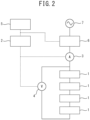
- FIG. 2 illustrates an example of the power storage system.
- the power storage system in FIG. 2 includes: a battery pack containing a plurality of lead storage batteries 1, 1 ⁇ (four in the example in FIG.
- an AC-DC converter 6 performing AC-DC conversion (switching between AC power and DC power) in charging and discharging the battery pack; a current sensor 3 installed between the battery pack and the AC-DC converter 6 and measuring a charge/discharge current in charging and discharging the battery pack; a voltage sensor 4 measuring the voltage of the battery pack; a power storage state monitoring device 2 receiving measurement data transmitted from the current sensor 3 and the voltage sensor 4 and implementing state determination and alarm determination of the battery pack based on the received measurement data; and an energy management system 5 receiving power storage state information transmitted by the power storage state monitoring device 2 based on the implemented state determination and alarm determination and determining whether the charge or the discharge of the battery pack is implemented based on the received power storage state information.
- the energy management system 5 determines whether the charge or the discharge of the battery pack is implemented based on the power storage state information received from the power storage state monitoring device 2, and sends a signal instructing the implementation of the charge or the discharge to the AC-DC converter 6.
- the AC-DC converter 6 converts DC power discharged from the battery pack into AC power and outputs the AC power to a commercial power system 7.
- the AC-DC converter 6 converts AC power input from the commercial power system 7 into DC power to charge the battery pack.
- the number of the lead storage batteries 1 connected in series is determined by the input voltage range of the AC-DC converter 6.
- the thickness of the lead layer for positive electrode 101 is set to 0.5 mm or less in this embodiment.
- the lead layer for positive electrode 101 is formed of a lead alloy satisfying the following two conditions A and B such that a problem with growth is less likely to occur even with such a thickness.
- a lead alloy contains 0.4% by mass or more and 2% by mass or less of tin (Sn) and 0.004% by mass or less of bismuth (Bi), with the balance being lead (Pb) and inevitable impurities or a lead alloy contains 0.4% by mass or more and 2% by mass or less of tin and 0.004% by mass or less of bismuth and further contains at least one of 0.1% by mass or less of calcium and 0.1% by mass or less of silver with the balance being lead and inevitable impurities.
- the lead layer for positive electrode 101 is formed of the above-described lead alloy, and therefore the battery capacity is high and the electrode growth is less likely to occur. Further, an electrode formed of the above-described lead alloy is used for the lead layer for positive electrode 101, and therefore the effects that the lead storage battery 1 and the power storage system have a high battery capacity and the electrode growth is less likely to occur are exhibited. These effects are described in detail.
- the adhesion between the lead layer for positive electrode 101 and the active material layer for positive electrode 103 formed of the lead alloy is improved. Further, when calcium is compounded in the lead alloy, the crystal grains of the lead alloy become fine. Further, when silver is compounded in the lead alloy, the crystal grains of the lead alloy become fine. Therefore, when the lead alloy contains tin and at least one of calcium and silver, the effects that the strength of the lead alloy is increased and the lead alloy is less likely to deform are exhibited.
- the tin content is more preferably 0.7% by mass or more, more preferably 1.0% by mass or more, particularly preferably 1.3% by mass or more, and most preferably 1.6% by mass or more.
- the amount of the Cube orientation ⁇ 001 ⁇ ⁇ 100> in the crystal structure of the lead alloy tends to be small.
- the calcium content is more preferably 0.07% by mass or less, still more preferably 0.04% by mass or less, and particularly preferably 0.02% by mass or less to further improve the corrosion resistance of the lead alloy.
- the silver content is more preferably 0.03% by mass or less to suppress the separation of the silver phase and improve the corrosion resistance of the lead alloy.
- Calcium and silver may be positively added to the lead alloy. However, even when calcium and silver are not positively added, calcium and silver are sometimes included as inevitable impurities due to mixing from bare metals or the like. The maximum amount of both calcium and silver that can be contained as the inevitable impurities is 0.012% by mass.
- the formability of the lead alloy by rolling or the like tends to decrease. More specifically, bismuth is one of the impurities that are preferably not contained as much as possible in the lead alloy of this embodiment. Therefore, the bismuth content in the lead alloy needs to be 0.004% by mass or less and is most preferably 0% by mass. However, considering the cost of the lead alloy, the bismuth content is preferably 0.0004% by mass or more.
- the lead alloy sometimes contains elements other than lead, tin, calcium, silver, and bismuth.
- the elements are impurities inevitably contained in the lead alloy.
- the total content of the elements other than lead, tin, calcium, silver, and bismuth in the lead alloy is preferably 0.01% by mass or less and most preferably 0% by mass.
- the lead alloy of this embodiment forming the lead layer for positive electrode is the lead alloy containing 0.4% by mass or more and 2% by mass or less of tin and 0.004% by mass or less of bismuth, with the balance being lead and inevitable impurities or the lead alloy containing 0.4% by mass or more and 2% by mass or less of tin and 0.004% by mass or less of bismuth and further containing at least one of 0.1% by mass or less of calcium and 0.1% by mass or less of silver, with the balance being lead and inevitable impurities.
- the lead alloy of this embodiment preferably does not contain bismuth as impurities. However, when bismuth is contained, the content needs to be 0.004% by mass or less.
- the total content of the elements is preferably 0.01% by mass or less.
- the lead layer for positive electrode formed of the lead alloy with a large amount of the Cube orientation ⁇ 001 ⁇ ⁇ 100> is reduced in thickness to increase the amount of the active material on the surface, the electrode growth is likely to occur accompanying the volume expansion of the lead oxide generated by the corrosion of the lead layer for positive electrode.
- the lead alloy of this embodiment has a small amount of the Cube orientation ⁇ 001 ⁇ ⁇ 100> in the crystal structure, and therefore the resistance against the elastic deformation is larger (i.e., Young's modulus is higher), so that the elastic deformation becomes less likely to occur. Further, the lead alloy is likely to plastic deform (i.e., the crystal slip deformation amount is large) and is likely to work harden, and therefore the deformation resistance increases when work hardening is performed.
- the lead layer for positive electrode formed of the lead alloy of this embodiment having a small amount of the Cube orientation ⁇ 001 ⁇ ⁇ 100> is less likely to cause the electrode growth accompanying the volume expansion of lead oxide generated by the corrosion of the lead layer for positive electrode, even when the thickness is reduced to 0.5 mm or less.
- the disconnection in an electric joint part between a positive electrode and a negative electrode is less likely to occur or a reduction in battery performance due to the separation of the active material from the lead layer for positive electrode is less likely to occur. Therefore, the use of the positive electrode for lead storage battery containing the lead layer for positive electrode formed of the lead alloy of this embodiment enables the manufacture of a lead storage battery having a high battery capacity and less likely to cause the electrode growth.
- the thickness can be reduced, and therefore the battery capacity can be correspondingly increased.
- a positive electrode has been conventionally constituted by applying a 1 mm thick active material to a 1 mm thick lead layer for positive electrode
- a positive electrode is constituted by applying a 1.8 mm thick active material to a 0.2 mm thick lead layer for positive electrode
- the amount of the active material increases by 1.8 times, and therefore the battery capacity can be increased by about 1.8 times that in a conventional lead storage battery.
- the bipolar lead storage battery when the bipolar lead storage battery is adopted as the lead storage battery, the bipolar lead storage battery can be used at a higher C-rate than that in a conventional lead storage battery with a low internal resistance because the bipolar lead storage battery has high internal resistance. This can reduce the size of the lead storage battery.
- the size of lead storage battery is small, the size of containers or the like can be reduced in a case of applying the lead storage battery to industrial batteries. Therefore, when the lead storage battery is buried underground, for example, the advantage is particularly large.
- the lead storage battery is used for mobilities, such as automobiles, the weight of automobiles and the like can be reduced, which leads to an improvement of fuel efficiency and also enables a reduction in space in which the lead storage battery is mounted in automobiles and the like.
- the lead layer for positive electrode can be reduced in thickness, and therefore the lead storage battery can be reduced in weight. This can facilitate the installation work of the lead storage battery.
- the thickness of the lead layer for positive electrode 101 is set to 0.37 mm or less and more preferably set to 0.25 mm or less, the effect of the present invention that the deterioration of the battery performance is prevented while having the high battery capacity is more likely to be exhibited.
- the electrode for lead storage battery 130 and the lead storage battery 1 of this embodiment even when the lead layer for positive electrode is thinly constituted, the control of the crystal structure of the lead alloy suppresses the corrosion of the lead layer for positive electrode 101, so that the problem of the growth is also solved, and therefore the deterioration of the battery performance can be prevented.
- the thickness of the lead layer for positive electrode By reducing the thickness of the lead layer for positive electrode, the volume inside the battery can be effectively used, and therefore the battery capacity can be increased.
- the amount of the Cube orientation ⁇ 001 ⁇ ⁇ 100> in the crystal structure of the lead alloy is evaluated by the diffraction intensity of the Cube orientation ⁇ 001 ⁇ ⁇ 100> in a pole figure created by analyzing the surface of the lead alloy by the X-ray diffraction method.
- the amount of the random orientation in a pure lead powder is evaluated by the diffraction intensity of the random orientation in a pole figure created by analyzing the surface of the pure lead powder by the X-ray diffraction method.
- a ratio between the diffraction intensity of the Cube orientation ⁇ 001 ⁇ ⁇ 100> of the lead alloy and the diffraction intensity of the random orientation of the pure lead is calculated.
- the diffraction intensity of the cube orientation ⁇ 001 ⁇ ⁇ 100> in the pole figure created by analyzing the surface of the lead alloy by the X-ray diffraction method needs to be 4 times or less, preferably 1.7 times or less, and more preferably 1.4 times or less the diffraction intensity of the random orientation in the pole figure created by analyzing the pure lead powder by the X-ray diffraction method.
- the following description describes a method for controlling the crystal structure by rolling as an example of a method for controlling the crystal structure in the lead alloy of this embodiment (method for reducing the amount of the Cube orientation ⁇ 001 ⁇ ⁇ 100>).
- the rolling performed under the following rolling conditions is effective for achieving the state where the diffraction intensity of the cube orientation ⁇ 001 ⁇ ⁇ 100> in the pole figure created by suppressing the formation of the cube orientation ⁇ 001 ⁇ ⁇ 100> and analyzing the surface of the lead alloy by the X-ray diffraction method is 4 times or less the diffraction intensity of the random orientation in the pole figure created by analyzing the surface of a pure lead powder by the X-ray diffraction method.
- the rolling speed in the rolling is preferably set to 10 m/min or more and 100 m/min or less and more preferably set to 30 m/min or more and 80 m/min or less.
- a surface coating may be provided in a rolling roll to suppress the adhesion between the rolling roll and the lead alloy.
- the surface coating include fluorine coating and diamond-like carbon coating.
- a lubricant may be used to suppress the adhesion between the rolling roll and the lead alloy. When the rolling is performed in a state where the lubricant is arranged between the rolling roll and the lead alloy, the adhesion between the rolling roll and the lead alloy can be suppressed.
- the lubricant include those obtained by adding dibutyl ether to a low-viscosity mineral oil and those obtained by adding propionic acid to a low-viscosity mineral oil.
- a bipolar electrode for bipolar lead storage battery was produced using the rolled foil of each of Examples 1 to 9 and Comparative Examples 1 to 3 as the lead layer for positive electrode. Then, a bipolar lead storage battery was manufactured using the electrode.
- the structures of the electrodes and the bipolar lead storage battery are almost the same as those illustrated in FIG. 1 .
- An active material forming the active material layer for positive electrode is lead dioxide.
- the thickness of the active material layer for positive electrode is 1.4 mm.
- An active material forming the active material layer for negative electrode is lead.
- the thickness of the active material layer for negative electrode is 1.4 mm.
- a charge/discharge cycle test in which charge and discharge were repeated was implemented to the manufactured bipolar lead storage batteries.
- the charge/discharge C-rate was set to 0.2 C.
- the number of the charge/discharge cycles was set to 1000 cycles.
- the lead storage battery in which the battery capacity measured after the completion of the charge/discharge cycle test was 90% or more of the initial battery capacity measured before the implementation of the charge/discharge cycle test was determined to be a lead storage battery less likely to cause the electrode growth, which was indicated as "OK" in Table 1.
- the lead storage battery in which the battery capacity measured after the completion of the charge/discharge cycle test was less than 90% of the initial battery capacity measured before the implementation of the charge/discharge cycle test was determined to be a lead storage battery likely to cause the electrode growth, which was indicated as "NG" in Table 1.
Landscapes
- Chemical & Material Sciences (AREA)
- Chemical Kinetics & Catalysis (AREA)
- Electrochemistry (AREA)
- General Chemical & Material Sciences (AREA)
- Engineering & Computer Science (AREA)
- Materials Engineering (AREA)
- Manufacturing & Machinery (AREA)
- Metallurgy (AREA)
- Mechanical Engineering (AREA)
- Organic Chemistry (AREA)
- Physics & Mathematics (AREA)
- Thermal Sciences (AREA)
- Crystallography & Structural Chemistry (AREA)
- Inorganic Chemistry (AREA)
- Cell Electrode Carriers And Collectors (AREA)
- Battery Electrode And Active Subsutance (AREA)
- Secondary Cells (AREA)
Abstract
Description
- The present invention relates to a lead alloy, a positive electrode for lead storage battery, a lead storage battery, and a power storage system.
- A positive electrode of a lead storage battery includes a lead layer for positive electrode formed of a lead alloy and an active material arranged on the surface of the lead layer for positive electrode. Conventional positive electrodes for lead storage batteries (see, for example, PTL 1) have been formed of well-known lead and lead alloys.
- PTL 1:
WO 2013/073420 - However, when it has been attempted to reduce the thickness of the lead layer for positive electrode to efficiently use the internal volume of the battery, the growth of the lead layer for positive electrode is likely to occur accompanying the volume expansion of lead oxide generated by corrosion due to the lack of strength of the lead layer for positive electrode. This has posed a risk of causing the disconnection in an electric joint part between a positive electrode and a negative electrode or causing a reduction in battery performance due to the separation of the active material from the lead layer for positive electrode.
- Therefore, it is an object of the present invention to provide a lead alloy capable of making the growth of the lead layer for positive electrode less likely to occur even when the thickness is reduced, a positive electrode for lead storage battery formed of the lead alloy, a lead storage battery which contains the positive electrode for lead storage battery and in which a reduction in battery performance is prevented while having a high battery capacity, and a power storage system.
- A lead alloy according to one aspect of the present invention contains: 0.4% by mass or more and 2% by mass or less of tin and 0.004% by mass or less of bismuth, with the balance being lead and inevitable impurities, in which the diffraction intensity of a cube orientation {001} <100> in a pole figure created by analyzing the surface by an X-ray diffraction method is 4 times or less the diffraction intensity of a random orientation in a pole figure created by analyzing a pure lead powder by the X-ray diffraction method.
- A lead alloy according to a different aspect of the present invention contains: 0.4% by mass or more and 2% by mass or less of tin and 0.004% by mass or less of bismuth; and further at least one of 0.1% by mass or less of calcium and 0.1% by mass or less of silver, with the balance being lead and inevitable impurities, in which the diffraction intensity of a cube orientation {001} <100> in a pole figure created by analyzing the surface by an X-ray diffraction method is 4 times or less the diffraction intensity of a random orientation in a pole figure created by analyzing a pure lead powder by the X-ray diffraction method.
- A positive electrode for lead storage battery according to a further different aspect of the present invention includes: a lead layer for positive electrode formed of the lead alloy according to the one aspect or the different aspect; and an active material arranged on the surface of the lead layer for positive electrode, in which the thickness of the lead layer for positive electrode is 0.5 mm or less.
- A lead storage battery according to a still further different aspect of the present invention includes: the positive electrode for lead storage battery according to the still further different aspect.
- A power storage system according to a yet still further different aspect of the present invention includes: the lead storage battery according to the still further different aspect, the power storage system being configured to store power in the lead storage battery.
- The present invention can provide a lead alloy capable of making the growth of the lead layer for positive electrode less likely to occur even when the thickness is reduced, a positive electrode for lead storage battery formed of the lead alloy, a lead storage battery which contains the positive electrode for lead storage battery and in which a deterioration of the battery performance is prevented while having a high battery capacity, and a power storage system.
-
-
FIG. 1 is a cross-sectional view for explaining the structure of a bipolar lead storage battery, which is one embodiment of a lead storage battery according to the present invention; and -
FIG. 2 is a view for explaining one embodiment of a power storage system according to the present invention. - One embodiment of the present invention will be described. This embodiment describes one example of the present invention. Further, this embodiment can be variously altered or modified and embodiments obtained by such alternations or modifications may also be included in the present invention.
- The structure of a
lead storage battery 1 according to one embodiment of the present invention is described with reference toFIG. 1 . Thelead storage battery 1 illustrated inFIG. 1 is a bipolar lead storage battery and includes: a first plate unit in which anegative electrode 110 is fixed to a flat plate-likefirst plate 11; a second plate unit in which anelectrolytic layer 105 is fixed to a frame plate-likesecond plate 12; a third plate unit in which apositive electrode 120, asubstrate 111, and thenegative electrode 110 are fixed in order to a frame plate-likethird plate 13; and a fourth plate unit in which thepositive electrode 120 is fixed to a flat plate-likefourth plate 14, and has a substantially rectangular shape by combining the first plate unit, the second plate unit, the third plate unit, and the fourth plate unit with each other. - A
negative electrode terminal 107 is fixed to thefirst plate 11 in a state of being electrically connected to thenegative electrode 110 fixed to thefirst plate 11. - A
positive electrode terminal 108 is fixed to thefourth plate 14 in a state of being electrically connected to thepositive electrode 120 fixed to thefourth plate 14. - The second plate unit and the third plate unit can be alternately provided in any number of stages according to a desired power storage capacity.
- The first to
fourth plates substrate 111 are formed of a well-known molded resin, for example. - The
electrolytic layer 105 contains a glass fiber mat impregnated with an electrolytic solution, such as sulfuric acid, or the like, for example. - The
negative electrode 110 contains a lead layer fornegative electrode 102 containing a well-known lead foil and an active material layer fornegative electrode 104, for example. - The
positive electrode 120 contains a lead layer forpositive electrode 101 containing a foil of a lead alloy of this embodiment described later and an active material layer forpositive electrode 103. - The
positive electrode 120 and thenegative electrode 110 are separately fixed to the front surface and the back surface of thesubstrate 111 and are electrically connected by an appropriate method. Alternatively, thepositive electrode 120 and thenegative electrode 110 may be separately fixed to one surface of each of the twosubstrates 111, and may be fixed in a state of electrically connecting the other surfaces. - The
plates 11 to 14 are fixed to each other by an appropriate method such that the inside is hermetically sealed to prevent the outflow of an electrolyte. - In the
lead storage battery 1 of this embodiment having such a configuration, thesubstrate 111, the lead layer forpositive electrode 101, the active material layer forpositive electrode 103, the lead layer fornegative electrode 102, and the active material layer fornegative electrode 104 constitute abipolar electrode 130, which is an electrode for lead storage battery. The bipolar electrode is an electrode in which a single electrode functions as both a positive electrode and a negative electrode. - The
lead storage battery 1 of this embodiment has a battery configuration such that a plurality of cells is alternately stacked and assembled, so that the cells are connected in series, the cells each being obtained by interposing theelectrolytic layer 105 between thepositive electrode 120 having the active material layer forpositive electrode 103 and thenegative electrode 110 having the active material layer fornegative electrode 104. - This embodiment describes the bipolar lead storage battery including the bipolar electrode in which a single electrode functions as both a positive electrode and a negative electrode as an example of the lead storage battery. However, the lead storage battery of this embodiment may be a lead storage battery which separately includes an electrode having a positive electrode function and an electrode having a negative electrode function, and in which both a positive electrode and a negative electrode, which are separate bodies, are alternately arranged.
- A power storage system can be constituted using the
lead storage battery 1 of this embodiment illustrated inFIG. 1 .FIG. 2 illustrates an example of the power storage system. The power storage system inFIG. 2 includes: a battery pack containing a plurality oflead storage batteries FIG. 2 ) connected in series; an AC-DC converter 6 performing AC-DC conversion (switching between AC power and DC power) in charging and discharging the battery pack; a current sensor 3 installed between the battery pack and the AC-DC converter 6 and measuring a charge/discharge current in charging and discharging the battery pack; avoltage sensor 4 measuring the voltage of the battery pack; a power storagestate monitoring device 2 receiving measurement data transmitted from the current sensor 3 and thevoltage sensor 4 and implementing state determination and alarm determination of the battery pack based on the received measurement data; and anenergy management system 5 receiving power storage state information transmitted by the power storagestate monitoring device 2 based on the implemented state determination and alarm determination and determining whether the charge or the discharge of the battery pack is implemented based on the received power storage state information. - The
energy management system 5 determines whether the charge or the discharge of the battery pack is implemented based on the power storage state information received from the power storagestate monitoring device 2, and sends a signal instructing the implementation of the charge or the discharge to the AC-DC converter 6. When receiving the signal instructing the implementation of the discharge, the AC-DC converter 6 converts DC power discharged from the battery pack into AC power and outputs the AC power to a commercial power system 7. On the other hand, when receiving the signal instructing the implementation of the charge, the AC-DC converter 6 converts AC power input from the commercial power system 7 into DC power to charge the battery pack. The number of thelead storage batteries 1 connected in series is determined by the input voltage range of the AC-DC converter 6. - Herein, the thickness of the lead layer for
positive electrode 101 is set to 0.5 mm or less in this embodiment. The lead layer forpositive electrode 101 is formed of a lead alloy satisfying the following two conditions A and B such that a problem with growth is less likely to occur even with such a thickness. - A lead alloy contains 0.4% by mass or more and 2% by mass or less of tin (Sn) and 0.004% by mass or less of bismuth (Bi), with the balance being lead (Pb) and inevitable impurities or a lead alloy contains 0.4% by mass or more and 2% by mass or less of tin and 0.004% by mass or less of bismuth and further contains at least one of 0.1% by mass or less of calcium and 0.1% by mass or less of silver with the balance being lead and inevitable impurities.
(Condition B) The diffraction intensity of a cube orientation {001} <100> in a pole figure created by analyzing the surface of the lead alloy by an X-ray diffraction method is 4 times or less the diffraction intensity of a random orientation in a pole figure created by analyzing the surface of a pure lead (Pb) powder by the X-ray diffraction method. - In the
lead storage battery 1 and the power storage system of this embodiment, the lead layer forpositive electrode 101 is formed of the above-described lead alloy, and therefore the battery capacity is high and the electrode growth is less likely to occur. Further, an electrode formed of the above-described lead alloy is used for the lead layer forpositive electrode 101, and therefore the effects that thelead storage battery 1 and the power storage system have a high battery capacity and the electrode growth is less likely to occur are exhibited. These effects are described in detail. - When tin is compounded in the lead alloy, the adhesion between the lead layer for
positive electrode 101 and the active material layer forpositive electrode 103 formed of the lead alloy is improved. Further, when calcium is compounded in the lead alloy, the crystal grains of the lead alloy become fine. Further, when silver is compounded in the lead alloy, the crystal grains of the lead alloy become fine. Therefore, when the lead alloy contains tin and at least one of calcium and silver, the effects that the strength of the lead alloy is increased and the lead alloy is less likely to deform are exhibited. - The tin content is more preferably 0.7% by mass or more, more preferably 1.0% by mass or more, particularly preferably 1.3% by mass or more, and most preferably 1.6% by mass or more. When the tin content is in such a range, the amount of the Cube orientation {001} <100> in the crystal structure of the lead alloy tends to be small.
- The calcium content is more preferably 0.07% by mass or less, still more preferably 0.04% by mass or less, and particularly preferably 0.02% by mass or less to further improve the corrosion resistance of the lead alloy.
- The silver content is more preferably 0.03% by mass or less to suppress the separation of the silver phase and improve the corrosion resistance of the lead alloy.
- Calcium and silver may be positively added to the lead alloy. However, even when calcium and silver are not positively added, calcium and silver are sometimes included as inevitable impurities due to mixing from bare metals or the like. The maximum amount of both calcium and silver that can be contained as the inevitable impurities is 0.012% by mass.
- On the other hand, when bismuth is contained in the lead alloy, the formability of the lead alloy by rolling or the like tends to decrease. More specifically, bismuth is one of the impurities that are preferably not contained as much as possible in the lead alloy of this embodiment. Therefore, the bismuth content in the lead alloy needs to be 0.004% by mass or less and is most preferably 0% by mass. However, considering the cost of the lead alloy, the bismuth content is preferably 0.0004% by mass or more.
- On the other hand, the lead alloy sometimes contains elements other than lead, tin, calcium, silver, and bismuth. The elements are impurities inevitably contained in the lead alloy. The total content of the elements other than lead, tin, calcium, silver, and bismuth in the lead alloy is preferably 0.01% by mass or less and most preferably 0% by mass.
- As described above, the lead alloy of this embodiment forming the lead layer for positive electrode is the lead alloy containing 0.4% by mass or more and 2% by mass or less of tin and 0.004% by mass or less of bismuth, with the balance being lead and inevitable impurities or the lead alloy containing 0.4% by mass or more and 2% by mass or less of tin and 0.004% by mass or less of bismuth and further containing at least one of 0.1% by mass or less of calcium and 0.1% by mass or less of silver, with the balance being lead and inevitable impurities. The lead alloy of this embodiment preferably does not contain bismuth as impurities. However, when bismuth is contained, the content needs to be 0.004% by mass or less. When the elements other than lead, tin, calcium, silver, and bismuth are contained as inevitable impurities in the lead alloy of this embodiment, the total content of the elements is preferably 0.01% by mass or less.
- When the amount of the Cube orientation {001} <100> in the crystal structure of the lead alloy is large, the resistance against elastic deformation decreases, so that the elastic deformation is likely to occur, and the lead alloy is less likely to plastic deform (i.e., crystal slip deformation amount is small) and is less likely to work harden. Therefore, when the lead layer for positive electrode formed of the lead alloy with a large amount of the Cube orientation {001} <100> is reduced in thickness to increase the amount of the active material on the surface, the electrode growth is likely to occur accompanying the volume expansion of the lead oxide generated by the corrosion of the lead layer for positive electrode.
- The lead alloy of this embodiment has a small amount of the Cube orientation {001} <100> in the crystal structure, and therefore the resistance against the elastic deformation is larger (i.e., Young's modulus is higher), so that the elastic deformation becomes less likely to occur. Further, the lead alloy is likely to plastic deform (i.e., the crystal slip deformation amount is large) and is likely to work harden, and therefore the deformation resistance increases when work hardening is performed.
- Therefore, the lead layer for positive electrode formed of the lead alloy of this embodiment having a small amount of the Cube orientation {001} <100> is less likely to cause the electrode growth accompanying the volume expansion of lead oxide generated by the corrosion of the lead layer for positive electrode, even when the thickness is reduced to 0.5 mm or less. As a result, the disconnection in an electric joint part between a positive electrode and a negative electrode is less likely to occur or a reduction in battery performance due to the separation of the active material from the lead layer for positive electrode is less likely to occur. Therefore, the use of the positive electrode for lead storage battery containing the lead layer for positive electrode formed of the lead alloy of this embodiment enables the manufacture of a lead storage battery having a high battery capacity and less likely to cause the electrode growth.
- Further, when the lead layer for
positive electrode 101 is formed using the lead alloy of this embodiment, the thickness can be reduced, and therefore the battery capacity can be correspondingly increased. For example, supposing that a positive electrode has been conventionally constituted by applying a 1 mm thick active material to a 1 mm thick lead layer for positive electrode, when a positive electrode is constituted by applying a 1.8 mm thick active material to a 0.2 mm thick lead layer for positive electrode, the amount of the active material increases by 1.8 times, and therefore the battery capacity can be increased by about 1.8 times that in a conventional lead storage battery. - Further, when the bipolar lead storage battery is adopted as the lead storage battery, the bipolar lead storage battery can be used at a higher C-rate than that in a conventional lead storage battery with a low internal resistance because the bipolar lead storage battery has high internal resistance. This can reduce the size of the lead storage battery.
- When the size of lead storage battery is small, the size of containers or the like can be reduced in a case of applying the lead storage battery to industrial batteries. Therefore, when the lead storage battery is buried underground, for example, the advantage is particularly large. When the lead storage battery is used for mobilities, such as automobiles, the weight of automobiles and the like can be reduced, which leads to an improvement of fuel efficiency and also enables a reduction in space in which the lead storage battery is mounted in automobiles and the like.
- Further, the lead layer for positive electrode can be reduced in thickness, and therefore the lead storage battery can be reduced in weight. This can facilitate the installation work of the lead storage battery.
- When the thickness of the lead layer for
positive electrode 101 is set to 0.37 mm or less and more preferably set to 0.25 mm or less, the effect of the present invention that the deterioration of the battery performance is prevented while having the high battery capacity is more likely to be exhibited. - As described above, according to the electrode for
lead storage battery 130 and thelead storage battery 1 of this embodiment, even when the lead layer for positive electrode is thinly constituted, the control of the crystal structure of the lead alloy suppresses the corrosion of the lead layer forpositive electrode 101, so that the problem of the growth is also solved, and therefore the deterioration of the battery performance can be prevented. By reducing the thickness of the lead layer for positive electrode, the volume inside the battery can be effectively used, and therefore the battery capacity can be increased. - The amount of the Cube orientation {001} <100> in the crystal structure of the lead alloy is evaluated by the diffraction intensity of the Cube orientation {001} <100> in a pole figure created by analyzing the surface of the lead alloy by the X-ray diffraction method. Then, the amount of the random orientation in a pure lead powder is evaluated by the diffraction intensity of the random orientation in a pole figure created by analyzing the surface of the pure lead powder by the X-ray diffraction method. A ratio between the diffraction intensity of the Cube orientation {001} <100> of the lead alloy and the diffraction intensity of the random orientation of the pure lead is calculated.
- In this embodiment, the diffraction intensity of the cube orientation {001} <100> in the pole figure created by analyzing the surface of the lead alloy by the X-ray diffraction method needs to be 4 times or less, preferably 1.7 times or less, and more preferably 1.4 times or less the diffraction intensity of the random orientation in the pole figure created by analyzing the pure lead powder by the X-ray diffraction method.
- The following description describes a method for controlling the crystal structure by rolling as an example of a method for controlling the crystal structure in the lead alloy of this embodiment (method for reducing the amount of the Cube orientation {001} <100>).
- Conventionally, when a lead layer for positive electrode is manufactured by rolling a lead alloy, the adhesion between a rolling roll and the lead alloy has been relatively likely to occur. Therefore, the rolling has been performed by a plurality of times of rolling reduction after reducing the draft in one pass or the rolling has been performed by setting the rolling speed to a low speed to reduce the heat generation by working in many cases. However, as a result of an examination by the present inventors, it was found that the Cube orientation {001} <100> is likely to be formed when the rolling is performed under these conditions.
- Thus, as a result of an examination by the present inventors, it was found that the rolling performed under the following rolling conditions is effective for achieving the state where the diffraction intensity of the cube orientation {001} <100> in the pole figure created by suppressing the formation of the cube orientation {001} <100> and analyzing the surface of the lead alloy by the X-ray diffraction method is 4 times or less the diffraction intensity of the random orientation in the pole figure created by analyzing the surface of a pure lead powder by the X-ray diffraction method.
- More specifically, it is preferable to perform the rolling by one rolling reduction with the draft in one pass in the rolling set to 10% or more and 30% or less and it is more preferable to perform the rolling by one rolling reduction with the draft in one pass in the rolling set to 15% or more and 25% or less. The rolling speed in the rolling is preferably set to 10 m/min or more and 100 m/min or less and more preferably set to 30 m/min or more and 80 m/min or less.
- In the rolling, a surface coating may be provided in a rolling roll to suppress the adhesion between the rolling roll and the lead alloy. Examples of the surface coating include fluorine coating and diamond-like carbon coating. Further, in the rolling, a lubricant may be used to suppress the adhesion between the rolling roll and the lead alloy. When the rolling is performed in a state where the lubricant is arranged between the rolling roll and the lead alloy, the adhesion between the rolling roll and the lead alloy can be suppressed. Examples of the lubricant include those obtained by adding dibutyl ether to a low-viscosity mineral oil and those obtained by adding propionic acid to a low-viscosity mineral oil.
- The present invention is more specifically described with reference to Examples and Comparative Examples below.
- 10 mm thick alloy sheets containing lead alloys having the alloy compositions shown in Table 1 were manufactured by melting and casting. The alloy sheets were rolled to produce 0.15 mm or 0.45 mm thick rolled foils. The rolling conditions are as follows. For Examples 1 to 9, the rolling was performed with the draft in one pass set to 20% and the rolling speed set to 40 m/min. For Comparative Examples 1 to 5, the rolling was performed with the draft in one pass set to 5% as before and the rolling speed set to 5 m/min. For Comparative Example 4 and Comparative Example 5, a defect referred to as an edge crack occurred in an edge portion of the sheet during the rolling, and therefore rolled foils were not able to produce.
[Table 1] Alloy composition (% by mass) Draft (%) Foil thickness (mm) Diffraction intensity ratio Battery capacity Sn Ca Ag Bi Pb Ex. 1 1.7 0.09 0 0.002 Balance 20 0.15 1 OK 2 1.4 0.06 0 0.002 Balance 20 0.15 1 OK 3 1.1 0.02 0 0.002 Balance 20 0.15 1 OK 4 1.1 0 0.02 0.002 Balance 20 0.15 2 OK 5 1.4 0 0 0.002 Balance 20 0.15 2 OK 6 1.7 0.02 0.02 0.002 Balance 20 0.15 2 OK 7 0.5 0.01 0.01 0.002 Balance 20 0.15 2 OK 8 0.8 0.015 0.015 0.002 Balance 20 0.45 3 OK 9 1.8 0.015 0.015 0.002 Balance 20 0.45 2 OK Comp. Ex. 1 1.4 0.02 0 0.002 Balance 5 0.15 5 NG 2 1.1 0 0.02 0.002 Balance 5 0.15 7 NG 3 1.4 0 0 0.002 Balance 5 0.15 6 NG 4 1.7 0.09 0 0.010 Balance 5 - - - 5 1.4 0 0 0.010 Balance 5 - - - - Next, the surface (rolled surface) of each of the produced rolled foils of Examples 1 to 9 and Comparative Examples 1 to 3 was analyzed by the X-ray diffraction method, and an (111) X-ray pole figure was created from the results. Then, the diffraction intensity of the Cube orientation {001} <100> in the pole figure was obtained. Further, the surface of a pure lead powder in the random orientation state was analyzed by the X-ray diffraction method, and a pole figure was created from the results. Then, the diffraction intensity of the random orientation in the pole figure was obtained. A diffraction intensity ratio was calculated by dividing the diffraction intensity of the random orientation by the obtained diffraction intensity of the cube orientation {001}
- Next, a bipolar electrode for bipolar lead storage battery was produced using the rolled foil of each of Examples 1 to 9 and Comparative Examples 1 to 3 as the lead layer for positive electrode. Then, a bipolar lead storage battery was manufactured using the electrode. The structures of the electrodes and the bipolar lead storage battery are almost the same as those illustrated in
FIG. 1 . An active material forming the active material layer for positive electrode is lead dioxide. The thickness of the active material layer for positive electrode is 1.4 mm. An active material forming the active material layer for negative electrode is lead. The thickness of the active material layer for negative electrode is 1.4 mm. - A charge/discharge cycle test in which charge and discharge were repeated was implemented to the manufactured bipolar lead storage batteries. The charge/discharge C-rate was set to 0.2 C. The number of the charge/discharge cycles was set to 1000 cycles. The lead storage battery in which the battery capacity measured after the completion of the charge/discharge cycle test was 90% or more of the initial battery capacity measured before the implementation of the charge/discharge cycle test was determined to be a lead storage battery less likely to cause the electrode growth, which was indicated as "OK" in Table 1. The lead storage battery in which the battery capacity measured after the completion of the charge/discharge cycle test was less than 90% of the initial battery capacity measured before the implementation of the charge/discharge cycle test was determined to be a lead storage battery likely to cause the electrode growth, which was indicated as "NG" in Table 1.
- The results shown in Table 1 show that the lead storage batteries of Examples 1 to 9 have a diffraction intensity ratio of 3 or less, and therefore the lead storage batteries are lead storage batteries less likely to cause the electrode growth. In contrast thereto, the results show that the lead storage batteries of Comparative Examples 1 to 3 have a diffraction intensity ratio of more than 3, and therefore the lead storage batteries are lead storage batteries likely to cause the electrode growth.
-
- 1
- lead storage battery
- 101
- lead layer for positive electrode
- 102
- lead layer for negative electrode
- 103
- active material layer for positive electrode
- 104
- active material layer for negative electrode
- 105
- electrolytic layer
- 111
- substrate
Claims (7)
- A lead alloy comprising:0.4% by mass or more and 2% by mass or less of tin and 0.004% by mass or less of bismuth, with a balance being lead and inevitable impurities, whereina diffraction intensity of a cube orientation {001} <100> in a pole figure created by analyzing a surface by an X-ray diffraction method is 4 times or less a diffraction intensity of a random orientation in a pole figure created by analyzing a pure lead powder by the X-ray diffraction method.
- A lead alloy comprising:0.4% by mass or more and 2% by mass or less of tin and 0.004% by mass or less of bismuth and further at least one of 0.1% by mass or less of calcium and 0.1% by mass or less of silver, with a balance being lead and inevitable impurities, whereina diffraction intensity of a cube orientation {001} <100> in a pole figure created by analyzing a surface by an X-ray diffraction method is 4 times or less a diffraction intensity of a random orientation in a pole figure created by analyzing a pure lead powder by the X-ray diffraction method.
- The lead alloy according to claim 1 or 2, wherein a content of the bismuth is 0.0004 % by mass or more and 0.004 % by mass or less.
- A positive electrode for lead storage battery comprising:a lead layer for positive electrode formed of the lead alloy according to any one of claims 1 to 3; andan active material arranged on a surface of the lead layer for positive electrode, whereina thickness of the lead layer for positive electrode is 0.5 mm or less.
- The positive electrode for lead storage battery according to claim 4, the positive electrode is for a bipolar lead storage battery.
- A lead storage battery comprising:
the positive electrode for lead storage battery according to claim 4 or 5. - A power storage system comprising:the lead storage battery according to claim 6,the power storage system being configured to store power in the lead storage battery.
Applications Claiming Priority (2)
| Application Number | Priority Date | Filing Date | Title |
|---|---|---|---|
| JP2020133405 | 2020-08-05 | ||
| PCT/JP2021/028489 WO2022030415A1 (en) | 2020-08-05 | 2021-07-30 | Lead alloy, positive electrode for lead storage battery, lead storage battery, and electricity storage system |
Publications (2)
| Publication Number | Publication Date |
|---|---|
| EP4194573A1 true EP4194573A1 (en) | 2023-06-14 |
| EP4194573A4 EP4194573A4 (en) | 2024-09-11 |
Family
ID=80118058
Family Applications (1)
| Application Number | Title | Priority Date | Filing Date |
|---|---|---|---|
| EP21852353.8A Withdrawn EP4194573A4 (en) | 2020-08-05 | 2021-07-30 | Lead alloy, positive electrode for lead storage battery, lead storage battery, and electricity storage system |
Country Status (7)
| Country | Link |
|---|---|
| US (1) | US20230178712A1 (en) |
| EP (1) | EP4194573A4 (en) |
| JP (1) | JP7296016B2 (en) |
| CN (1) | CN116157545A (en) |
| AU (1) | AU2021322415A1 (en) |
| BR (1) | BR112023001414A2 (en) |
| WO (1) | WO2022030415A1 (en) |
Families Citing this family (2)
| Publication number | Priority date | Publication date | Assignee | Title |
|---|---|---|---|---|
| WO2023149304A1 (en) * | 2022-02-03 | 2023-08-10 | 古河電気工業株式会社 | Lead-acid battery system and lead-acid battery service life estimation method |
| CN118451335A (en) * | 2022-02-03 | 2024-08-06 | 古河电气工业株式会社 | Lead storage battery system and lead storage battery life estimation method |
Family Cites Families (10)
| Publication number | Priority date | Publication date | Assignee | Title |
|---|---|---|---|---|
| JPH0770321B2 (en) * | 1986-12-16 | 1995-07-31 | 松下電器産業株式会社 | Sealed lead acid battery |
| JPH01117272A (en) * | 1987-10-29 | 1989-05-10 | Shin Kobe Electric Mach Co Ltd | Lead-acid battery |
| JP4026257B2 (en) * | 1998-12-21 | 2007-12-26 | 松下電器産業株式会社 | Lead acid battery |
| JP4395751B2 (en) * | 2004-12-17 | 2010-01-13 | 三菱マテリアル株式会社 | Method for producing Pb-Sn-Ca-Al-based lead alloy sheet for storage battery |
| CN1775962A (en) * | 2005-10-11 | 2006-05-24 | 成都理工大学 | Method for improving anticorrosive capacity of grid plate for lead-acid battery |
| JP5087950B2 (en) * | 2007-02-27 | 2012-12-05 | 新神戸電機株式会社 | Lead acid battery |
| US7923155B2 (en) * | 2007-03-20 | 2011-04-12 | Northstar Battery Company, Llc | Lead-tin-silver-bismuth containing alloy for positive grid of lead acid batteries |
| DK2668683T3 (en) * | 2011-05-11 | 2016-03-07 | Gridtential Energy Inc | Improved battery and assembly process |
| CN107112543B (en) * | 2015-01-08 | 2020-05-19 | 株式会社杰士汤浅国际 | Positive electrode grid for lead storage battery, method for manufacturing positive electrode grid for lead storage battery, and lead storage battery |
| JP2019067522A (en) * | 2017-09-28 | 2019-04-25 | 古河電池株式会社 | Method of manufacturing positive electrode lattice body for lead storage battery, positive electrode lattice body for storage battery, and lead storage battery |
-
2021
- 2021-07-30 EP EP21852353.8A patent/EP4194573A4/en not_active Withdrawn
- 2021-07-30 WO PCT/JP2021/028489 patent/WO2022030415A1/en not_active Ceased
- 2021-07-30 JP JP2022541515A patent/JP7296016B2/en active Active
- 2021-07-30 BR BR112023001414A patent/BR112023001414A2/en not_active IP Right Cessation
- 2021-07-30 CN CN202180057881.9A patent/CN116157545A/en active Pending
- 2021-07-30 AU AU2021322415A patent/AU2021322415A1/en not_active Abandoned
-
2023
- 2023-01-31 US US18/162,449 patent/US20230178712A1/en not_active Abandoned
Also Published As
| Publication number | Publication date |
|---|---|
| EP4194573A4 (en) | 2024-09-11 |
| AU2021322415A1 (en) | 2023-03-23 |
| BR112023001414A2 (en) | 2023-02-14 |
| JP7296016B2 (en) | 2023-06-21 |
| JPWO2022030415A1 (en) | 2022-02-10 |
| CN116157545A (en) | 2023-05-23 |
| WO2022030415A1 (en) | 2022-02-10 |
| US20230178712A1 (en) | 2023-06-08 |
Similar Documents
| Publication | Publication Date | Title |
|---|---|---|
| EP2330676B1 (en) | Lead acid storage battery | |
| KR102158241B1 (en) | Electrolytic Copper Foil, Current Collector Comprising The Same, Electrode Comprising The Same, Secondary Battery Comprising The Same, and Method for Manufacturing The Same | |
| EP3059791B1 (en) | Valve-regulated lead-acid battery | |
| EP3473736A1 (en) | Rolled copper foil for negative electrode current collector of secondary battery, negative electrode of secondary battery and secondary battery using the rolled copper, and method for manufacturing rolled copper foil for negative electrode current collector of secondary battery | |
| JP4148175B2 (en) | Lead alloy and lead storage battery using the same | |
| US20230178712A1 (en) | Lead Alloy, Positive Electrode for Lead Storage Battery, Lead Storage Battery, and Power Storage System | |
| JP2004158433A (en) | Substrate for lead storage battery and lead storage battery using the same | |
| JP2023162291A (en) | Lead alloy foil and its manufacturing method, positive electrode for lead-acid batteries, lead-acid batteries, and power storage systems | |
| CN119923739A (en) | Flexible battery | |
| US20230299267A1 (en) | Lead Alloy, Lead Storage Battery Electrode, Lead Storage Battery, and Power Storage System | |
| JP4292666B2 (en) | Sealed lead acid battery | |
| JP5569164B2 (en) | Lead acid battery | |
| JP2003338310A (en) | Lead storage battery | |
| JPWO2009113166A1 (en) | Lead acid battery | |
| JP3099328B2 (en) | Lead storage battery | |
| JP4364054B2 (en) | Lead acid battery | |
| JP3405101B2 (en) | Sealed lead-acid battery | |
| US20230299268A1 (en) | Lead Alloy, Lead Storage Battery Electrode, Lead Storage Battery, and Power Storage System | |
| JP7198890B1 (en) | lead acid battery | |
| JP5600940B2 (en) | Lead battery | |
| WO2000046868A1 (en) | Lead-tin alloy current collectors, batteries made thereof and methods for manufacturing same | |
| CN107408674A (en) | Lead accumulator | |
| JP2002203565A (en) | Sealed lead-acid battery | |
| JPH0237667A (en) | lead acid battery | |
| JPH10302784A (en) | Manufacturing method of paste type positive electrode plate |
Legal Events
| Date | Code | Title | Description |
|---|---|---|---|
| STAA | Information on the status of an ep patent application or granted ep patent |
Free format text: STATUS: THE INTERNATIONAL PUBLICATION HAS BEEN MADE |
|
| PUAI | Public reference made under article 153(3) epc to a published international application that has entered the european phase |
Free format text: ORIGINAL CODE: 0009012 |
|
| STAA | Information on the status of an ep patent application or granted ep patent |
Free format text: STATUS: REQUEST FOR EXAMINATION WAS MADE |
|
| 17P | Request for examination filed |
Effective date: 20230126 |
|
| AK | Designated contracting states |
Kind code of ref document: A1 Designated state(s): AL AT BE BG CH CY CZ DE DK EE ES FI FR GB GR HR HU IE IS IT LI LT LU LV MC MK MT NL NO PL PT RO RS SE SI SK SM TR |
|
| DAV | Request for validation of the european patent (deleted) | ||
| DAX | Request for extension of the european patent (deleted) | ||
| A4 | Supplementary search report drawn up and despatched |
Effective date: 20240814 |
|
| RIC1 | Information provided on ipc code assigned before grant |
Ipc: H01M 4/02 20060101ALI20240808BHEP Ipc: H01M 50/534 20210101ALI20240808BHEP Ipc: H01M 10/06 20060101ALI20240808BHEP Ipc: H01M 4/73 20060101ALI20240808BHEP Ipc: H01M 4/68 20060101ALI20240808BHEP Ipc: H01M 4/66 20060101ALI20240808BHEP Ipc: H01M 4/56 20060101ALI20240808BHEP Ipc: H01M 4/38 20060101ALI20240808BHEP Ipc: H01M 4/20 20060101ALI20240808BHEP Ipc: H01M 4/16 20060101ALI20240808BHEP Ipc: H01M 4/14 20060101ALI20240808BHEP Ipc: C22F 1/12 20060101ALI20240808BHEP Ipc: C22F 1/00 20060101ALI20240808BHEP Ipc: C22C 11/06 20060101AFI20240808BHEP |
|
| STAA | Information on the status of an ep patent application or granted ep patent |
Free format text: STATUS: THE APPLICATION IS DEEMED TO BE WITHDRAWN |
|
| 18D | Application deemed to be withdrawn |
Effective date: 20250304 |