EP4193084B1 - Verfahren zur anzeige einer stellposition eines stellantriebs, anzeigeeinheit für einen stellantrieb und stellantrieb - Google Patents
Verfahren zur anzeige einer stellposition eines stellantriebs, anzeigeeinheit für einen stellantrieb und stellantrieb Download PDFInfo
- Publication number
- EP4193084B1 EP4193084B1 EP21797988.9A EP21797988A EP4193084B1 EP 4193084 B1 EP4193084 B1 EP 4193084B1 EP 21797988 A EP21797988 A EP 21797988A EP 4193084 B1 EP4193084 B1 EP 4193084B1
- Authority
- EP
- European Patent Office
- Prior art keywords
- graphic element
- actuating
- display unit
- actuator
- displayed
- Prior art date
- Legal status (The legal status is an assumption and is not a legal conclusion. Google has not performed a legal analysis and makes no representation as to the accuracy of the status listed.)
- Active
Links
Images

Classifications
-
- F—MECHANICAL ENGINEERING; LIGHTING; HEATING; WEAPONS; BLASTING
- F16—ENGINEERING ELEMENTS AND UNITS; GENERAL MEASURES FOR PRODUCING AND MAINTAINING EFFECTIVE FUNCTIONING OF MACHINES OR INSTALLATIONS; THERMAL INSULATION IN GENERAL
- F16K—VALVES; TAPS; COCKS; ACTUATING-FLOATS; DEVICES FOR VENTING OR AERATING
- F16K37/00—Special means in or on valves or other cut-off apparatus for indicating or recording operation thereof, or for enabling an alarm to be given
- F16K37/0025—Electrical or magnetic means
- F16K37/0041—Electrical or magnetic means for measuring valve parameters
-
- F—MECHANICAL ENGINEERING; LIGHTING; HEATING; WEAPONS; BLASTING
- F16—ENGINEERING ELEMENTS AND UNITS; GENERAL MEASURES FOR PRODUCING AND MAINTAINING EFFECTIVE FUNCTIONING OF MACHINES OR INSTALLATIONS; THERMAL INSULATION IN GENERAL
- F16K—VALVES; TAPS; COCKS; ACTUATING-FLOATS; DEVICES FOR VENTING OR AERATING
- F16K1/00—Lift valves or globe valves, i.e. cut-off apparatus with closure members having at least a component of their opening and closing motion perpendicular to the closing faces
- F16K1/16—Lift valves or globe valves, i.e. cut-off apparatus with closure members having at least a component of their opening and closing motion perpendicular to the closing faces with pivoted closure-members
- F16K1/18—Lift valves or globe valves, i.e. cut-off apparatus with closure members having at least a component of their opening and closing motion perpendicular to the closing faces with pivoted closure-members with pivoted discs or flaps
- F16K1/22—Lift valves or globe valves, i.e. cut-off apparatus with closure members having at least a component of their opening and closing motion perpendicular to the closing faces with pivoted closure-members with pivoted discs or flaps with axis of rotation crossing the valve member, e.g. butterfly valves
-
- F—MECHANICAL ENGINEERING; LIGHTING; HEATING; WEAPONS; BLASTING
- F16—ENGINEERING ELEMENTS AND UNITS; GENERAL MEASURES FOR PRODUCING AND MAINTAINING EFFECTIVE FUNCTIONING OF MACHINES OR INSTALLATIONS; THERMAL INSULATION IN GENERAL
- F16K—VALVES; TAPS; COCKS; ACTUATING-FLOATS; DEVICES FOR VENTING OR AERATING
- F16K37/00—Special means in or on valves or other cut-off apparatus for indicating or recording operation thereof, or for enabling an alarm to be given
- F16K37/0025—Electrical or magnetic means
- F16K37/0033—Electrical or magnetic means using a permanent magnet, e.g. in combination with a reed relays
-
- G—PHYSICS
- G06—COMPUTING OR CALCULATING; COUNTING
- G06T—IMAGE DATA PROCESSING OR GENERATION, IN GENERAL
- G06T3/00—Geometric image transformations in the plane of the image
- G06T3/60—Rotation of whole images or parts thereof
-
- G—PHYSICS
- G09—EDUCATION; CRYPTOGRAPHY; DISPLAY; ADVERTISING; SEALS
- G09F—DISPLAYING; ADVERTISING; SIGNS; LABELS OR NAME-PLATES; SEALS
- G09F9/00—Indicating arrangements for variable information in which the information is built-up on a support by selection or combination of individual elements
- G09F9/30—Indicating arrangements for variable information in which the information is built-up on a support by selection or combination of individual elements in which the desired character or characters are formed by combining individual elements
- G09F9/35—Indicating arrangements for variable information in which the information is built-up on a support by selection or combination of individual elements in which the desired character or characters are formed by combining individual elements being liquid crystals
Definitions
- the invention relates to a method for displaying an actuating position of an actuator, in which a graphic element is displayed on a display unit corresponding to the actuating position.
- the invention further relates to a display unit for an actuator and a corresponding actuator.
- Such methods and display units are known for actuators and serve to display the current position of a valve that is actuated by the actuator.
- linear bars have been proposed, the degree of filling of which indicates a progressive closing or opening of a valve.
- a valve with an opening and closing control system in which a valve installed in a liquid-flowing pipe is displayed on an external portable terminal, whereby a user can easily check the opening and closing state of the valve.
- a valve device which has a visual display mechanism for indicating a valve position, the display mechanism being non-invasive.
- the valve position display can be linked to a light device.
- the display mechanism for determining the position of the valve can be forwarded to a closure detection module.
- JP 2010 039715 A is a valve control device for controlling a valve in a petrochemical plant, for example an FCC system or an RFCC system.
- valve control device which can remotely query the status of an actuator for adjusting the valve opening and closing via Internet communication and wherein an adjustment can be carried out remotely.
- the invention is based on the object of improving the operating properties of an actuator.
- the features of claim 1 are provided according to the invention.
- the graphic element for displaying the setting position is displayed rotated about an axis. This creates a display option that requires minimal space on a display unit. It is also easy to determine the current position of a connected valve on a fitting, as a rotary movement appears more natural than a linear representation.
- the open position or open position and the closed position or closed position can also be easily detected and displayed using further, stationary and time-constant markings.
- the graphic element is loaded into a volatile memory before display. This means that the graphic element can be easily processed to display the current position. In addition, graphic elements do not have to be kept in memory for each position in order to reproduce a position.
- a rotated position of the graphic element corresponding to the positioning position is generated in the volatile memory. This means that the graphical element can be rotated using simple routines that require as little computing capacity as possible.
- the display is carried out on a liquid crystal screen.
- Liquid crystal displays have the advantage of a particularly wide temperature range for proper operation.
- an available adjustment path is mapped to a rotation angle of 90°. Ambiguities that can arise if the graphic element assumes the same or an indistinguishable position several times during an adjustment along the available travel range can be avoided.
- the graphic element has 180° symmetry. This creates redundancy that can be used advantageously when the direction of a closing movement of a connected valve is reversed.
- a rotation angle of the graphic element either the function of an end position or an initial position during a closing movement or an opening movement, so that For the viewer, the open position and the closed position can remain at the same angle of rotation, even if the direction of rotation of the individual movements is reversed.
- the display is carried out automatically with an offset of 90° or with a reverse direction of rotation of the graphic element. This means that the actuator can be connected to different fittings with opposite closing behavior without the viewer having to get used to the display.
- This embodiment can be advantageously combined with a representation of the available adjustment path at a 90° rotation angle on the graphic element.
- the advantage here is that the adjacent 90° rotation angles can be used for an opposite closing movement.
- this embodiment can be advantageously combined with a 180° symmetry of the graphic element.
- a position of the graphic element at 0° is indistinguishable from that at 180° and can be used to indicate a state of the valve regardless of the orientation of the closing direction.
- a further graphic element is displayed, with which a movement beyond an end position of the adjustment path can be displayed. This means that additional information about the actual condition of the valve can be displayed.
- the movement can be displayed with a different resolution.
- the resolution can be coarser in order to be able to clearly see any overshooting (e.g. due to inertia or lag).
- the movement can be displayed as a current torque of the actuator.
- Exceeding can therefore be indicated indirectly by exceeding an impact that leads to an end position being exceeded via an elastic deformation.
- the features of the subordinate claim directed to a display unit for an actuator are provided according to the invention.
- means for carrying out a method according to the invention in particular as described above or according to one of the claims directed to a method, are designed.
- the display unit can be further characterized by a microprocessor and a volatile memory, wherein the microprocessor is set up to calculate a rotated image of a graphic element depending on a current positioning position of the actuator and to provide the rotated graphic element in the volatile memory, in particular for a display on the display unit.
- a preferred application of the invention sees an actuator with a display unit according to the invention for an actuator, in particular as described above or according to one of the claims directed to a display unit for an actuator, and / or with means for carrying out a method according to the invention, in particular as described above or according to one of the claims directed to a method.
- Fig. 6 shows a highly schematic representation of an actuator 1.
- the actuator 1 has a motor-driven output shaft 2, to which a valve 3 of a fitting (not shown) is connected in a manner known per se.
- the valve 3 can be adjusted between an open position, in which a tube 4 is fluidically conductive, and a closed position, in which the tube 4 blocks fluidically, by actuating the output shaft 2.
- a rotational position of the output shaft 2 can be detected via a sensor 5, for example an encoder, as an absolute value and/or as an incremental value.
- the actuator 1 has a display unit 6, the functionality of which is described in more detail below.
- the display unit 6 is designed as a liquid crystal screen (LCD).
- the display unit 6 interacts with the actuator 1, but is designed separately from it.
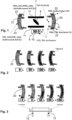
- Fig. 1 shows a possible state of the display unit 6 Fig. 6 .
- a graphic element 7 can be rotated about a (virtual) axis 8 to display a current position of the output shaft 4 or the valve 3.
- the display on the display unit 6 is coupled to the sensor 5.
- an associated numerical value 10 of the position here in percent of the distance already traveled to the closing position, is displayed.
- Fig. 4 shows different positioning of the graphic element 7 between an open position 12 (top left) and a closed position 13 (top right).
- the graphic element 7 is rotated clockwise.
- the sensor 5 was used to determine where the open position 12 and the closed position 13 were. This shows in which direction the graphic element 7 must rotate in order to get from the open position 12 to the closed position 13.
- the bottom line in Figure 4 represents the reverse movement from the closed position 13 to the open position 12.
- the direction of rotation of the movement of the graphic element 7 is reversed.
- valve 3 is constructed in a mirror image, the open position 12 and the closed position 13 must swap positions on the output shaft 4.
- the display unit 6 switches over so that the graphic element 7 rotates counterclockwise in order to come from the open position 12 to the closed position 13.
- the open position 12 and closed position 13 are shown rotated by 90° to each other by mapping the available travel between the end positions to an angular range of 90°.
- a rotation between the open position 12 and the shooting position 13 by 90 ° and the 180 ° rotational symmetry (with respect to the axis 8) of the graphic element enables the end positions of the adjusting movement to remain the same and the coupling of the position of the graphic element 7 the movement of the output shaft 4 can remain unchanged.
- This offset can be determined automatically based on the position of the open position 12 and closed position 13 and/or a direction of travel between them during commissioning.
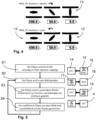
- Fig. 5 shows in a very simplified form how the rotation of the graphic element 7 is carried out.
- a microprocessor 14 loads a representation 15 of the graphic element 7 from a non-volatile memory 16, for example a flash memory.
- the current representation 17 of the graphic element 7 is loaded into a volatile memory 18, here a RAM.
- a calculation step S3 the graphic element 7 is processed using standard commands in the volatile memory 18 until a rotated representation 19 is calculated.
- the angle of rotation results from measurement data that the microprocessor 14 receives from the sensor 5.
- a display step S4 the microprocessor 14 (or another graphic processor) controls the display unit so that - preferably in a defined area - the graphic element 7 is displayed in the position in which it is stored in the volatile memory 18.
- step S1 The process then continues in step S1.
- T closed position 13 with - exemplary - switch-off type torque
- L open position 12 with - exemplary - switch-off type position
- a number of partial markings 21 are colored corresponding to the travel distance.
- Figure 3 shows a full movement from an underflow (left), i.e. falling below a lowest position, via the closed position 13 (2nd picture from the left) and the open position 12 (2nd picture from the right) into an overflow (right).
- Another graphic element 23 can alternatively indicate that the maximum switch-off torque has been exceeded.
- the torque on the output shaft 4 is displayed by coloring a corresponding number of partial markings.
- a threshold value here, for example, 80 Nm
- separate partial markings 22 are colored so that the user recognizes that a moment is approaching the end position.
- Figure 2 shows a (torqueless) rest position (left), the movement along the travel with a low torque (2nd picture from the left), reaching the maximum switch-off torque (2nd picture from the right) and exceeding the switch-off torque (right).
- the invention thus relates to a display unit 6, which is set up to display a current positioning position of an actuator 1 coupled to a valve 3 of a fitting by means of a variable graphic element 7, the graphic element 7 responding to a sensor 5 with which the current positioning position is determined, is shown rotated by a corresponding angle of rotation.
Landscapes
- Engineering & Computer Science (AREA)
- General Engineering & Computer Science (AREA)
- Mechanical Engineering (AREA)
- Physics & Mathematics (AREA)
- General Physics & Mathematics (AREA)
- Theoretical Computer Science (AREA)
- Chemical & Material Sciences (AREA)
- Crystallography & Structural Chemistry (AREA)
- Indication Of The Valve Opening Or Closing Status (AREA)
Description
- Die Erfindung betrifft ein Verfahren zur Anzeige einer Stellposition eines Stellantriebs, bei dem ein grafisches Element an einer Anzeigeeinheit korrespondierend zur Stellposition angezeigt wird.
- Die Erfindung betrifft weiter eine Anzeigeeinheit für einen Stellantrieb und einen korrespondierenden Stellantrieb.
- Derartige Verfahren und Anzeigeeinheiten sind bei Stellantrieben bekannt und dienen dazu, die momentane Stellung einer Armatur, die von dem Stellantrieb betätigt wird, anzuzeigen. Hierzu sind lineare Balken vorgeschlagen worden, deren Füllungsgrad eine fortschreitende Schließung oder Öffnung einer Armatur anzeigt.
- Aus der
WO 2019/168295 A1 ist ein Ventil mit einem Öffnungs- und Schließkontrollsystem bekannt, wobei ein in einem flüssigkeitsdurchströmten Rohr installiertes Ventil auf einem externen tragbaren Terminal angezeigt wird, wobei ein Benutzer den Öffnungs- und Schließzustand des Ventils leicht überprüfen kann. - Aus der
EP 2 886 920 A1 ist eine Ventilvorrichtung bekannt, welche einen visuellen Anzeigemechanismus zur Anzeige einer Ventilposition aufweist, wobei der Anzeigemechanismus nichtinvasiv ist. Die Anzeige der Ventilposition kann mit einer Lichtvorrichtung verknüpft werden. Der Anzeigemechanismus zur Positionsbestimmung des Ventils kann an ein Schließnachweismodul weitergeleitet werden. - Aus der
JP 2010 039715 A - Aus der
JP 2001 271962 A - Der Erfindung liegt die Aufgabe zugrunde, die Bedieneigenschaften eines Stellantriebs zu verbessern.
- Zur Lösung der genannten Aufgabe sind erfindungsgemäß die Merkmale des Anspruchs 1 vorgesehen. Insbesondere wird somit zur Lösung der genannten Aufgabe bei einem Verfahren der eingangs beschriebenen Art erfindungsgemäß vorgeschlagen, dass das grafische Element zur Anzeige der Stellposition um eine Achse gedreht angezeigt wird. Somit ist eine Anzeigemöglichkeit geschaffen, die mit einem minimalen Platzbedarf an einer Anzeigeeinheit auskommt. Auch ist eine momentane Stellung eines angeschlossenen Ventils einer Armatur einfach erfassbar, da eine Drehbewegung natürlicher erscheint als eine lineare Darstellung. Es sind auch durch weitere, ortsfeste und zeitlich konstante Markierungen die Offenstellung oder Offenposition und die Schließstellung oder Schließposition einfach erfassbar und darstellbar.
- Erfindungsgemäß ist vorgesehen, dass das grafische Element vor der Anzeige in einen flüchtigen Speicher geladen wird. Somit ist das grafische Element einfach verarbeitbar, um die momentane Stellposition anzuzeigen. Außerdem müssen nicht für jede Position grafische Elemente im Speicher gehalten werden, um eine Stellposition wiederzugeben.
- Hierbei ist vorgesehen, dass im flüchtigen Speicher eine gedrehte Position des grafischen Elements korrespondierend zur Stellposition erzeugt wird. Somit ist eine Drehung des grafischen Elements mit einfachen Routinen, die eine möglichst geringe Rechenkapazität erfordern, erreichbar.
- Bei einer vorteilhaften Ausgestaltung kann vorgesehen sein, dass die Anzeige an einem Flüssigkristallbildschirm ausgeführt wird. Flüssigkristallbildschirme haben den Vorteil eines besonders großen Temperaturbereichs für einen ordnungsgemäßen Betriebs.
- Bei einer vorteilhaften Ausgestaltung kann vorgesehen sein, dass ein verfügbarer Stellweg auf einen Drehwinkel von 90° abgebildet wird. Mehrdeutigkeiten, die sich ergeben können, wenn das grafische Element bei einer Verstellung entlang des verfügbaren Stellwegs mehrmals dieselbe oder eine ununterscheidbare Position einnimmt, sind vermeidbar.
- Bei einer vorteilhaften Ausgestaltung kann vorgesehen sein, dass das grafische Element eine 180°-Symmetrie aufweist. Somit ist eine Redundanz geschaffen, die sich bei einer Umkehr des Richtungssinns einer Schließbewegung einer angeschlossenen Armatur vorteilhaft einsetzen lässt. Hier ist es möglich, einem Drehwinkel des grafischen Elements wahlweise die Funktion einer Endlage oder einer Anfangslage bei einer Schließbewegung bzw. einer Öffnungsbewegung zu geben, so dass für den Betrachter die Offenlage und die Schließlage an demselben Drehwinkel verbleiben können, auch wenn sich der Drehsinn der einzelnen Bewegungen umkehrt.
- Bei einer vorteilhaften Ausgestaltung kann vorgesehen sein, dass in Abhängigkeit einer Kennzeichnung von Endlagen des Stellwegs als geschlossene oder offene Ventilstellung die Anzeige automatisch mit einem Offset von 90° oder mit einem umgekehrten Drehsinn des grafischen Elements erfolgt. Somit ist der Stellantrieb an unterschiedlichen Armaturen mit gegenläufigem Schließverhalten anschließbar, ohne dass sich ein Betrachter der Anzeige umgewöhnen muss.
- Diese Ausgestaltung ist vorteilhaft kombinierbar mit einer Abbildung des verfügbaren Stellwegs auf 90° Drehwinkel am grafischen Element. Von Vorteil ist dabei, dass die benachbarten 90° Drehwinkel für eine gegenläufige Schließbewegung nutzbar sind.
- Alternativ oder zusätzlich ist diese Ausgestaltung vorteilhaft kombinierbar mit einer 180°-Symmetrie des grafischen Elements. Somit ist eine Stellung des grafischen Elements bei 0° von derjenigen bei 180° ununterscheidbar und kann zur Anzeige eines Zustands der Armatur unabhängig von der Orientierung der Schließrichtung verwendet werden.
- Besonders günstig ist es, wenn die zwei zuvor genannten Ausgestaltungen miteinander kombiniert werden. Somit ist es möglich, eine 0° Stellung und eine 180° Stellung als Offenstellungen zu definieren, die je nach Drehsinn der angeschlossenen Armatur gewählt werden, wobei ein Benutzer keinen Unterschied erkennen kann, ob das grafische Element in der 0° Stellung ist oder in der 180° Stellung. Ebenso ist es möglich, eine 90° Stellung und eine 270° Stellung als Schließstellungen zu definieren, die je nach Drehsinn der angeschlossenen Armatur gewählt werden, wobei ein Benutzer keinen Unterschied erkennen kann, ob das grafische Element in der 90° Stellung ist oder in der 270° Stellung.
- Bei einer vorteilhaften Ausgestaltung kann vorgesehen sein, dass ein weiteres grafisches Element angezeigt wird, mit dem eine Bewegung über eine Endlage des Stellwegs hinaus anzeigbar ist. Somit ist eine zusätzliche Information über den tatsächlichen Zustand der Armatur anzeigbar.
- Hierbei kann vorgesehen sein, dass die Bewegung mit einer abweichenden Auflösung anzeigbar ist. Die Auflösung kann hierbei gröber sein, um ein Überschreiten (z.B. aufgrund von Massenträgheit oder Nachlauf) deutlich wahrnehmbar anzeigen zu können.
- Hierbei kann vorgesehen sein, dass die Bewegung als ein momentanes Drehmoment des Stellantriebs anzeigbar ist. Somit kann ein Überschreiten indirekt anzeigbar sein, indem ein Überschreiten einer Beaufschlagung, die über eine elastische Deformation zu einem Überschreiten einer Endlage führt, anzeigbar ist.
- Alternativ oder zusätzlich sind zur Lösung der genannten Aufgabe erfindungsgemäß die Merkmale des nebengeordneten, auf eine Anzeigeeinheit für einen Stellantrieb gerichteten Anspruchs vorgesehen. Insbesondere wird somit zur Lösung der genannten Aufgabe bei einer Anzeigeeinheit der eingangs beschriebenen Art erfindungsgemäß vorgeschlagen, dass Mittel zur Ausführung eines erfindungsgemäßen Verfahrens, insbesondere wie zuvor beschrieben oder nach einem der auf ein Verfahren gerichteten Ansprüche, ausgebildet sind.
- Bei einer vorteilhaften Ausgestaltung kann die Anzeigeeinheit weiter gekennzeichnet sein durch einen Mikroprozessor und einen flüchtigen Speicher, wobei der Mikroprozessor zur Berechnung eines gedrehten Bildes eines grafischen Elements in Abhängigkeit von einer momentanen Stellposition des Stellantriebs und zur Bereitstellung des gedrehten grafischen Elements in dem flüchtigen Speicher, insbesondere für eine Anzeige an der Anzeigeeinheit, eingerichtet ist.
- Eine bevorzugte Anwendung der Erfindung sieht einen Stellantrieb mit einer erfindungsgemäßen Anzeigeeinheit für einen Stellantrieb, insbesondere wie zuvor beschrieben oder nach einem der auf eine Anzeigeeinheit für einen Stellantrieb gerichteten Ansprüche, und/oder mit Mitteln zur Ausführung eines erfindungsgemäßen Verfahrens, insbesondere wie zuvor beschrieben oder nach einem der auf ein Verfahren gerichteten Ansprüche, vor.
- Die Erfindung wird nun anhand eines Ausführungsbeispiels näher beschrieben, ist jedoch nicht auf das Ausführungsbeispiel beschränkt. Weitere Ausführungsbeispiele ergeben sich durch Kombination der Merkmale einzelner oder mehrerer Ansprüche untereinander und/oder mit einzelnen oder mehreren Merkmalen des Ausführungsbeispiels.
- Es zeigt:
- Fig. 1
- eine erfindungsgemäße Anzeigeeinheit in stark vereinfachter Darstellung zur Erläuterung der Erfindung,
- Fig. 2
- vier unterschiedliche Zustände des linken Symbols in
Fig. 1 , - Fig. 3
- fünf unterschiedliche Zustände des rechten Symbols in
Fig. 1 , - Fig. 4
- sechs unterschiedliche Zustände des mittleren Symbols in
Fig. 1 , - Fig. 5
- einen stark vereinfachten Programmablaufplan für das erfindungsgemäße Verfahren und
- Fig. 6
- einen Stellantrieb mit einer angeschlossenen Armatur in stark schematisierter Darstellung.
-
Fig. 6 zeigt eine stark schematisierte Darstellung eines Stellantriebs 1. Der Stellantrieb 1 hat eine motorisch angetriebene Abtriebswelle 2, an der in an sich bekannter Weise ein Ventil 3 einer (nicht weiter dargestellten) Armatur angeschlossene ist. Das Ventil 3 ist zwischen einer Offenstellung, in der ein Rohr 4 fluidisch leitend ist, und einer Schließstellung, in der das Rohr 4 fluidisch sperrt, durch Betätigung der Abtriebswelle 2 verstellbar. - Über einen Sensor 5, beispielsweise einen Geber, ist eine Drehposition der Abtriebswelle 2 erfassbar, als Absolutwert und/oder als Inkrementalwert.
- Der Stellantrieb 1 hat eine Anzeigeeinheit 6, deren Funktionalität im Folgenden näher beschrieben wird.
- Die Anzeigeeinheit 6 ist hierbei als FlüssigkristallBildschirm (LCD) ausgebildet.
- Bei weiteren Ausführungsbeispielen wirkt die Anzeigeeinheit 6 mit dem Stellantrieb 1 zusammen, ist von diesem jedoch separat ausgebildet.
-
Fig. 1 zeigt einen möglichen Zustand der Anzeigeinheit 6 ausFig. 6 . - Eine grafisches Element 7 ist um eine (virtuelle) Achse 8 drehbar, um eine Momentanposition der Abtriebswelle 4 bzw. des Ventils 3 anzuzeigen. Hierbei ist die Anzeige an der Anzeigeeinheit 6 mit dem Sensor 5 gekoppelt.
- In einem numerischen Fenster 9 wird ein zugehöriger numerischer Wert 10 der Stellposition, hier in Prozent des bis zur Schließposition bereits zurückgelegten Weges, angezeigt.
- Ortsfeste Markierungen 11, die sich beidseits des drehbaren grafischen Elements 7 erstrecken, deuten die Lages des Rohres 4 an, während das grafische Element 7 die Stellung des Ventils 3 einfach und unmittelbar erfassbar darstellt.
-
Fig. 4 zeigt unterschiedliche Stellposition des grafischen Elements 7 zwischen einer Offenposition 12 (links oben) und einer Schließposition 13 (rechts oben). Das grafische Element 7 wird hierbei im Uhrzeigersinn gedreht. - Bei der Inbetriebnahme des Stellantriebs 1 wurde mithilfe des Sensors 5 festgelegt, wo die Offenstellung 12 und die Schließstellung 13 liegt. Hieraus ergibt sich, in welchem Richtungssinn sich das grafische Element 7 drehen muss, um von der Offenstellung 12 zu der Schließstellung 13 zu gelangen.
- Die untere Zeile in
Figur 4 stellt die umgekehrte Bewegung von der Schließstellung 13 in die Offenstellung 12 dar. Der Drehsinn der Bewegung des grafischen Elements 7 ist umgekehrt. - Ist das Ventil 3 dagegen spiegelverkehrt aufgebaut, müssen die Offenstellung 12 und die Schließstellung 13 dagegen an der Abtriebswelle 4 ihre Position tauschen.
- Damit die Offenstellung 12 und die Schließstellung 13 unverändert, insbesondere relativ zu den Markierungen 11, bleiben können, schaltet die Anzeigeeinheit 6 um, so dass sich das grafische Element 7 entgegen dem Uhrzeigersinn dreht, um von der Offenstellung 12 in die Schließstellung 13 zu kommen.
- Offenstellung 12 und Schließstellung 13 werden hierbei um 90° zueinander gedreht dargestellt, indem der verfügbare Stellweg zwischen den Endlagen auf einen Winkelbereich von 90° abgebildet wird.
- Hier ermöglicht eine Drehung zwischen der Offenstellung 12 und der Schießstellung 13 um 90° und die 180°-Drehsymmetrie (in Bezug auf die Achse 8) des grafischen Elements, dass die Endpositionen der Stellbewegung gleichbleiben können und die Koppelung der Stellung des grafischen Elements 7 an die Bewegung der Abtriebswelle 4 unverändert bleiben kann.
- In
Figur 4 , oben rechts, dreht sich in diesem Fall das grafische Element 7 von der Ausgangsposition, jetzt die Schließstellung 13, im Uhrzeigersinn weiter, bis die (um 180° gedrehte) Stellung links oben, die Offenstellung, eingenommen wird. - Mit anderen Worten wird auf die Kopplung zwischen der Abtriebswelle 4 und dem grafischen Element 7 ein Offset von 90° aufgeschlagen (oder abgezogen).
- Dieser Offset kann automatisch anhand der Position von Offenstellung 12 und Schließstellung 13 und/oder einer Laufrichtung zwischen diesen bei der Inbetriebnahme ermittelt werden.
-
Fig. 5 zeigt in stark vereinfachter Form, wie die Drehung des grafischen Elements 7 ausgeführt wird. - Ein Mikroprozessor 14 lädt in einem Initialisierungsschritt S1 eine Darstellung 15 des grafischen Elements 7 aus einen nichtflüchtigen Speicher 16, beispielsweise einen Flash-Speicher.
- In einem Anfangsschritt S2 wird die aktuelle Darstellung 17 des grafischen Elements 7, in einen flüchtigen Speicher 18, hier einem RAM geladen.
- In einem Berechnungsschritt S3 wird das grafische Element 7 mithilfe von Standardbefehlen im flüchtigen Speicher 18 bearbeitet, bis eine gedrehte Darstellung 19 errechnet ist. Der Drehwinkel ergibt sich hierbei aus Messdaten, die der Mikroprozessor 14 vom Sensor 5 empfängt.
- In einem Darstellungsschritt S4 steuert der Mikroprozessor 14 (oder ein weiterer grafischer Prozessor) die Anzeigeeinheit so an, dass - bevorzugt in einem definierten Bereich - das grafische Element 7 in der Position, in der es im flüchtigen Speicher 18 vorgehalten ist, angezeigt wird.
- Anschließend wird der Ablauf in Schritt S1 fortgesetzt.
-
Figur 1 zeigt ein weiteres grafisches Element 20, mit dem eine Bewegung über eine Endlage (T=Schließstellung 13 mit - beispielhafter - Abschaltart Drehmoment, L=Offenstellung 12 mit - beispielhafter - Abschaltart Stellposition) des Stellwegs hinaus anzeigbar ist. Hier wird korrespondierend zu dem Stellweg eine Anzahl von Teilmarkierungen 21 eingefärbt. - Dies geschieht dadurch, dass außerhalb des (bei Inbetriebnahme festgelegten) Stellwegs Teilungsmarkierungen 22 mit gröberer Auflösung ausgebildet sind. Bei auch nur minimalem Überschreiten der Endlagen (bei dem sich die Abtriebswelle 4 geringfügig elastisch verformt und Spiele in Armatur, Kupplungen und Getrieben ausgenutzt werden können) wird das benachbarte Anzeigefeld aktiviert, unabhängig davon, um wieviel die Endlage überschritten wird.
-
Figur 3 zeigt eine volle Bewegung aus einem Unterlauf (links), also einem Unterschreiten einer untersten Stellposition, über die Schließstellung 13 (2. Bild von links) und die Offenstellung 12 (2. Bild von rechts) in einen Überlauf (rechts). - Ein weiteres grafisches Element 23 kann alternativ ein Überschreiten des max. Abschaltmoments anzeigen. Hier wird - in Abhängigkeit von einem entsprechenden Sensor - das Drehmoment auf der Abtriebswelle 4 angezeigt, indem eine korrespondierende Anzahl von Teilmarkierungen eingefärbt wird.
- Bei Überschreiten eines Schwellwertes (hier zum Beispiel 80 Nm) werden gesonderte Teilmarkierungen 22 eingefärbt, so dass der Nutzer erkennt, dass hier mit einem Moment gegen die Endlage gefahren wird.
-
Figur 2 zeigt eine (drehmomentlose) Ruhestellung (links), das Verfahren entlang des Stellwegs mit einem geringen Drehmoment (2. Bild von links), das Erreichen des max. Abschaltmoments (2. Bild von rechts) und das Überschreiten des Abschaltmoments (rechts). - Die Erfindung betrifft somit eine Anzeigeeinheit 6, die zur Anzeige einer momentanen Stellposition eines mit einem Ventil 3 einer Armatur gekoppelten Stellantriebs 1 mittels eines veränderlichen grafischen Elements 7 eingerichtet ist, wobei das grafische Element 7 in Reaktion auf einen Sensor 5, mit dem die momentane Stellposition ermittelt wird, um einen entsprechenden Drehwinkel gedreht dargestellt wird.
-
- 1
- Stellantrieb
- 2
- Abtriebswelle
- 3
- Ventil
- 4
- Rohr
- 5
- Sensor
- 6
- Anzeigeeinheit
- 7
- grafisches Element
- 8
- Achse
- 9
- numerisches Fenster
- 10
- numerischer Wert
- 11
- (ortsfeste und zeitlich konstante) Markierungen
- 12
- Offenstellung
- 13
- Schließstellung
- 14
- Mikroprozessor 14
- 15
- Darstellung 15 des grafischen Elements 7
- 16
- nicht-flüchtiger Speicher
- 17
- aktuelle Darstellung 17 des grafischen Elements 7
- 18
- flüchtiger Speicher
- 19
- gedrehte Darstellung
- 20
- weiteres grafisches Element
- 21
- Teilmarkierung
- 22
- Teilmarkierung
- 23
- weiteres grafisches Element
- T, L
- Abschaltart in der jeweiligen Endlage
- S1
- Initialisierungsschritt
- S2
- Anfangsschritt S2
- S3
- Berechnungsschritt
- S4
- Darstellungsschritt
Claims (9)
- Verfahren zur Anzeige einer Stellposition eines Stellantriebs (1), bei dem ein grafisches Element (7) an einer Anzeigeeinheit (6) korrespondierend zur Stellposition angezeigt wird, dadurch gekennzeichnet, dass das grafische Element (7) zur Anzeige der Stellposition um eine Achse (8) gedreht angezeigt wird und dass das grafische Element (7) vor der Anzeige in einen flüchtigen Speicher (18) geladen wird, wobei im flüchtigen Speicher (18) eine gedrehte Position des grafischen Elements (7) korrespondierend zur Stellposition erzeugt wird.
- Verfahren nach einem der vorangehenden Ansprüche, dadurch gekennzeichnet, dass die Anzeige an einem Flüssigkristallbildschirm ausgeführt wird.
- Verfahren nach einem der vorangehenden Ansprüche, dadurch gekennzeichnet, dass ein verfügbarer Stellweg auf einen Drehwinkel von 90° abgebildet wird.
- Verfahren nach einem der vorangehenden Ansprüche, dadurch gekennzeichnet, dass das grafische Element (7) eine 180°-Symmetrie aufweist.
- Verfahren nach einem der vorangehenden Ansprüche, dadurch gekennzeichnet, dass in Abhängigkeit einer Kennzeichnung von Endlagen des Stellwegs als geschlossene oder offene Ventilstellung die Anzeige automatisch mit einem Offset von 90° oder mit einem umgekehrten Drehsinn des grafischen Elements (7) erfolgt.
- Verfahren nach einem der vorangehenden Ansprüche, dadurch gekennzeichnet, dass ein weiteres grafisches Element (20, 23) angezeigt wird, mit dem eine Bewegung über eine Endlage des Stellwegs hinaus anzeigbar ist (22), insbesondere mit einer abweichenden Auflösung und/oder als ein momentanes Drehmoment des Stellantriebs (1).
- Anzeigeeinheit für einen Stellantrieb (1) mit Mitteln zur Ausführung eines Verfahrens nach einem der vorangehenden Ansprüche.
- Anzeigeeinheit (6) nach Anspruch 7, gekennzeichnet durch einen Mikroprozessor (14) und einen flüchtigen Speicher (18), wobei der Mikroprozessor (14) zur Berechnung einer gedrehten Darstellung (19) eines grafischen Elements (7) in Abhängigkeit von einer momentanen Stellposition des Stellantriebs (1) und zur Bereitstellung des gedrehten grafischen Elements (7), vorzugsweise in dem flüchtigen Speicher (18), insbesondere für eine Anzeige an der Anzeigeeinheit (6), eingerichtet ist.
- Stellantrieb (1) mit einer Anzeigeeinheit (6) nach einem der Ansprüche 7 oder 8 und/oder mit Mitteln zur Ausführung eines Verfahrens nach einem der Ansprüche 1 bis 6.
Applications Claiming Priority (2)
| Application Number | Priority Date | Filing Date | Title |
|---|---|---|---|
| DE102020128234.6A DE102020128234B4 (de) | 2020-10-27 | 2020-10-27 | Verfahren zur Anzeige einer Stellposition eines Stellantriebs, Anzeigeeinheit für einen Stellantrieb und Stellantrieb |
| PCT/EP2021/078810 WO2022089978A1 (de) | 2020-10-27 | 2021-10-18 | Verfahren zur anzeige einer stellposition eines stellantriebs, anzeigeeinheit für einen stellantrieb und stellantrieb |
Publications (3)
| Publication Number | Publication Date |
|---|---|
| EP4193084A1 EP4193084A1 (de) | 2023-06-14 |
| EP4193084C0 EP4193084C0 (de) | 2023-10-04 |
| EP4193084B1 true EP4193084B1 (de) | 2023-10-04 |
Family
ID=78332784
Family Applications (1)
| Application Number | Title | Priority Date | Filing Date |
|---|---|---|---|
| EP21797988.9A Active EP4193084B1 (de) | 2020-10-27 | 2021-10-18 | Verfahren zur anzeige einer stellposition eines stellantriebs, anzeigeeinheit für einen stellantrieb und stellantrieb |
Country Status (10)
| Country | Link |
|---|---|
| US (1) | US20230383862A1 (de) |
| EP (1) | EP4193084B1 (de) |
| JP (1) | JP2023550239A (de) |
| CN (1) | CN116420039A (de) |
| AU (1) | AU2021367803A1 (de) |
| BR (1) | BR112023002796A2 (de) |
| CA (1) | CA3205156A1 (de) |
| DE (1) | DE102020128234B4 (de) |
| MX (1) | MX2023004871A (de) |
| WO (1) | WO2022089978A1 (de) |
Families Citing this family (1)
| Publication number | Priority date | Publication date | Assignee | Title |
|---|---|---|---|---|
| DE102023120944A1 (de) | 2023-08-07 | 2025-02-13 | Auma Riester Gmbh & Co. Kg | Verfahren zum Einstellen einer Endlagenposition einer Armatur, elektronische Betriebsschaltung und Stellantrieb |
Family Cites Families (11)
| Publication number | Priority date | Publication date | Assignee | Title |
|---|---|---|---|---|
| JPH08128561A (ja) * | 1994-10-31 | 1996-05-21 | Shimadzu Corp | バルブ駆動装置 |
| JP2001271962A (ja) * | 2000-03-27 | 2001-10-05 | Kawaden:Kk | バルブ用アクチュエータの制御システム |
| DE10392675B4 (de) * | 2003-04-11 | 2006-10-12 | Mitsubishi Denki K.K. | Drehcodierer |
| US8245790B2 (en) * | 2007-07-17 | 2012-08-21 | Elkhart Brass Manufacturing Corporation, Inc. | Firefighting device feedback control |
| JP5122398B2 (ja) * | 2008-08-04 | 2013-01-16 | 株式会社クボタ | 石油化学プラントのバルブ制御装置 |
| DE102008064406B4 (de) * | 2008-11-03 | 2016-03-24 | Ps Automation Gmbh | Anzeigeeinrichtung für einen Stellantrieb und Stellantrieb für eine Armatur |
| IT1397055B1 (it) * | 2009-12-29 | 2012-12-28 | Soldo S R L Socio Unico | Dispositivo indicatore di posizione di una valvola rotativa e metodo per indicare la posizione di una valvola rotativa |
| DE102013008035A1 (de) | 2013-05-13 | 2014-11-13 | Sipos Aktorik Gmbh | Stellantrieb und Verfahren zum Betreiben eines Stellantriebs |
| EP2886920A1 (de) * | 2013-12-16 | 2015-06-24 | Honeywell International Inc. | Visueller Anzeiger für ein Sicherheits-Absperrventil |
| US10564062B2 (en) * | 2016-10-19 | 2020-02-18 | Honeywell International Inc. | Human-machine interface for gas valve |
| KR101894425B1 (ko) * | 2018-02-27 | 2018-09-04 | 최정미 | 개폐여부 확인 시스템을 갖는 밸브 |
-
2020
- 2020-10-27 DE DE102020128234.6A patent/DE102020128234B4/de active Active
-
2021
- 2021-10-18 WO PCT/EP2021/078810 patent/WO2022089978A1/de not_active Ceased
- 2021-10-18 JP JP2023519862A patent/JP2023550239A/ja active Pending
- 2021-10-18 CN CN202180070256.8A patent/CN116420039A/zh active Pending
- 2021-10-18 CA CA3205156A patent/CA3205156A1/en active Pending
- 2021-10-18 AU AU2021367803A patent/AU2021367803A1/en not_active Abandoned
- 2021-10-18 EP EP21797988.9A patent/EP4193084B1/de active Active
- 2021-10-18 MX MX2023004871A patent/MX2023004871A/es unknown
- 2021-10-18 BR BR112023002796A patent/BR112023002796A2/pt not_active Application Discontinuation
- 2021-10-18 US US18/031,738 patent/US20230383862A1/en not_active Abandoned
Also Published As
| Publication number | Publication date |
|---|---|
| US20230383862A1 (en) | 2023-11-30 |
| JP2023550239A (ja) | 2023-12-01 |
| BR112023002796A2 (pt) | 2023-05-09 |
| WO2022089978A1 (de) | 2022-05-05 |
| EP4193084C0 (de) | 2023-10-04 |
| DE102020128234A1 (de) | 2022-04-28 |
| CA3205156A1 (en) | 2022-05-05 |
| CN116420039A (zh) | 2023-07-11 |
| MX2023004871A (es) | 2023-05-11 |
| DE102020128234B4 (de) | 2022-05-25 |
| EP4193084A1 (de) | 2023-06-14 |
| AU2021367803A1 (en) | 2023-03-23 |
Similar Documents
| Publication | Publication Date | Title |
|---|---|---|
| EP1943441B1 (de) | Stellantrieb mit einem reduktionsgetriebe für ein stellglied zur regelung eines gas- oder flüssigkeitsstroms | |
| EP2290261B1 (de) | Reduktionsgetriebe eines elektrischen Stellglieds | |
| DE102015008098B4 (de) | Messgerät mit gespreizter Messwertausgabe | |
| EP3268618B1 (de) | Drehantrieb mit stellungserfassungseinrichtung und kalibrierungsverfahren | |
| DE102008021849A1 (de) | Elektromechanisches Lenksystem mit Anpassung des Lenkwinkels der Räder an den Handwinkel | |
| EP2161640A2 (de) | Verfahren zur Überwachung der Funktionsfähigkeit eines Stellgeräts mit pneumatischem Antrieb | |
| DE29709588U1 (de) | Intelligente Steuer- und Regeleinrichtung | |
| EP3285018A1 (de) | Volumenstromregler | |
| DE102020128234B4 (de) | Verfahren zur Anzeige einer Stellposition eines Stellantriebs, Anzeigeeinheit für einen Stellantrieb und Stellantrieb | |
| EP1614975A2 (de) | Volumenstromregler, insbesondere für klima- und lüftungstechnische Anlagen | |
| EP4237916B1 (de) | Verfahren zur inbetriebnahme eines stellantriebs | |
| EP1950508B1 (de) | Volumenstromregler | |
| DE10303889B3 (de) | Diagnoseverfahren und -vorrichtung für einen pneumatischen Stellantrieb | |
| WO2012034927A1 (de) | Federaktivierte optische druckanzeigeeinrichtung | |
| WO2006024183A1 (de) | Linearantrieb | |
| EP2122098A1 (de) | Verfahren zur ansteuerung eines stellelements | |
| WO2008043360A1 (de) | Durchflusseinstellventil | |
| EP3971456A1 (de) | Stellventilpositionserfassung | |
| EP2808587B1 (de) | Stellantrieb und Verfahren zum Betreiben eines Stellantriebs | |
| DE102007013505A1 (de) | Armaturenkombination zur Regelung der Durchflussmenge oder des Differenzdruckes | |
| DE2619413B2 (de) | Thermostatisch betätigte Regelanordnung für eine Vier-Leiter-Klimaanlage | |
| EP3163399B1 (de) | System zur steuerung und/oder zur regelung eines in einem strömungskanal einer lufttechnischen anlage, vorzugsweise einer lufttechnischen labor- oder reinraumanlage, strömenden volumenstroms | |
| DE102020133519A1 (de) | Regeleinrichtung für eine drehvorrichtung, drehvorrichtung und verfahren zur regelung einer drehvorrichtung | |
| DE102024125796A1 (de) | Fluid-Rotationsmaschine mit einem Encoder-Modul | |
| DE102015202222A1 (de) | Ventilantrieb |
Legal Events
| Date | Code | Title | Description |
|---|---|---|---|
| STAA | Information on the status of an ep patent application or granted ep patent |
Free format text: STATUS: UNKNOWN |
|
| STAA | Information on the status of an ep patent application or granted ep patent |
Free format text: STATUS: THE INTERNATIONAL PUBLICATION HAS BEEN MADE |
|
| PUAI | Public reference made under article 153(3) epc to a published international application that has entered the european phase |
Free format text: ORIGINAL CODE: 0009012 |
|
| STAA | Information on the status of an ep patent application or granted ep patent |
Free format text: STATUS: REQUEST FOR EXAMINATION WAS MADE |
|
| GRAP | Despatch of communication of intention to grant a patent |
Free format text: ORIGINAL CODE: EPIDOSNIGR1 |
|
| STAA | Information on the status of an ep patent application or granted ep patent |
Free format text: STATUS: GRANT OF PATENT IS INTENDED |
|
| 17P | Request for examination filed |
Effective date: 20230306 |
|
| AK | Designated contracting states |
Kind code of ref document: A1 Designated state(s): AL AT BE BG CH CY CZ DE DK EE ES FI FR GB GR HR HU IE IS IT LI LT LU LV MC MK MT NL NO PL PT RO RS SE SI SK SM TR |
|
| GRAS | Grant fee paid |
Free format text: ORIGINAL CODE: EPIDOSNIGR3 |
|
| GRAA | (expected) grant |
Free format text: ORIGINAL CODE: 0009210 |
|
| STAA | Information on the status of an ep patent application or granted ep patent |
Free format text: STATUS: THE PATENT HAS BEEN GRANTED |
|
| AK | Designated contracting states |
Kind code of ref document: B1 Designated state(s): AL AT BE BG CH CY CZ DE DK EE ES FI FR GB GR HR HU IE IS IT LI LT LU LV MC MK MT NL NO PL PT RO RS SE SI SK SM TR |
|
| REG | Reference to a national code |
Ref country code: GB Ref legal event code: FG4D Free format text: NOT ENGLISH |
|
| REG | Reference to a national code |
Ref country code: CH Ref legal event code: EP |
|
| REG | Reference to a national code |
Ref country code: DE Ref legal event code: R096 Ref document number: 502021001643 Country of ref document: DE |
|
| REG | Reference to a national code |
Ref country code: IE Ref legal event code: FG4D Free format text: LANGUAGE OF EP DOCUMENT: GERMAN |
|
| U01 | Request for unitary effect filed |
Effective date: 20231005 |
|
| U07 | Unitary effect registered |
Designated state(s): AT BE BG DE DK EE FI FR IT LT LU LV MT NL PT SE SI Effective date: 20231017 |
|
| PGFP | Annual fee paid to national office [announced via postgrant information from national office to epo] |
Ref country code: ES Payment date: 20231227 Year of fee payment: 3 |
|
| PG25 | Lapsed in a contracting state [announced via postgrant information from national office to epo] |
Ref country code: GR Free format text: LAPSE BECAUSE OF FAILURE TO SUBMIT A TRANSLATION OF THE DESCRIPTION OR TO PAY THE FEE WITHIN THE PRESCRIBED TIME-LIMIT Effective date: 20240105 |
|
| PG25 | Lapsed in a contracting state [announced via postgrant information from national office to epo] |
Ref country code: IS Free format text: LAPSE BECAUSE OF FAILURE TO SUBMIT A TRANSLATION OF THE DESCRIPTION OR TO PAY THE FEE WITHIN THE PRESCRIBED TIME-LIMIT Effective date: 20240204 |
|
| PG25 | Lapsed in a contracting state [announced via postgrant information from national office to epo] |
Ref country code: ES Free format text: LAPSE BECAUSE OF FAILURE TO SUBMIT A TRANSLATION OF THE DESCRIPTION OR TO PAY THE FEE WITHIN THE PRESCRIBED TIME-LIMIT Effective date: 20231004 |
|
| PG25 | Lapsed in a contracting state [announced via postgrant information from national office to epo] |
Ref country code: IS Free format text: LAPSE BECAUSE OF FAILURE TO SUBMIT A TRANSLATION OF THE DESCRIPTION OR TO PAY THE FEE WITHIN THE PRESCRIBED TIME-LIMIT Effective date: 20240204 Ref country code: GR Free format text: LAPSE BECAUSE OF FAILURE TO SUBMIT A TRANSLATION OF THE DESCRIPTION OR TO PAY THE FEE WITHIN THE PRESCRIBED TIME-LIMIT Effective date: 20240105 Ref country code: ES Free format text: LAPSE BECAUSE OF FAILURE TO SUBMIT A TRANSLATION OF THE DESCRIPTION OR TO PAY THE FEE WITHIN THE PRESCRIBED TIME-LIMIT Effective date: 20231004 |
|
| PG25 | Lapsed in a contracting state [announced via postgrant information from national office to epo] |
Ref country code: RS Free format text: LAPSE BECAUSE OF FAILURE TO SUBMIT A TRANSLATION OF THE DESCRIPTION OR TO PAY THE FEE WITHIN THE PRESCRIBED TIME-LIMIT Effective date: 20231004 Ref country code: PL Free format text: LAPSE BECAUSE OF FAILURE TO SUBMIT A TRANSLATION OF THE DESCRIPTION OR TO PAY THE FEE WITHIN THE PRESCRIBED TIME-LIMIT Effective date: 20231004 Ref country code: NO Free format text: LAPSE BECAUSE OF FAILURE TO SUBMIT A TRANSLATION OF THE DESCRIPTION OR TO PAY THE FEE WITHIN THE PRESCRIBED TIME-LIMIT Effective date: 20240104 Ref country code: HR Free format text: LAPSE BECAUSE OF FAILURE TO SUBMIT A TRANSLATION OF THE DESCRIPTION OR TO PAY THE FEE WITHIN THE PRESCRIBED TIME-LIMIT Effective date: 20231004 |
|
| PGFP | Annual fee paid to national office [announced via postgrant information from national office to epo] |
Ref country code: TR Payment date: 20231225 Year of fee payment: 3 |
|
| REG | Reference to a national code |
Ref country code: DE Ref legal event code: R097 Ref document number: 502021001643 Country of ref document: DE |
|
| U90 | Renewal fees not paid: noting of loss of rights |
Free format text: RENEWAL FEE NOT PAID FOR YEAR 03 Effective date: 20240515 |
|
| PG25 | Lapsed in a contracting state [announced via postgrant information from national office to epo] |
Ref country code: CZ Free format text: LAPSE BECAUSE OF FAILURE TO SUBMIT A TRANSLATION OF THE DESCRIPTION OR TO PAY THE FEE WITHIN THE PRESCRIBED TIME-LIMIT Effective date: 20231004 |
|
| PG25 | Lapsed in a contracting state [announced via postgrant information from national office to epo] |
Ref country code: SK Free format text: LAPSE BECAUSE OF FAILURE TO SUBMIT A TRANSLATION OF THE DESCRIPTION OR TO PAY THE FEE WITHIN THE PRESCRIBED TIME-LIMIT Effective date: 20231004 |
|
| PG25 | Lapsed in a contracting state [announced via postgrant information from national office to epo] |
Ref country code: SM Free format text: LAPSE BECAUSE OF FAILURE TO SUBMIT A TRANSLATION OF THE DESCRIPTION OR TO PAY THE FEE WITHIN THE PRESCRIBED TIME-LIMIT Effective date: 20231004 Ref country code: SK Free format text: LAPSE BECAUSE OF FAILURE TO SUBMIT A TRANSLATION OF THE DESCRIPTION OR TO PAY THE FEE WITHIN THE PRESCRIBED TIME-LIMIT Effective date: 20231004 Ref country code: RO Free format text: LAPSE BECAUSE OF FAILURE TO SUBMIT A TRANSLATION OF THE DESCRIPTION OR TO PAY THE FEE WITHIN THE PRESCRIBED TIME-LIMIT Effective date: 20231004 Ref country code: CZ Free format text: LAPSE BECAUSE OF FAILURE TO SUBMIT A TRANSLATION OF THE DESCRIPTION OR TO PAY THE FEE WITHIN THE PRESCRIBED TIME-LIMIT Effective date: 20231004 |
|
| PLBE | No opposition filed within time limit |
Free format text: ORIGINAL CODE: 0009261 |
|
| STAA | Information on the status of an ep patent application or granted ep patent |
Free format text: STATUS: NO OPPOSITION FILED WITHIN TIME LIMIT |
|
| PG25 | Lapsed in a contracting state [announced via postgrant information from national office to epo] |
Ref country code: MC Free format text: LAPSE BECAUSE OF FAILURE TO SUBMIT A TRANSLATION OF THE DESCRIPTION OR TO PAY THE FEE WITHIN THE PRESCRIBED TIME-LIMIT Effective date: 20231004 |
|
| PG25 | Lapsed in a contracting state [announced via postgrant information from national office to epo] |
Ref country code: MC Free format text: LAPSE BECAUSE OF FAILURE TO SUBMIT A TRANSLATION OF THE DESCRIPTION OR TO PAY THE FEE WITHIN THE PRESCRIBED TIME-LIMIT Effective date: 20231004 |
|
| 26N | No opposition filed |
Effective date: 20240705 |
|
| PG25 | Lapsed in a contracting state [announced via postgrant information from national office to epo] |
Ref country code: IE Free format text: LAPSE BECAUSE OF NON-PAYMENT OF DUE FEES Effective date: 20231018 |
|
| U93 | Unitary patent lapsed |
Free format text: RENEWAL FEE NOT PAID Effective date: 20231031 |
|
| PG25 | Lapsed in a contracting state [announced via postgrant information from national office to epo] |
Ref country code: IE Free format text: LAPSE BECAUSE OF NON-PAYMENT OF DUE FEES Effective date: 20231018 |
|
| REG | Reference to a national code |
Ref country code: CH Ref legal event code: PL |
|
| PG25 | Lapsed in a contracting state [announced via postgrant information from national office to epo] |
Ref country code: CH Free format text: LAPSE BECAUSE OF NON-PAYMENT OF DUE FEES Effective date: 20241031 |
|
| PG25 | Lapsed in a contracting state [announced via postgrant information from national office to epo] |
Ref country code: CY Free format text: LAPSE BECAUSE OF FAILURE TO SUBMIT A TRANSLATION OF THE DESCRIPTION OR TO PAY THE FEE WITHIN THE PRESCRIBED TIME-LIMIT; INVALID AB INITIO Effective date: 20211018 |
|
| PG25 | Lapsed in a contracting state [announced via postgrant information from national office to epo] |
Ref country code: HU Free format text: LAPSE BECAUSE OF FAILURE TO SUBMIT A TRANSLATION OF THE DESCRIPTION OR TO PAY THE FEE WITHIN THE PRESCRIBED TIME-LIMIT; INVALID AB INITIO Effective date: 20211018 |