EP4192106A1 - Kommunikationsverfahren und -vorrichtung - Google Patents
Kommunikationsverfahren und -vorrichtung Download PDFInfo
- Publication number
- EP4192106A1 EP4192106A1 EP21868498.3A EP21868498A EP4192106A1 EP 4192106 A1 EP4192106 A1 EP 4192106A1 EP 21868498 A EP21868498 A EP 21868498A EP 4192106 A1 EP4192106 A1 EP 4192106A1
- Authority
- EP
- European Patent Office
- Prior art keywords
- network element
- session
- function network
- information
- slice information
- Prior art date
- Legal status (The legal status is an assumption and is not a legal conclusion. Google has not performed a legal analysis and makes no representation as to the accuracy of the status listed.)
- Pending
Links
- 238000000034 method Methods 0.000 title claims abstract description 234
- 238000004891 communication Methods 0.000 title claims abstract description 168
- 230000006870 function Effects 0.000 claims description 343
- 238000007726 management method Methods 0.000 claims description 227
- 230000004044 response Effects 0.000 claims description 59
- 238000013523 data management Methods 0.000 claims description 15
- 238000005516 engineering process Methods 0.000 abstract description 24
- 238000013461 design Methods 0.000 description 43
- 230000004048 modification Effects 0.000 description 30
- 238000012986 modification Methods 0.000 description 30
- 230000008569 process Effects 0.000 description 20
- 238000012545 processing Methods 0.000 description 17
- 230000011664 signaling Effects 0.000 description 13
- 238000010586 diagram Methods 0.000 description 11
- 238000004590 computer program Methods 0.000 description 5
- 230000003287 optical effect Effects 0.000 description 5
- 238000002360 preparation method Methods 0.000 description 5
- 230000008878 coupling Effects 0.000 description 3
- 238000010168 coupling process Methods 0.000 description 3
- 238000005859 coupling reaction Methods 0.000 description 3
- 230000009471 action Effects 0.000 description 2
- 230000003190 augmentative effect Effects 0.000 description 2
- 230000001413 cellular effect Effects 0.000 description 2
- 238000001514 detection method Methods 0.000 description 2
- 238000005259 measurement Methods 0.000 description 2
- 239000007787 solid Substances 0.000 description 2
- 230000003068 static effect Effects 0.000 description 2
- 101100240980 Caenorhabditis elegans smf-2 gene Proteins 0.000 description 1
- 101100388504 Chlamydomonas reinhardtii ODA4 gene Proteins 0.000 description 1
- 101100389631 Saccharomyces cerevisiae (strain ATCC 204508 / S288c) SUP45 gene Proteins 0.000 description 1
- 230000008859 change Effects 0.000 description 1
- 238000013500 data storage Methods 0.000 description 1
- 238000002955 isolation Methods 0.000 description 1
- 238000013507 mapping Methods 0.000 description 1
- 239000013307 optical fiber Substances 0.000 description 1
- 239000004065 semiconductor Substances 0.000 description 1
- 101150102131 smf-1 gene Proteins 0.000 description 1
Images


Classifications
-
- H—ELECTRICITY
- H04—ELECTRIC COMMUNICATION TECHNIQUE
- H04W—WIRELESS COMMUNICATION NETWORKS
- H04W36/00—Hand-off or reselection arrangements
- H04W36/0005—Control or signalling for completing the hand-off
- H04W36/0011—Control or signalling for completing the hand-off for data sessions of end-to-end connection
- H04W36/0022—Control or signalling for completing the hand-off for data sessions of end-to-end connection for transferring data sessions between adjacent core network technologies
- H04W36/00222—Control or signalling for completing the hand-off for data sessions of end-to-end connection for transferring data sessions between adjacent core network technologies between different packet switched [PS] network technologies, e.g. transferring data sessions between LTE and WLAN or LTE and 5G
-
- H—ELECTRICITY
- H04—ELECTRIC COMMUNICATION TECHNIQUE
- H04W—WIRELESS COMMUNICATION NETWORKS
- H04W36/00—Hand-off or reselection arrangements
- H04W36/0005—Control or signalling for completing the hand-off
- H04W36/0011—Control or signalling for completing the hand-off for data sessions of end-to-end connection
- H04W36/0033—Control or signalling for completing the hand-off for data sessions of end-to-end connection with transfer of context information
-
- H—ELECTRICITY
- H04—ELECTRIC COMMUNICATION TECHNIQUE
- H04W—WIRELESS COMMUNICATION NETWORKS
- H04W36/00—Hand-off or reselection arrangements
- H04W36/0005—Control or signalling for completing the hand-off
- H04W36/0055—Transmission or use of information for re-establishing the radio link
-
- H—ELECTRICITY
- H04—ELECTRIC COMMUNICATION TECHNIQUE
- H04W—WIRELESS COMMUNICATION NETWORKS
- H04W36/00—Hand-off or reselection arrangements
- H04W36/06—Reselecting a communication resource in the serving access point
-
- H—ELECTRICITY
- H04—ELECTRIC COMMUNICATION TECHNIQUE
- H04W—WIRELESS COMMUNICATION NETWORKS
- H04W36/00—Hand-off or reselection arrangements
- H04W36/12—Reselecting a serving backbone network switching or routing node
Definitions
- This application relates to the field of communication technologies, and in particular, to a communication method and apparatus.
- the 3rd generation partnership project (3rd generation partnership project, 3GPP) introduces a 5th generation (5th generation, 5G) communication system to Release 15.
- a 5G network supports three scenarios: enhanced mobile broadband (enhanced mobile broadband, eMBB), massive machine-type communication (massive machine-type communication, mMTC), and ultra-reliable and low-latency communication (ultra-reliable and low-latency communication, uRLLC).
- the three scenarios include diversified and differentiated applications. Services have different requirements on a latency, a connection quantity, reliability, security, and other aspects.
- an augmented reality (augmented reality, AR) service requires an ultra-high network bandwidth of more than 1600 Mbps
- an energy meter reading service requires a network to provide massive connections
- autonomous driving requires the network to ensure an end-to-end low latency of several milliseconds and high reliability of at least 99.999%.
- 3GPP introduces a network slicing technology to Release 15, to satisfy the requirements of the services in the 5G network on the different aspects.
- the network slicing technology enables operators to obtain a plurality of virtual networks by slicing hardware infrastructure, to allocate resources on demand and flexibly combine network functions, and satisfy the different requirements of the services.
- the 5G network may fail to provide full coverage within short time.
- the network needs to support interworking between a 4G network and the 5G network.
- selected intermediate network devices such as an I-SMF and an I-UPF may not support the terminal service. Consequently, intermediate network devices need to be reselected, and a latency of an interworking procedure is increased.
- This application provides a communication method and apparatus, to reduce a terminal service failure probability in an interworking scenario on the premise that a small interworking latency is ensured.
- a communication method includes: obtaining slice information of a session; sending a first message to a network function repository function network element; and receiving identification information of an intermediate session management function network element from the network function repository function network element.
- the first message includes the slice information of the session, the first message requests the identification information of the intermediate session management function network element, the intermediate session management function network element is configured to manage an intermediate user plane function network element.
- the intermediate user plane function network element is configured to forward service data between an access network device to which a terminal is connected and an anchor user plane function network element when the terminal moves out of a service area of the anchor user plane function network element and a service area of an anchor session management function network element.
- an intermediate session management function network element that supports a slice service needed by the terminal can be found from the network function repository function network element based on the slice information of the session.
- the slice service needed by the terminal can be supported, and a terminal service failure probability can be reduced.
- the method when an initial access and mobility management function network element supports the slice information of the session, the method is performed by the initial access and mobility management function network element; or when an initial access and mobility management function network element does not support the slice information of the session, the method is performed by a target access and mobility management function network element.
- an initial access and mobility management function network element obtains the slice information of the session, a target access and mobility management function network element sends the first message to the network function repository function network element, and the target access and mobility management function network element receives the identification information of the intermediate session management function network element from the network function repository function network element.
- the method further includes: The initial access and mobility management function network element sends a second message to the network function repository function network element, where the second message is for querying for identification information of the target access and mobility management function network element; and receives the identification information of the target access and mobility management function network element from the network function repository function network element.
- the terminal corresponds to at least one session, each session corresponds to one anchor session management function network element, and the session corresponds to one piece of slice information; and the obtaining slice information of a session includes: receiving slice information of the at least one session from an anchor session management function network element corresponding to the at least one session.
- the receiving slice information of the session from an anchor session management function network element includes: receiving a session context from the anchor session management function network element, where the session context includes the slice information of the session corresponding to the anchor session management function network element.
- the obtaining slice information of a session includes: receiving the slice information of the session from a mobility management entity.
- the receiving the slice information of the session from a mobility management entity includes: receiving a user context from the mobility management entity, where the user context includes the slice information of the session.
- this application provides a communication method.
- the method includes: An initial access and mobility management function network element sends a third message to a terminal; receives identification information of the terminal from the terminal; sends a fourth message to a unified data management network element; and receives subscribed slice information of the terminal from the unified data management network element, where the third message requests the identification information of the terminal, and the fourth message includes identification information of the terminal.
- the initial access and mobility management function network element can obtain the identification information of the terminal from the terminal, and obtain the subscribed slice information from the unified data management network element by using the identification information.
- the initial access and mobility management function network element obtains the identification information of the terminal by receiving a context from an MME.
- the initial access and mobility management function network element can obtain the identification information of the terminal from the terminal without depending on the MME in a live network, so that dependency on the live network is reduced, and an implementation is more flexible.
- the identification information of the terminal is unencrypted identification information.
- the identification information received from the terminal is encrypted identification information
- the identification information included in the fourth message is decrypted identification information
- the method further includes: The initial access and mobility management function network element sends a fifth message to the unified data management network element, where the fifth message includes the encrypted identification information, and the fifth message is for obtaining the decrypted identification information.
- the initial access and mobility management function network element receives the decrypted identification information from the unified data management network element.
- this application provides a communication method.
- the method includes: A mobility management entity obtains slice information of a session; and sends the slice information to an initial access and mobility management function network element or a target access and mobility management function network element.
- a mobility management entity obtains slice information of a session includes: The mobility management entity receives a session create response from an anchor session management function network element, where the session create response includes the slice information.
- that the mobility management entity sends the slice information includes: The mobility management entity sends a user context, where the user context includes the slice information.
- the method further includes: The mobility management entity sends the slice information to a domain name server; and receives identification information of the initial access and mobility management function network element from the domain name server.
- this application provides a communication method.
- the method includes: An anchor user plane function network element obtains default slice information in an interworking procedure; and communicates with an intermediate user plane function network element based on the default slice information, where when a terminal moves out of a service area of the anchor user plane function network element, the intermediate user plane function network element is configured to forward service data between the anchor user plane function network element and an access network device to which the terminal is connected.
- the A-UPF can learn of the default slice information.
- the A-UPF can communicate with the I-UPF by using a default slice, and the I-UPF can also communicate with the A-UPF by using the default slice.
- a tunnel between the A-UPF and the I-UPF can be available, and a probability of a communication failure caused by tunnel unavailability is reduced.
- the method further includes: In a registration procedure, the anchor user plane function network element obtains slice information of a session in a registration procedure; and communicates with the intermediate user plane function network element based on the slice information of the session.
- the slice information of the A-UPF is updated to slice information of a real session, and therefore is consistent with slice information of the I-UPF in the registration procedure.
- the A-UPF and the I-UPF may communicate with each other by using a real session slice, and it is ensured that the tunnel between the A-UPF and the I-UPF can be available.
- the method further includes:
- this application provides a communication method.
- the method includes: receiving slice information of a session; and determining, based on the slice information of the session, that an intermediate session management function network element does not support a session slice service; and sending a sixth message to a network function repository function network element, where the sixth message includes the slice information of the session, and the sixth message is for obtaining identification information of a target session management function network element; and receiving the identification information of the target session management function network element from the network function repository function network element.
- the method is performed by an initial access and mobility management function network element or a target access and mobility management function network element.
- a communication apparatus configured to: obtain slice information of a session; send a first message to a network function repository function network element; and receive identification information of an intermediate session management function network element from the network function repository function network element, where the first message includes the slice information of the session, the first message requests the identification information of the intermediate session management function network element, the intermediate session management function network element is configured to manage an intermediate user plane function network element, and the intermediate user plane function network element is configured to forward service data between an access network device to which a terminal is connected and an anchor user plane function network element when the terminal moves out of a service area of the anchor user plane function network element and a service area of an anchor session management function network element.
- the apparatus when an initial access and mobility management function network element supports the slice information of the session, the apparatus is the initial access and mobility management function network element; or when an initial access and mobility management function network element does not support the slice information of the session, the apparatus is a target access and mobility management function network element.
- the communication interface is further configured to: send a second message to the network function repository function network element, where the second message is for querying for identification information of a target access and mobility management function network element; and receive the identification information of the target access and mobility management function network element.
- the terminal corresponds to at least one session, each session corresponds to one anchor session management function network element, and the session corresponds to one piece of slice information; and that the communication interface is configured to obtain the slice information of the session includes: receiving slice information of the at least one session from an anchor session management function network element corresponding to the at least one session.
- that the communication interface is configured to receive slice information of the session from an anchor session management function network element includes: receiving a session context from the anchor session management function network element, where the session context includes the slice information of the session corresponding to the anchor session management function network element.
- that the communication interface is configured to obtain the slice information of the session includes: receiving the slice information of the session from a mobility management entity.
- that the communication interface is configured to receive the slice information of the session from a mobility management entity includes: receiving a user context from the mobility management entity, where the user context includes the slice information of the session.
- this application provides a communication apparatus.
- the apparatus includes a processor and a communication interface.
- the processor is configured to control the communication interface to perform the following operations:
- the identification information of the terminal is unencrypted identification information.
- the identification information received from the terminal is encrypted identification information
- the identification information included in the fourth message is decrypted identification information
- the processor is further configured to control the communication interface to perform the following operations:
- this application provides a communication apparatus.
- the apparatus may be a mobility management entity or an apparatus that supports the mobility management entity in implementing a function of the mobility management entity, for example, a chip system of the mobility management entity.
- the apparatus includes a communication interface, configured to obtain slice information of a session; and send the slice information to an initial access and mobility management function network element or a target access and mobility management function network element.
- that the communication interface is configured to obtain the slice information of the session includes: receiving a session create response from an anchor session management function network element, where the session create response includes the slice information.
- that the communication interface is configured to send the slice information includes: sending a user context, where the user context includes the slice information.
- the communication interface is further configured to send the slice information to a domain name server; and receive identification information of the initial access and mobility management function network element from the domain name server.
- this application provides a communication apparatus.
- the apparatus may be an anchor user plane function network element or an apparatus that supports the anchor user plane function network element in implementing a function of the anchor user plane function network element, for example, a chip system of the anchor user plane function network element.
- the apparatus includes a processor and a communication interface.
- the processor is configured to control the communication interface to obtain default slice information in an interworking procedure; and control the communication interface to communicate with an intermediate user plane function network element based on the default slice information.
- the intermediate user plane function network element When a terminal moves out of a service area of the anchor user plane function network element, the intermediate user plane function network element is configured to forward service data between the anchor user plane function network element and an access network device to which the terminal is connected.
- the communication interface is further configured to: In a registration procedure, the anchor user plane function network element obtains slice information of a session in a registration procedure; and communicates with the intermediate user plane function network element based on the slice information of the session.
- the communication interface is further configured to:
- the anchor user plane function network element receives first indication information in the registration procedure, where the first indication information indicates to delete the default slice information.
- the processor is further configured to delete the default slice information based on the first indication information.
- this application provides a communication apparatus.
- the apparatus includes:
- the apparatus is an initial access and mobility management function network element or a target access and mobility management function network element.
- this application provides a communication apparatus, configured to implement functions of the communication method in any one of the foregoing aspects.
- this application provides a communication apparatus.
- the apparatus has a function of implementing the communication method in any possible design of any one of the foregoing aspects.
- the function may be implemented by using hardware, may be implemented by hardware executing corresponding software, or may be implemented by using a combination of software and hardware.
- the hardware or the software includes one or more modules corresponding to the foregoing functions.
- a communication apparatus includes a processor and a memory.
- the memory is configured to store computer-executable instructions.
- the processor executes the computer-executable instructions stored in the memory, so that the communication apparatus performs the communication method in any possible design of any one of the foregoing aspects.
- a communication apparatus includes a processor.
- the processor is configured to: after being coupled to a memory and reading instructions in the memory, perform the communication method in any possible design of any one of the foregoing aspects according to the instructions.
- an embodiment of this application provides a communication apparatus, including: a processor and an interface circuit.
- the interface circuit is configured to receive code instructions and transmit the code instructions to the processor.
- the processor is configured to run the code instructions to perform the communication method in any possible design of any one of the foregoing aspects.
- an embodiment of this application provides a communication apparatus.
- the apparatus may be a chip system.
- the chip system includes a processor, may optionally further include a memory, and is configured to implement functions of the method according to any one of the foregoing aspects.
- the chip system may include a chip, or may include the chip and another discrete component.
- a communication apparatus may be a circuit system.
- the circuit system includes a processing circuit.
- the processing circuit is configured to perform the communication method in any possible design of any one of the foregoing aspects.
- an embodiment of this application further provides a computer-readable storage medium, including instructions.
- the instructions When the instructions are run on a computer, the computer is enabled to perform the method in any one of the foregoing aspects.
- an embodiment of this application further provides a computer program product, including instructions.
- the instructions When the instructions are run on a computer, the computer is enabled to perform the method in any one of the foregoing aspects.
- this application provides a communication system, including:
- the initial access and mobility management function network element is further configured to send a second message to the network function repository function network element, where the second message is for querying for identification information of the target access and mobility management function network element; and the initial access and mobility management function network element is further configured to receive the identification information of the target access and mobility management function network element from the network function repository function network element.
- the terminal corresponds to at least one session, each session corresponds to one anchor session management function network element, and the session corresponds to one piece of slice information; and that the initial access and mobility management function network element is configured to obtain the slice information of the session includes: receiving slice information of the at least one session from an anchor session management function network element corresponding to the at least one session.
- receiving the slice information of the session from the anchor session management function network element includes: receiving a session context from the anchor session management function network element, where the session context includes the slice information of the session corresponding to the anchor session management function network element.
- that the initial access and mobility management function network element is configured to obtain the slice information of the session includes: receiving the slice information of the session from a mobility management entity.
- receiving the slice information of the session from the mobility management entity includes: receiving a user context from the mobility management entity, where the user context includes the slice information of the session.
- an embodiment of this application provides a system.
- the system includes the initial access and mobility management function network element, the target access and mobility management function network element, the anchor session management function network element, the mobility management entity, the terminal, and/or the anchor user plane function network element in any aspect.
- At least one means one or more.
- a plurality of means two or more.
- a and/or B may represent the following cases: Only A exists, both A and B exist, and only B exists, where A and B may be singular or plural.
- A/B may represent A or B.
- a process, a method, a system, a product, or a device that includes a series of steps or units is not limited to the listed steps or units, but optionally further includes other unlisted steps or units, or optionally further includes another inherent step or unit of the process, the method, the product, or the device.
- the word such as “exemplary” or “for example” is for representing giving an example, an illustration, or a description. Any embodiment or design scheme described as “exemplary” or “for example” in embodiments of this application should not be explained as being more preferred or having more advantages than another embodiment or design scheme. Exactly, use of the word such as “exemplary” or “for example” is intended to present a relative concept in a specific manner.
- That a network element A sends a message to a network element B may be that the network element A directly sends the message to the network element B, or may be that the network element A sends the message to the network element B via another intermediate network element.
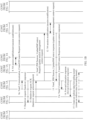
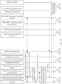
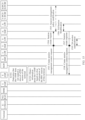
- FIG. 1A and FIG. 1B show a preparation phase of an existing 4G-to-5G handover (handover, HO) procedure.
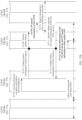
- FIG. 2A and FIG. 2B are an execution phase of an existing 4G-to-5G handover procedure.
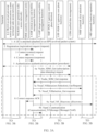
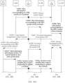
- FIG. 3A and FIG. 3B are an existing 4G-to-5G relocation procedure.
- steps in FIG. 1A to FIG. 3B refer to a conventional technology.
- An I-AMF is an initial access and mobility management function (initial access and mobility management function, initial AMF) network element, and a T-AMF is a target access and mobility management function (target access and mobility management function, target AMF) network element.
- FIG. 1A , FIG. 1B , FIG. 2A , and FIG. 2B show only an intermediate session management function (session management function, SMF) network element in a scenario in which a terminal roams between different areas (for example, the terminal roams between different provinces) within a service range of a same operator.
- An intermediate session management function network element in a scenario in which the terminal roams between different operator networks (for example, international roaming) may be referred to as a visited V-SMF
- an intermediate user plane function (user plane function, UPF) network element in a roaming scenario may be referred to as a visited V-UPF.
- an intermediate SMF may be referred to as an intermediate SMF (intermediate SMF, I-SMF), and an intermediate UPF may be referred to as an intermediate UPF (intermediate UPF, I-UPF).
- I-SMF intermediate SMF
- I-UPF intermediate UPF
- embodiments of this application provide a communication method.
- the method is applied to an interworking scenario, and is specifically applied to a scenario in which a terminal moves from a coverage area of a second network to a coverage area of a first network.
- the second network may be but is not limited to a 4G network
- the first network may be but is not limited to a 5G network.
- FIG. 4 is an example of a network architecture according to an embodiment of this application.
- the network architecture in this embodiment of this application includes an existing 5GS.
- the 5GS includes an access and mobility management function (access and mobility management function, AMF) network element, a session management function (session management function, SMF) network element, a user plane function (user plane function, UPF) network element, a unified data management (unified data management, UDM) network element, a policy control function (policy control function, PCF) network element, an authentication server function (authentication server function, AUSF) network element, a network exposure function (network exposure function, NEF) network element, and some network elements that are not shown, for example, a network function repository function (network function repository function, NRF) network element.
- AMF access and mobility management function
- SMF session management function
- UPF user plane function
- UDM unified data management
- PCF policy control function
- authentication server function authentication server function
- AUSF network exposure function
- NEF network exposure function
- a terminal accesses the 5GS via an access network device, the terminal communicates with the AMF network element through a next generation (Next generation, N) 1 interface (N1 for short), the access network device communicates with the AMF network element through an N2 interface (N2 for short), the access network device communicates with the UPF network element through an N3 interface (N3 for short), the AMF network element communicates with the SMF network element through an N11 interface (N11 for short), the AMF network element communicates with the UDM network element through an N8 interface (N8 for short), the AMF network element communicates with the AUSF network element through an N12 interface (N12 for short), the AMF network element communicates with the PCF network element through an N15 interface (N15 for short), the SMF network element communicates with the PCF network element through an N7 interface (N7 for short), the SMF network element communicates with the UPF network element through an N4 interface (N4 for short), the NEF network element
- a network architecture in an embodiment of this application may further include a mobility management entity (mobility management entity, MME) in the EPS.
- MME mobility management entity
- the MME communicates with an SMF network element through an N26 interface (N26 for short).
- the network architecture in this embodiment of this application may further include another network element in the EPS, for example, a network element or device such as an evolved universal mobile telecommunications system (universal mobile telecommunications system, UMTS) territorial radio access network (evolved UMTS territorial radio access network, E-UTRAN) device, a packet data network (packet data network, PDN) gateway user plane function (PDN gateway user plane function, PGW-U) network element, a PDN gateway control plane function (PDN gateway control plane function, PGW-C) network element, a policy and charging rules function (policy and charging rules function, PCRF) network element, or a home subscriber server (home subscriber server, HSS).
- a network element or device such as an evolved universal mobile telecommunications system (universal mobile telecommunications system, UMTS) territorial radio access network (evolved UMTS territorial radio access network, E-UTRAN) device, a packet data network (packet data network, PDN) gateway user plane function (PDN gateway
- FIG. 5(a) is a schematic diagram of an existing 5GS-EPS interworking architecture.
- the 5GS and EPS share a UPF network element+the PGW-U network element, the SMF network element+the PGW-C network element, a PCF network element+the PCRF network element, and a UDM network element+the HSS.
- "+" represents integrated configuration.
- the UPF is a user plane function network element in the 5GS
- the PGW-U is a gateway user plane function network element that is in the EPS and that corresponds to the UPF
- the SMF is a session management function network element in the 5GS
- the PGW-C is a gateway control plane function network element that is in the EPS and that corresponds to the SMF
- the PCF is a policy control function network element in the 5GS
- the PCRF is a policy and charging rules function network element that is in the EPS and that corresponds to the PCF.
- the 5GS-EPS interworking architecture may further include the MME and a serving gateway (Serving Gateway, SGW) in the EPS.
- the 5GS-EPS interworking architecture may further include a network slice selection function (network slice selection function, NSSF) network element and some network elements that are not shown, for example, an NEF network element. This is not specifically limited in this embodiment of this application.
- a terminal accesses the EPS via the E-UTRAN device, and a terminal accesses the 5GS via a next generation radio access network (next generation radio access network, NG-RAN) device.
- the E-UTRAN device communicates with the MME through an S1-MME interface.
- the E-UTRAN device communicates with the SGW through an S1-U interface.
- the MME communicates with the SGW through an S11 interface.
- the MME communicates with the UDM network element+the HSS through an S6a interface.
- the MME communicates with an AMF network element through an N26 interface.
- the SGW communicates with the UPF network element+the PGW-U network element through an S5-U interface.
- the SGW communicates with the SMF network element+the PGW-C network element through an S5-C interface.
- the UPF network element+the PGW-U network element communicate with the NG-RAN device through an N3 interface.
- the UPF network element+the PGW-U network element communicate with the SMF network element+the PGW-C network element through an N4 interface.
- the SMF network element+the PGW-C network element communicate with the PCF network element+the PCRF network element through an N7 interface.
- the UDM network element+the HSS communicate with the SMF network element+the PGW-C network element through an N10 interface.
- the UDM network element+the HSS communicate with the AMF network element through an N8 interface.
- the PCF network element+the PCRF network element communicate with the AMF network element through an N15 interface.
- the SMF network element+the PGW-C network element communicate with the AMF network element through an N11 interface.
- the AMF network element communicates with the NG-RAN device through an N2 interface.
- the AMF network element communicates with the terminal through an N1 interface.
- An operator may obtain a plurality of virtual networks, namely, network slices, through slicing on a hardware infrastructure.
- a network slice may include one or more network functions.
- One network function may belong to one network slice, or may belong to a plurality of network slices.
- a network function corresponds to a specific physical resource, and the physical resource includes but is not limited to access, connection, computing, and storage resources.
- the network function is, for example, a UPF, a UDM, or an AMF.
- a terminal may access different network slices, and then connect to a core network through a PDU session on a corresponding network slice, to obtain a service.
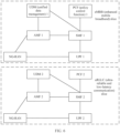
- FIG. 6 is used as an example.
- An eMBB slice is constructed on an NG-RAN, a UDM 1, an AMF 1, a PCF 1, an SMF 1, and a UPF 1.
- a uRLLC slice is constructed on the NG-RAN, a UDM 2, an AMF 2, a PCF 2, an SMF 2, and a UPF 2.
- FIG. 5(a) is merely a schematic diagram of an existing 5GS-EPS interworking architecture.
- 5GS-EPS interworking architecture such as a roaming architecture shown in FIG. 5(b) . This is not specifically limited in embodiments.
- FIG. 4 names of the network elements and the interfaces between the network elements in FIG. 4 , FIG. 5(a) , or FIG. 5(b) are merely an example. In specific implementation, there may be other names of the network elements and the interfaces between the network elements. This is not specifically limited in embodiments of this application.
- a network architecture and a service scenario that are described in embodiments of this application are intended to describe the technical solutions in embodiments of this application more clearly, and do not constitute a limitation to the technical solutions provided in embodiments of this application.
- a person of ordinary skill in the art may know that with evolution of a network architecture and emergence of a new service scenario, the technical solutions provided in embodiments of this application are also applicable to a similar technical problem.
- the terminal (terminal) in embodiments of this application may include various computing devices having a wireless communication function, a cellular phone (cellular phone), a smartphone (smartphone), a machine type communication (machine type communication, MTC) terminal, UE, a terminal device (terminal device), and the like.
- a cellular phone cellular phone
- a smartphone smart phone
- MTC machine type communication
- UE terminal device
- terminal device terminal device
- the access network device in embodiments of this application is a device that accesses the core network, for example, may be an NG-RAN device, an E-UTRAN device, a base station, or a non-3rd generation partnership project (3rd generation partnership project, 3GPP) access network device.
- the base station may be in various forms, such as a macro base station, a micro base station (also referred to as a small cell), a relay station, and an access point.
- the devices in embodiments of this application each may be implemented by one device, may be jointly implemented by a plurality of devices, or may be implemented as a functional module in one or more devices.
- This is not specifically limited in embodiments of this application. It may be understood that the foregoing functions may be network elements in a hardware device, may be software functions running on dedicated hardware, or may be virtualization functions instantiated on a platform (for example, a cloud platform).
- FIG. 7 is a schematic diagram of a structure of a communication device according to an embodiment of this application.
- the communication device 400 includes at least one processor 401, a memory 403, and at least one communication interface 404.
- the processor 401 may be a general purpose central processing unit (central processing unit, CPU), a microprocessor, an application-specific integrated circuit (application-specific integrated circuit, ASIC), or one or more integrated circuits configured to control program execution of the solutions in this application.
- CPU central processing unit
- ASIC application-specific integrated circuit
- the path may be a path between the components, and the path is for transmitting information between the foregoing components.
- the communication interface 404 is any apparatus such as a transceiver, is configured to communicate with another device or a communication network such as the Ethernet, a radio access network (radio access network, RAN), or a wireless local area network (wireless local area network, WLAN).
- a radio access network radio access network, RAN
- a wireless local area network wireless local area network, WLAN
- the memory 403 may be a read-only memory (read-only memory, ROM) or another type of static storage device that can store static information and instructions, or a random access memory (random access memory, RAM) or another type of dynamic storage device that can store information and instructions, or may be an electrically erasable programmable read-only memory (electrically erasable programmable read-only memory, EEPROM), a compact disc read-only memory (compact disc read-only memory, CD-ROM) or another compact disc storage, an optical disc storage (including a compressed optical disc, a laser disc, an optical disc, a digital versatile disc, a Blu-ray disc, or the like), a magnetic disk storage medium or another magnetic storage device, or any other medium that can be configured to carry or store expected program code in a form of instructions or a data structure and that can be accessed by a computer, but is not limited thereto.
- the memory may exist independently, and is connected to the processor through a communication line. The memory may alternatively be integrated with the processor.
- the memory 403 is configured to store computer-executable instructions for performing the solutions in this application, and the processor 401 controls execution of the computer-executable instructions.
- the processor 401 is configured to execute the computer-executable instructions stored in the memory 403, to implement communication methods provided in the following embodiments of this application.
- the computer-executable instructions in this embodiment of this application may also be referred to as application program code. This is not specifically limited in this embodiment of this application.
- the processor 401 may include one or more CPUs such as a CPU 0 and a CPU 1 in FIG. 7 .
- the communication device 400 may include a plurality of processors such as the processor 401 and a processor 408 in FIG. 7 .
- Each of the processors may be a single-core (single-CPU) processor, or may be a multi-core (multi-CPU) processor.
- the processor herein may be one or more devices, circuits, and/or processing cores configured to process data (for example, computer program instructions).
- the communication device 400 may be a general-purpose device or a special-purpose device. In specific implementation, the communication device 400 may be any device having a structure similar to that in FIG. 7 . A type of the communication device 400 is not limited in this embodiment of this application.
- names of messages between network elements, names of parameters in the messages, or the like in the following embodiments of this application are merely an example, and there may alternatively be other names in specific implementation. This is not specifically limited in embodiments of this application.
- a communication method is applied to the network architecture shown in FIG. 4 , FIG. 5(a) , or FIG. 5(b) .
- the communication method provided in an embodiment of this application includes the following steps.
- S801 Obtain slice information of a session.
- Step S801 may be performed by an I-AMF or a T-AMF.
- the I-AMF is an AMF initially selected for the terminal.
- an AMF may be re-allocated, and the I-AMF may select a T-AMF that can provide a service for the terminal.
- the I-AMF supports the slice information of the session, it indicates that the I-AMF can provide a needed slice service for the terminal, and step S801 may be performed by the I-AMF.
- step S801 may be performed by the T-AMF.
- the I-AMF performs step S801, and the I-AMF may send the slice information of the session to the T-AMF.
- an AMF re-allocation (Re-allocation) procedure further needs to be performed.
- the I-AMF sends a second message to the NRF, where the second message is for querying for identification information of the T-AMF.
- the I-AMF receives the identification information of the T-AMF from the NRF.
- the I-AMF sends a user context to the T-AMF.
- the slice information identifies a network slice.
- the slice information may be single network slice selection assistance information (single network slice selection assistance information, S-NSSAI).
- Slice information of a PDU session of the terminal may be, for example, in-used S-NSSAI allocated by an anchor session management function (anchor SMF, A-SMF) network element to the terminal or other slice information.
- anchor SMF anchor SMF
- A-SMF anchor session management function
- the A-SMF may be the SMF+the PGW-C shown in FIG. 5(a) or FIG. 5(b) .
- the A-SMF allocates, to the terminal, an IP address for accessing the data network (for example, the Internet).
- An anchor means that the A-SMF does not change in a moving process of the terminal. Once the A-SMF changes, the IP address allocated by the A-SMF to the terminal becomes invalid, and a service of the terminal is interrupted.
- an anchor user plane function (anchor UPF, A-UPF) network element may be the UPF+the PGW-U shown in FIG. 5(a) or FIG. 5(b) .
- anchor UPF anchor UPF
- A-UPF anchor user plane function
- obtaining the slice information may be implemented as: receiving the slice information from the A-SMF.
- an AMF receives a session context from the A-SMF, where the session context includes the slice information.
- the terminal may have a plurality of PDU sessions, the plurality of PDU sessions may correspond to a plurality of A-SMFs, and slice information of the terminal includes slice information from the plurality ofA-SMFs.
- obtaining the slice information may be implemented as: receiving the slice information from the MME.
- an AMF receives a user context from the MME, where the user context includes the slice information.
- S802 Send a first message to the NRF.
- step S802 may be performed by the I-AMF.
- step S802 may be performed by the T-AMF.
- the first message includes the slice information of the session, the first message requests identification information of an intermediate session management function (I-SMF or V-SMF) network element, the intermediate session management function network element is configured to manage an intermediate user plane function network element, and the intermediate user plane function network element is configured to forward service data between the access network device to which the terminal is connected and the anchor user plane function network element when the terminal moves out of a service area of the anchor user plane function network element.
- I-SMF intermediate session management function
- V-SMF V-SMF
- the identification information of the intermediate session management function network element is, for example, but not limited to, an IP address.
- the first message may be a discovery request (Nnrf_NF_Discovery), and the discovery request includes the slice information.
- the NRF may search, based on the slice information, for an intermediate network device, for example, the I-SMF, that supports a corresponding slice, and send information about the intermediate network device to the AMF, so that the AMF can learn of the information about the intermediate network device.
- the I-AMF performs step S801, and the I-AMF may obtain the slice information of the session from the A-SMF or the MME, and send the first message to the NRF, where the first message carries the slice information of the session, to query for the identification information of the I-SMF or the V-SMF that supports the slice information of the session.
- the T-AMF performs step S801, and the T-AMF may obtain the slice information of the session from the I-AMF, the A-SMF, or the MME, and send the first message to the NRF, where the first message carries the slice information of the session, to query for the identification information of the I-SMF or the V-SMF.
- S803 Receive the identification information of the intermediate SMF from the NRF.
- step S803 may be performed by the I-AMF.
- step S803 may be performed by the T-AMF.
- the I-AMF or the T-AMF receives the identification information of the intermediate SMF from the NRF.
- the slice information of the session can be obtained, and a network function repository function network element is queried for the identification information of the intermediate session management function network element based on the slice information of the session.
- the intermediate session management function network element usually can support a network slice service needed by the terminal. In this way, subsequently, the needed network slice service can be provided for the terminal by using the intermediate session management function network element, a terminal service failure probability can be reduced, and service quality can be improved.
- the intermediate session management function network element that supports a terminal service can be directly queried for based on the slice information of the session, and there is usually no need to re-allocate an intermediate session management function network element, so that signaling overheads for re-allocation of the intermediate session management function network element are avoided.
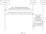
- An embodiment of this application further provides a communication method. Refer to FIG. 9 .
- the method includes the following steps.
- S901 An I-AMF sends a third message to a terminal.
- the terminal receives the third message from the I-AMF.
- the third message requests identification information of the terminal.
- An identifier of the terminal is, for example, but not limited to, a subscription concealed identifier (subscription concealed identifier, SUCI) or a subscription permanent identifier (subscription permanent identifier, SUP1).
- the third message may be an identity request (Identity Request) message.
- the I-AMF receives a registration request (Registration Request), where the registration request includes a terminal status (UE Status) information element.
- the I-AMF determines, based on the terminal status information element, that the terminal is performing a 4G-to-5G mobility registration procedure. Then, the I-AMF sends the third message to the terminal.
- S902 The terminal sends the identification information of the terminal to the I-AMF.
- the I-AMF receives the identification information of the terminal from the terminal.
- the terminal sends an identity response (Identity Response) to the I-AMF, where the identity response includes the identification information of the terminal.
- the I-AMF sends a fourth message to a UDM.
- the fourth message includes identification information of the terminal.
- the fourth message may be a subscription data obtaining message (Nudm_SDM_Get).
- S904 The UDM sends subscribed slice information of the terminal to the I-AMF.
- the I-AMF receives the subscribed slice information of the terminal from the UDM.
- the subscribed information may be, for example, subscribed S-NSSAI.
- the identification information of the terminal may be unencrypted identification information. That is, in step S902, the terminal sends the unencrypted identification information to the I-AMF.
- the I-AMF may obtain the subscribed slice information from the UDM by using the unencrypted identification information of the terminal directly.
- the identification information received by the I-AMF from the terminal is encrypted identification information.
- the I-AMF needs to interact with the UDM to perform an authentication procedure.
- the UDM sends decrypted identification information to the I-AMF.
- the method refer to an embodiment corresponding to FIG. 14 .
- the I-AMF can obtain the identification information of the terminal from the terminal, and obtain the subscribed slice information from the UDM by using the identification information.
- the I-AMF obtains the identification information of the terminal by receiving a context from an MME.
- the I-AMF can obtain the identification information of the terminal from the terminal without depending on the MME in a live network, so that dependency on the live network is reduced, and an implementation is more flexible.
- An embodiment corresponding to FIG. 10A and FIG. 10B is applied to a case in which a terminal is handed over from a 4G network to a 5G network and an AMF obtains slice information of a PDU session of the terminal from an SMF.
- An embodiment corresponding to FIG. 11A and FIG. 11B is applied to a case in which a terminal is relocated from a 4G network to a 5G network and an AMF obtains slice information of a PDU session of the terminal from an SMF.
- An embodiment corresponding to FIG. 12A and FIG. 12B is applied to a case in which a terminal is handed over from a 4G network to a 5G network and an AMF obtains slice information of a PDU session of the terminal from an MME.
- An embodiment corresponding to FIG. 13A and FIG. 13B is applied to a case in which a terminal is relocated from a 4G network to a 5G network and an AMF obtains slice information of a PDU session of the terminal from an MME.
- An embodiment corresponding to FIG. 14 is applied to a case in which a terminal is relocated from a 4G network to a 5G network and an AMF obtains slice information of a PDU session of the terminal from a UDM.
- the terminal is handed over from the 4G network to the 5G network, and the AMF obtains the slice information of the PDU session of the terminal from the SMF.
- a communication method provided in this embodiment of this application includes the following steps.
- the terminal is attached to the 4G network, and establishes a PDN connection (PDN connection).
- PDN connection PDN connection
- an A-SMF allocates the slice information such as S-NSSAI to the terminal, and sends the S-NSSAI to the terminal by using a PDN connection establishment response message.
- the slice information allocated by the A-SMF to the terminal is slice information corresponding to the PDU session after the 4G PDN connection is mapped to the 5G PDU session.
- S1002 An E-UTRAN device sends Handover Required (Handover Required) to an MME.
- Handover Required carries a target tracking area identity (target tracking area identity, target TAI) and a target NG-RAN ID.
- target TAI target tracking area identity
- target NG-RAN ID is an identifier of an NG-RAN device to which the terminal is handed over.
- the MME sends a forward relocation request (Forward Relocation Request) message to an initial AMF (Initial AMF, I-AMF).
- the AMF obtains a user context through this step.
- the MME queries a domain name server (DNS, Domain Name Server) for information about a target AMF based on the target TAI. Assuming that the DNS returns an address of the I-AMF to the MME, the MME sends the forward relocation request message to the I-AMF, where the message includes the user context.
- the user context includes information such as the target TAI, the target NG-RAN ID, and an identifier of the A-SMF corresponding to the PDU session of the terminal.
- the I-AMF sends a context request to the A-SMF.
- the I-AMF queries an NRF for an internet protocol (internet protocol, IP) address of the A-SMF based on the identifier, for example, a PGW node name, of the A-SMF obtained from the MME, and the NRF feeds back the IP address of the A-SMF to the I-AMF.
- the NRF further feeds back, to the I-AMF, information such as slice information (for example, S-NSSAI) supported by the A-SMF and a TAI that the A-SMF can serve.
- slice information for example, S-NSSAI
- the I-AMF invokes a session context request (Nsmf_PDUSession_Context Request) service of the A-SMF to send the context request to the A-SMF, where the context request requests the slice information of the session.
- a session context request Nsmf_PDUSession_Context Request
- the terminal may have one or more PDU sessions, each PDU session corresponds to one piece of slice information, and a slice corresponding to the piece of slice information is established on one A-SMF. That is, the PDU session corresponds to the A-SMF.
- the I-AMF needs to obtain slice information of the plurality of PDU sessions from A-SMFs corresponding to all sessions of the terminal.
- S1005 The A-SMF feeds back the slice information of the session to the I-AMF.
- the A-SMF allocates corresponding 5G slice information to the PDN connection in the PDN connection create process in step S1001.
- the A-SMF sends a session context response (Nsmf_PDUSession_Context Response) message to the I-AMF, where the message includes a session context, and the session context includes the slice information of the PDU session of the terminal.
- the session context includes the slice information of the PDU session that corresponds to the A-SMF and that is in the one or more PDU sessions of the terminal.
- an I-AMF After receiving the forward relocation request from the MME, an I-AMF can obtain the slice information of the session from the A-SMF, so that an intermediate SMF is subsequently queried for based on the slice information of the session, and the found intermediate SMF usually can support a slice service needed by the terminal. This is different from the conventional technology.
- the I-AMF determines whether a terminal service is supported.
- the I-AMF performs determining based on locally configured slice information and the slice information of the PDU session of the terminal. If the I-AMF does not support a slice of the terminal, the I-AMF does not support the terminal service. If the I-AMF supports a slice of the terminal, the I-AMF supports the terminal service.
- step S1007 is performed, and AMF relocation is needed, so that a relocated AMF provides a service for the terminal.
- the I-AMF supports the terminal service, the I-AMF is a T-AMF, and can provide a service for the terminal, and step S1007 does not need to be performed. That is, AMF relocation is not needed.
- the slice information S-NSSAI of the PDU session of the terminal indicates that the terminal needs an eMBB-type slice, and S-NSSAI locally configured on the I-AMF includes the eMBB-type slice. In this case, it is considered that the I-AMF supports the terminal service.
- S1007 The I-AMF, an NSSF, and the NRF exchange signaling.
- the I-AMF interacts with the NSSF and the NRF, so that the I-AMF queries for an address of the target AMF (target AMF, T-AMF). In this way, the T-AMF can be relocated subsequently, and the T-AMF provides a network slice service for the terminal.
- the I-AMF sends the slice information of the session to the T-AMF.
- the I-AMF sends an Namf_Communication_CreateUEContext request message to the T-AMF.
- This message carries the user context, so that the I-AMF transfers some information about the terminal to the T-AMF.
- the user context includes the slice information of the session.
- the user context includes the information such as the target TAI, the target NG-RAN ID, and the identifier of the A-SMF.
- S1009a The T-AMF sends a first message to the NRF.
- the first message may be, for example, a network function discovery (Nnrf_NF_Discovery) request message, and the request message carries the target TAI and the slice information of the session.
- the first message requests identification information of the intermediate SMF.
- the T-AMF determines, based on the target TAI obtained from the I-AMF, whether the I-SMF (a V-SMF in an international roaming scenario) is needed, so that the I-SMF provides a service for the terminal. Specifically, if the target TAI is a TAI that the A-SMF can serve, the I-SMF is not needed. Otherwise, the I-SMF is needed to provide a service for the terminal. In this case, the T-AMF sends the first message to the NRF, to obtain an address of the I-SMF or the V-SMF from the NRF.
- S1009b The NRF sends the identification information of the intermediate SMF to the T-AMF.
- the T-AMF sends an Nsmf_PDUSession_CreateSMContext request message to the I-SMF.
- the T-AMF sends the message to the I-SMF after obtaining the address of the I-SMF from the NRF, to request to create a session resource.
- the message carries the identifier of the A-SMF.
- the I-SMF sends an Nsmf_PDUSession_Create message to the A-SMF.
- This message requests the A-SMF to handover the PDN connection of the terminal to 5G. That is, the PDN connection in the 4G network migrates to the PDU session in the 5G network.
- the I-SMF sends a session create request (Nsmf_PDUSession_Create request) message to the A-SMF based on the identifier of the A-SMF received from the T-AMF.
- a session create request Nsmf_PDUSession_Create request
- N4 session modification N4 Session Modification
- the A-SMF exchanges signaling with an A-UPF (which may be the UPF+the PGW-U shown in FIG. 5(a) or FIG. 5(b) ) through the N4 session modification procedure. In this way, the A-SMF can obtain N9 interface address information of the A-UPF.
- A-UPF which may be the UPF+the PGW-U shown in FIG. 5(a) or FIG. 5(b)
- the message carries the slice information of the PDU session of the terminal (the slice information of the PDU session established on the A-SMF).
- the I-SMF determines an I-UPF (or a V-UPF) based on the slice information of the PDU session of the terminal.
- the I-SMF selects an I-UPF (a V-UPF in a roaming scenario) based on the slice information of the PDU session of the terminal and the target TAI obtained from the T-AMF.
- S1015 The I-SMF requests, through an N4 session establishment procedure, the I-UPF to allocate an N9 interface address.
- the I-SMF returns a create session management context response (Nsmf_PDUSession_CreateSMContext Response) to the T-AMF.
- step 9 For specific implementation of the procedure, refer to step 9 to step 15 in FIG. 1B and step 1 to step 13 in FIG. 2A and FIG. 2B .
- a communication method provided in this embodiment of this application includes the following steps.
- S1101 The terminal is attached to the 4G network, and establishes a PDN connection.
- S1102 Procedure of relocation from the 4G network to the 5G network.
- step 2 Refer to step 2 to step 14 in FIG. 3A and FIG. 3B .
- a T-AMF sends a context request to an A-SMF.
- the context request requests a session context of the terminal.
- the T-AMF invokes an Nsmf_PDUSession context request service of the A-SMF to send a context request to the A-SMF.
- the A-SMF sends the slice information of the PDU session of the terminal to the T-AMF.
- the A-SMF returns the session context of the terminal to the T-AMF.
- the session context includes the slice information of the PDU session of the terminal.
- the session context includes slice information of a PDU session that corresponds to the A-SMF and that is in one or more PDU sessions of the terminal.
- the T-AMF determines, based on a target TAI, whether an I-SMF needs to be inserted.
- S1106a The T-AMF sends a first message to an NRF.
- the T-AMF determines that the I-SMF that provides a service for the terminal needs to be inserted, the T-AMF sends the first message to the NRF, where the first message carries the slice information of the session and the target TAI, to query the NRF for an I-SMF that satisfies a condition.
- S1106b The NRF sends identification information of the I-SMF to the T-AMF.
- the NRF queries, based on the slice information and the target TAI, for an I-SMF that can serve a corresponding TA and that supports a corresponding slice, and feeds back an address of the I-SMF to the T-AMF.
- the T-AMF sends an Nsmf_PDUSession_CreateSMContext request message to the I-SMF.
- This message requests the I-SMF to create a session resource.
- the I-SMF selects an I-UPF based on the slice information, the target TAI, and local configuration information.
- the I-SMF selects an I-UPF that can serve a corresponding TA and that supports a corresponding slice.
- the I-SMF requests the I-UPF to allocate a user plane resource.
- the I-SMF sends an Nsmf_PDUSession_Create request message to the A-SMF.
- the I-SMF notifies, by using this message, the A-SMF to enable the 4G PDN connection of the terminal to migrate to a 5G PDU session.
- the A-SMF exchanges signaling with an A-UPF, and the A-SMF may notify the A-UPF that the terminal has been relocated to the 5G network.
- S1112 The A-SMF replies to the I-SMF with an Nsmf_PDUSession_Create response message.
- This message indicates that the session is successfully handed over to 5G.
- This message indicates that the session is successfully handed over to 5G.
- step 18 Same as step 18 to step 22 in FIG. 3B . Details are not described again.
- the PDN connection established by the terminal in 4G can migrate to the 5G PDU session, so that the terminal establishes a connection to a 5G core network device by using the PDU session.
- the AMF can obtain the slice information of the PDU session of the terminal from the A-SMF, thereby selecting intermediate network devices, for example, the I-SMF and the I-UPF, that support a slice needed by the PDU session. This avoids SMF and UPF re-allocation, thereby simplifying an interworking signaling procedure.
- the terminal is handed over from the 4G network to the 5G network, and the AMF obtains the slice information of the PDU session of the terminal from the MME.
- a communication method provided in this embodiment of this application includes the following steps.
- the terminal sends a PDN connection establishment request (PDN Connection Establishment request) to the MME.
- PDN Connection Establishment request PDN Connection Establishment request
- the terminal is attached to the 4G network, and initiates the PDN connection establishment request to the MME, and the terminal may perform a corresponding service by using the established PDN connection.
- S1202 The MME sends a create session request (Create Session Request) message to an A-SMF.
- This message requests establishment of the PDN connection.
- S1203 The A-SMF feeds back a create session response (Create Session Response) to the MME.
- the A-SMF allocates a network slice to the PDN connection of the terminal, and feeds back a create session response message to the MME, where the message indicates that the PDN connection is successfully established.
- the create session response carries information about the allocated slice.
- S1204 The MME parses the create session response to obtain the slice information.
- the create session response includes a protocol configuration options (protocol configuration options, PCO) information element, and the PCO information element includes the slice information.
- PCO protocol configuration options
- the MME parses the PCO in the create session response to obtain the slice information.
- the MME stores the slice information.
- the MME does not parse the PCO in the create session response, and therefore cannot obtain the slice information.
- the MME performs parsing, and obtain the slice information associated with the terminal, to query, based on the slice information, for an AMF that provides a service for the terminal, and/or send the slice information to the AMF, to reduce a latency caused by network element relocation and reduce signaling overheads.
- the MME sends a PDN connection establishment response (PDN Connection Establishment Response) to the terminal.
- PDN Connection Establishment Response PDN Connection Establishment Response
- the PDN connection establishment response indicates that the PDN connection is successfully established.
- the PDN connection establishment response carries the slice information.
- S1206 An E-UTRAN device sends Handover Required (Handover Required) to the MME.
- the terminal moves from a coverage area in the 4G network to a coverage area in the 5G network, the terminal may be in connected (CONNECTED) mode and have a service with a network, and the E-UTRAN device triggers a 4G-to-5G handover procedure of the terminal based on a measurement report of the terminal and the like.
- the Handover Required message carries a target TAI, namely, a 5G TAI to which handover needs to be performed.
- S1207 The MME queries a DNS for an IP address of the AMF based on the target TAI.
- a correspondence between a TAI, a slice, and an AMF may be configured on the DNS.
- the corresponding AMF may be queried for based on the TAI and slice information.
- step S1207 may alternatively be implemented as follows:
- the MME queries the DNS for an IP address of a target AMF based on the target TAI and the slice information.
- the MME sends the target TAI and the slice information of the PDU session of the terminal to the DNS.
- the DNS can select, based on the target TAI and the slice information, an AMF that can serve a corresponding TA and that supports a needed slice service, and feed back an address of the AMF to the MME.
- it can be ensured that the selected AMF supports the slice information of the PDU session of the terminal, to reduce a probability that AMF relocation is needed, reduce signaling overheads, and reduce a latency of an interworking procedure.
- S1208 The MME sends the slice information of the PDU session of the terminal to the I-AMF.
- the slice information is used by the I-AMF to select an intermediate SMF.
- the MME sends a forward relocation request message to the I-AMF, where the message carries a user context of the terminal, and the user context includes the slice information of the PDU session of the terminal.
- the I-AMF determines, based on the slice information of the PDU session of the terminal and locally configured slice information, whether a terminal service is supported.
- S1210b The I-AMF sends the slice information of the session to the T-AMF.
- the I-AMF sends the user context to the T-AMF, and the user context includes the slice information of the session.
- S1211 The T-AMF sends a first message to the NRF.
- S1212 The NRF sends identification information of the I-SMF to the T-AMF.
- steps S1211 and S1212 refer to the foregoing steps S1009a and S1009b.
- the terminal is relocated from the 4G network to the 5G network, and the AMF obtains the slice information of the PDU session of the terminal from the MME.
- a communication method provided in this embodiment of this application includes the following steps.
- S1306 The terminal is relocated from the 4G network to the 5G network.
- step 2 to step 9b in FIG. 3A Refer to step 2 to step 9b in FIG. 3A .
- a T-AMF sends a context request message to the MME.
- This message requests to obtain a user context.
- S1308 The MME sends the slice information of the PDU session of the terminal to the T-AMF.
- the MME returns a context response message to the T-AMF, where the message carries the user context, and the user context includes the slice information of the PDU session of the terminal.
- This message indicates that the user context is received.
- the T-AMF sends a first message to an NRF.
- the NRF sends identification information of an I-SMF to the T-AMF.
- the MME obtains the slice information of the PDU session from the response message sent by the A-SMF to the terminal, and transfers the slice information to the AMF. In this way, it can be ensured that the AMF queries for the I-SMF by using correct slice information, thereby avoiding SMF re-allocation. Similarly, UPF re-allocation and the like can be avoided, and an interworking signaling procedure is simplified.
- a communication method provided in this embodiment of this application includes the following steps.
- S1401 The terminal is attached to an EPS, and creates a PDN connection.
- S1402 The terminal sends a registration request (Registration Request) to an I-AMF.
- the terminal initiates a procedure of relocation from the 4G network to the 5G network, and sends a registration request to an NG-RAN device.
- the NG-RAN device selects an AMF based on a capacity (capacity) of an AMF to which the NG-RAN device is connected, and sends the registration request to the selected AMF.
- the AMF selected by the NG-RAN is assumed to be referred to as the I-AMF.
- the registration request carries S-NSSAI requested (Requested) by the terminal.
- the registration request includes a UE status information element (information element).
- the I-AMF detects, based on the UE status information element in the registration request, that the terminal performs a 4G-to-5G mobility registration procedure.
- the UE status information element includes a first flag bit, and the first flag bit identifies whether the terminal registered with the 4G network and a registration status (a registered state or an unregistered state) in the 4G network. If the terminal registered with the 4G network, and initiates a registration request to the 5G network, the I-AMF determines that step S1402 is the 4G-to-5G mobility registration procedure.
- the I-AMF sends an identity request (Identity Request) to the terminal.
- the identity request requests an identifier of the terminal.
- the identifier of the terminal may be, but is not limited to, an SUCI.
- S1404 The terminal feeds back an identity response (Identity Response) to the I-AMF.
- the identity response carries the identifier of the terminal.
- the I-AMF obtains an SUPI of the terminal from the UDM.
- the UDM has an AUSF function.
- a relationship between the SUPI and the SUCI is that the SUCI is formed by encrypting the SUPI.
- the I-AMF initiates an authentication procedure, and the I-AMF sends a fifth message to the UDM, where the fifth message includes encrypted identification information, for example, the SUCI of the terminal.
- the UDM decrypts the SUCI into the SUPI, and feeds back the SUPI of the terminal to the I-AMF.
- the I-AMF obtains subscribed slice information of the terminal from the UDM based on the SUPI of the terminal.
- the I-AMF sends an Nudm_SDM_Get request message to the UDM, where the message carries the SUPI of the terminal.
- the UDM returns an Nudm_SDM_Get response message, where the message includes the subscribed slice information of the terminal.
- the I-AMF determines, based on the subscribed slice information and requested slice information, whether a terminal service is supported.
- the I-AMF obtains an intersection set of a requested slice and a subscribed slice, and determines, based on a locally configured slice, whether the I-AMF supports all slices in the intersection set. If the I-AMF supports all the slices in the intersection set, the terminal service is supported. Otherwise, the terminal service is not supported.
- the I-AMF obtains information about a T-AMF from an NSSF.
- the I-AMF sends an Nnssf_NSSelection_Request message to the NSSF, where the message carries requested S-NSSAI and subscribed S-NSSAI.
- the NSSF queries for the information about the T-AMF and feeds back the information about the T-AMF, for example, a name of T-AMF device, to the I-AMF based on the requested S-NSSAI and the subscribed S-NSSAI.
- the I-AMF queries an NRF for an address of the T-AMF based on the information about the T-AMF.
- the I-AMF obtains the address of the T-AMF from the NRF through an Nnrf_NF_Discovery procedure.
- the message includes some information, for example, the requested S-NSSAI, in Registration 1_mRequest.
- the message includes a user context.
- the user context includes a security context.
- the T-AMF may trust some information from the I-AMF.
- the I-AMF has performed authentication. Therefore, the security context obtained from the I-AMF is usually trustworthy.
- the T-AMF may obtain the context from an MME.
- the I-AMF does not obtain the slice information of the PDU session of the terminal from the MME. This is different from that in FIG. 13A and FIG. 13B .
- the I-AMF obtains the SUCI of the terminal in the user context by obtaining the user context from the MME. That is, the MME obtains the SUCI through steps 3 and 4 shown in FIG. 3A . In the embodiment corresponding to FIG. 14 , the I-AMF obtains the SUCI of the terminal from the terminal. In other words, the I-AMF may not obtain the user context from the MME. In this way, a conventional-technology problem that signaling overheads are high because both the I-AMF and the T-AMF obtain the user context from the MME can be avoided.
- an AMF is a re-allocated T-AMF (where in a scenario in which AMF re-allocation is not needed, the AMF may alternatively be an I-AMF), and an intermediate session management function network element is an I-SMF (where in some other embodiments, the intermediate session management function network element may alternatively be a V-SMF).
- the method includes the following steps.
- the T-AMF determines that the I-SMF does not support a slice of a PDU session of a terminal.
- the T-AMF receives slice information (S-NSSAI) of the PDU session of the terminal from an I-AMF in step 8a shown in FIG. 1B .
- the T-AMF determines, based on the slice information of the PDU session of the terminal, whether the I-SMF can serve the terminal.
- the slice of the PDU session of the terminal is an eMBB-type slice, and needs a high bandwidth, and the I-SMF does not support a high-bandwidth slice.
- the T-AMF determines that the I-SMF does not support a terminal service.
- SMF relocation or referred to as reselection
- reselection is needed, to relocate the terminal to an SMF that can support the terminal service.
- the T-AMF obtains information about a T-SMF based on the slice information of the PDU session of the terminal.
- the T-AMF queries an NRF for the information about the T-SMF to which the terminal needs to be relocated. Specifically, the T-AMF sends Nnrf_NF_Discovery to the NRF, where the message carries a target TAI and the slice information of the PDU session of the terminal, to obtain an address of the T-SMF from the NRF.
- the T-AMF sends a create session management context request (Nsmf_PDUSession_CreateSMContext Request) to the T-SMF.
- the create session management context request requests to create a session resource.
- the T-SMF sends a session create request (Nsmf_PDUSession_Create request) to an A-SMF.
- This message requests the A-SMF to enable a PDN connection established by the terminal in a 4G network to migrate to a PDU session in a 5G network.
- S1505 Session management policy (SM policy) modification procedure.
- SM policy Session management policy
- the A-SMF exchanges signaling with a PCF, so that the SMF updates a session management policy, and notifies the PCF that the terminal is to be handed over to the 5G network.
- the A-SMF exchanges signaling with an anchor UPF to obtain N9 interface address information of the anchor UPF.
- S1507 The A-SMF replies to the T-SMF with a session create response.
- the session create response indicates that the PDN connection of the terminal has migrated to a 5G side.
- the session create response carries the slice information, for example, in-used S-NSSAI, corresponding to the PDU session of the terminal.
- T-SMF returns a create session management context response to the T-AMF.
- the create session management context response indicates that the session has been handed over to the 5G side.
- the create session management context response carries the slice information, for example, the in-used S-NSSAI, of the PDU session of the terminal.
- the T-SMF selects an intermediate UPF, namely, a T-UPF (a V-UPF in a roaming scenario) from a local configuration based on the slice information that is of the PDU session and that is obtained in step S1507 and the target TAI, and obtains an N9 interface address of the T-UPF by using the N4 session establishment procedure.
- an intermediate UPF namely, a T-UPF (a V-UPF in a roaming scenario) from a local configuration based on the slice information that is of the PDU session and that is obtained in step S1507 and the target TAI, and obtains an N9 interface address of the T-UPF by using the N4 session establishment procedure.
- the AMF may perform SMF reselection, to relocate the terminal to the SMF that supports the slice of the PDU session of the terminal, to ensure service continuity in an interworking procedure.
- An embodiment of this application further provides a communication method.
- the method includes the following steps.
- the A-UPF communicates with an I-UPF based on the default slice information.
- the I-UPF When a terminal moves out of a service area of the A-UPF, the I-UPF is configured to forward service data between the A-UPF and an access network device to which the terminal is connected.
- slice information of which the A-UPF usually learns is slice information of a real session, and the I-UPF learns of the default slice information.
- the A-UPF and the I-UPF communicate with each other by using different slices.
- the A-UPF communicates with the I-UPF by using a real slice, and the I-UPF communicates with the A-UPF on a default slice.
- a tunnel between the A-UPF and the I-UPF may be unavailable.
- the A-UPF can learn of the default slice information.
- the A-UPF can communicate with the I-UPF by using the default slice, and the 1-UPF can also communicate with the A-UPF by using the default slice.
- the tunnel between the A-UPF and the I-UPF can be available, and a probability of a communication failure caused by tunnel unavailability is reduced.
- the method further includes the following steps.
- S16a3 In a registration procedure, the A-UPF obtains slice information of a session.
- the A-UPF communicates with the I-UPF based on the slice information of the session.
- the I-UPF has learned of the slice information of the session. Therefore, in this embodiment of this application, it is considered that the slice information of the A-UPF is updated to the slice information of the session in the registration procedure through step S16a3. In this way, both the A-UPF and the I-UPF learn of the slice information of the session, and the A-UPF can communicate with the I-UPF by using the real session slice, and the tunnel between the A-UPF and the I-UPF can be available.
- the A-UPF may delete the default slice information, to release a related resource. Specifically, in the registration procedure, the A-UPF receives first indication information, where the first indication information indicates to delete the default slice information; and the A-UPF deletes the default slice information based on the first indication information.
- the A-UPF may update the slice information of the A-UPF.
- the slice information of the A-UPF is updated to the default slice information, to be consistent with the slice information of the I-UPF in the interworking procedure.
- the slice information of the A-UPF is updated to the slice information of the real session, to be consistent with the slice information of the I-UPF in the registration procedure.
- the A-UPF and the I-UPF can communicate with each other by using the default slice; and in the registration procedure, the A-UPF and the I-UPF can communicate with each other by using the real session slice, and it is ensured that the tunnel between the A-UPF and the I-UPF can be available.
- the communication method includes a handover preparation phase shown in FIG. 16(b) , a handover execution phase shown in FIG. 17A and FIG. 17B , and a registration procedure shown in FIG. 18A and FIG. 18B .
- the method includes the following steps.
- the preparation phase includes steps 1 to 3 shown in FIG. 1A , the following steps S1601 to S1612, and steps 13 to 15 shown in FIG. 1B .
- An I-AMF sends a create session management context request to an I-SMF.
- step 4 refers to step 4 shown in FIG. 1A .
- the create session management context request includes information about a default slice, for example, default NSSAI (default NSSAI).
- the default slice may be locally configured on the I-AMF and for 4G-5G interworking.
- the default slice may be inconsistent with a slice corresponding to a PDU session of a terminal.
- the I-SMF sends a session create request to an anchor SMF.
- the session create request includes one or more of the following information: an SUPI, a data network name (data network name, DNN), a PDU session identifier (PDU Session ID), an ID of the I-SMF, a PDU session type (PDU Session Type), user location information (User location information), and an EPS interworking support indication (EPS interworking support indication).
- SUPI Secure Digital
- DNN data network name
- PDU Session ID PDU session identifier
- ID an ID of the I-SMF
- PDU Session Type PDU session type
- user location information User location information
- EPS interworking support indication EPS interworking support indication
- S1603 Session management policy modification procedure.
- step 5 shown in FIG. 1A Refer to step 5 shown in FIG. 1A .
- S1604 The A-SMF sends the information about the default slice to an anchor UPF.
- information about the default slice for 4G-5G interworking is configured on the A-SMF.
- the information about the default slice is the same as that of the default slice configured on the I-AMF.
- the A-SMF initiates an N4 session modification procedure to the anchor UPF.
- the A-SMF sends the information about the default slice to the anchor UPF.
- an SMF is configured to allocate N9 tunnel information. Specifically, the SMF allocates the N9 tunnel information based on the default slice, and sends the allocated N9 tunnel information to a UPF.
- the SMF delivers a packet detection rule (packet detection rule, PDR) to the anchor UPF.
- PDR is for traffic classification.
- the N9 tunnel information includes a fully qualified tunnel endpoint identifier (Fully Qualified TEID, F-TEID).
- F-TEID includes a tunnel TEID and a tunnel IP. Subsequently, information may be transmitted between an I-UPF and the anchor UPF through an N9 tunnel.
- the anchor UPF is configured to allocate N9 tunnel information. Specifically, the anchor UPF allocates the N9 tunnel information based on the received information about the default slice, and sends the N9 tunnel information to the A-SMF.
- S1605 The A-SMF sends N9 tunnel information of a UPF to the I-SMF.
- the A-SMF sends a session create response to the I-SMF, where the session create response carries N9 tunnel information (allocated by the anchor UPF or the A-SMF) on an anchor UPF side.
- the N9 tunnel is a core network tunnel (CN Tunnel).
- the I-SMF sends the N9 tunnel information on the anchor UPF side to the I-UPF, so that the I-UPF sends user plane data of the terminal to the anchor UPF.
- the session create response includes S-NSSAI corresponding to the PDU session of the terminal.
- the I-SMF returns a create session management context response to the I-AMF.
- the create session management context response includes the S-NSSAI corresponding to the PDU session of the terminal.
- the I-SMF sends the information about the default slice to the I-UPF.
- step S1601 the I-SMF obtains the information about the default slice from the I-AMF, and then the I-SMF initiates an N4 session establishment procedure to the I-UPF. In the N4 session establishment procedure, the I-SMF sends the information about the default slice to the I-UPF.
- the I-SMF is configured to allocate N9 tunnel information of the I-UPF. Specifically, the I-SMF allocates the N9 tunnel information based on the information about the default slice, and sends the N9 tunnel information that is based on the information about the default slice to the I-UPF.
- the I-SMF sends the PDR of the PDU session of the terminal, CN tunnel information (for example, the N9 tunnel information of the anchor UPF), and a forwarding action rule (forwarding action rule, FAR) to the I-UPF.
- the FAR indicates whether information is forwarded, discarded, or buffered.
- S1608 The I-AMF sends a user context create request to a T-AMF.
- the I-AMF determines whether the I-AMF can support the PDU session of the terminal. If the I-AMF does not support the PDU session of the terminal, the I-AMF performs AMF re-allocation, to relocate the terminal to a T-AMF that can serve the terminal (that is, support the slice corresponding to the PDU session of the terminal).
- the user context create request includes the information about the default slice.
- This step is optional.
- the T-AMF sends the information about the default slice to an NG-RAN device.
- the T-AMF sends a handover request (Handover Request) to the NG-RAN device, where the handover request includes the information about the default slice.
- Handover Request a handover request
- N3 tunnel Info N3 tunnel information
- the NG-RAN device after receiving the information about the default slice, allocates the N3 tunnel information based on the information about the default slice, and feeds back a handover request acknowledgment (Handover Request ACK) to the T-AMF, where the handover request acknowledgment includes the N3 tunnel information.
- the N3 tunnel information includes one or more of the following information: a tunnel IP address and a TEID.
- An N3 tunnel is a core network tunnel.
- the N3 tunnel information of the NG-RAN device is sent to the I-UPF, so that when the user plane data of the terminal arrives, the I-UPF knows a forwarding path of the user plane data. That is, the user plane data is sent to the NG-RAN device.
- the T-AMF sends an update session management context request (Nsmf_ PDUSession _UpdateSMContext Request) to the A-SMF.
- Nsmf_ PDUSession _UpdateSMContext Request an update session management context request
- the update session management context request includes the N3 tunnel information (allocated by the NG-RAN device) of the NG-RAN device.
- the update session management context request indicates to update the N3 tunnel information, so that the N3 tunnel between the NG-RAN device and the I-UPF is established subsequently.
- the A-SMF indicates the A-UPF to establish an indirect forwarding tunnel that is based on the information about the default slice.
- the A-SMF initiates the N4 session modification procedure to the anchor UPF.
- the A-SMF notifies the anchor UPF of the N3 tunnel information of the NG-RAN device, and notifies the anchor UPF to establish the indirect forwarding tunnel.
- the anchor UPF establishes an indirect forwarding tunnel between the I-UPF and the NG-RAN device based on the N3 tunnel information (based on the information about the default slice), and establishes an indirect forwarding tunnel between the anchor UPF and the I-UPF based on the N9 tunnel information (based on the information about the default slice) of the I-UPF.
- a data packet buffered in the E-UTRAN device may be sent to the NG-RAN device through the indirect forwarding tunnel, that is, by using the anchor UPF and the I-UPF.
- the I-AMF selects the I-SMF based on the information about the default slice for interworking, and sends the information about the default slice to the I-SMF.
- the I-SMF sends the information about the default slice to the selected I-UPF.
- the A-SMF allocates, to the terminal, real slice information, that is, slice information corresponding to the PDU session of the terminal.
- the A-SMF sends the real slice information to the anchor UPF. It can be learned that slice information of different network elements may be inconsistent.
- the I-UPF has the information about the default slice, and the anchor UPF has the real slice information. In this case, due to isolation between different slices, the I-UPF and the anchor UPF cannot be connected to each other, and communication between the I-UPF and the anchor UPF fails.
- all end-to-end network elements learn of the information about the default slice.
- the information about the default slice is configured on the I-AMF and the A-SMF.
- the I-AMF sends the information about the default slice to the I-SMF in step S1601, and sends the information about the default slice to the T-AMF in step S1608, and the T-AMF sends the information about the default slice to the NG-RAN device in step S1609.
- the I-SMF sends the information about the default slice to the I-UPF in step S1607.
- the A-SMF sends the information about the default slice to the anchor UPF in step S1604.
- the network elements may communicate with each other by using the default slice. This avoids a communication failure caused by inconsistent slices of the network elements.
- the execution phase includes the following steps S1701 to S1715.
- a terminal indicates, over an air interface, to an NG-RAN device that the terminal has been handed over to a target cell.
- the NG-RAN device sends a handover notification (Handover Notification) to a T-AMF.
- a handover notification Handover Notification
- the handover notification indicates, to the T-AMF, that the terminal has been handed over to the NG-RAN device.
- the handover notification carries N3 tunnel information of the NG-RAN.
- the N3 tunnel information is generated based on default slice information.
- the T-AMF sends a forward relocation complete notification (Forward Relocation Complete Notification) to an MME.
- the forward relocation completion notification indicates that the terminal has been handed over to a 5GS.
- the T-AMF sends an update session management context request (Nsmf_ PDUSession _UpdateSMContext Request) to an I-SMF.
- Nsmf_ PDUSession _UpdateSMContext Request an update session management context request
- the I-SMF sends a session update request (Nsmf_PDUSession_Update Request) to an A-SMF.
- steps S1706 to S1708 refer to a conventional technology.
- S1709 The A-SMF sends N9 tunnel information of an I-UPF to an anchor UPF.
- an N4 session modification (N4 session modification) procedure is initiated, and the N9 tunnel information of the I-UPF is sent to the anchor UPF, to establish a downlink forwarding path of an N9 tunnel.
- the N9 tunnel information is generated based on a default slice.
- S1710 Session management policy modification procedure.
- the A-SMF triggers the session management policy modification procedure to a PCF.
- the A-SMF notifies the PCF of changes of a radio access technology (radio access technology, RAT) type and a location (Location) of the terminal.
- radio access technology radio access technology, RAT
- This step is optional.
- S1711 The A-SMF feeds back a session update response to the I-SMF.
- the session update response includes the N3 tunnel information of the NG-RAN device.
- the update session management context response indicates that the handover is completed.
- the update session management context response includes a PDU session ID.
- the I-SMF sends the N3 tunnel information of the NG-RAN device and N9 tunnel information of the anchor UPF to the I-UPF.
- the I-SMF sends, to the I-UPF, the N3 tunnel information allocated by the NG-RAN device, to establish a downlink forwarding path of an N3 tunnel.
- the I-SMF sends the N9 tunnel information of the anchor UPF to the I-UPF, to establish an uplink forwarding path of the N9 tunnel, namely, a forwarding path to the anchor UPF.
- both the N3 tunnel information of the NG-RAN device and the N9 tunnel information of the anchor UPF are generated based on the default slice information.
- the registration procedure after the handover procedure includes the following steps.
- An AMF sends, to an I-SMF, slice information corresponding to a PDU session of a terminal.
- the AMF refers to the foregoing T-AMF. In a scenario in which AMF re-allocation is not performed, the AMF refers to the foregoing I-AMF.
- the AMF sends a create session management context request to the I-SMF, where the create session management context request includes the slice information of the PDU session of the terminal.
- the create session management context request indicates the I-SMF to update a session.
- S1802 The I-SMF sends a session create request to an A-SMF.
- the I-SMF sends, to an I-UPF, the slice information corresponding to the PDU session of the terminal.
- the I-SMF initiates an N4 session establishment procedure to the I-UPF.
- the 1-SMF sends, to the I-UPF, the slice information corresponding to the PDU session of the terminal.
- the I-SMF generates N9 tunnel information of the I-UPF based on the slice information corresponding to the PDU session of the terminal, and sends the N9 tunnel information to the 1-UPF.
- the I-UPF generates N9 tunnel information based on the received slice information corresponding to the PDU session of the terminal.
- the I-UPF has generated the N9 tunnel information that is based on a real slice of the session, because a tunnel based on the real slice has not been established yet, the I-UPF continues to use a tunnel established based on default slice information, to send and receive data.
- the A-SMF sends, to an anchor UPF, the slice information corresponding to the PDU session of the terminal.
- the A-SMF initiates an N4 session modification procedure to the anchor UPF.
- the A-SMF sends, to the anchor UPF, the slice information corresponding to the PDU session of the terminal.
- the A-SMF generates N9 tunnel information of the anchor UPF based on the slice information corresponding to the PDU session of the terminal, and sends the N9 tunnel information to the anchor UPF.
- the anchor UPF generates N9 tunnel information based on the received slice information corresponding to the PDU session of the terminal.
- the anchor UPF establishes a core network tunnel based on the slice information corresponding to the PDU session of the terminal, for example, creates an N9 tunnel between the anchor UPF and the I-UPF.
- the anchor UPF has two types of tunnels: One is a tunnel that is based on the default slice information, and the other is a tunnel that is based on real session slice information.
- the anchor UPF first uses the tunnel that is based on the default slice information, to perform communication.
- the A-SMF sends the N9 tunnel information of the anchor UPF to the I-SMF.
- the A-SMF sends a session create response to the I-SMF, where the session create response includes the N9 tunnel information of the anchor UPF.
- the N9 tunnel information is generated based on the slice information corresponding to the PDU session of the terminal.
- the I-SMF sends a create session management context response to the AMF.
- S1 807 Session management policy modification.
- This step is optional.
- the I-SMF sends the N9 tunnel information of the anchor UPF to the I-UPF.
- the AMF sends, to an NG-RAN device, the slice information corresponding to the PDU session of the terminal.
- the AMF sends an N2 SM message to the NG-RAN device, where the N2 SM message includes the slice information of the PDU session.
- the N2 SM message further includes N3 tunnel information of the I-UPF.
- the NG-RAN device sends third indication information to the AMF.
- the third indication information indicates that N3 tunnel handover has been performed.
- the NG-RAN device creates an N3 tunnel based on the received slice information of the PDU session of the terminal. In this way, the NG-RAN device hands over uplink data of the terminal from an old N3 tunnel that is based on the default slice information to a new N3 tunnel that is based on the real slice information, and feeds back the third indication information to the AMF, to notify the AMF that the uplink data of the terminal has been handed over to the new N3 tunnel.
- S1811 The AMF sends a session create modification request (session create modification request) to the I-SMF.
- the session create modification request requests to update a session indicates that the NG-RAN device has performed N3 tunnel handover, and/or indicates to update tunnel information.
- S1812 The I-SMF sends a session create modification request to the A-SMF.
- the session create modification request requests to update the session, and/or indicates that the NG-RAN device has performed N3 tunnel handover.
- the I-SMF sends second indication information to the I-UPF.
- the second indication information indicates the I-UPF to delete the default slice information, and/or indicates the I-UPF to perform N3 tunnel handover and N9 tunnel handover.
- the I-LTPF hands over downlink data of the terminal from the N3 tunnel created based on the default slice information to the N3 tunnel created based on the real slice information, and sends the downlink data to the NG-RAN device; and hands over the uplink data of the terminal from an N9 tunnel created based on the default slice information to an N9 tunnel created based on the real slice information, and sends the uplink data to the anchor UPF.
- the I-SMF learns that the NG-RAN device has performed N3 tunnel handover. In this way, the I-SMF initiates the N4 session modification procedure to the I-UPF. In the procedure, the I-SMF sends the second indication information to the I-UPF, to indicate the I-UPF to perform N3 tunnel handover and N9 tunnel handover.
- S1814 The A-SMF sends first indication information to the anchor UPF.
- the first indication information indicates the anchor UPF to delete the default slice information, and/or indicates the anchor UPF to perform N9 tunnel handover. Specifically, the anchor UPF hands over the downlink data of the terminal from the N9 tunnel created based on the default slice information to the N9 tunnel created based on the real slice information, and sends the downlink data to the I-UPF.
- the A-SMF initiates the N4 session modification procedure to the anchor UPF.
- the A-SMF sends the first indication information to the anchor UPF.
- the anchor UPF sends the downlink data by using the tunnel that is based on the real slice information.
- S1815 The A-SMF sends fourth indication information to the I-SMF.
- the fourth indication information indicates the I-SMF to delete the default slice information.
- the A-SMF sends a session create modification response to the I-SMF, where the session create modification response carries the fourth indication information.
- S1816 The I-SMF sends the session create modification response to the AMF.
- the AMF sends fifth indication information to the NG-RAN device.
- the fifth indication information indicates the NG-RAN device to delete the default slice information.
- all end-to-end network elements can update slice information to the real slice information, namely, the slice information corresponding to the PDU session of the terminal.
- network elements may communicate with each other by using the real slice. Because the network elements communicate with each other based on a same slice, it can be ensured that a tunnel is available. For example, if slices of the I-UPF and the anchor UPF are the same (for example, both are of an eMBB type), the I-UPF and the anchor UPF can be connected to each other.
- the communication method provided in this embodiment of this application in a scenario in which the I-SMF selected by the AMF by default does not support the slice of the PDU session of the terminal and a data plane is unavailable, intermediate SMF reselection may not be performed.
- the A-SMF supports both the tunnel of the default slice and the tunnel of the real slice.
- end-to-end network elements first use the tunnel of the default slice to perform communication, then update the default slice to the real slice in the registration procedure after interworking is completed, and use the tunnel of the real slice to perform communication. In this way, in both the handover procedure and the registration procedure, the data plane can be available, so that a probability of a communication failure caused by data plane unavailability is reduced.
- sequence numbers of the foregoing processes do not mean an execution sequence.
- An execution sequence of the processes should be determined based on functions and internal logic of the processes, and should not constitute any limitation on an implementation process of embodiments of this application.
- the I-AMF, the T-AMF, the MME, the A-UPF, or another network device includes a corresponding hardware structure and/or software module for performing each function.
- the PCF network element includes a corresponding hardware structure and/or software module for performing each function.
- division into functional modules may be performed on a device such as the I-AMF, the T-AMF, the MME, the A-UPF, or the another network device (for example, the PCF network element).
- each functional module may be obtained through division corresponding to each function, or two or more functions may be integrated in one processing module.
- the integrated module may be implemented in a form of hardware, or may be implemented in a form of a software functional module. It can be noted that, in embodiments of this application, division into the modules is an example, and is merely logical function division. Another division manner may be used during actual implementation.
- FIG. 19 is a block diagram of a structure of a communication apparatus according to an embodiment of this application.
- the communication apparatus may be an I-AMF or an apparatus (for example, but not limited to, a chip system) supporting an I-AMF function, a T-AMF or an apparatus supporting a T-AMF function, an MME or an apparatus supporting an MME function, or an A-UPF or an apparatus supporting an A-UPF function.
- the communication apparatus may include a transceiver unit 1610 and a processing unit 1620.
- the transceiver unit 1610 is configured to support the communication apparatus in performing the foregoing steps S801, S802, S803, S901, and S1003, and/or is configured to perform another process of the technology in this specification.
- the processing unit 1620 is configured to assist the communication apparatus in determining whether the communication apparatus supports a slice service needed by a terminal, and/or is configured to perform another process of the technology in this specification.
- the transceiver unit 1610 is configured to support the communication apparatus in performing the foregoing steps S801, S802, S803, S1008, and S1104, and/or is configured to perform another process of the technology in this specification.
- the processing unit 1620 is configured to assist the communication apparatus in performing step S1105, and/or is configured to perform another process of the technology in this specification.
- the transceiver unit 1610 is configured to support the communication apparatus in performing the foregoing steps S1208 and S1308, and/or is configured to perform another process of the technology in this specification.
- the processing unit 1620 is configured to assist the communication apparatus in performing step S1204, and/or is configured to perform another process of the technology in this specification.
- the transceiver unit 1610 When the communication apparatus is the A-UPF or the apparatus supporting the A-UPF function, the transceiver unit 1610 is configured to support the communication apparatus in performing the foregoing steps S16a1, S16a3, and S1604, and/or is configured to perform another process of the technology in this specification.
- the processing unit 1620 is configured to control the transceiver unit 1610 to implement a transceiver function, and/or is configured to perform another process of the technology in this specification.
- the communication apparatus further includes a storage unit (not shown in FIG. 19 ).
- the storage unit is configured to store program code and data of the communication apparatus.
- the data may include but is not limited to original data, intermediate data, or the like.
- the processing unit 1620 may be a controller or the processor 401 or the processor 408 shown in FIG. 7 , for example, may be a central processing unit (Central Processing Unit, CPU), a general-purpose processor, a digital signal processor (Digital Signal Processor, DSP), an application specific integrated circuit (Application Specific Integrated Circuit, ASIC), a field-programmable gate array (Field-Programmable Gate Array, FPGA) or another programmable logic device, a transistor logic device, a hardware component, or any combination thereof.
- the processing unit 1620 may implement or execute various example logical blocks, modules, and circuits described with reference to content disclosed in this application.
- the processor may be a combination of processors implementing a computing function, for example, a combination of one or more microprocessors or a combination of a DSP and a microprocessor.
- the transceiver unit 1610 may be the communication interface 404 shown in FIG. 7 , or may be a transceiver circuit or the like.
- the storage unit may be the memory 403 shown in FIG. 7 .
- the computer program product includes one or more computer instructions.
- the computer may be a general-purpose computer, a dedicated computer, a computer network, or another programmable apparatus.
- the computer instructions may be stored in a computer-readable storage medium or may be transmitted from a computer-readable storage medium to another computer-readable storage medium.
- the computer instructions may be transmitted from a website, computer, server, or data center to another website, computer, server, or data center in a wired (for example, a coaxial cable, an optical fiber, or a digital subscriber line (Digital Subscriber Line, DSL)) or wireless (for example, infrared, radio, and microwave) manner.
- the computer-readable storage medium may be any usable medium accessible by the computer, or a data storage device, for example, a server or a data center, integrating one or more usable media.
- the usable medium may be a magnetic medium (for example, a floppy disk, a hard disk, or a magnetic tape), an optical medium (for example, a digital video disc (Digital Video Disc, DVD)), a semiconductor medium (for example, a solid state disk (Solid State Disk, SSD)), or the like.
- a magnetic medium for example, a floppy disk, a hard disk, or a magnetic tape
- an optical medium for example, a digital video disc (Digital Video Disc, DVD)
- a semiconductor medium for example, a solid state disk (Solid State Disk, SSD)
- the disclosed system, apparatus, and method may be implemented in other manners.
- the foregoing apparatus embodiment is merely an example.
- division into the units is merely logical function division, and may be other division in actual implementation.
- a plurality of units or components may be combined, or may be integrated into another system, or some features may be ignored or not performed.
- the displayed or discussed mutual couplings or direct couplings or communication connections may be implemented by using some interfaces.
- the indirect couplings or communication connections between the apparatuses or units may be implemented in electrical or other forms.
- the units described as separate parts may or may not be physically separate, and parts displayed as units may or may not be physical units, and may be located at one location, or may be distributed on a plurality of network devices (for example, terminal devices). Some or all of the units may be selected based on an actual requirement to achieve the objectives of the solutions in embodiments.
- each functional unit may exist alone, or two or more units may be integrated into one unit.
- the integrated unit may be implemented in a form of hardware, or may be implemented in a form of a combination of hardware and a software function unit.
- the computer software product is stored in a readable storage medium, such as a floppy disk, a hard disk or an optical disc of a computer, and includes several instructions for instructing a computer device (which may be a personal computer, a server, a network device, or the like) to perform the methods in embodiments of this application.
Landscapes
- Engineering & Computer Science (AREA)
- Computer Networks & Wireless Communication (AREA)
- Signal Processing (AREA)
- Mobile Radio Communication Systems (AREA)
Applications Claiming Priority (2)
| Application Number | Priority Date | Filing Date | Title |
|---|---|---|---|
| CN202010988713.9A CN114205878B (zh) | 2020-09-18 | 2020-09-18 | 通信方法及装置 |
| PCT/CN2021/116798 WO2022057673A1 (zh) | 2020-09-18 | 2021-09-06 | 通信方法及装置 |
Publications (2)
| Publication Number | Publication Date |
|---|---|
| EP4192106A1 true EP4192106A1 (de) | 2023-06-07 |
| EP4192106A4 EP4192106A4 (de) | 2024-05-29 |
Family
ID=80645122
Family Applications (1)
| Application Number | Title | Priority Date | Filing Date |
|---|---|---|---|
| EP21868498.3A Pending EP4192106A4 (de) | 2020-09-18 | 2021-09-06 | Kommunikationsverfahren und -vorrichtung |
Country Status (4)
| Country | Link |
|---|---|
| US (1) | US20230224770A1 (de) |
| EP (1) | EP4192106A4 (de) |
| CN (1) | CN114205878B (de) |
| WO (1) | WO2022057673A1 (de) |
Families Citing this family (5)
| Publication number | Priority date | Publication date | Assignee | Title |
|---|---|---|---|---|
| CN117042036A (zh) * | 2022-04-29 | 2023-11-10 | 华为技术有限公司 | 通信方法及装置 |
| CN114980064B (zh) * | 2022-05-16 | 2023-10-03 | 中国电信股份有限公司 | 信息关联方法、装置、电子设备及存储介质 |
| CN114916042B (zh) * | 2022-06-13 | 2023-11-21 | 中国联合网络通信集团有限公司 | 呼叫处理方法、装置、设备和存储介质 |
| CN115550900B (zh) * | 2022-09-28 | 2024-05-28 | 中国电信股份有限公司 | 业务的实现方法、系统、amf网元及nrf网元 |
| CN116056171B (zh) * | 2023-03-29 | 2023-06-09 | 深圳艾灵网络有限公司 | 终端切换系统、方法、电子设备及存储介质 |
Family Cites Families (2)
| Publication number | Priority date | Publication date | Assignee | Title |
|---|---|---|---|---|
| CN109041136B (zh) * | 2017-06-12 | 2020-07-03 | 电信科学技术研究院 | 一种插入smf的方法及amf实体 |
| US10728817B1 (en) * | 2019-02-22 | 2020-07-28 | Cisco Technology, Inc. | User plane node selection optimization for handovers between 5G and 4G communication systems |
-
2020
- 2020-09-18 CN CN202010988713.9A patent/CN114205878B/zh active Active
-
2021
- 2021-09-06 WO PCT/CN2021/116798 patent/WO2022057673A1/zh active Application Filing
- 2021-09-06 EP EP21868498.3A patent/EP4192106A4/de active Pending
-
2023
- 2023-03-17 US US18/185,764 patent/US20230224770A1/en active Pending
Also Published As
| Publication number | Publication date |
|---|---|
| WO2022057673A1 (zh) | 2022-03-24 |
| CN114205878B (zh) | 2023-06-27 |
| US20230224770A1 (en) | 2023-07-13 |
| CN114205878A (zh) | 2022-03-18 |
| EP4192106A4 (de) | 2024-05-29 |
Similar Documents
| Publication | Publication Date | Title |
|---|---|---|
| US20240049067A1 (en) | Inter-Network Change Method and Apparatus, and Related Device | |
| EP4192106A1 (de) | Kommunikationsverfahren und -vorrichtung | |
| CN110933623B (zh) | 一种通信方法和装置 | |
| US8983475B2 (en) | System and method for partner network sharing architecture | |
| WO2020057401A1 (zh) | 一种网元选择方法及装置 | |
| CN109819486B (zh) | 承载标识的确定方法及装置、存储介质 | |
| EP4090039A1 (de) | Verfahren und gerät zur übertragung eines multicast-dienstes | |
| EP3934368A1 (de) | Datenverarbeitungsverfahren, kommunikationsvorrichtung und kommunikationssystem | |
| WO2019024617A1 (zh) | 一种终端接入核心网的方法、基站及终端 | |
| KR20200125970A (ko) | 상이한 액세스 네트워크들 간에 모바일 통신 디바이스의 핸드오버를 수행하기 위한 방법 및 시스템 | |
| EP4187947A1 (de) | Anwendungsmigrationsverfahren und -vorrichtung | |
| US9609561B2 (en) | Mobile communications method, device, and system | |
| WO2023185352A1 (zh) | 基于无线网络的数据处理方法及系统 | |
| EP4325901A1 (de) | Dienstzugriffsverfahren und -vorrichtung sowie system | |
| CN114071620B (zh) | 通信方法、装置及系统 | |
| CN115190433A (zh) | 一种多播业务的通信方法及装置 | |
| WO2023226649A1 (zh) | 网络配置方法、用户设备、网络设备及计算机存储介质 | |
| CN111543085B (zh) | 切换的方法、用户设备、网络设备及计算机存储介质 | |
| JP2024525178A (ja) | ユーザプレーンネットワーク要素間の分離を決定する方法及び通信装置 | |
| CN117835342A (zh) | 一种通信方法及设备 |
Legal Events
| Date | Code | Title | Description |
|---|---|---|---|
| STAA | Information on the status of an ep patent application or granted ep patent |
Free format text: STATUS: THE INTERNATIONAL PUBLICATION HAS BEEN MADE |
|
| PUAI | Public reference made under article 153(3) epc to a published international application that has entered the european phase |
Free format text: ORIGINAL CODE: 0009012 |
|
| STAA | Information on the status of an ep patent application or granted ep patent |
Free format text: STATUS: REQUEST FOR EXAMINATION WAS MADE |
|
| 17P | Request for examination filed |
Effective date: 20230303 |
|
| AK | Designated contracting states |
Kind code of ref document: A1 Designated state(s): AL AT BE BG CH CY CZ DE DK EE ES FI FR GB GR HR HU IE IS IT LI LT LU LV MC MK MT NL NO PL PT RO RS SE SI SK SM TR |
|
| DAV | Request for validation of the european patent (deleted) | ||
| DAX | Request for extension of the european patent (deleted) | ||
| RIC1 | Information provided on ipc code assigned before grant |
Ipc: H04W 36/12 20090101ALN20240116BHEP Ipc: H04W 36/06 20090101ALI20240116BHEP Ipc: H04W 36/00 20090101AFI20240116BHEP |
|
| A4 | Supplementary search report drawn up and despatched |
Effective date: 20240426 |
|
| RIC1 | Information provided on ipc code assigned before grant |
Ipc: H04W 36/12 20090101ALN20240422BHEP Ipc: H04W 36/06 20090101ALI20240422BHEP Ipc: H04W 36/00 20090101AFI20240422BHEP |