EP4192034B1 - Doppelschwingspulen-lautsprecherschaltung - Google Patents
Doppelschwingspulen-lautsprecherschaltung Download PDFInfo
- Publication number
- EP4192034B1 EP4192034B1 EP22207874.3A EP22207874A EP4192034B1 EP 4192034 B1 EP4192034 B1 EP 4192034B1 EP 22207874 A EP22207874 A EP 22207874A EP 4192034 B1 EP4192034 B1 EP 4192034B1
- Authority
- EP
- European Patent Office
- Prior art keywords
- voice coil
- primary
- electrical circuitry
- impedance
- inductance
- Prior art date
- Legal status (The legal status is an assumption and is not a legal conclusion. Google has not performed a legal analysis and makes no representation as to the accuracy of the status listed.)
- Active
Links
Images



Classifications
-
- H—ELECTRICITY
- H04—ELECTRIC COMMUNICATION TECHNIQUE
- H04R—LOUDSPEAKERS, MICROPHONES, GRAMOPHONE PICK-UPS OR LIKE ACOUSTIC ELECTROMECHANICAL TRANSDUCERS; ELECTRIC HEARING AIDS; PUBLIC ADDRESS SYSTEMS
- H04R3/00—Circuits for transducers
-
- H—ELECTRICITY
- H04—ELECTRIC COMMUNICATION TECHNIQUE
- H04R—LOUDSPEAKERS, MICROPHONES, GRAMOPHONE PICK-UPS OR LIKE ACOUSTIC ELECTROMECHANICAL TRANSDUCERS; ELECTRIC HEARING AIDS; PUBLIC ADDRESS SYSTEMS
- H04R3/00—Circuits for transducers
- H04R3/002—Damping circuit arrangements for transducers, e.g. motional feedback circuits
-
- H—ELECTRICITY
- H04—ELECTRIC COMMUNICATION TECHNIQUE
- H04R—LOUDSPEAKERS, MICROPHONES, GRAMOPHONE PICK-UPS OR LIKE ACOUSTIC ELECTROMECHANICAL TRANSDUCERS; ELECTRIC HEARING AIDS; PUBLIC ADDRESS SYSTEMS
- H04R3/00—Circuits for transducers
- H04R3/04—Circuits for transducers for correcting frequency response
-
- H—ELECTRICITY
- H04—ELECTRIC COMMUNICATION TECHNIQUE
- H04R—LOUDSPEAKERS, MICROPHONES, GRAMOPHONE PICK-UPS OR LIKE ACOUSTIC ELECTROMECHANICAL TRANSDUCERS; ELECTRIC HEARING AIDS; PUBLIC ADDRESS SYSTEMS
- H04R3/00—Circuits for transducers
- H04R3/04—Circuits for transducers for correcting frequency response
- H04R3/08—Circuits for transducers for correcting frequency response of electromagnetic transducers
-
- H—ELECTRICITY
- H04—ELECTRIC COMMUNICATION TECHNIQUE
- H04R—LOUDSPEAKERS, MICROPHONES, GRAMOPHONE PICK-UPS OR LIKE ACOUSTIC ELECTROMECHANICAL TRANSDUCERS; ELECTRIC HEARING AIDS; PUBLIC ADDRESS SYSTEMS
- H04R9/00—Transducers of moving-coil, moving-strip, or moving-wire type
- H04R9/02—Details
- H04R9/025—Magnetic circuit
-
- H—ELECTRICITY
- H04—ELECTRIC COMMUNICATION TECHNIQUE
- H04R—LOUDSPEAKERS, MICROPHONES, GRAMOPHONE PICK-UPS OR LIKE ACOUSTIC ELECTROMECHANICAL TRANSDUCERS; ELECTRIC HEARING AIDS; PUBLIC ADDRESS SYSTEMS
- H04R9/00—Transducers of moving-coil, moving-strip, or moving-wire type
- H04R9/06—Loudspeakers
- H04R9/063—Loudspeakers using a plurality of acoustic drivers
-
- H—ELECTRICITY
- H04—ELECTRIC COMMUNICATION TECHNIQUE
- H04R—LOUDSPEAKERS, MICROPHONES, GRAMOPHONE PICK-UPS OR LIKE ACOUSTIC ELECTROMECHANICAL TRANSDUCERS; ELECTRIC HEARING AIDS; PUBLIC ADDRESS SYSTEMS
- H04R1/00—Details of transducers, loudspeakers or microphones
- H04R1/20—Arrangements for obtaining desired frequency or directional characteristics
- H04R1/22—Arrangements for obtaining desired frequency or directional characteristics for obtaining desired frequency characteristic only
- H04R1/227—Arrangements for obtaining desired frequency or directional characteristics for obtaining desired frequency characteristic only using transducers reproducing the same frequency band
-
- H—ELECTRICITY
- H04—ELECTRIC COMMUNICATION TECHNIQUE
- H04R—LOUDSPEAKERS, MICROPHONES, GRAMOPHONE PICK-UPS OR LIKE ACOUSTIC ELECTROMECHANICAL TRANSDUCERS; ELECTRIC HEARING AIDS; PUBLIC ADDRESS SYSTEMS
- H04R2209/00—Details of transducers of the moving-coil, moving-strip, or moving-wire type covered by H04R9/00 but not provided for in any of its subgroups
- H04R2209/041—Voice coil arrangements comprising more than one voice coil unit on the same bobbin
-
- H—ELECTRICITY
- H04—ELECTRIC COMMUNICATION TECHNIQUE
- H04R—LOUDSPEAKERS, MICROPHONES, GRAMOPHONE PICK-UPS OR LIKE ACOUSTIC ELECTROMECHANICAL TRANSDUCERS; ELECTRIC HEARING AIDS; PUBLIC ADDRESS SYSTEMS
- H04R2430/00—Signal processing covered by H04R, not provided for in its groups
Definitions
- the present invention relates to the field of loudspeakers, and in particular to electrical circuitry for loudspeakers and to loudspeakers incorporating such circuitry.
- acoustic loudspeakers which employ moving voice coils as electromagnetic vibrators to drive a diaphragm from the rear and to radiate acoustic waves from the front surface of the diaphragm; the present invention is principally concerned with "dual-coil" loudspeaker drivers, that is to say loudspeakers which have two, superimposed voice coils with the same drive system.
- Such a dual-coil loudspeaker driver was the subject of US3838216 , in which a conventional voice coil was supplemented with a second voice coil, and is shown schematically in Figure 1(a) and its equivalent electrical circuit in Figure 1(b) .
- the second voice coil is connected in parallel with the conventional voice coil, and is in series with a network of impedance Z mf , which is an LC resonant circuit comprising in series an inductor L and a capacitor C.
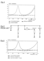
- FIG. 2 shows a comparison of the SPL between a conventional driver and a dual-coil driver used in the same closed box system, showing that the dual-coil system is 2 dB louder than the conventional system in this example.
- Figure 3 shows the same comparison from an impedance point of view, the LC circuit causes the large peak around the fundamental resonance of the loudspeaker to disappear and the resulting impedance is equivalent to a pure resistance whose value is not below the recommended minimum impedance for a loudspeaker, typically 3.2 ohms. It is important to have a low impedance target, and driver resistance is minimised so as to enable voltage sensitivity (how loud the speaker can be without acoustic distortion) to be maximised.
- FIG. 6 is a plot of the loudspeaker impedance with and without a Zobel network, and shows that, although the Zobel network cancels the inductance at high frequencies, the minimum impedance of this particular dual-coil system drops to 2.2 ohms at 140 Hz, which is even lower than if no Zobel network is used.
- Z z so-called "Zobel network”
- Z z typically a capacitor in series with a resistor - in parallel with the primary voice coil and in parallel with the secondary voice coil, the resonant circuit and the inductance compensation filter
- the present invention is predicated on the realisation that a relatively simple inductance compensation filter can be used with a dual-coil loudspeaker driver and significantly improve its overall performance compared to conventional systems.
- the present invention therefore provides electrical circuitry adapted to drive a dual-coil loudspeaker having a primary voice coil and a second voice coil connected in parallel with the primary voice coil, the second voice coil being in series with a resonant circuit of impedance Z mf , further comprising an inductance compensation filter of impedance Z if in parallel with the resonant circuit (which may be an LC or an RLC circuit).
- the addition of the inductance compensation filter not only cancels the effect of the inductance (the monotonic rise at high frequencies), but also and more importantly removes the dip in the impedance as shown in Figure 6 ; this effect is shown in Figure 8 and described further below.
- R e1 is the resistance of the primary voice coil
- j is the imaginary operator
- ⁇ is the circular frequency
- L e1 ( ⁇ ) is the complex frequency-dependent inductance of the primary voice coil
- L e 1 ⁇ Z eb ⁇ ⁇ Z eb 0 / j ⁇
- Z eb ( ⁇ ) is the frequency dependent blocked impedance
- Z eb (0) is the DC blocked impedance.
- the inductance compensation filter may comprise a capacitor C1, or a capacitor C1 in series with a resistor R1.
- the simplest circuit uses a capacitor alone, but sometimes a resistor in series with the capacitor is used for fine tuning.
- the inductance in the dual-coil driver is frequency-dependent, and in such cases a semi-inductance model can be used.
- the semi-inductance model may be effected by the inductance compensation filter comprising a capacitor C1 in series with a resistor R1 and, in series, a further capacitor C2 in parallel with a resistor R2. Additionally, the inductance compensation filter may further comprise, in series, a further capacitor C3 in parallel with a further resistance R3.
- the circuitry may further comprise a voltage divider R4 - R5 located in series between the parallel-connected resonant circuit and the inductance compensation filter, and the second voice coil.
- the dual-coil arrangement gives an opportunity unachievable with a conventional single coil driver: the control of the Q-factor without changing the input impedance. This allows control of the pressure response at low frequency, giving more flexibility for the user in locating the loudspeaker in a room for example.
- the electrical circuitry may additionally comprise a Zobel network in parallel with the parallel drivers for the primary and the secondary voice coils, compensation circuit and voltage divider. This is used to compensate for any residual effects of the inductance.
- the primary and second voice coils may be coaxial and share the same magnetic gap, as in US3838216 .
- the primary and second voice coils may be coaxial and operate in separate magnetic gaps (where the second driver is behind the primary driver and operates rearwardly so as to use the same motor system).
- the primary and secondary voice coils may be separate, in an isobaric arrangement.
- FIGS 1 to 6 relate to the prior art and are described in the introduction above.
- Figure 7 shows the basic circuit in accordance with the invention to cancel the effect of the voice coil inductance, It consists of an inductance compensation filter Z if - typically but not exclusively, a capacitor in series with an optional resistor - in parallel to the original circuit Z mf driving the second voice coil, voice coil 2, which is driven in parallel with the primary voice coil, voice coil 1.
- Figure 8 shows that when the circuit of Figure 7 is used not only is the effect of the inductance annihilated (the monotonic rise at high frequencies), but more importantly no dip is present in the impedance.
- Figure 9 shows the circuit of Figure 7 adapted to cancel the effect of the inductance with a Zobel network Z z adapted to cancel the effect of any residual inductance.
- the Z if circuit compensates the inductance of the loudspeaker.
- the Z mf circuit compensates the mechanical load seen by the loudspeaker; therefore, its topology depends on the type of environment in which the loudspeaker is placed. If used in free air, in a baffle or a closed box, the RLC (resistor R inductor L capacitor C) circuit shown in Figure 10 is sufficient to flatten the impedance. If the loudspeaker is used in a ported enclosure, the Z mf circuit is instead as shown in Figure 11 , and comprises: a first branch R1-L1-C1 that compensates the loudspeaker; a second branch R2-C2 that compensates the box, and a third branch R3-L3 that compensates the vent.
- the Z if circuit compensates the inductance of the loudspeaker and is shown in Figure 12 .
- the simplest circuit uses a single capacitor C1 but sometimes a resistor R1 in series is needed for fine tuning.
- the inductance is frequency-dependent and it is required to use a so-called semi-inductance model, involving several branches.
- Figure 13 and Figure 14 show respectively compensation circuits LR2 and LR3 which are the most common semi-inductance models.
- the dual-coil arrangement gives an opportunity unachievable with a conventional single coil driver: the control of the Q-factor without changing the input impedance.
- the principle is to insert a voltage divider R4 - R5 between the electrical circuit of impedance Z ef and the secondary voice coil, as shown in Figure 15 .
- the voltage divider may use two inductors L1 and L2 respectively in series with the resistors R4 and R5, as shown in Figure 16 .
- the effect, depicted in Figure 17 is to allow control of the pressure response at low frequency, giving more flexibility for the user in the loudspeaker placement in a room for example.
- the motor system described above uses a single magnetic gap shared by the two voice coils, as shown in Figure 18a .
- An alternative is, while still using the same motor system, to use one gap per voice coil, as in Figure 18b , where the diaphragm of the second voice coil is behind the diaphragm of the primary voice coil and radiates rearwardly.
- two motors could drive the same diaphragm as in Figure 19(a) , or a small acoustic chamber could be placed between two drivers as in Figure 19(b) ; the latter arrangement is an isobaric arrangement.
Landscapes
- Physics & Mathematics (AREA)
- Engineering & Computer Science (AREA)
- Acoustics & Sound (AREA)
- Signal Processing (AREA)
- Electromagnetism (AREA)
- Circuit For Audible Band Transducer (AREA)
- Audible-Bandwidth Dynamoelectric Transducers Other Than Pickups (AREA)
Claims (11)
- Elektrische Schaltungsanordnung, ausgelegt zum Ansteuern eines Doppelspulenlautsprechers mit einer primären Schwingspule und einer zweiten Schwingspule, die mit der primären Schwingspule parallel geschaltet ist, wobei die zweite Schwingspule mit einem Schwingkreis der Impedanz Zmf in Reihe geschaltet ist, dadurch gekennzeichnet, dass die elektrische Schaltungsanordnung ein Induktivitätskompensationsfilter der Impedanz Zif in Parallelschaltung mit dem Schwingkreis umfasst, wobei das Induktivitätskompensationsfilter dazu ausgelegt ist, die Induktivitäten der primären und sekundären Schwingspule zu kompensieren.
- Elektrische Schaltungsanordnung nach Anspruch 1, wobei die Impedanz des Induktivitätskompensationsfilters gegeben ist durch
 wobei R e1 der Widerstand der primären Schwingspule ist, j der imaginäre Operator ist, ω die Kreisfrequenz ist und L e1(ω) die frequenzabhängige Induktivität der primären Schwingspule ist, und wobei
 wobei Zeb (ω) die frequenzabhängige blockierte Impedanz ist und Zeb (0) die blockierte DC-Impedanz ist.
 - Elektrische Schaltungsanordnung nach Anspruch 1 oder Anspruch 2, wobei die Impedanz des Schwingkreises gegeben ist durch

- Elektrische Schaltungsanordnung nach Anspruch 1, 2 oder 3, wobei das Induktivitätskompensationsfilter einen Kondensator C1 oder einen Kondensator C1 in Reihenschaltung mit einem Widerstand R1 umfasst.
- Elektrische Schaltungsanordnung nach Anspruch 4, wobei das Induktivitätskompensationsfilter einen Kondensator C1 in Reihenschaltung mit einem Widerstand R1 und, in Reihenschaltung, einen weiteren Kondensator C2 in Parallelschaltung mit einem Widerstand R2 umfasst.
- Elektrische Schaltungsanordnung nach Anspruch 5, wobei das Induktivitätskompensationsfilter ferner einen weiteren Kondensator C3 in Parallelschaltung mit einem weiteren Widerstand R3 umfasst.
- Elektrische Schaltungsanordnung nach einem der vorhergehenden Ansprüche, ferner umfassend einen Spannungsteiler R4-R5, der sich in Reihenschaltung zwischen:(i) dem parallel geschalteten Schwingkreis und dem Induktivitätskompensationsfilter und(ii) der zweiten Schwingspulebefindet.
- Elektrische Schaltungsanordnung nach einem der vorhergehenden Ansprüche, ferner umfassend ein Zobel-Netzwerk in Parallelschaltung mit der primären Schwingspule und in Parallelschaltung mit der sekundären Schwingspule, dem Schwingkreis und dem Induktivitätskompensationsfilter.
- Elektrische Schaltungsanordnung nach einem der vorhergehenden Ansprüche, wobei die primäre und die zweite Schwingspule koaxial sind und sich denselben Magnetspalt teilen.
- Elektrische Schaltungsanordnung nach einem der Ansprüche 1 bis 8, wobei die primäre und die zweite Schwingspule koaxial sind und in separaten Magnetspalten arbeiten.
- Elektrische Schaltungsanordnung nach Anspruch 9, wobei die primäre und die zweite Schwingspule durch eine akustische Kammer getrennt sind.
Applications Claiming Priority (1)
| Application Number | Priority Date | Filing Date | Title |
|---|---|---|---|
| GB2117411.5A GB2613388A (en) | 2021-12-02 | 2021-12-02 | Loudspeaker circuitry |
Publications (2)
| Publication Number | Publication Date |
|---|---|
| EP4192034A1 EP4192034A1 (de) | 2023-06-07 |
| EP4192034B1 true EP4192034B1 (de) | 2024-09-25 |
Family
ID=80081033
Family Applications (1)
| Application Number | Title | Priority Date | Filing Date |
|---|---|---|---|
| EP22207874.3A Active EP4192034B1 (de) | 2021-12-02 | 2022-11-16 | Doppelschwingspulen-lautsprecherschaltung |
Country Status (4)
| Country | Link |
|---|---|
| US (1) | US12323777B2 (de) |
| EP (1) | EP4192034B1 (de) |
| CN (1) | CN116233689A (de) |
| GB (1) | GB2613388A (de) |
Family Cites Families (8)
| Publication number | Priority date | Publication date | Assignee | Title |
|---|---|---|---|---|
| US3838216A (en) * | 1972-02-23 | 1974-09-24 | W Watkins | Device to effectively eliminate the motion induced back emf in a loudspeaker system in the region of fundamental acoustic resonance |
| JPS5936689U (ja) * | 1982-08-31 | 1984-03-07 | パイオニア株式会社 | スピ−カ装置 |
| JPS61161895A (ja) * | 1985-01-11 | 1986-07-22 | Matsushita Electric Ind Co Ltd | スピ−カシステム |
| JPH11146479A (ja) * | 1997-11-11 | 1999-05-28 | Mitsubishi Electric Corp | スピーカーシステム |
| JPH11146486A (ja) * | 1997-11-11 | 1999-05-28 | Mitsubishi Electric Corp | スピーカーシステム |
| EP1686834A1 (de) * | 2005-01-28 | 2006-08-02 | Sonion Horsens A/S | Miniature-Mehrfachlautsprechermodul |
| US20100195863A1 (en) * | 2006-11-17 | 2010-08-05 | Pioneer Corporation | Speaker |
| IT201800005087A1 (it) * | 2018-05-04 | 2019-11-04 | Padiglione elettroacustico per cuffie del tipo aperto |
-
2021
- 2021-12-02 GB GB2117411.5A patent/GB2613388A/en active Pending
-
2022
- 2022-11-07 US US17/982,235 patent/US12323777B2/en active Active
- 2022-11-16 EP EP22207874.3A patent/EP4192034B1/de active Active
- 2022-12-02 CN CN202211535985.9A patent/CN116233689A/zh active Pending
Also Published As
| Publication number | Publication date |
|---|---|
| GB202117411D0 (en) | 2022-01-19 |
| US20230179916A1 (en) | 2023-06-08 |
| US12323777B2 (en) | 2025-06-03 |
| EP4192034A1 (de) | 2023-06-07 |
| GB2613388A (en) | 2023-06-07 |
| CN116233689A (zh) | 2023-06-06 |
Similar Documents
| Publication | Publication Date | Title |
|---|---|---|
| EP2215856B1 (de) | Elektrtostatisches lautsprecher system | |
| US4769848A (en) | Electroacoustic network | |
| JP4243021B2 (ja) | 電気音響スピーカ用コンデンサの無いクロスオーバ・ネットワーク | |
| EP1135966A2 (de) | Akustische biegewellen-vorrichtungen | |
| EP3185241B1 (de) | Extern gekoppeltes lautsprechersystem | |
| JP3223793B2 (ja) | スピーカシステム | |
| KR20140032907A (ko) | 스피커 코일을 통해 무선 주파수 신호를 전송하기 위한 시스템 및 방법 | |
| JPH0752994B2 (ja) | スピーカー駆動装置 | |
| CN110018808A (zh) | 一种音质调整方法及装置 | |
| WO2005055460A1 (en) | Resonance frequency shift canceling in wireless hearing aids | |
| WO2008109327A2 (en) | Audio system with synthesized positive impedance | |
| EP2629289A1 (de) | System zur aktiven Geräuschkontrolle mit Rückkopplung und einem langen zweiten PFad | |
| EP4192034A1 (de) | Doppelschwingspulen-lautsprecherschaltung | |
| US20120039484A1 (en) | Speaker with frequency directed dual drivers | |
| US4483015A (en) | Compensation network for loudspeakers | |
| US20170127171A1 (en) | Noise reduction system | |
| HK40095773A (zh) | 扬声器电路 | |
| GB2473921A (en) | Compensation of rising frequency response in passive current-driven loudspeakers | |
| US7085389B1 (en) | Infinite slope loudspeaker crossover filter | |
| US5121088A (en) | Frequency response equalizer | |
| US6259799B1 (en) | Speaker system | |
| US6707919B2 (en) | Driver control circuit | |
| EP2257082A1 (de) | Hintergrundgeräusch-Schätzung in einem Lautsprecher-Raum-Mikrophon-System | |
| AU2004204987B2 (en) | Loudspeaker system with extended output and field cancellation | |
| EP1584215A1 (de) | Lautsprechersystem mit verbesserter ausgabe und feldaufhebung |
Legal Events
| Date | Code | Title | Description |
|---|---|---|---|
| PUAI | Public reference made under article 153(3) epc to a published international application that has entered the european phase |
Free format text: ORIGINAL CODE: 0009012 |
|
| STAA | Information on the status of an ep patent application or granted ep patent |
Free format text: STATUS: THE APPLICATION HAS BEEN PUBLISHED |
|
| AK | Designated contracting states |
Kind code of ref document: A1 Designated state(s): AL AT BE BG CH CY CZ DE DK EE ES FI FR GB GR HR HU IE IS IT LI LT LU LV MC ME MK MT NL NO PL PT RO RS SE SI SK SM TR |
|
| STAA | Information on the status of an ep patent application or granted ep patent |
Free format text: STATUS: REQUEST FOR EXAMINATION WAS MADE |
|
| 17P | Request for examination filed |
Effective date: 20231128 |
|
| RBV | Designated contracting states (corrected) |
Designated state(s): AL AT BE BG CH CY CZ DE DK EE ES FI FR GB GR HR HU IE IS IT LI LT LU LV MC ME MK MT NL NO PL PT RO RS SE SI SK SM TR |
|
| GRAP | Despatch of communication of intention to grant a patent |
Free format text: ORIGINAL CODE: EPIDOSNIGR1 |
|
| STAA | Information on the status of an ep patent application or granted ep patent |
Free format text: STATUS: GRANT OF PATENT IS INTENDED |
|
| RIC1 | Information provided on ipc code assigned before grant |
Ipc: H04R 1/22 20060101ALN20240405BHEP Ipc: H04R 3/08 20060101ALI20240405BHEP Ipc: H04R 9/06 20060101AFI20240405BHEP |
|
| INTG | Intention to grant announced |
Effective date: 20240424 |
|
| GRAS | Grant fee paid |
Free format text: ORIGINAL CODE: EPIDOSNIGR3 |
|
| GRAA | (expected) grant |
Free format text: ORIGINAL CODE: 0009210 |
|
| STAA | Information on the status of an ep patent application or granted ep patent |
Free format text: STATUS: THE PATENT HAS BEEN GRANTED |
|
| AK | Designated contracting states |
Kind code of ref document: B1 Designated state(s): AL AT BE BG CH CY CZ DE DK EE ES FI FR GB GR HR HU IE IS IT LI LT LU LV MC ME MK MT NL NO PL PT RO RS SE SI SK SM TR |
|
| RAP3 | Party data changed (applicant data changed or rights of an application transferred) |
Owner name: GP ACOUSTICS INTERNATIONAL LIMITED |
|
| REG | Reference to a national code |
Ref country code: GB Ref legal event code: FG4D |
|
| REG | Reference to a national code |
Ref country code: CH Ref legal event code: EP |
|
| REG | Reference to a national code |
Ref country code: DE Ref legal event code: R096 Ref document number: 602022006367 Country of ref document: DE |
|
| REG | Reference to a national code |
Ref country code: IE Ref legal event code: FG4D |
|
| REG | Reference to a national code |
Ref country code: LT Ref legal event code: MG9D |
|
| PG25 | Lapsed in a contracting state [announced via postgrant information from national office to epo] |
Ref country code: NO Free format text: LAPSE BECAUSE OF FAILURE TO SUBMIT A TRANSLATION OF THE DESCRIPTION OR TO PAY THE FEE WITHIN THE PRESCRIBED TIME-LIMIT Effective date: 20241225 |
|
| PG25 | Lapsed in a contracting state [announced via postgrant information from national office to epo] |
Ref country code: GR Free format text: LAPSE BECAUSE OF FAILURE TO SUBMIT A TRANSLATION OF THE DESCRIPTION OR TO PAY THE FEE WITHIN THE PRESCRIBED TIME-LIMIT Effective date: 20241226 Ref country code: FI Free format text: LAPSE BECAUSE OF FAILURE TO SUBMIT A TRANSLATION OF THE DESCRIPTION OR TO PAY THE FEE WITHIN THE PRESCRIBED TIME-LIMIT Effective date: 20240925 |
|
| PG25 | Lapsed in a contracting state [announced via postgrant information from national office to epo] |
Ref country code: BG Free format text: LAPSE BECAUSE OF FAILURE TO SUBMIT A TRANSLATION OF THE DESCRIPTION OR TO PAY THE FEE WITHIN THE PRESCRIBED TIME-LIMIT Effective date: 20240925 |
|
| PG25 | Lapsed in a contracting state [announced via postgrant information from national office to epo] |
Ref country code: LV Free format text: LAPSE BECAUSE OF FAILURE TO SUBMIT A TRANSLATION OF THE DESCRIPTION OR TO PAY THE FEE WITHIN THE PRESCRIBED TIME-LIMIT Effective date: 20240925 |
|
| PG25 | Lapsed in a contracting state [announced via postgrant information from national office to epo] |
Ref country code: RS Free format text: LAPSE BECAUSE OF FAILURE TO SUBMIT A TRANSLATION OF THE DESCRIPTION OR TO PAY THE FEE WITHIN THE PRESCRIBED TIME-LIMIT Effective date: 20241225 |
|
| REG | Reference to a national code |
Ref country code: NL Ref legal event code: MP Effective date: 20240925 |
|
| PG25 | Lapsed in a contracting state [announced via postgrant information from national office to epo] |
Ref country code: RS Free format text: LAPSE BECAUSE OF FAILURE TO SUBMIT A TRANSLATION OF THE DESCRIPTION OR TO PAY THE FEE WITHIN THE PRESCRIBED TIME-LIMIT Effective date: 20241225 Ref country code: NO Free format text: LAPSE BECAUSE OF FAILURE TO SUBMIT A TRANSLATION OF THE DESCRIPTION OR TO PAY THE FEE WITHIN THE PRESCRIBED TIME-LIMIT Effective date: 20241225 Ref country code: LV Free format text: LAPSE BECAUSE OF FAILURE TO SUBMIT A TRANSLATION OF THE DESCRIPTION OR TO PAY THE FEE WITHIN THE PRESCRIBED TIME-LIMIT Effective date: 20240925 Ref country code: GR Free format text: LAPSE BECAUSE OF FAILURE TO SUBMIT A TRANSLATION OF THE DESCRIPTION OR TO PAY THE FEE WITHIN THE PRESCRIBED TIME-LIMIT Effective date: 20241226 Ref country code: FI Free format text: LAPSE BECAUSE OF FAILURE TO SUBMIT A TRANSLATION OF THE DESCRIPTION OR TO PAY THE FEE WITHIN THE PRESCRIBED TIME-LIMIT Effective date: 20240925 Ref country code: BG Free format text: LAPSE BECAUSE OF FAILURE TO SUBMIT A TRANSLATION OF THE DESCRIPTION OR TO PAY THE FEE WITHIN THE PRESCRIBED TIME-LIMIT Effective date: 20240925 |
|
| REG | Reference to a national code |
Ref country code: AT Ref legal event code: MK05 Ref document number: 1727670 Country of ref document: AT Kind code of ref document: T Effective date: 20240925 |
|
| PG25 | Lapsed in a contracting state [announced via postgrant information from national office to epo] |
Ref country code: NL Free format text: LAPSE BECAUSE OF FAILURE TO SUBMIT A TRANSLATION OF THE DESCRIPTION OR TO PAY THE FEE WITHIN THE PRESCRIBED TIME-LIMIT Effective date: 20240925 |
|
| PG25 | Lapsed in a contracting state [announced via postgrant information from national office to epo] |
Ref country code: IS Free format text: LAPSE BECAUSE OF FAILURE TO SUBMIT A TRANSLATION OF THE DESCRIPTION OR TO PAY THE FEE WITHIN THE PRESCRIBED TIME-LIMIT Effective date: 20250125 Ref country code: PT Free format text: LAPSE BECAUSE OF FAILURE TO SUBMIT A TRANSLATION OF THE DESCRIPTION OR TO PAY THE FEE WITHIN THE PRESCRIBED TIME-LIMIT Effective date: 20250127 |
|
| PG25 | Lapsed in a contracting state [announced via postgrant information from national office to epo] |
Ref country code: SM Free format text: LAPSE BECAUSE OF FAILURE TO SUBMIT A TRANSLATION OF THE DESCRIPTION OR TO PAY THE FEE WITHIN THE PRESCRIBED TIME-LIMIT Effective date: 20240925 Ref country code: RO Free format text: LAPSE BECAUSE OF FAILURE TO SUBMIT A TRANSLATION OF THE DESCRIPTION OR TO PAY THE FEE WITHIN THE PRESCRIBED TIME-LIMIT Effective date: 20240925 |
|
| PG25 | Lapsed in a contracting state [announced via postgrant information from national office to epo] |
Ref country code: ES Free format text: LAPSE BECAUSE OF FAILURE TO SUBMIT A TRANSLATION OF THE DESCRIPTION OR TO PAY THE FEE WITHIN THE PRESCRIBED TIME-LIMIT Effective date: 20240925 |
|
| PG25 | Lapsed in a contracting state [announced via postgrant information from national office to epo] |
Ref country code: AT Free format text: LAPSE BECAUSE OF FAILURE TO SUBMIT A TRANSLATION OF THE DESCRIPTION OR TO PAY THE FEE WITHIN THE PRESCRIBED TIME-LIMIT Effective date: 20240925 Ref country code: EE Free format text: LAPSE BECAUSE OF FAILURE TO SUBMIT A TRANSLATION OF THE DESCRIPTION OR TO PAY THE FEE WITHIN THE PRESCRIBED TIME-LIMIT Effective date: 20240925 |
|
| PG25 | Lapsed in a contracting state [announced via postgrant information from national office to epo] |
Ref country code: PL Free format text: LAPSE BECAUSE OF FAILURE TO SUBMIT A TRANSLATION OF THE DESCRIPTION OR TO PAY THE FEE WITHIN THE PRESCRIBED TIME-LIMIT Effective date: 20240925 Ref country code: CZ Free format text: LAPSE BECAUSE OF FAILURE TO SUBMIT A TRANSLATION OF THE DESCRIPTION OR TO PAY THE FEE WITHIN THE PRESCRIBED TIME-LIMIT Effective date: 20240925 |
|
| PG25 | Lapsed in a contracting state [announced via postgrant information from national office to epo] |
Ref country code: IT Free format text: LAPSE BECAUSE OF FAILURE TO SUBMIT A TRANSLATION OF THE DESCRIPTION OR TO PAY THE FEE WITHIN THE PRESCRIBED TIME-LIMIT Effective date: 20240925 Ref country code: SK Free format text: LAPSE BECAUSE OF FAILURE TO SUBMIT A TRANSLATION OF THE DESCRIPTION OR TO PAY THE FEE WITHIN THE PRESCRIBED TIME-LIMIT Effective date: 20240925 |
|
| REG | Reference to a national code |
Ref country code: DE Ref legal event code: R097 Ref document number: 602022006367 Country of ref document: DE |
|
| PG25 | Lapsed in a contracting state [announced via postgrant information from national office to epo] |
Ref country code: MC Free format text: LAPSE BECAUSE OF FAILURE TO SUBMIT A TRANSLATION OF THE DESCRIPTION OR TO PAY THE FEE WITHIN THE PRESCRIBED TIME-LIMIT Effective date: 20240925 |
|
| PG25 | Lapsed in a contracting state [announced via postgrant information from national office to epo] |
Ref country code: DK Free format text: LAPSE BECAUSE OF FAILURE TO SUBMIT A TRANSLATION OF THE DESCRIPTION OR TO PAY THE FEE WITHIN THE PRESCRIBED TIME-LIMIT Effective date: 20240925 |
|
| PG25 | Lapsed in a contracting state [announced via postgrant information from national office to epo] |
Ref country code: LU Free format text: LAPSE BECAUSE OF NON-PAYMENT OF DUE FEES Effective date: 20241116 |
|
| PLBE | No opposition filed within time limit |
Free format text: ORIGINAL CODE: 0009261 |
|
| STAA | Information on the status of an ep patent application or granted ep patent |
Free format text: STATUS: NO OPPOSITION FILED WITHIN TIME LIMIT |
|
| REG | Reference to a national code |
Ref country code: BE Ref legal event code: MM Effective date: 20241130 |
|
| 26N | No opposition filed |
Effective date: 20250626 |
|
| PG25 | Lapsed in a contracting state [announced via postgrant information from national office to epo] |
Ref country code: SE Free format text: LAPSE BECAUSE OF FAILURE TO SUBMIT A TRANSLATION OF THE DESCRIPTION OR TO PAY THE FEE WITHIN THE PRESCRIBED TIME-LIMIT Effective date: 20240925 |
|
| PG25 | Lapsed in a contracting state [announced via postgrant information from national office to epo] |
Ref country code: BE Free format text: LAPSE BECAUSE OF NON-PAYMENT OF DUE FEES Effective date: 20241130 |
|
| PGFP | Annual fee paid to national office [announced via postgrant information from national office to epo] |
Ref country code: FR Payment date: 20250916 Year of fee payment: 4 |
|
| PG25 | Lapsed in a contracting state [announced via postgrant information from national office to epo] |
Ref country code: IE Free format text: LAPSE BECAUSE OF NON-PAYMENT OF DUE FEES Effective date: 20241116 |
|
| PGFP | Annual fee paid to national office [announced via postgrant information from national office to epo] |
Ref country code: DE Payment date: 20250916 Year of fee payment: 4 |
|
| PG25 | Lapsed in a contracting state [announced via postgrant information from national office to epo] |
Ref country code: HR Free format text: LAPSE BECAUSE OF FAILURE TO SUBMIT A TRANSLATION OF THE DESCRIPTION OR TO PAY THE FEE WITHIN THE PRESCRIBED TIME-LIMIT Effective date: 20240925 |
|
| PG25 | Lapsed in a contracting state [announced via postgrant information from national office to epo] |
Ref country code: HU Free format text: LAPSE BECAUSE OF FAILURE TO SUBMIT A TRANSLATION OF THE DESCRIPTION OR TO PAY THE FEE WITHIN THE PRESCRIBED TIME-LIMIT; INVALID AB INITIO Effective date: 20221116 |
|
| PG25 | Lapsed in a contracting state [announced via postgrant information from national office to epo] |
Ref country code: CY Free format text: LAPSE BECAUSE OF FAILURE TO SUBMIT A TRANSLATION OF THE DESCRIPTION OR TO PAY THE FEE WITHIN THE PRESCRIBED TIME-LIMIT; INVALID AB INITIO Effective date: 20221116 |